

Page 1
Installation Instructions and User Guide
®
F
M
APPROVED
R
LISTED
for the Frostex Pipe Freeze Protection System
Using the 9800 FlexFit Plug Kit
Directives d’installation et Guide de l’Utilisateur
du Système Frostex de Protection Anti-gel des
Tuyaux Utilisé avec le Kit Frostex 9800 FlexFit
Keep pipes from freezing
Protection anti-gel des tuyaux
60J9 Residential
and Mobile Home
Pipe Heating Cable
Page 2
Contents
Five Important Safety Warnings 1
General Instructions 2
Installation Instructions 2
Periodic Inspections 8
Troubleshooting 8
ENGLISHFRANÇAIS
Limited Warranty 9
Table des matières
Cinq avertissements de sécurité importants 1
Directives générales 10
Directives d’installation 10
Inspections périodiques 16
Dépannage 16
Garantie limitée 17
9800 FlexFit plug
Ground-fault unit
Reset button
Test button
K
G
a
rd
T
ES
er
T
au s
ec
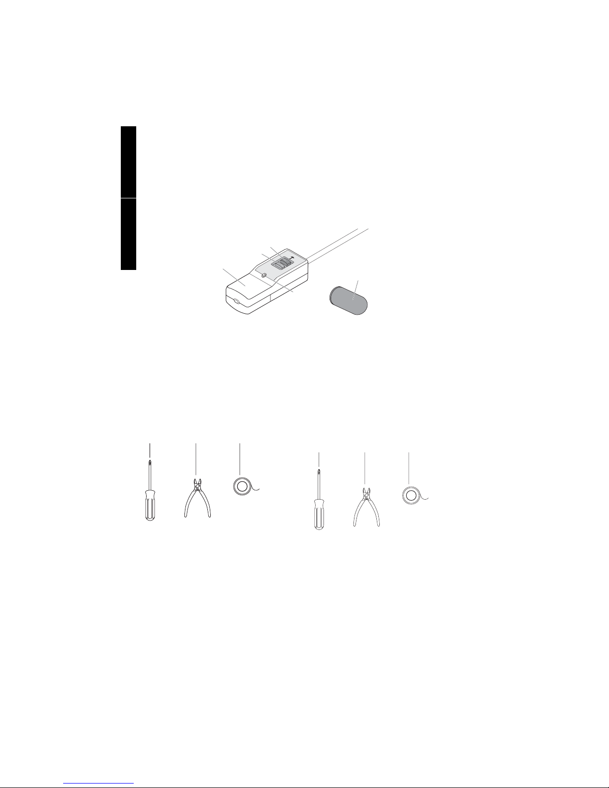
Before You Begin
Make sure your 9800 FlexFit Plug Kit is complete. It should contain:
1 9800 FlexFit plug
1 Push-on end seal
2 Orange warning labels in English
2 Orange warning labels in French
1 White tape strip
1 Installation instruction
Make sure you have sufficient braided Frostex heating
cable for the job. Do not use earlier versions of Frostex
heating cable that have no braid. Also make sure you
have the following items:
#2 Phillips
screwdriver
Wire cutters
1/2"–1"
(13 mm–25 mm)
tape*
ee
p
dry
Gel-filled end seal
Indicator
light
Avant de débuter
Assurez-vous que votre kit 9800 FlexFit contient tout ce qui
suit:
1 Fiche 9800 FlexFit
1 Obturateur à pousser
2 Étiquettes oranges d’avertissement en anglais
2 Étiquettes oranges d’avertissement en français
1 Bande de ruban blanc
1 Manuel des directives d’installation
Assurez-vous d’avoir suffisamment de câble chauffant tressé
Frostex pour effectuer le travail. N’employez pas les versions
antérieures des câbles chauffants Frostex sans tresses.
Ayez également les articles suivants en main:
Tournevis
Phillips°2
Un
coupe-câble
Du ruban *
de 13 mm-25 mm
(1/2-1po)
*Frostex 9610 application tape is recommended.
Two 10" (25 cm) plastic cable ties (not included) may be used
to secure ground-fault unit to pipe insulation.
If you have any questions after reading this guide, call this
toll-free Tyco Thermal Controls number: (800) 545-6258.
Save this installation instruction and user guide. It contains important safety warnings and maintenance information.
*Le ruban de fixation Frostex 9610 est recommandé.
Deux colliers de serrage en plastique de 25 cm (10 po) (non
inclus) peuvent être utilisés pour fixer le disjoncteur différentiel
à l’isolant de tuyaux.
Si vous avez des questions après la lecture du présent guide,
contactez le numéro sans frais de Tyco Thermal Controls au :
(800) 545-6258.
Conservez ces directives d’installation ainsi que le
guide de l’utilisateur. Ils contiennent d’importants
avertissements de sécurité et une notice d’entretien.
Page 3

Five Important Safety Warnings
Follow all five of these instructions to prevent fire
or shock:
1. Use the correct heating cable.
• Use only braided versions of Frostex heating cable.
• Earlier versions of Frostex heating cable with no braid
are not compatible.
2. Use the right end seal and plug.
• Seal the heating cable only with the end seal provided;
do not use electrical tape.
• Use the 9800 FlexFit plug contained in this kit. It has
special safety features.
• Use the 9800 FlexFit Plug Kit only with Frostex heating
cable.
3. Do not twist wires together or allow them to
touch each other.
• Do not strip the heating cable. If wires touch, the nonreplaceable fuse will blow and the system will not work.
4. Keep the entire Frostex system dry. This includes
the insulation.
If the system gets wet, pipes may freeze.
• Use the system only on insulated residential pipes
carrying water.
• Do not use the system on buried pipes.
• Do not use the system to de-ice roofs or gutters.
• Do not install any part of the heating system where it
would be under water.
• Do not use where water is likely to enter the plug.
5. The blue plastic heating cable and the metal
braid must not be cut or damaged.
• Before you begin, inspect the pipe. File and remove any
sharp edges. Make sure the heating cable crosses only
smooth, nonabrasive surfaces.
• Where the system might be damaged by animals or
objects, protect the complete system with a solid cover,
such as sheet metal or additional pipe insulation.
• Do not use any wire or clamps to attach the heating
cable to the pipe. Instead, use the Frostex 9610 application tape, or equivalent 1/2"–1" (13 mm–25 mm) tape,
or plastic cable ties.
• Inspect the heating cable periodically for damage. If you
discover broken braid or other damage, immediately disconnect the system and replace the heating cable. Do not
splice or repair a damaged heating cable. You must replace
any damaged insulation or waterproof covering.
6. Do not install Frostex heating cable close to
flammable materials, liquids, or fumes.
Use only 1/2" (13 mm) or thicker fire-retardant and waterproof
pipe insulation, in accordance with Table 1 or 2.
Cinq avertissements de sécurité
importants
Veuillez suivre les cinq directives suivantes afin de
prévenir les risques d’incendie ou de choc électrique:
1. Utilisez le câble chauffant adéquat.
• Employez uniquement les versions tressées des câbles
chauffants Frostex.
• Les versions antérieures des câbles chauffants Frostex
sans tresses ne sont pas compatibles.
2. Utilisez la fiche et l’obturateur appropriés.
• Étanchéifiez le câble chauffant à l’aide de l’obturateur
fourni seulement; n’utilisez pas de ruban isolant.
• Utilisez la fiche 9800 FlexFit incluse dans ce kit; elle est
dotée de caractéristiques de sécurité spéciales.
• Utilisez le kit 9800 FlexFit uniquement avec le câble
chauffant Frostex.
3. Ne torsadez pas les fils ensemble ni ne leur permettez de se toucher.
• Ne dénudez pas le cable chauffant. Si des fils se
touchent, le fusible non remplaçable sautera et le système ne fonctionnera plus.
4. Gardez le système Frostex au sec en entier, y
compris l’isolant.
Les tuyaux risquent de geler si de l’humidité pénètre dans
le système.
• Utilisez le système uniquement sur des tuyaux résidentiels et isolés, transportant de l’eau.
• N’utilisez pas le système sur des tuyaux souterrains.
• N’utilisez pas le système pour dégivrer des toits ou des
gouttières.
• N’installez aucun élément du système de chauffage en
zones immergées.
• N’utilisez le système pas dans des zones où de l’eau risquerait de pénétrer dans la fiche.
5. Le câble chauffant en plastique bleu et la tresse
métallique ne doivent pas être coupés ou endommagés.
• Avant de débuter l’installation, inspectez le tuyau, limez et
enlevez les rebords acérés. Le câble ne doit croiser que des
surfaces lisses et non-abrasives.
• Si le système risque d’être endommagé par des animaux ou
des objets, protégez le en le recouvrant en entier d’un
revêtement solide comme une tôle, ou de l’isolant à tuyau
supplémentaire.
• N’utilisez pas de fils ou de griffes pour fixer le câble chauffant sur le tuyau. Utilisez plutôt le ruban de fixation Frostex
9610, ou un autre ruban équivalent de 1/2 po-1 po (13
mm-25 mm), ou des colliers de serrage en plastique.
• Inspectez le câble chauffant périodiquement. Si vous
décelez la présence de tresses brisées ou autres éléments
endommagés, débranchez le système immédiatement et
remplacez le câble chauffant. Vous ne devez pas tenter de
coller ou de réparer un câble chauffant endommagé. Vous
devez remplacer les isolants et recouvrements imperméables endommagés.
6. N’installez pas le câble chauffant Frostex à proximité de matières, liquides ou vapeurs inflammables.
N’utilisez que de l’isolant à tuyau ayant 1/2 po (13 mm) d’épaisseur ou plus, ignifuge et résistant à l’eau, conformément au Tableau 1 ou 2.
1
ENGLISH FRANÇAIS
Page 4
General Instructions
• Observe the safety warnings on page 1. Follow the
installation steps (pages 2–7) in the exact order given.
• To ensure the plug is properly connected, do not assemble
at temperatures below 0°F (–18°C).
• The Frostex system can be left plugged in all year, but you
ENGLISH
will save energy by unplugging the system when there is
no risk of freezing.
• Use a properly grounded, 3-prong, 120-volt outlet. If you
are not sure if your outlet is properly grounded, call a
professional service person.
• In manufactured housing installations, use the electrical
receptacle on the underside of the home. Do not use an
extension cord or there may be danger of fire or shock.
Using an extension cord is not in compliance with national
electrical codes.
• Frostex heating cable may be used on metal or plastic pipes
and tubing. Do not install on garden hoses or in applications
with tubing that is flexed frequently.
• Exposure to temperatures above 150°F (65°C) will shorten
the life of your Frostex heating cable. Before installing the
heating cable on hot water pipes, set the water heater thermostat below 150°F (65°C), low to medium on most thermostats.
• Remove any old heating tapes and insulation before you
install the Frostex heating cable.
• Do not use more than 50 feet (15 meters) of Frostex heating cable with each 9800 FlexFit plug. Longer lengths will
blow the nonreplaceable fuse in the plug.
• The homeowner will need to keep these instructions for
future reference. It contains important safety warnings and
maintenance information.
• If you have any difficulty installing the system, please contact
Tyco Thermal Controls for information at (800) 545-6258, or
call a professional service person for help.
• Remove the clear label that covers the test and reset buttons
after installation.
Installation Instructions
Step 1.
Determine the length of heating cable you need.
1B. Determine the amount of Frostex heating
cable you will need.
How to use the tables:
• Decide on the lowest temperature you can expect in your
area, down to –40°F (–40°C).
• Measure the diameter of your pipe in inches.
• Using Table 1 or 2 depending on pipe material, determine
how many straight runs of Frostex heating cable required to
protect the pipe. One run is equal to the length of the pipe.
• To minimize the amount of heating cable required, select the
optimal insulation thickness from Table 1 or Table 2.
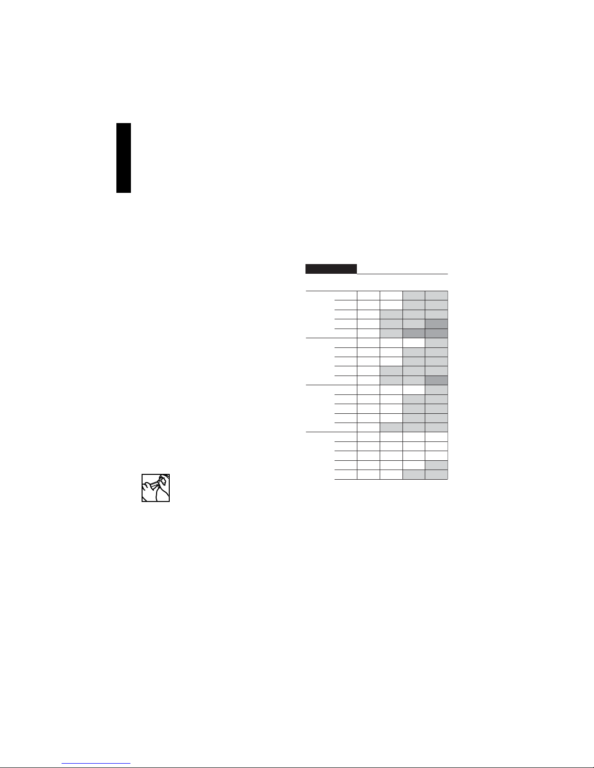
Cable Length Selection Tables
Table 1. Metal Pipe
Number of heating cable runs required
Metal Pipe
Thickness
1" 1 1 1 2
1 1/2" 1 1 1 1
Lowest Expected Temperature
Pipe SizeInsulation
20°F
0°F
(–20°C)
–20°F
(–30°C)
(–10°C)
1/2"1/2" 1 1 2 2
3/4" 1 1 2 2
1" 1 2 2 2
1 1/4" 1 2 2 3
1 1/2" 1 2 3 3
1/2"3/4" 1 1 1 2
3/4" 1 1 2 2
1" 1 1 2 2
1 1/4" 1 2 2 2
1 1/2"
3/4"
1"
1 1/4"
1 1/2"
2"
3/4"
1"
1 1/4"
1 1/2"
2"
1223
1122
1122
1122
1222
1111
1111
1112
1122
–40°F
(–40°C)
1A. Collect the necessary information.
You will need to know the following:
• Type of pipe (plastic or metal).
• Length and diameter of pipe.
• Lowest expected air temperature (disregard windchill).
• Number of valves and spigots (requires additional heating
cable).
• If there is a crock (typically used for manufactured housing
applications).
2
Page 5

Table 2. Plastic Pipe
Number of heating cable runs required
Plastic Pipe
Thickness
1" 1 1 2 2
1 1/2" 1 1 1 2
Lowest Expected Temperature
Pipe SizeInsulation
20°F
0°F
(–20°C)
–20°F
(–30°C)
(–10°C)
1/2"1/2" 1 2 2
3/4" 1 2 2 3
1" 1 2 3 3
1 1/4" 2 2 3
1 1/2" 2 3 3
1/2"3/4" 1 2 2 2
3/4" 1 2 2 3
1" 1 2 2 3
1 1/4" 1 2 3 3
1 1/2"
3/4"
1"
1 1/4"
1 1/2"
2"
3/4"
1"
1 1/4"
1 1/2"
2"
233
1122
1223
1233
1233
1122
1122
1122
1223
–40°F
(–40°C)
= Increase insulation thickness
1C. Calculate the total length of heating cable
required.
Multiply the number of heating cable runs by your pipe length.
Add one extra foot (30 cm) for each valve in your line. Add one
extra foot (30 cm) for the distance to the power connection. For
installations in a crock, add an additional 2 feet (60 cm) of
heating cable. After cutting the Frostex heating cable to the
length you need, proceed to Step 2.
The total length of heating cable equals:
32 ft (10 m) 2 runs x 16 ft (5 m) of pipe
+ 1 ft (0.3 m) for one ball valve
+ 1 ft (0.3 m) for one power connection
+ 2 ft (0.6 m) for installing in a crock
Total length = 36 ft (11 m)
Note: Do not use more than 50 feet (15 meters) of heating
cable per plug. If the total calculated length exceeds 50 feet
(15 meters), you will need additional 9800 FlexFit plugs and
outlets. Longer circuit lengths will blow the nonreplaceable
fuse in the 9800 FlexFit plug. If you require more than 50 feet
per length (15 meters), call Tyco Thermal Controls for information on other products.
ENGLISH
Example:
Pipe size and material: 1 inch diameter, plastic
Lowest ambient temperature: -20°F (-30°C)
Pipe length: 16 feet (5m)
Valves: 1 ball valve is used
The water connection is in a crock.
From Table 2, Plastic Pipe, for -20°F (-30°C), either two or
three runs of Frostex heating cable is required depending on
pipe insulation thickness.
Optimal Pipe insulation thickness: 3/4"
Selecting 3/4" thick insulation requires two runs of Frostex
heating cable installed along the entire length of the pipe (Table
2).
3
Page 6

Step 2.
Install the end seal.
Note: The end seal can only be used once, so do not install it until step 2D.
ENGLISH
Heating Cable Construction
2A. Prepare the heating cable.
Cleanly cut off one end of the heating cable.
2C. Remove the plastic wrap.
1"
(25 mm)
Clear plastic
wrap
Braid Blue jacket
2B. Push the braid back.
Push the braid back 1" (25 mm) from heating cable end.
2D. Install the end seal.
Black core
(bus wires inside)
1"
(25 mm)
Cut and remove the clear plastic wrap. Do not cut into the
blue jacket.
2E. Secure the braid.
Slide the braid up against the end seal and wrap it securely with
a 4" (10 cm) strip of glass fiber or vinyl tape.
Firmly push the end seal at least 3/4" (2 cm) onto the heating
cable. Some gel may ooze out.
10
in
10 2010 20
0
mm
4
Page 7

Step 3.
Back wall
Indicator
post
Install the 9800 FlexFit plug.
ENGLISH
Reset button
Test button
Ground-fault
unit
Ga
rder a
K
eep
d
ry
T
E
ST
u s
ec
Indicator
light
Cable guide
Ground contact
3A. Prepare the cable.
3/4"
(2 cm)
Cleanly cut off the end of the cable. Push back the braid 3/4" (2
cm) and then twist the end of the braid around the cable to
ensure the braid strands are not sticking up.
Note: The clear plastic wrap does not need to be removed.
3C. Complete the connection.
Cover
Back wall
Indicator post
3B. Insert the cable.
Insert the heating cable all the way into the cable guide until the
cable hits the back wall.
Be sure no braid wire strands enter cable
guide.
3D. Install the cover.
Screw down the cable guide, alternating between the two
screws, until the cable guide is flush with the indicator posts
and the screws bottom out.
0
in
01
cm
Install the cover by tightening the screws completely.
Note: The screws will require many turns before the cover
starts to close.
3/4
2
5
Page 8

Step 4.
Attach the heating cable to the
pipe.
ENGLISH
4A. Prepare to install the heating cable.
Begin the installation at the electrical outlet. Leave at least
1 foot (30 cm) of extra heating cable so the ground-fault unit
can be secured to the outside of the thermal insulation, as
shown in Figures 1 and 2. This will relieve any strain on the
heating cable or plug. However, be careful not to leave heating
cable hanging in a loose loop where it could be accidentally
snagged and pulled out.
Make certain you have removed any old heating tapes and
insulation.
Important: The ground-fault unit and plug must be kept dry.
It is important to include the drip loop to prevent water from
getting into the ground-fault unit.
Outlet
cover
9800
Flexfit
plug
Drip loop
Thermal
insulation
Cable ties
or tape
Multiple run method
When two or more runs are required, install the heating cable in
the 4 o’clock and 8 o’clock positions as shown in Figure 4.
When three runs are required, install the heating cable as
shown in Figure 5.
12
84
84
Figure 4. Double runs. Figure 5. Triple runs.
4C. Tape the heating cable and end seal to the pipe.
• Fasten the heating cable to the pipe at 1-foot (30-cm)
intervals, using two or three thicknesses of 9610 application tape or equivalent.
• Provide extra heat at valves and spigots by wrapping each
with 1 foot (30 cm) of additional heating cable, overlapping as required.
• If you have excess heating cable at the end of your pipe,
double it back along the pipe where the insulation will
completely cover it as shown in Figure 6. Using 9610
application tape or equivalent, tape the end seal to the pipe
as shown in Figures 1, 2, and 6.
Outlet
cover
End seal
End seal
Figure 1. Typical manufactured housing installation.
Figure 2. Typical installation.
4B. Install the heating cable.
Single run method
Run the heating cable in a straight line approximately a third of
the way up from the bottom of the pipe, as shown in Figure 3.
Frostex 9610
application tape;
1-foot spacing
Figure 3. Single run method.
9800
FlexFit
plug
Drip loop
Ground
level
Pipe
Crock
Cable ties
or tape
Thermal
insulation
Figure 6. Multiple run installation.
Important: In a crock or standpipe, run the Frostex heating
cable down and back up the pipe (as shown in Figure 6), so
that the end seal is well above the ground level and
will not be sitting in water.
6
Page 9

Step 5.
Install the insulation.
• The signal light will go on indicating that the ground-fault
protection device and the fuse are working properly.
However, the light does not confirm that the heating cable
is properly connected. See Step 7, “Test the System.”
ENGLISH
Thermal insulation must be used. It protects the Frostex heating cable from damage and helps keep the pipes from freezing.
Before you insulate, be sure the Frostex heating cable is
undamaged—no nicks or cuts—and the braid is intact.
Replace the heating cable if necessary.
5A. Cover the system with the insulation.
Cover the pipe, heating cable, connections, valves, and spigots
with clean, dry, waterproof, fire-retardant thermal insulation,
such as closed-cell foam insulation, as shown in Figure 7. The
insulation must be at least as thick as selected in Table 1 or 2.
Secure the 9800 FlexFit plug to the insulation with tape or
plastic cable ties, being careful not to cover the light or test
buttons.
Warning
labels
Figure 7. Thermal insulation.
• Do not leave the heating cable exposed, except for the
short distance from the pipe to the power connection.
• Fully insulate and weatherproof all exposed piping. Put
additional insulation on areas that cannot be heat traced.
5B. Waterproof the insulation.
Make sure the thermal insulation is waterproof and stays dry.
Install a watertight sleeve and a solid cover or a barrier such as
polyethylene sheeting around the insulation wherever there is
any chance that the insulation might get wet.
5C. Install the warning label.
Install the orange warning labels on the insulation with one
near the electrical outlet, as shown in Figure 7.
Additional labels and installation tape are available from Tyco
Thermal Controls in the Frostex 9610 kit.
Step 6.
Start up the system.
6B. Test the plug.
• Press the white test button. The red reset button should
pop out from the surface of the plug and the signal light
should go out.
• When the red reset button pops out, push it in to restore
power and proceed to Step 7.
If the red reset button fails to pop out,
“Troubleshooting.”
If the red reset button pops out immediately but cannot
be reset,
skip to “Troubleshooting.”
If the signal light does not light,
skip to
skip to “Troubleshooting.”
Step 7.
Test the system.
Test the system using one of the two following procedures.
7A. Test the water temperature.
After plugging in the system, wait about an hour. Turn on a
water tap on the Frostex-protected pipe and test the temperature of the water. It should feel warm almost immediately
because the water heated by the Frostex heating cable will be
briefly running through the pipe.
If the water is warm,
If the water is not warm,
7B. Test the heating cable’s resistance.
It is possible to test the resistance of Frostex heating cable
using a multimeter. Follow these steps:
• Be sure the 9800 FlexFit plug is unplugged.
• Push in the red reset button on the plug.
• Connect the two lead wires on the meter to the two flat
prongs on the plug. The meter reading should be between
2 and 20,000 ohms.
If your reading is within this range,
the installation.
If your reading is not within this range,
“Install the 9800 FlexFit plug” and retest.
If your reading is still not within this range or you
have questions,
cal support at (800) 545-6258.
you have completed the installation.
skip to “Troubleshooting.”
you have completed
repeat Step 3,
call Tyco thermal controls for techni-
6A. Plug in the heating cable.
After installing the heating cable and insulation, remove the
clear label that covers the test and reset buttons. Then, plug the
9800 FlexFit plug into a grounded and properly installed outlet.
• If the Frostex heating cable length is longer than 40 feet
and the air temperature is lower than 30°F, run water
through the pipe before plugging in the unit. This will
warm up the pipe and help avoid blowing the nonreplaceable fuse in the 9800 FlexFit plug.
7
Page 10

Periodic Inspections
Troubleshooting
Each month
• Test the 9800 FlexFit plug as described in Step 6B.
Periodically
ENGLISH
Each time you plug in the system, and at least once a year,
do the following:
• Check the entire Frostex system for signs of damage.
Inspect any exposed portion of the heating cable for
evidence of cuts, nicks, abrasions, gnawing by animals,
and any other physical damage.
If there is damage, immediately replace the damaged
heating cable system and thermal insulation. Do not
attempt to repair any part of the heating cable system.
• After a thorough inspection, start up the system and test the
9800 FlexFit plug and system as described in Steps 6 and 7.
Problem: The red button pops out immediately when
the plug is plugged in, or the button will not reset.
What to do: A strand of braid may have entered the heating cable
guide during Step 3B.
• Unplug the 9800 FlexFit Plug.
• Remove the cover (the reverse of Step 3D).
• Unscrew the two screws of the heating cable guide (the
reverse of Step 3C).
• Using a flat blade screwdriver, gently pry the heating cable
guide up until the heating cable can be removed.
• Reinstall the screws completely into the heating cable guide
before re-attaching.
• Repeat installation steps 3A–3D, ensuring no braid strands
enter the heating cable guide during Step 3B.
• Repeat Step 6, “Start up the system.”
Note: If the 9800 FlexFit Plug red test button continues to pop
out, your system is damaged and must be replaced.
Problem: The signal light does not light up.
What to do: Check to be sure the outlet has power. If you are
not certain how to do this, call a professional service person.
If the outlet has no power,
“Start up the system.”
correct the problem, then follow Step 6,
If the outlet has power but the signal light still does not light up after
you conduct the test described in Step 6B, “Test the plug,” the
internal nonreplaceable fuse is blown. This means the Frostex
system is damaged and must be replaced.
Problem: The 9800 FlexFit plug does not trip
(red button does not pop out).
What to do: Check to be sure the outlet has power. If you are
not certain how to do this, call a professional service person.
If the outlet has no power,
instructions in Steps 6 and 7.
correct the problem, then follow the
If the outlet has power but the 9800 FlexFit plug still fails to trip,
the Frostex system is damaged and must be replaced.
Problem: The heating cable fails to warm up or water
is not warm after testing the system.
What to do: The heating cable may not be fully inserted into the
heating cable guide, or the guide may not be screwed down completely.
• Unplug the 9800 FlexFit Plug.
• Remove the cover (the reverse of Step 3D).
• Unscrew the two screws of the heating cable guide (the
reverse
of Step 3C).
• Using a flat blade screwdriver, gently pry the heating cable
guide up until the heating cable can be removed.
• Reinstall the screws completely into the heating cable guide
before re-attaching.
• Repeat installation steps 3A–3D, ensuring no braid strands
enter the heating cable guide during Step 3B.
• Repeat Step 6, “Start up the system.”
8
Page 11

Limited Warranty
Tyco Thermal Controls warrants all Frostex
self-regulating heating cables and components against faulty workmanship and use
of defective materials for two (2) years
from the date of purchase. This warranty
can be amended only by a written instrument signed by a duly authorized officer of
Tyco Thermal Controls. Buyer's exclusive
remedy under this warranty shall be to
have Tyco Thermal Controls, within a reasonable time, repair such goods or supply
replacement goods or credit Buyer's
account for such goods and accept their
return whichever Tyco Thermal Controls
may elect at its sole discretion. Tyco
Thermal Controls shall in no event be liable
for the cost of removal or installation, for
loss or damage to or loss of use of facilities or other property, loss of revenue, loss
of use of revenue, loss of anticipated profits, or other damages or costs of any kind
whatsoever, whether direct, indirect, incidental, or consequential.
Notwithstanding the foregoing, Tyco
Thermal Controls shall have no liability
whatsoever unless: (a) Buyer promptly
notifies Tyco Thermal Controls in writing
after discovery of an alleged nonconformity
and includes a detailed explanation of the
alleged nonconformity; (b) Buyer promptly
returns the goods to Tyco Thermal
Controls postage prepaid, at 300
Constitution Drive, Menlo Park, California
94025-1164, USA; and (c) Tyco Thermal
Controls examination of such goods establishes to Tyco Thermal Controls satisfaction that such alleged nonconformities
actually exist and occurred in the cause of
proper and normal use and were not
caused by accident, misuse, neglect, alteration or improper installation, repair or
testing or such other cause outside of the
responsibility of Tyco Thermal Controls
under this Limited Warranty.
THE FOREGOING WARRANTY IS IN LIEU
OF ALL OTHER REPRESENTATIONS, WARRANTIES, OR CONDITIONS, EXPRESS OR
IMPLIED, INCLUDING WITHOUT LIMITATION ANY IMPLIED WARRANTY OF MERCHANTABILITY, FITNESS FOR A PARTICULAR PURPOSE OR NONINFRINGEMENT,
AND OF ANY OTHER OBLIGATION OR LIABILITY ON THE PART OF TYCO THERMAL
CONTROLS, WHETHER BY STATUTE,
CONTRACT, STRICT LIABILITY, TORT OR
OTHERWISE.
If the goods are a consumer product in
buyer's jurisdiction, the above exclusion or
limitation of incidental or consequential
damages and the above disclaimer of
implied warranties may not apply. The term
of any such implied warranty is limited to
the term of this two-year Limited Warranty.
Some jurisdictions do not allow limitations
on how long an implied warranty lasts, so
the above limitation may not apply. This
warranty gives consumers specific legal
rights, and consumers may also have other
rights, which vary by jurisdiction.
ENGLISH
9
 Loading...