

Page 1
TECHNICAL SPECIFICATION
Type IdentificationValue: 181
Overall DimensionswithFascia Plate
Height: 87mm
Width: 148mm
Depth: 14mm
Weight: 100g
Material
Housing: BAYBLEND
(Polycarbonate ABS alloy)
Environmental:
Operating Temperature: -10
o
Cto+55oC
Storage Temperature: -40
o
Cto+80oC
Relative Humidity: Up to 95% non-condensing
Electrical Characteristics
Battery Requirements from Address
-
able Loop:
Fireray 50/100:
Standby: 5mA max
Alarm: 16mA max
Overload Current: 35mA max
Electromagnetic Compatibility
The FC410BDM complies with the following:
product family standard EN50130-4 in respect of Conducted Disturbances, Radi
ated Immunity, Electrostatic Discharge, Fast Transients and Slow High Energy;
EN50081-1 for emissions.
INTRODUCTION
The FC410BDM Beam Detector Interface Module is designed to interface
FIRERAY 50/100 Beam Detectors listed in this document to the FC Digital
Addressable Loop (it must not be used with other types of beam detector).
The FC410BDM monitors the Fire and Fault contacts and also monitors for
open and short circuits on the connections between the interface and the
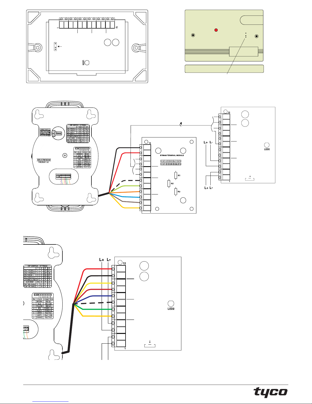
beam detector. For remote siting of the Fireray 50/100 an optional BTM800
Terminal Module can be used with 4 core cable.
The FIRERAY 50 and 100 transmitter and receiver units are mounted in the
same housing.
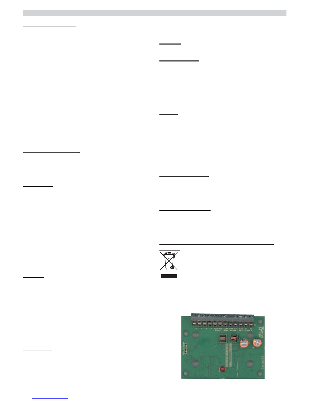
The FC410BDM Loop Powered Beam Detector Interface Module is con
tained on a double sided printed circuit board (PCB) which is fitted into a
custom built fascia plate with a protective cover being fitted over the PCB,
leaving only theconnection terminals exposed. Thefascia plate isthen fitted
onto a standard dual-gang back box with BESA fittings.
FEATURES
The FC410BDMBeamDetector module is capableof monitoring and signal
ling the following beam detector conditions:
Ø
Normal condition
Ø
Alarm condition
Ø
Device fault
Ø
Device wiring open circuit
Ø
Device wiring short circuit
Ø
Power wiring fault
The LED will illuminate when the control panel has determined that the
FC410BDM is in an alarm condition.
The LEDpulseswhenthe FC410BDM isaddressedfrom the control panel.
WIRING NOTES
The following notes apply:
1) There are no user-required settings (switches, headers) on the FC410BDM.
2) All wiring must conform to the applicable standards.
3) All conductors to be free of earths.
4) Connect thewiring to theFireray detector. For FC410BDM typical wiring
configurations (see Figures 4 to 5).
5) Verify the correct polarity of wiring before connecting the FC410BDM to
the addressable loop circuit.
MOUNTING
Fit cover to backbox.
ADDRESS SETTINGS
The FC410BDM has adefault factory set addressof 255, this must be set to
the loop address of the device using the FC490ST Loop Service Tool. The
FC410BDM maybe programmed withthe address priorto being installedby
using the internal programming port (see Fig.2) or after being installed by
using the programming port on the front cover (see Fig.3).
+
Note: Once the address has been programmed, take note of the device
location and address number, to include on site drawings.
CABLING
Cables are to be selected in accordance with the system design document
and the requirements of the applicable standard. Two pairs of connection
terminals (L+ and L-) are provided on the terminal block. These terminals
are used for connecting the module on to the addressable circuit. The maxi
-
mum section of the cable that can be connected at any one terminal is
2.5mm
2
. The section is calculated based on the characteristics of the cable
and the load.
Fig. 4showsthe Fireray 50/100connectedviaa BTM800 Terminal Module.
Fig. 5 shows the Fireray 50/100 wiring diagram.
ORDERING INFORMATION
FC410BDM: Beam Detector Module c/w Cover
BTM800: Beam Terminal Module c/w Cover
Fireray 50: 5-50 Metres Reflective Beam Smoke Detector 12V-24V dc
Fireray 100: 50-100 Metres ReflectiveBeamSmoke Detector 12V-24Vdc
RECYCLING INFORMATION
Customers are recommended to dispose of their used equipments (panels, detectors, sirens, and other devices) in an environmentally sound manner. Potential methods include reuse of parts or whole products and recycling of products,
components, and/or materials.
WASTE ELECTRICAL AND ELECTRONIC EQUIPMENT (WEEE)
DIRECTIVE
In the European Union, this label indicates that this product
should NOTbe disposed of with household waste. It should be
deposited at an appropriate facility to enable recovery and re
-
cycling.
The manufacturer reserves the right to change the technical specifications
of this product without prior notice.
ENGLISH
FIG. 1 FC410BDM Beam Detector Module
Page 2
PORTA DI PROGRAMMAZIONE
PROGRAMMING PORT
PROGRAMMIERANSCHLUSS
L+ L– L+ L– – +
N/O N/C COM COM N/C N/O
FAULT(MON) ALARM (RTN) SUPPLY
FIG. 2 FC410BDM fissata al coperchio-
FC410BDM ins Gehäuse eingebäut
FC410BDM with Cover Removed
PORTA DI PROGRAMMAZIONE
ADDRESS SETTING PORT
PROGRAMMIERAN
S
CHLU
SS
FIG. 3 FC410BDM Placca -
Kurzschlussisolator Vorderseite
FC410BDM Facia Plate
PORTA DI PROGRAMMAZIONE
ADDRESS SETTING PORT
PROGRAMMIERANSCHLUSS
BTM800 MODULO TERMINALE
BTM800 TERMINAL MODULE
FC LINEARRAUCHMELDER-ANSCHLUSSMODUL - BTM800
FC410BDM MODULO PER RIVELATORE
LINEARE DI FUMO
FC410BDM BEAM DETECTOR MODULE
FC LINEARRAUCHMELDER-MODUL - FC410BDM
YELLOW
BROWN
BLUE
ORANGE
GREEN
WHITE
RED
BLACK
N/O N/C COM N/O N/C COM MON RTN + – + –
ALARM FAULT SUPPLY
L+
L– L+ L– N/O N/C COM COM N/C N/O – +
FAULT (MON) ALARM (RTN) SUPPLY
Schema di collegamento FC410BDM con BTM800 e Fireray 50/100
Anschluss des BTM800 an das BDM800 und an das FIRERAY 50/100
FIG. 4 - BTM800 to FC410BDM Wiring for Remote Sitingof Fireray50/100 BeamDetectors
FC410BDM MODULO PER RIVELATORE LINEARE DI FUMO
FC410BDM BEAM DETECTOR MODULE
FC LINEARRAUCHMELDER-MODUL - FC410BDM
PORTA DI PROGRAMMAZIONE
ADDRESS SETTING PORT
PROGRAMMIERANSCHLUSS
L+
L– L+ L– N/O N/C COM COM N/C N/O – +
FAULT (MON) ALARM (RTN) SUPPLY
YELLOW
BROWN
BLUE
ORANGE
GREEN
WHITE
RED
BLACK
FIG. 5 Schema di collegamento FC 410BDM con Fireray 50/100
Fireray 50/100 Simplified Wiring Diagram
Anschluss des FC410BDM an das FIRERAY 50/100
© FireClass
Via Gabbiano 22, Z.Ind.S. Scolastica
64013 Corropoli (TE), Italy
Hillcrest Business Park Cinderbank
Dudley West Midlands
DY2 9AP United Kingdom
www.fireclass.co.uk
FireclassSales@tycoint.com
 Loading...