

Page 1
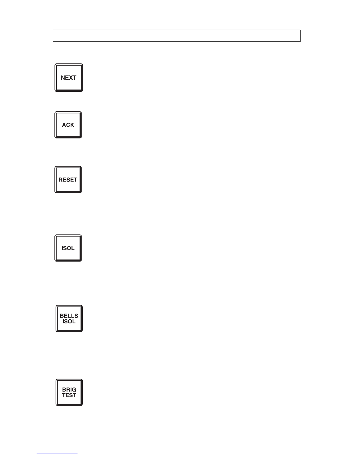
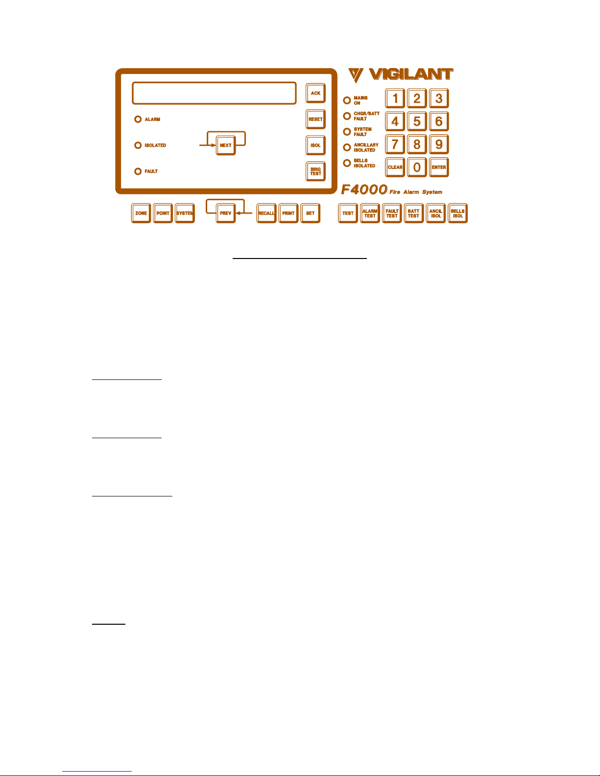
FIRE FIGHTER'S GUIDE - FFCIF TYPE 3
1. VIEW NEXT ALARM
Press "NEXT" key once -
- The LCD will display the next alarm.
2. ACKNOWLEDGE DISPLAYED ALARM
Press "ACK" key once.
- LCD will display "ACKD" for the displayed alarm.
- The flashing alarm LED for the zone will go steady.
- If all alarms are acknowledged, the ALARM LED will go steady.
3. RESET ALL ACKNOWLEDGED ALARMS
Press "RESET" key once.
- LCD will display "Resetting acknowledged alarms".
- Alarm LEDs for acknowledged alarms will turn off.
- If all alarms are reset, the LCD will display
"No more events in alarm list", otherwise the oldest unacknowledged
alarm will be displayed.
4. ISOLATE ALL ACKNOWLEDGED ALARMS
Press "ISOLATE" key once.
- LCD will display "Isolating acknowledged alarms".
- Isolate LEDs for acknowledged alarms will turn on.
- If all alarms are isolated, the LCD will display "No more events in
alarm list", otherwise the oldest unacknowledged alarm will be
displayed.
5. ISOLATE/DE-ISOLATE BELLS
Press "BELLS ISO" key once.
- If the "Bells Isolate" LED is OFF
- The "Bells Isolate" LED will turn ON steady.
- The bells will turn OFF if they are ON.
- If the "Bells Isolate" LED is ON
- The "Bells Isolate" LED will turn OFF.
- If any un-isolated alarms exist, the bells will ring.
6. BRIGADE TEST
Press and hold the "BRIG TEST" key for at least 2 seconds. If enabled:
- The FIP will signal Alarm to the brigade.
- Any ancillary functions controlled by MAF ALARM will turn ON, unless
they are isolated.
Page 2

THIS PAGE INTENTIONALLY LEFT BLANK
Page 3

F4000
LCD OPERATOR'S MANUAL
F4000 PRODUCT MANUAL
VOLUME 7
Document Number: LT0117
Issue 2.38; 19 April 2002
- APPROVALS -
AUSTRALIAN STANDARDS AS1603.4 1987 (Incl. Amdt 1 & 2):
- SSL Certificate of Compliance Number 131
- SSL Register of Accredited Products Number 398 (Fire Protection Equipment)
AUSTRALIAN STANDARDS AS4050(INT) 1992
NEW ZEALAND STANDARDS NZS4512-1981 (INCL AMDT 1 & 2)
AS/NZS 3548 1995 CLASS A
The F4000 Fire Indicator Panel is manufactured for:
Tyco Services Fire & Safety
25 Cleeland Road
Oakleigh South
VIC 3167
AUSTRALIA
Tel : +61-3-9543 2220
Fax : +61-3-9543 2155
COPYRIGHT (C) 1995, 1996, 1997, 1998, 2000, 2001, 2002
Information contained in this document is subject to copyright, and shall not be reproduced in any
form whatsoever, without the written consent of Tyco Services Fire & Safety.
Information contained in this document is believed to be accurate and reliable, however Tyco
Services Fire & Safety reserves the right to change the content without prior notice.
Page 4

F4000 LCD Operator's Manual Document No: LT0117
Page ii 19 April 2002 Issue 2.38
INSTALLATION DETAILS
For your reference please complete the following information on the F4000 LCD Fire
Indicator Panel supplied.
F4000 FIP SUPPLIED BY
F4000 FIP INSTALLATION LOCATION
CONTRACT/JOB NUMBER
F4000 SERIAL NUMBER
F4000 SYSTEM AS INSTALLED
DRAWING NUMBER Issue:
F4000 SYSTEM PARAMETERS
DRAWING NUMBER Issue:
Date Panel Manufactured
Date Panel Installed
Date Panel Commissioned
Maintenance Company
Telephone B.H. A.H.
Service Contact
Site Contact or Registered User
(include title)
Company / Address
Telephone B.H.
EMC COMPLIANCE
WARNING: This product is a Class A product. In a domestic environment this product
may cause radio interference in which case the user may be required to take
adequate measures.
Page 5

Document No: LT0117 F4000 LCD Operator's Manual
Issue 2.38 19 April 2002 Page iii
TABLE OF CONTENTS
Installation Details………………………………………………………………………………. ii
End User Liability Disclaimer……………………………………………………… v
Amendments…………………………………………………………………………………….. vi
1 INTRODUCTION .......................................................................................... 1-1
1.1 SCOPE.................................................................................................................. 1-2
1.2 ATTACHMENTS ................................................................................................... 1-3
1.3 ASSOCIATED DOCUMENTATION ...................................................................... 1-4
1.4 GLOSSARY OF TERMINOLOGY......................................................................... 1-6
2 SYSTEM DESCRIPTION ............................................................................. 2-1
2.1 SYSTEM COMPONENTS..................................................................................... 2-2
2.2 LCD FIP DISPLAYS............................................................................................ 2-10
2.3 LCD KEYPAD INTRODUCTION......................................................................... 2-12
2.4 AUDIBLE TONES ............................................................................................... 2-18
2.5 NETWORKED PANELS...................................................................................... 2-19
3 SYSTEM SPECIFICATIONS........................................................................ 3-1
3.1 SYSTEM CAPACITY ............................................................................................ 3-2
3.2 PHYSICAL ............................................................................................................ 3-3
3.3 ELECTRICAL ........................................................................................................ 3-6
3.4 INDICATORS ........................................................................................................ 3-7
3.5 KEYPAD CONTROLS........................................................................................... 3-8
4 INTERPRETING THE DISPLAY .................................................................. 4-1
4.1 RESPONDING TO ALARMS ................................................................................ 4-2
4.2 DEALING WITH FAULTS ..................................................................................... 4-3
4.3 SYSTEM INDICATORS ........................................................................................ 4-4
4.4 ZONE INDICATORS ............................................................................................. 4-8
4.5 LED PHASING ...................................................................................................... 4-9
Page 6

F4000 LCD Operator's Manual Document No: LT0117
Page iv 19 April 2002 Issue 2.38
4.6 CONTROL OF FIP BY MULTIPLE OPERATORS .............................................. 4-10
5 OPERATING INSTRUCTIONS - BRIGADE FUNCTIONS........................... 5-1
5.1 INTRODUCTION TO BRIGADE FUNCTIONS...................................................... 5-2
5.2 SILENCING THE INTERNAL SOUNDER............................................................. 5-4
5.3 ACKNOWLEDGE ZONES IN ALARM .................................................................. 5-5
5.4 RESET ACKNOWLEDGED ZONES IN ALARM................................................... 5-6
5.5 ISOLATE ACKNOWLEDGED ZONES IN ALARM................................................ 5-7
5.6 ISOLATING/DE-ISOLATING BELLS .................................................................... 5-8
5.7 DISPLAYING THE ALARM CAUSE...................................................................... 5-9
5.8 EXITING FFCIF MODE....................................................................................... 5-10
5.9 RECALLING THE ALARM LIST.......................................................................... 5-11
5.10 BRIGADE TEST................................................................................................. 5-12
6 OPERATING INSTRUCTIONS - SYSTEM FUNCTIONS............................. 6-1
6.1 BATTERY TEST ................................................................................................... 6-2
6.2 BELL TEST ........................................................................................................... 6-4
6.3 BELL ISOLATE OR DE-ISOLATE ........................................................................ 6-5
6.4 LCD/LAMP (LED) TEST........................................................................................ 6-6
6.5 SYSTEM TEST ..................................................................................................... 6-7
6.6 RECALL SYSTEM FAULTS................................................................................ 6-10
6.7 SYSTEM FAULT RESET .................................................................................... 6-14
6.8 RECALL HISTORY ............................................................................................. 6-15
6.9 SET SYSTEM TIME............................................................................................ 6-17
6.10 SET SYSTEM DATE.......................................................................................... 6-18
6.11 SET LCD ACCESS PASSWORD ...................................................................... 6-19
6.12 GLOBAL RESET................................................................................................ 6-20
6.13 GLOBAL ISOLATE............................................................................................. 6-21
6.14 RECALL SYSTEM CRCS .................................................................................. 6-22
Page 7

Document No: LT0117 F4000 LCD Operator's Manual
Issue 2.38 19 April 2002 Page v
7 OPERATING INSTRUCTIONS - ZONE FUNCTIONS.................................. 7-1
7.1 ZONE ALARM OR FAULT TEST.......................................................................... 7-2
7.2 ZONE OR ANCILLARY ISOLATE OR DE-ISOLATE ............................................ 7-6
7.3 ANCILLARY TEST .............................................................................................. 7-11
7.4 ZONE OR ANCILLARY RESET.......................................................................... 7-13
7.5 AUTO-RESET MODE ......................................................................................... 7-15
7.6 ZONE STATUS RECALLS.................................................................................. 7-18
8 OPERATING INSTRUCTIONS - POINT FUNCTIONS................................. 8-1
8.1 ANALOGUE RECALLS......................................................................................... 8-2
8.2 ANALOGUE DETECTOR HISTORY, TRACKING, DEVICE RESET.................. 8-10
8.3 SETTING DETECTOR SENSITIVITIES.............................................................. 8-11
8.4 POINT ISOLATION ............................................................................................. 8-16
9 PLACING INTO OPERATION...................................................................... 9-1
9.1 GENERAL ............................................................................................................. 9-2
9.2 MAINS ISOLATE SWITCH ................................................................................... 9-3
9.3 POWER UP........................................................................................................... 9-3
9.4 COMMISSIONING CHECKLIST ........................................................................... 9-4
10 SYSTEM MAINTENANCE & TROUBLE SHOOTING.................................10-1
10.1 SYSTEM MAINTENANCE ................................................................................. 10-2
10.2 TROUBLE-SHOOTING...................................................................................... 10-5
APPENDIX A …………………………………………………………………………. A-1
APPENDIX B …………………………………………………………………………. B-1
APPENDIX C …………………………………………………………………………. C-1
Page 8

F4000 LCD Operator's Manual Document No: LT0117
Page vi 19 April 2002 Issue 2.38
TYCO SERVICES FIRE & SAFETY
END USER LIABILITY DISCLAIMER
The F4000 Fire Indicator Panel provides a configuration programming facility, which may be
accessed via a programming terminal using a password.
Because this programming facility allows the user to define in detail the operation of the
F4000 System which is being customised, changes may be made by the user that prevent
this installation from meeting statutory requirements.
TYCO SERVICES FIRE & SAFETY
therefore cannot accept any responsibility as to the
suitability of the functions generated by the user using this programming facility.
Page 9

Document No: LT0117 F4000 LCD Operator's Manual
Issue 2.38 19 April 2002 Page vii
AMENDMENTS
ISSUE DATE COMMENTS ECN
1 10/09/93 Original for Software Version 2.0
1.1 03/11/93 Minor Text Changes/Updates
2.2 15/12/95 Updated for Software Version V2.2X and V2.2XN.
Includes:
Support for "130 Series" Devices.
New Analogue Sensitivity Adjustment.
New Fault Present and Database.
Change/CRC Display.
2.22 25/07/96 Updated for V2.22/2.22N software, updated pages i, vi, 4-3,
4-7, 5-8, 6-5, 6-11, 6-12.
2468
2.23 24/10/96 Updated for V2.23/V2.23N, pages i, iv, vi, 4-5, 6-11, 6-12
and Chapter 8.
2510
2.23A 10/04/97 Bell Test Key Sequence corrected (was Sys Test 2). 2602
2.30 14/10/97 Updated for V2.30/V2.30N
Sections 0, 1, 2.1.7, 2.1.9, 2.1.11, 2.3.1, 2.3.5, 2.4, 3.1,
3.2.6, 5.1.2, 5.7.2, 6.6.3, 6.9.3, 7.6.2, 7.6.3, 8.3.1, 8.3.4,
8.4.2, Appendix A, Table III base information, pg A-5 6)
2621
2.31 27/04/98 Updated for V2.31/V2.31N.
Sections 2.4, 3.3, 4.3.5, 6.1.3, 6.4, 6.6.3, 9.3
2.35 01/02/00 Updated for V2.35/V2.35N, converted to Word 97, Sections
1.1, 1.3, 1.4, 2.3.1, 2.3.8, 4.6, 5.1.2, 5.2.1, 5.6.1, 5.7.2,
5.9.2, 6.6.3, 6.4, 6.9, 8.1.2, 8.1.3, 8.1.4, 8.1.5, 8.2.3.
Added 8.1.6. Updated Fire Fighter’s Type 3 Guide.
2983
2.35A 02/05/00 Revised to include networking features from LT0150. 3074
2.37 19/04/01 Brand changed to Tyco. Revised Section 5.2.1 and added
P133A, Z134A details to Appendix A.
3169
2.38 19/04/02 Revised for V2.38 for Dirty Alert, Charger Ignore time after
NZ 1 hour battery test, and Charger LED cadence.
3288
Page 10

F4000 LCD Operator's Manual Document No: LT0117
Page viii 19 April 2002 Issue 2.38
THIS PAGE IS INTENTIONALLY LEFT BLANK
Page 11

Document No: LT0117 F4000 LCD Operator's Manual
Introduction
Issue 2.38 19 April 2002 Page 1-1
1 INTRODUCTION
Page 12

F4000 LCD Operator's Manual Document No: LT0117
Introduction
Page 1-2 19 April 2002 Issue 2.38
1.1 SCOPE
The F4000 Fire Alarm System is very powerful and packed with many features. In spite of
this, it is very user friendly and intuitive to use.
The LCD front panel provides a simple, menu driven interface to allow control of the FIP and,
therefore, reference to this manual is rarely required for the experienced fire industry person.
This manual has been written to cover every aspect of the panel's operation and would
normally be consulted for reference purposes only, or when there are abnormal situations.
NOTE: This manual describes operation of F4000 FIPs fitted with Version V2.35N or later
software and an LCD keypad. Network operation is covered in this manual (it
previously was a supplementary manual) even though networking may not be
enabled in all panels. Operators of systems without an LCD should use LT0057,
as there are many differences in operation. Operators of systems with V2.0X
software should use revision 1.1 of this manual, and systems with V2.2(N) software
should use revision 2.23A of this manual.
For the less experienced user, start by reading the chapter on "System Description".
The building owner's representative responsible for the fire alarm system should be fully
aware of what is contained in this manual.
The Manual is structured into the following chapters:
Chapter 1: Introduction: An introduction to this manual, other F4000 Product manuals
and the standards relating to fire alarms.
Chapter 2: System Description; A description of the F4000 system features and
functions, and how networking alters a panel’s operation.
Chapter 3: Specifications; A summary of F4000 system specifications.
Chapter 4: Interpreting the Display; A description of display indications.
Chapter 5: Operating Instructions - Brigade Functions; A detailed description of the
operation and function of keys for FIRE FIGHTER'S USE provided on the
F4000 LCD ("ACK", "RESET", "ISOLATE" and "BRIG TEST").
Chapter 6: Operating Instructions - System Functions; A detailed description of the
operation and function of keys provided on the F4000 LCD FIP for system
testing and information recall. For example, System Test, Lamp (LED) Test,
System Fault Reset, Bell Test, Bell Isolate, and History recalls.
Chapter 7: Operating Instructions - Zone Functions; A detailed description of the
operation and function of keys provided on the F4000 LCD FIP for zone tests
and functions.
Chapter 8: Operating Instructions - Point Functions; A detailed description of the
operation and function of keys provided on the F4000 LCD FIP for point
recalls, and sensitivity adjustments.
Page 13

Document No: LT0117 F4000 LCD Operator's Manual
Introduction
Issue 2.38 19 April 2002 Page 1-3
SCOPE (CONTINUED)
Chapter 9: Placing Into Operation; A description of how to place a correctly aligned
and adjusted system into operation. Also included is a System
Commissioning Checklist.
Chapter 10: Maintenance and Trouble-Shooting; A guide on system maintenance
procedures and trouble-shooting.
Appendix A: Responder Compatible Actuating Devices; A list of compatible actuating
devices and detectors for the F4000 FIP.
Appendix B: Compatible Batteries; A list of compatible batteries.
Appendix C: FFCIF Type 2 Fire Fighters Guide; For use when the FIP is programmed for
FFCIF Type 2 operation.
1.2 ATTACHMENTS
A FIRE FIGHTER'S GUIDE is fixed inside the front cover for quick reference in
emergencies.
If the F4000 FFCIF is configured for Type 2 operation, i.e. global acknowledgement, reset
and isolation of zones in alarm, refer to Appendix C for instructions on ensuring that the
correct Fire Fighters Guide is used.
Your installation company should install the following documents inside the panel:
(a) An "AS INSTALLED" fire detection system diagram and/or summary, describing the
installed layout of your F4000 System.
(b) Other "AS INSTALLED" information, such as System configuration parameters.
(c) A Maintenance Log-Book.
Page 14

F4000 LCD Operator's Manual Document No: LT0117
Introduction
Page 1-4 19 April 2002 Issue 2.38
1.3 ASSOCIATED DOCUMENTATION
1.3.1 PRODUCT RELATED
The following F4000 product manuals are available:
Volume 1, F4000 Operator's Manual, provides a complete guide to the operation and
maintenance of the F4000 FIP and RZDU panels, with Version 1.X software, according to
Australian Standards AS1603 Part 4 and New Zealand Standard NZS4512. This manual is
provided as standard with non-LCD F4000 FIP panels, and RZDUs (LT0057).
Volume 2, F4000 Technical Manual, provides complete technical details on the F4000
system and Hardware/Software components, according to Australian Standards AS1603
Part 4, for servicing purposes (LT0069).
Volume 3, F4000 Engineering Manual, provides complete design details for correctly
engineering the F4000 system to meet customer and standard specifications (LT0071).
Volume 4, F4000 Installation Manual, provides complete details for correctly installing
and placing into operation the F4000 system (LT0070).
Volume 5, F4000 Programming Manual, provides details for correctly programming the
F4000 system to meet the system engineering specifications (LT0072).
Volume 6, F4000 AAR Technical & Engineering Manuals, Volume 6-1 provides
Technical details on the AAR and Addressable Devices, and Volume 6-2 provides
Engineering Design information for correctly engineering the AAR loop (LT0095/LT0096).
Volume 7, F4000 LCD Operator's Manual, provides a complete guide to the operation
and maintenance of F4000 LCD FIP panels with Version 2.X software, according to
Australian Standards AS1603 Part 4, AS4050(INT), and New Zealand Standard NZS4512.
This manual is provided as standard with F4000 LCD FIP panels (LT0117/LT0118).
From Issue 2.35A onwards LT0117 includes networked operation, previously covered in a
separate manual LT0150.
Volume 8, F4000 NZ Fire Indicator Panel Technical Manual, provides additional
installation and technical information regarding the application of F4000 Analogue
Addressable Fire Alarm Systems in
New Zealand (LT0126).
Volume 9, F4000 MPR Technical & Engineering Manuals, Volume 9.1 provides
technical details on the MPR and Addressable devices, and Volume 9-2 provides
Engineering Design information for correctly engineering the MPR loop (LT0139/LT0140).
Page 15

Document No: LT0117 F4000 LCD Operator's Manual
Introduction
Issue 2.38 19 April 2002 Page 1-5
1.3.2 STANDARDS RELATED
This manual makes reference to the following Australian Standards:
AS1603.4 Automatic Fire Detection and Alarm Systems
Part 4 - Control and Indicating Equipment
AS1670 Automatic Fire Detection and Alarm Systems-
System Design, Installation, and Commissioning.
AS1851.8 Maintenance of Fire Protection Equipment
Part 8 - Automatic Fire Detection and Alarm Systems.
AS4050(INT) Fire Detection and fire alarm systems - Fire Fighter's control and indicating
facilities.
This manual makes reference to the following New Zealand Standard:
NZS4512 Automatic Fire Alarm Systems in Buildings.
Page 16

F4000 LCD Operator's Manual Document No: LT0117
Introduction
Page 1-6 19 April 2002 Issue 2.38
1.4 GLOSSARY OF TERMINOLOGY
The following abbreviations and terminology are used in this manual:
AAR Analogue Addressable Responder
AC Alternating Current
ACZ Ancillary Control Zone
ADR Advanced Detector Responder unit
ADU Addressable Device Unit
"ALM" Display abbreviation for ALARM
ARR Advanced Relay (and Detector) Responder (ADR + RRM)
AS Ancillary Supervision
AVF Alarm Verification, or check alarm.
AZC Alarm Zone Circuit, commonly referred to as "Detection Zone"
AZF Alarm Zone Facility, commonly referred to as "GROUP"
CIE Control and Indicating Equipment
DC Direct Current
DIRTY ALERT Signalled when Detector contamination becomes excessive
EEPROM Electrically Erasable Programmable Read Only Memory
EOL End Of Line device
EPROM (U.V.) Erasable PROM
F Flashing LED indicator
FFCIF Fire Fighter's Control & Indication Facilities, AS4050 (INT)
FFCIF MODE The LCD is displaying the alarms list. Limited key entry as per AS1603.4
FIP Fire Indicator Panel
"FLT" Display abbreviation for FAULT
FRC Flat Ribbon Cable
FSZ Flowswitch Zone
GLOBAL A function that may affect more than one zone.
IOR Input Output Responder
"ISO" Display abbreviation for ISOLATED
LCD Liquid Crystal Display
LED Light Emitting diode (Visual Indicator)
LOGICAL A responder that communicates with the FIP. A physical responder may
RESPONDER function as a number of logical responders.
MAF Master Alarm Facility
MAF ZONE Any zone, Alarm or Ancillary Control, that is configured to signal the brigade
in the event of an alarm or fault
MAPPING Programming AZCs to turn on certain outputs
MCP Manual Call Point (break glass switch)
MAINTENANCE
ALERT Equivalent to Dirty Alert
MPR Multi-Protocol Responder
O/C Open Circuit
PCB Printed Circuit Board
PHYSICAL A single physical responder pcb connected to the loop, which may internally
RESPONDER support a number of logical responders.
PROM Programmable Read-Only Memory
PSU Power Supply Unit
RAM Random Access Memory
RF Rapid Flashing LED indicator
RRM Responder Relay Module
RZDU Remote Zone Display Unit
S/C Short Circuit
SF Slow Flashing LED indicator
VB Abbreviation for Battery Backed Voltage.
VNB Abbreviation for Non Battery Backed Voltage.
ZONE Fire searchable area of building
Page 17

Document No: LT0117 F4000 LCD Operator's Manual
System Description
Issue 2.38 19 April 2002 Page 2-1
2 SYSTEM DESCRIPTION
Page 18

F4000 LCD Operator's Manual Document No: LT0117
System Description
Page 2-2 19 April 2002 Issue 2.38
2.1 SYSTEM COMPONENTS
2.1.1 OVERVIEW
The F4000 is a fire detection system designed to cover a wide range of applications. It
performs the functions of the Control and Indicating Equipment (CIE), as specified by the
Australian Standards AS1603.4 for Automatic Fire Detection and Alarm Systems and
AS4050(INT) for Fire Fighters Control and Indication Facilities, and the New Zealand
Standard NZS4512 for Automatic Fire Alarm Systems in Buildings.
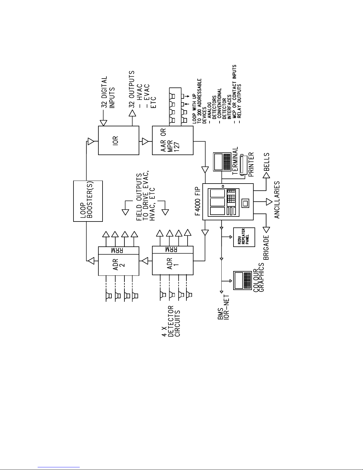
Figure 2.1 shows a block diagram of the F4000 System.
The F4000 Fire Alarm System consists of the following main components:
(a) A Fire Indicator Panel (FIP) containing an LCD Display and
(b) A number of "Responders" located around a Communications Loop. These
Responders, selected from a range of different types, provide the interface between
the various detection devices and the F4000 system.
(c) A number of optional Remote Zone Display Units (RZDUs) which mimic the FIP zone
displays at locations remote from the FIP.
2.1.2 F4000 FIRE INDICATOR PANEL (FIP)
The F4000 FIP is the heart of the F4000 system. It is microprocessor based and is the
MASTER display, operator control and Brigade Interface unit of the system.
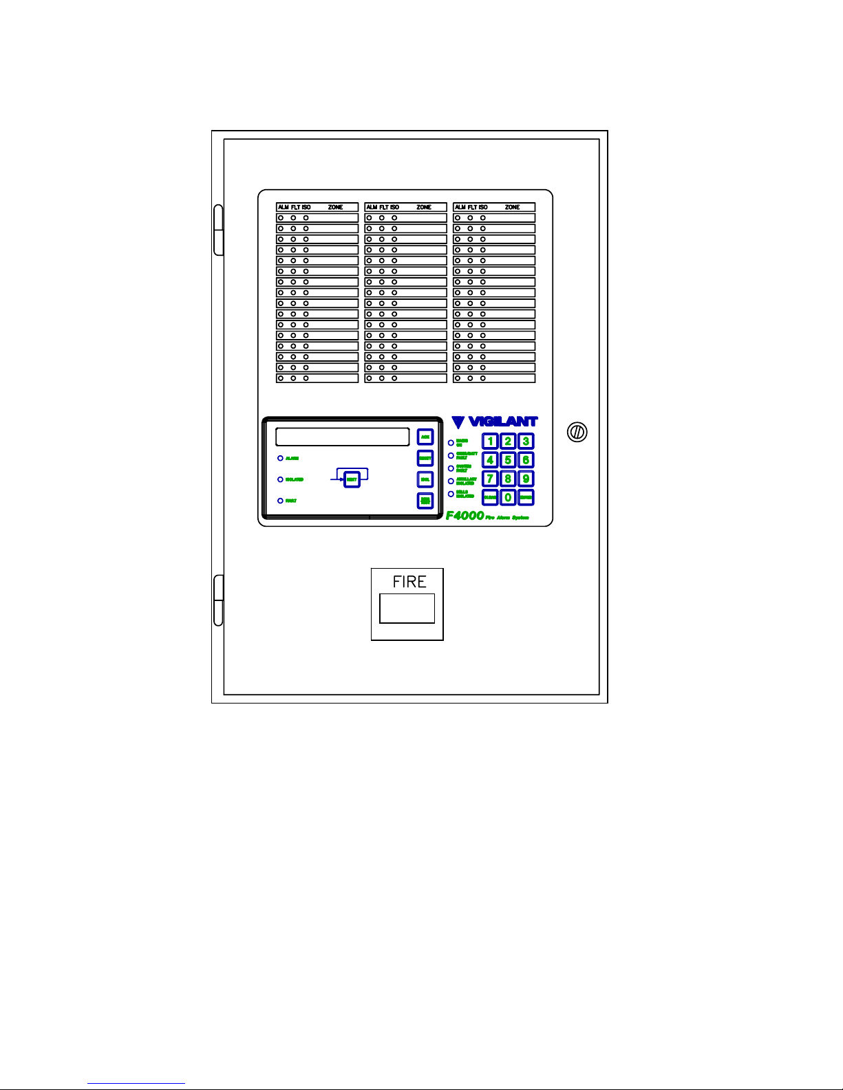
A front panel view of the F4000 LCD FIP is shown in Figure 2.2. This shows a standard
panel for up to 48 zones minimum. A 19" RAC cabinet version allows for 64 zones
minimum.
Specifically its functions are:
(a) To constantly communicate with all Responders via the communications loop, to
retrieve data from them, to transmit commands to them, and to monitor their integrity
at all times.
(b) To process the data obtained from the Responders and to generate displays and
annunciations as specified by AS1603.4, AS4050(INT), NZS4512 and any additional
requests as entered by the operator. This includes:
i) Up-dating the zone status LEDs to shown the ALARM, FAULT and
ISOLATED conditions.
ii) Controlling the relays that signal the Brigade.
Page 19
Document No: LT0117 F4000 LCD Operator's Manual
System Description
Issue 2.38 19 April 2002 Page 2-3
Figure 2.1
F4000 System Block Diagram
Page 20
F4000 LCD Operator's Manual Document No: LT0117
System Description
Page 2-4 19 April 2002 Issue 2.38
Figure 2.2
F4000 LCD Fire Indicator Panel
Page 21

Document No: LT0117 F4000 LCD Operator's Manual
System Description
Issue 2.38 19 April 2002 Page 2-5
F4000 FIRE INDICATOR PANEL (FIP) (CONTINUED)
iii) Controlling the relays used to drive auxiliary system devices such as bells,
door holders etc.
iv) Controlling remote plant by sending control data via the communications loop
to Responders fitted with output devices.
(c) To provide a simplified operator/Brigade interface that allows personnel to easily
control the day to day operation of the panel (eg: to acknowledge alarms, test zones,
isolate zones, etc).
(d) To monitor its own integrity and annunciate internal fault conditions.
(e) To provide a means of entering or modifying configuration data or "SYSTEM
DATABASE" from a Programming Terminal. This defines what the specific F4000
system consists of and how it should respond to inputs and control outputs.
2.1.3 RESPONDERS
The Responders are located around the protected premises and provide the interface
between the detection devices and the F4000 System. They are low power devices, deriving
their power from the 4 core communications loop that runs from the FIP, through each
Responder, and back to the FIP again. The F4000 System can monitor and control a
maximum of 127 Responders.
It is this loop system that makes the F4000 System so adaptable since larger systems are
implemented simply by extending the loop and adding more Responders in the appropriate
places.
To the "Operator" and "Fire Brigade", the Responders are "transparent" in that they simply
serve as data concentration points and have no operator features themselves.
2.1.3.1 ADVANCED DETECTOR RESPONDER (ADR)
The ADR is the standard alarm zone circuit processing unit of the F4000 system. ADRs are
therefore usually located near the zone circuit(s) they monitor. Up to four (4) Alarm Zone
Circuits may be connected to each ADR to monitor the approved compatible actuating
devices wired on the circuit.
The ADR may be upgraded to an "Advanced Relay (Detector) Responder" (ARR), with the
addition of a plug-in Responder Relay Module (RRM). This adds four (4) relay outputs to the
inputs provided on each ADR. Each relay can be programmed to operate on specific input
conditions. Alternatively the relay may be configured to belong to an ANCILLARY
CONTROL ZONE, so that operated, isolated and fault indications may be shown at the
F4000 FIP.
2.1.3.2 ANALOGUE ADDRESSABLE RESPONDER (AAR)
The Analogue Addressable Responder (AAR) allows up to 200 analogue addressable
devices to be connected on a loop of its own. These devices may be analogue addressable
smoke detectors or addressable device units (ADU) that provide specific input and output
facilities. The addressable devices may be mapped to zones in the same way that ADR
circuits are.
Page 22

F4000 LCD Operator's Manual Document No: LT0117
System Description
Page 2-6 19 April 2002 Issue 2.38
2.1.3.3 INPUT OUTPUT RESPONDER (IOR)
The Input/Output Responder (IOR) provides up to 32 digital inputs and up to 32 digital (or
relay) outputs, depending on its setup and the termination boards attached to it. To the FIP,
the IOR appears to be up to 8 ADRs (or ARR). The IOR is ideal for when a large number of
switched inputs or outputs are required at the same location.
2.1.3.4 MULTI-PROTOCOL RESPONDER (MPR)
The Multi-Protocol Responder (MPR) allows up to 200 analogue addressable devices to be
connected on a loop of its own. These devices may be analogue addressable smoke
detectors, addressable thermal detectors, addressable device units (ADU) that provide
specific input and output facilities, or addressable monitor and control modules. The
addressable devices may be mapped to zones in the same way that ADR circuits are.
MPRs with V1.01 or earlier software are limited to devices using the EWD protocol, ie Nittan
analogue addressable smoke detectors, ADUx I/O devices and the Z54A addressable base.
The operation of these MPRs is similar to the AAR.
MPRs with V2.00 or later software are able to communicate with one of two device families,
i.e.
(a) EWD Devices,ie Nittan analogue addressable smoke detectors, ADUx I/O devices
and the Z54A addressable base; or
(b) "130 Series" Devices, ie smoke detectors, thermal detectors, monitor modules and
control modules.
EWD DEVICES "130 SERIES" DEVICES
C7xA Smoke C131A Smoke
P7xA Smoke P131A Smoke
ADU002 Input T131A (with Type A or B operation) Heat
ADU003A Output ADM130 Input
ADU004A Output ADM131 Input
ADU006 Conventional ADM133 Input
Z54A Heat Base ADC130 Output
The device family is programmable on a per MPR basis, and an F4000 system can support
"130 Series" MPRs on the same F4000 responder loop.
2.1.4 F4000 COMMUNICATION LOOP
The F4000 "COMMUNICATIONS LOOP" is a 4 core loop that runs from the FIP, through
each Responder, and back to the FIP again. The loop powers the responders, and allows
the FIP to receive the circuit status from the responders and control their outputs.
The 4 wires of the communications loop are:
(a) Responder Power - 24V DC
(b) 0 Volt Common
(c) Communications Path 1
(d) Communications Path 2
The loop structure is such that it provides a very high degree of immunity against fault
conditions. A short circuit between any two wires or an open circuit in any wire is detected
and isolated so that the FIP is still able to power and communicate with all Responders.
Page 23

Document No: LT0117 F4000 LCD Operator's Manual
System Description
Issue 2.38 19 April 2002 Page 2-7
2.1.5 REMOTE ZONE DISPLAY UNIT (RZDU)
The F4000 system may include up to eight (8) Remote Zone Display Units (RZDUs) that are
monitored by the FIP, to provide repeater indicator panels at strategic points in large
premises. (i.e. mimic the zone displays of the master FIP at other parts of the protected
building). A number of additional non-monitored RZDUs and IO-NET boards may also be
connected.
The RZDU may be LCD based like the FIP, or be LED only. With both types 'System' and
'Fire Brigade' functions are available via the keyboard.
Programming of the RZDU allows it to display only a selected range of the zones shown at
the FIP. This could allow, for example, an RZDU on each floor of the building to show only
those zones on that floor.
In combination with the FIP's ability to allow Brigade function keypresses from an RZDU to
act upon a selected range of zones, RZDUs can provide for flexible zone display and control
applications to be configured.
The RDU (an LCD-based RZDU) can also send Brigade Test, Bells Isolate/ De-Isolate, and
Ancillary Isolate/De-Isolate commands to the FIP.
Additionally it allows individual zone acknowledgement, reset and isolate commands via the
FFCIF, and zone reset, isolate, de-isolate and status recall from the standard menu system.
2.1.6 COLOUR GRAPHICS TERMINALS
The F4000 System supports the addition of colour graphics display and control terminals
(CG4000) on the RZDU communication bus.
These units can be programmed to show graphical displays on zone alarm or fault
conditions. The operator can use function keys or the optional touch screen to generate
Silence, Reset and Isolate commands to the FIP and thus have remote control of the
brigade functions. The CG4000 will run on an IBM AT or compatible computer.
2.1.7 LOGGING PRINTER
A serial printer may be connected to the F4000 Master FIP to provide a log of events and
operator actions. The FIP can be programmed to print any combination of the following
event types:
(i) Zone Events, e.g. Alarm, Fault;
(ii) Zone Commands, e.g. Reset, Isolate;
(iii) Circuit & Point Events, e.g. Alarm, Fault;
(iv) A 24 hour "System Running" event.
The printer will always print System Events, e.g. communications failures, battery faults, etc.
The printout includes the time and date, the cause of the event (e.g. Zone, Circuit, RZDU or
FIP), and the event type. Events and commands for zones that have had a text name
programmed also have the name printed. The FIP is able to store up to 200 events for
printing, being the first 200 events to occur.
As events are printed, more events are able to be put into the list. If events cannot be put
into the list because it is full, the FIP keeps count of those events it has had to discard.
Page 24

F4000 LCD Operator's Manual Document No: LT0117
System Description
Page 2-8 19 April 2002 Issue 2.38
LOGGING PRINTER (CONTINUED)
When the FIP is next able to put more events into the list, it prints out the number of events it
had to discard.
The FIP separately maintains an internal history of the 900 most recent events. This history
can be viewed on the LCD and via the programming terminal. It can also be printed out, and
used to reconstruct the printer log if the F4000 FIP had to discard printer events.
2.1.8 PROGRAMMING/DIAGNOSTIC TERMINAL
The F4000 FIP also provides for the connection of a "PROGRAMMING/ DIAGNOSTIC
TERMINAL", usually a personal computer, to configure the F4000 system and provide
service diagnostic functions.
This is a temporary system component, and is ONLY required by the installer during
commissioning, or service. In normal system operation this could be replaced by the logging
printer for recording events and operation of controls.
2.1.9 NETWORKING OF F4000 FIPS
The F4000 Network LCD is an enhancement of the F4000 LCD that allows it to
communicate with other Panel-link compatible network devices, e.g. other networked F4000
or F3200 fire panels, networked printers and Colour Graphic displays.
The networking feature allows for F4000 to share:
(i) Alarm information for display and control of alarms on the LCD. Alarms on one FIP
can be displayed at other FIPs and Colour Graphics displays. Alarms can be
acknowledged, reset and isolated from the FIPs and Colour Graphics displays.
(ii) Output Logic status, allowing status and controls generated by the Output Logic at
one FIP to be used by the Output Logic at another FIP, e.g. for extended AS1668
Fan Controls.
(iii) MAF Status, so that one FIP can be a common brigade interface point for a number
of FIPs elsewhere on site.
(iv) Event Information for status monitoring and network event printing on network
printers and Colour Graphics displays, e.g. Overviews.
(v) Bells controls for activating, isolating and silencing the bells on remote FIPs as a
result of alarms or operator controls on the local FIP.
(vi) Zone Circuit and Point Status for monitoring applications.
(vii) Control of F4000 LCD/keypads.
Networked F4000 FIPs allow an operator to send single zone and zone range reset, isolate
and de-isolate commands to other FIPs; to recall and search for zone status on other F4000
FIPs; and to alarm, fault, auto reset and operate test zones on other F4000 FIPs.
Page 25

Document No: LT0117 F4000 LCD Operator's Manual
System Description
Issue 2.38 19 April 2002 Page 2-9
NETWORKING OF F4000 FIPs (CONTINUED)
Networked F4000 FIPs allow an operator to send System commands to System, Battery and
Bells test other FIPs, and to isolate and de-isolate bells and ancillaries at other F4000 FIPs.
Network F4000 FIPs can receive commands sent by other devices on the network, eg.
Colour Graphics, for control and test purposes.
Networked F4000 FIPs transmit local events and status onto the network for use by network
printers and Colour Graphic systems to allow remote logging of events, eg. one or more
system-wide event printers.
Networked F4000 FIPs are in most respects identical to a stand-alone F4000 FIP, except for
the inclusion of a networking card and the addition of the panel number in zone and point
numbering schemes.
Note, however, that configuration of a network F4000 may result in the functionality of the
LCD being essentially the same as a non-networked F4000.
A programming terminal operator can connect to another F4000 over the network, and
control and view that F4000 via its LCD and keypad as if the operator was at that F4000.
2.1.10 PROTOCOL TRANSLATION MODULE (PTM)
The PTM is used with F4000 networks and performs two functions:
(i) Interfaces a printer to the network for logging of events from panels on the network.
(ii) Interfaces “XL Graphics” colour graphics systems to the network.
2.1.11 PANEL-LINK MODBUS BRIDGE (PMB)
The PMB is used with F4000/F3200 networks to provide an interface into the network for
other systems that can use the Modbus protocol.
The PMB is able to pass system, zone and point statuses and values to the Modbus system.
It can also be used to pass commands back to the FIPs.
The PMB is used to interface Vigilant's Overview colour graphics systems to the F4000
network.
** PLEASE NOTE **
If your building or occupancy requirements change, then the F4000 FIP may require
reprogramming, so please consult your installation or maintenance company.
Page 26

F4000 LCD Operator's Manual Document No: LT0117
System Description
Page 2-10 19 April 2002 Issue 2.38
2.2 LCD FIP DISPLAYS
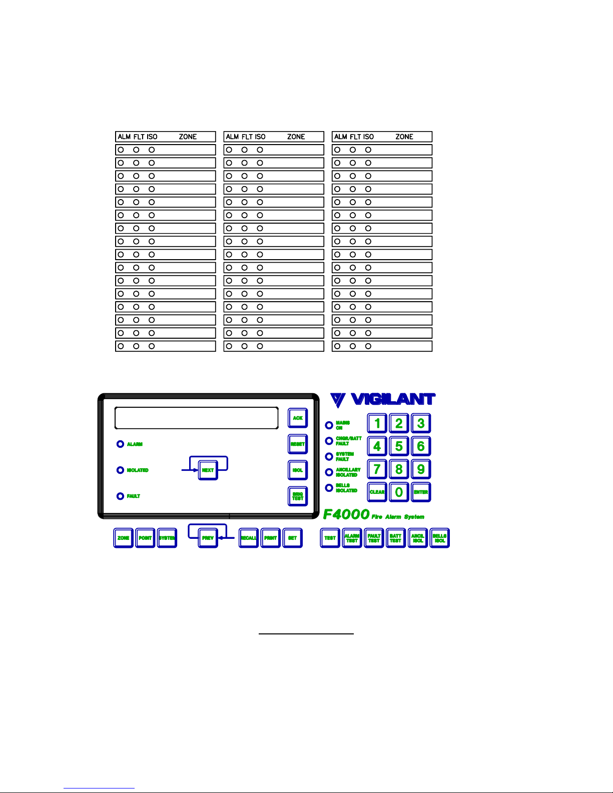
Figure 2.3 shows the front panel layout for an F4000 LCD FIP panel.
The F4000 FIP panel provides indications for:
(a) FFCIF Alarm, Fault and Isolate
(b) System Status
(c) Zone Status (optional)
There are 3 LEDs in the red-bordered FFCIF area that show common zone status:
(a) Alarm (b) Fault (c) Isolate
The SYSTEM STATUS INDICATORS are a column of 5 LEDs beside the numeric keypad,
that display the System Status information. The function of each LED is described alongside,
namely from top down:
(a) Mains ON (d) Ancillary Isolated
(b) CHGR/BATT Fault (e) Bells Isolated
(c) System Fault
In addition, New Zealand F4000 FIPs have an extra 3 SYSTEM STATUS indicators on the
display extender card:
(i) Normal (ii) Defect (iii) Fire
The optional ZONE STATUS INDICATORS display the status of each zone, whether an
Alarm Zone Circuit (AZC) or an Ancillary Control Zone (ACZ). Each zone has the following
three (3) indicators, and a space for installation dependent text, which is used to identify the
zone number and description.
(a) Red alarm "ALM" LED
(b) Amber fault "FLT" LED
(c) Amber isolated "ISO" LED.
An LED display card is fitted to show the zone status for each sixteen zones. The minimum
number of displays required at an F4000 LCD FIP panel is zero. However, 4 can be fitted in
the standard cabinet (FP0746) for displaying up to 64 zones. For New Zealand systems,
one of these positions will usually be taken up by the display extender board. Alternatively
the F4000 may be supplied in a rack cabinet configuration, which provides up to 64 zones in
each 7U module.
Page 27
Document No: LT0117 F4000 LCD Operator's Manual
System Description
Issue 2.38 19 April 2002 Page 2-11
FIGURE 2.3
F4000 FIP DISPLAY
Page 28

F4000 LCD Operator's Manual Document No: LT0117
System Description
Page 2-12 19 April 2002 Issue 2.38
LCD FIP DISPLAYS (CONTINUED)
The LED indicators may be either:
(a) Unlit (OFF); or
(b) Slow Flashing (SF), every 2 seconds; or
(c) Flashing (F), every half a second; or
(d) Rapid Flashing (RF), 10 times per second; or
(e) Steady (ON).
In normal operation all LEDs are OFF, with the exception of the green "MAINS ON" LED
indicator which is ON, and for New Zealand panels the "NORMAL" LED will be ON flashing.
An internal sounder (buzzer) is used to alert the operator to certain conditions.
A detailed description of all indications is contained in Chapter 4 "Interpreting the Display".
2.3 LCD KEYPAD INTRODUCTION
The FIP LCD keypad is shown in Figure 2.4 and is divided into two sections, namely:
(a) "Fire Fighter's Control & Indicating Facility" (FFCIF):
The area within the red border, containing 5 keys, 3 LEDs, and the LCD.
(b) All other keys and indicators used for zone resetting, isolating, testing and
information recall functions.
The two keyboard sections are not, however, entirely independent and some functions
require use of both keypad sections.
If a keypress is valid the sounder will give a short beep whenever a key is pressed.
A longer duration error beep will sound to draw attention to illegal key presses. The FIP LCD
may also display an error message. If this occurs, try the command or entry again.
For more details on specific operating instructions refer to Chapters 5, 6, 7, and 8, for
"Brigade", "System", "Zone" and "Point" functions respectively.
Page 29
Document No: LT0117 F4000 LCD Operator's Manual
System Description
Issue 2.38 19 April 2002 Page 2-13
FIGURE 2.4
F4000 FIP KEYPAD LAYOUT
2.3.1 AVAILABLE FUNCTIONS
The F4000 LCD FIP provides all of the isolate and test functions of the original F4000 FIP.
However, the new LCD and keypad allow for more features, such as status recalls, history
recalls and setting of time and date.
The available functions accessible via the LCD keypad are:
Zone Functions
Reset
Isolate
Alarm/Fault/ACZ Operate/Auto Reset Tests
Point Functions
Reset Device/History/Tracking
View & Set Sensitivity
Isolate
System Functions
Test System
Battery Test
Bells Isolate
LED/Display Test
Bells Test
Brigade Test
System Fault Reset
Global Reset
Global Isolate
Recalls
Zone Alarm Events
Zone Alarms/Faults/Isolates/Off-Normals/Pre-Alarms
Analogue Values
Analogue Levels
Point Status
Point % Dirty
System Faults
History
Page 30

F4000 LCD Operator's Manual Document No: LT0117
System Description
Page 2-14 19 April 2002 Issue 2.38
AVAILABLE FUNCTIONS (CONTINUED)
CRCs/Date Time Database Last Changed
Set Commands
Time & Date
Passwords
Most functions are selected by entering a command sequence on the keypad. This manual
explains the more basic sequences. Other sequences may exist, which are often the same
command sequence with the order of the keypresses altered, or special short cut
sequences.
Operators will discover these shortcuts primarily by using the keypad and gaining experience
of its capabilities.
2.3.2 ACCESSING A PARTICULAR FUNCTION
To access any particular function, the keypad and LCD provide a number of different paths.
Some functions are accessible by a single keypress.
For example, pressing the "RESET" key followed by the "ZONE" key and zone number, or
pressing the "ZONE" key followed by the zone number then the "RESET" key, will both
result in access to the zone reset function.
Often, the entry of a command sequence will require a number to be entered, e.g. a zone
number, or time and date.
2.3.3 MENU OPTION SELECTION
The menuing system on the LCD presents the options available by displaying an option
number e.g. 1, followed by the option, e.g. RESET. Selection of any option is possible by
two methods:
(a) Press the number key corresponding to the option required e.g. pressing the "1" key
for the "1:RESET" option will select "RESET".
(b) If the option has an equivalent key on the keypad, press that key, e.g. for the
example in (a), pressing the "RESET" key would also select the "RESET" option.
This may not be possible in some menus, to avoid ambiguities.
(c) If a "MORE" option is displayed, the "MORE" option can often be selected by
pressing the same key that was used to access the particular menu.
2.3.4 LCD KEYPAD NUMBER ENTRY
When entry of a number is requested, a cursor will be displayed. The standard entry keys
are the number keys, "0" to "9" and the "POINT" key.
To enter a number, press each number key as required. The LCD will display each digit as it
is entered. Pressing the "POINT" key displays a ".". This is used to separate numbers, e.g.
for zone ranges, or time and date entry.
If an error is made, pressing the "CLEAR" key will wipe any number entry made so far and
allow the correct number to be entered.
Page 31

Document No: LT0117 F4000 LCD Operator's Manual
System Description
Issue 2.38 19 April 2002 Page 2-15
LCD KEYPAD NUMBER ENTRY (CONTINUED)
If the "CLEAR" key is pressed when no number has been entered, the LCD keypad will "step
back" to the menu or display what was shown before the number was requested.
Pressing the "ENTER" key signals the LCD keypad that the number entry is complete, and
that the number should be checked for validity. If it is valid, the next stage in the menu is
displayed. Note that various shortcuts may also be permitted to end number entry and to
automatically select an option from the next menu. Refer Section 2.3.5.
2.3.5 COMMAND ENTRY SHORTCUT
To allow operators to perform functions quickly, the LCD keypad provides some shortcut
sequences. These allow faster access to functions by shortening the key entry sequences.
Some menus consist of 2 or more menu displays. The next set of options is displayed by
selecting the "MORE" option. In a number of cases, menu options in a subsequent display
can be selected by pressing the keypad key that equates to the selection in the subsequent
display (not the number key that would be used to select the option if that menu was
displayed).
As an example, the RECALL menu has two displays. The ZONE option is in the second
menu display.
To access the recall zone menu, an operator can either:
(i) Press the "RECALL" key to access the RECALL menu,
Press the "RECALL" or "4" key to access the second display (MORE option),
Press the "1" or the "ZONE" key to access the "ZONE RECALL" display,
or alternatively,
(ii) Press the "RECALL" key to access the RECALL menu,
Press the "ZONE" key to access the ZONE RECALL menu.
In general, the "ENTER" key is pressed to indicate that entry of a number is complete.
In some of cases, other keys may be pressed which have the same effect as the "ENTER"
key, but also provide a shortcut by automatically selecting an option from the next menu.
As an example, to Reset Zone 15, an operator may enter either of the following key
sequences.
(i) "ZONE", "1", "5", "ENTER", "RESET", or
(ii) "ZONE", "1", "5", "RESET".
The "NEXT" and "PREV" keys can be used in a number of menu options to change the
selection. For example, when the zone function menu is displayed ("RESET, ISOLATE,
RECALL, TEST, SET") a zone number is displayed along with the zone description.
Pressing the "NEXT" key will select the next numbered zone, pressing the "PREV" key will
select the previous numbered zone. Any subsequent menu option entered will act upon the
newly selected zone.
In some cases, the "NEXT" and "PREV" keys may not be valid, if stepping to the next or
previous device would result in an invalid selection, e.g. zone testing an ACZ.
The Point number entry prompt has a special entry shortcut. If no point number has been
entered when the "Enter" key, or any other valid shortcut key, is pressed the F4000
automatically selects the first configured point, if any.
Page 32

F4000 LCD Operator's Manual Document No: LT0117
System Description
Page 2-16 19 April 2002 Issue 2.38
2.3.6 THE "CLEAR" KEY & THE ABORT SEQUENCE
The "CLEAR" key, when pressed once, is used to step backwards through the previously
entered command sequence.
2.3.7 THE "BRIG TEST" KEY
The Brigade test key, "BRIG TEST", can be pressed at any time, regardless of any
command sequence being entered.
The "BRIG TEST" key, when pressed and held for 2 seconds, signals an alarm to the
brigade, plus the FFCIF alarm LED is turned ON.
The brigade alarm condition is active for as long as the "BRIG TEST" key is held down.
When it is released, the brigade test condition is removed, and if there is no MAF alarm the
brigade alarm relay and FFCIF alarm LED will return to their inactive states.
Note that in some cases, activation of the brigade test function may be programmed to be
disabled, although activation of ancillary functions controlled by the BGT token will still occur
if the key is pressed and held.
2.3.8 LCD INFORMATION DISPLAYS
When the LCD is not displaying the alarm list or being used for entry of a command
sequence, it shows one of the following information displays:
(a) Base Display - in general, this shows the system name and current time and date. In
addition, another field indicates the software version, whether the FIP has processing
enabled, is Automatic testing, or Powering up. If off-normal conditions exist, totals of
the off-normal states, or a fault action text, are displayed.
The actual display shown depends upon the current state of the FIP.
A special form of the base display is active whenever the Fault Sounder is operated.
In this case, the LCD indicates that a fault is present, and displays a fault action text
that will have been configured by the installer of the system.
Pressing any key will stop the fault sounder, which also clears the message from the
display. An operator can then ascertain the source of the fault using the LCD keypad
(eg offnormal counts, fault recalls) and the status LEDs.
(b) Zone Recall Display - shows zone status for a particular zone. The "NEXT" and
"PREV" keys can be used to select a different zone. The "next" and "previous" zone
displayed is dependant upon the selected recall, e.g. all zones, only those zones in
alarm, only those zones that are isolated, etc.
(c) Point Recall Display - shows either point status (alarm, fault, etc), analogue values
(current and tracked values, history), analogue levels (current levels and
sensitivities), or detector % dirty information.
F4000 V2.35 treats ADR circuits and relays as points, thus their status can be
recalled and searched.
Page 33

Document No: LT0117 F4000 LCD Operator's Manual
System Description
Issue 2.38 19 April 2002 Page 2-17
LCD INFORMATION DISPLAYS (CONTINUED)
The "NEXT" and "PREV" keys display the information for the next or previous point.
The selection of the point depends upon the mode of the recall, either all points, or
searches for point status meeting certain criteria e.g. points in dirty alert.
(d) History Recall Display - displays the stored event history. Newer and older events
are displayed by pressing the "NEXT" and "PREV" key respectively.
Pressing the "CLEAR" key whilst in the Zone Recall, Point Recall or History Recall displays
will make the system revert to the Base Display. All command sequences can be started
from any of the displays. Note, however, that how some command sequences proceed is
dependent upon which display was being shown. Refer Section 2.3.9 Starting Command
Sequences from Different Information Displays.
2.3.9 STARTING COMMAND SEQUENCES FROM DIFFERENT INFORMATION
DISPLAYS
The LCD keypad is usually in one of three modes:
(i) Alarm List display, or "FFCIF", when alarms exist in the fire alarm system.
(ii) Command Sequence Entry, when commands are being entered.
(iii) Information Display mode, when zone status, point status, time and date or history
recalls are being shown.
Often, the pressing of a key to start a command sequence will have a different effect,
depending upon what mode the LCD was in.
As an example, pressing the "ZONE" key whilst the time and date are being displayed, will
result in a prompt for a zone number. If zone information was being displayed, however, the
LCD keypad would assume that the zone being viewed is the zone to be selected, and no
zone number would be requested.
If the LCD makes an assumption that is not correct, pressing the "CLEAR" key will allow an
operator to recover to a position at which, for example, the required zone number can be
entered, or, an alternative command sequence entered.
As a example, if zone status is displayed, and an operator wishes to reset system faults,
then pressing the "SYSTEM" key, followed by the "RESET" key results in the required
function being executed. However, if the "RESET" key had been pressed first, the LCD
keypad would have queried whether the zone that was displayed should be reset. In the
event of this occurring, pressing the "CLEAR" key will make the LCD keypad revert to the
zone status display. The "SYSTEM RESET" command sequence can then be used to
execute the required function.
Alternately, the "Clear" key can be pressed until the base display is obtained.
Page 34

F4000 LCD Operator's Manual Document No: LT0117
System Description
Page 2-18 19 April 2002 Issue 2.38
2.4 AUDIBLE TONES
Any requirement for operator intervention is signalled by the sounding of the FIP's internal
buzzer. The buzzer can be activated in a number of different modes, each of which gives
some indication as to the type of event that has occurred. The internal sounder provides the
following audible tones in order of decreasing priority (see note below):
(a) ZONE / SYSTEM FAULT - Steady Tone
A continuous tone indicates that an un-isolated zone has gone into FAULT, or a system fault
has been detected. Note that the Zone Fault buzzer can be disabled by programming, and
for V2.31(N) or later FIPs the zone/system fault tone can be made to be of lower priority than
the zone alarm tone.
(b) KEYPAD "INPUT ERROR" - Long single beep
(c) KEYPAD "KEY ACCEPT" - Short single beep
(d) ZONE ALARM - Two Beeps per Second
A regular, two beeps per second tone, indicates that an un-isolated MAF mapped zone has
gone into ALARM. Note that the Zone Alarm buzzer can be programmed to be disabled, or
made the highest priority tone (V2.31(N) or later).
(e) TEST FAIL - Fast Pulsing Beeps
A 4 fast beeps then pause tone indicates that a zone, system, or power-up test has failed.
(f) PANEL FAULT / DOOR INTERLOCK - Slow Beeping
A long beep followed by a pause tone. This can indicate specific types of panel faults,
please call service. If the FIP is not able to process alarms, if certain tests are operating or
links are in incorrect positions, the buzzer will sound in this manner if the door is closed.
Pressing any keypad key will automatically silence the buzzer.
Page 35

Document No: LT0117 F4000 LCD Operator's Manual
System Description
Issue 2.38 19 April 2002 Page 2-19
2.5 NETWORKED PANELS
2.5.1 NETWORK FIP & NETWORK ZONE NUMBERING
When F4000 FIPs are networked together there must be a way to identify each FIP and the
zones on that FIP.
In this manual, reference is made to "local" and "remote" panels. A local panel is the panel
at which an operator is controlling the system from. Remote panels are all other panels on
the network. This applies even if a number of networked panels are co-located.
When a networked FIP is configured, it is programmed with a unique number between 1 and
254. This is its System Identification Number, or SID. The SID is used to:
(a) Identify a specific FIP.
(b) Identify a zone on a specific FIP, by combining the SID and Zone number as
detailed below.
For a networked F4000, zone numbers and zone ranges fall into 3 formats:
(i) Zone number(s) less than 1000 are local zones, ie. specific to the panel at which the
number is being entered or displayed, eg. Z57, Z135.189.
(ii) Zone number(s) greater than, or equal to, 1000 are network zones, eg. Z32105 or
Z17001.17095. The SID of the FIP that has the zone is the network zone number
divided by 1000. The actual zone number on that FIP is the remainder after dividing
by 1000. Eg. Z1057 is Zone 57 on FIP number 1.
Z35218 is Zone 218 on FIP number 35.
Note that all zeros must be entered, eg. for Zone 1 on Panel 2, the entry must be
2001, ie. the intermediatory 0's are necessary.
(iii) Zone numbers less than 1000 preceded by the SID of the FIP that has the zone(s).
Eg. (a) Z57:1 - Zone 1 on Panel 57.
(b) Z2:135.208 - Zones 135 to 208 on Panel 2.
(c) Z61..72 - Zone 72 on Panel 61.
(d) Z85..24.154 - Zones 24 to 154 on Panel 85.
The SID comes before the colon ":" or double points "..".
The zone numbers come after the colon or double points.
A colon is entered using the SYSTEM key. Double points are entered by pressing the
POINT or hidden key twice.
For F4000, zone numbers can be entered in any of the above formats. However, F4000 will
reject any zone range that extends across more than one FIP, eg. Z35097.36002 is illegal.
F4000 always displays network zones in format (ii).
If a zone number or range is entered in formats (i) or (ii), and the SID is that of the local
F4000, then the zone(s) may be converted back to format (i) for local processing.
When alarm events are sent from one FIP to another on the network, the zone number sent
is automatically pre-formatted into the network zone format (ii) for display on the LCD.
Page 36

F4000 LCD Operator's Manual Document No: LT0117
System Description
Page 2-20 19 April 2002 Issue 2.38
2.5.2 ZONE NUMBER ENTRY EXAMPLES
(i) Zone 27 on Local Panel.
(ii) Zone 27 on Panel 86.
OR
OR
(iii) Zones 5 to 16 on local panel.
(iv) Zones 5 to 16 on Panel 7.
Page 37

Document No: LT0117 F4000 LCD Operator's Manual
System Description
Issue 2.38 19 April 2002 Page 2-21
2.5.3 ZONE FUNCTION CHANGES
The zone functions at a networked F4000 are altered in the following ways:
(i) Network zone number and ranges entry is permitted, although not all functions can
be executed on Network Zones.
(ii) Reset, Isolate and De-Isolate commands can be issued to Network Zones and Zone
Ranges.
(iii) Zone tests can be issued to zones on other network FIPs.
(iv) The status of zones on other network FIPs can be recalled, and can be searched for,
across the network.
2.5.4 SYSTEM FUNCTION CHANGES
The system functions at a networked F4000 are altered in the following ways:
(i) When the SYSTEM key is pressed, a prompt is displayed allowing selection of either
the local system or a system elsewhere on the network.
(ii) The following functions can be initiated at a network F4000 by another network
F4000 panel.
- Ancillary Isolate/De-Isolate
- Battery Test
- Bells Isolate/De-Isolate/Test
- Bells Test
- System Test
-System Reset
(iii) A network F4000 may be programmed to act as a common brigade interface point for
a system, and/or display the off-normal totals for the whole network system.
(iv) A network F4000 may be programmed to allow control of its bells by other FIPs on
the network. Alarms or Trial Evacuation (NZ) on other FIPs may turn the local bells
ON. The bells may be silenced as a result of isolating the bells at another FIP or
activation of Silence Alarms at another FIP (NZ).
(v) A network F4000 can recall an overview of the system status of other FIPs on the
network.
(vi) A network F4000 may be programmed to have its internal sounder silencable as a
result of the actions of remote operators.
Page 38

F4000 LCD Operator's Manual Document No: LT0117
System Description
Page 2-22 19 April 2002 Issue 2.38
2.5.5 OPERATIONAL DIFFERENCES
For V2.3xN, operation of the LCD keypad is modified to take into account alarms in the
FFCIF list and the displayable totals that have come from other FIPs on the network.
In the following, alarms in the FFCIF list include local and any remote alarms, and the totals
are the combination of local and any remote totals.
(a) The Alarm LED will be on:
Flashing: Any unacknowledged alarm in the FFCIF list, or any unacknowledged
zone alarm on the local FIP.
Steady: If any alarms are in the FFCIF list, and all are acknowledged, or if the
alarms total on the base display is not zero, or if there is a zone in
alarm on the local FIP.
(b) The Fault LED will be on:
Steady: If the faults total on the base display is not zero, or if there is a zone in
fault on the local FIP.
(c) The Isolated LED will be on:
Steady: If the isolates total on the base display is not zero.
Flashing: If any point on the local FIP is isolated or a point on a network FIP is
isolated and the F4000 is combining MAF status.
(d) The FIP buzzer turns on:
Steady: Upon a local fault or system fault, or the occurrence of a fault on a
networked FIP whose SID is programmed into the SID list of this FIP
and the local FIP is programmed to display network totals. At the
base display, the Fault Action Text will also be displayed.
Pulsing: Upon a new alarm (local or network) being put into the FFCIF list, or a
new MAF alarm on the local FIP.
Rapid Pulsing:Upon a local test failure, eg. system test.
The FIP buzzer is cancelled:
- Whenever a key is pressed on the FIP keypad.
- For Alarms when there are no more alarms in the FFCIF list or unisolated alarms
on the local FIP.
- For Faults when there are no more unisolated faults on the local FIP, or on any
networked FIPs which can turn the fault buzzer on at the local FIP
- Upon reception of remote System Fault Reset, FFCIF commands or any
commands, if enabled by programming. (Refer 3.10).
Page 39

Document No: LT0117 F4000 LCD Operator's Manual
System Description
Issue 2.38 19 April 2002 Page 2-23
OPERATIONAL DIFFERENCES (CONTINUED)
A number of keypad functions that take time to complete, eg. zone isolate/de-isolate and
zone searches, have a simple flashing asterisk that indicates that the function is still
operating.
A significant point to note is that the networking of FIPs introduces delays when showing
data and responding to commands. These delays did not exist where there was only a
single FIP to be controlled, because the information was immediately onhand. With
networks, this is not the case, and delays arise due to the time taken to access the
information.
Consequently, allowance must be made for these delays when operating a networked FIP.
The effect of these delays are noted below, and in the following sections for the affected
keypad commands.
There may be a noticeable delay at times when a network F4000 attempts to retrieve text
and status from another network panel. If there will be a delay, F4000 will display a minimal
description on the LCD, eg. Z1057 or Network Panel 75. The actual status will be shown
when the true zone name text (if programmed at the remote FIP) is displayed.
Operators of networked FIPs must be aware that they should wait until the FIP has retrieved
the information before issuing any command, partly to ensure that the command they send
will not have an adverse effect, i.e. deisolating a zone in alarm, and also because operators
on other FIPs or colour graphics displays may also be trying to control the same zone.
Confusion can also arise due to the delay if a zone has just been isolated: the FIP may
briefly indicate that the zone is not isolated. However, after at most a few seconds, the
display will be updated to show the correctly isolated status.
Network F4000 FIPs can combine the MAF status from other FIPs on the network. This
combined status is then used to drive brigade relays, etc.
F4000 V2.3xN has special handling for a Standby condition received from another FIP.
Remote Standby conditions do NOT result in the local FIP's Standby relay de-asserting
itself, rather, the remote Standby condition is treated as a System Fault, i.e. the fault relay
activates, the System Fault LED turns on, and the fault buzzer may sound. Standby and
System Fault from the other FIP can be viewed as separate items in the System Fault
Display.
Page 40

F4000 LCD Operator's Manual Document No: LT0117
System Description
Page 2-24 19 April 2002 Issue 2.38
2.5.6 NETWORK COMMAND TRANSFERS & RESPONSES
Whenever entry of a network command is completed, the F4000 attempts to send the
command to the correct panel on the network. It will then wait for a response from the
receiving panel.
The F4000 LCD display will show messages during this time to indicate what is happening.
"Network Command Sent" - the F4000 successfully stored the message for sending to the
other panel. The F4000 network driver will send the message across the network.
"Network Command NOT Sent" - the F4000 could not send the message because of high
network loading, or because the LCD display was still awaiting a response to its last request
for data.
"Network Command Accepted" - the receiving F4000 received the command and
processed it.
Note that even though a remote panel accepts the command, it may not action it. In this
case an exception message may be sent back to the originating panel - refer Section 2.5.7.
"Network Command NOT Accepted" - the receiving F4000 received the command but did
not process it. This may be due to a number of factors:
- The command was invalid because, for example, the zone number was invalid, or the
command issued could not be executed on the command subject, eg. trying to alarm
test an ACZ.
- The command could not be executed because: a similar but mutually exclusive
command was in progress (Reset); only one of the particular command could be
executed at the same time (Alarm Test); or the receiving F4000 was in a state which
means that the command could not be executed. (No processing).
"Network Command NOT Ackd" - the receiving F4000 should respond as soon as possible
with an Accepted or NOT Accepted response. If network loading is high, or the remote
F4000 is busy or is off line, a response may not be received within the programmed time. If
the time limit is exceeded, the local F4000 displays the above message. Note that
depending on the circumstances, the command may or may not have been received and
processed.
Page 41

Document No: LT0117 F4000 LCD Operator's Manual
System Description
Issue 2.38 19 April 2002 Page 2-25
2.5.7 NETWORK EXCEPTIONS
2.5.7.1 GENERAL
Network commands issued by one network FIP and sent to another may result in some
event, error or "exception" that it is desirable to display at the source of the command.
These exceptions may occur a significant period of time after the original command was sent
and accepted. An operator may need to remember what commands were sent to a
particular network FIP to be able to interpret the exception correctly.
As an example of an exception, a multi-zone de-isolation may leave some zones isolated,
because some zones have an active alarm or fault status.
A network panel is able to send special messages to the source of the command, indicating
the type of exception that has occurred. The receiver of the exception can then recognise
and display the data appropriately.
Exceptions have a level of priority assigned to them by the sender. An F4000 can be
programmed as to which priorities of exceptions get displayed, and which get ignored.
Consequently, some F4000s may only display more urgent exceptions, while others show
both the more urgent and less urgent exceptions.
2.5.7.2 DISPLAY OF EXCEPTIONS AT AN F4000 LCD FIP
When an exception is received by an F4000, the following occurs:
(i) If the FFCIF is not active:
(a) The LCD/keypad is interrupted from what it is displaying (although any
background display processing still operates, eg. zone or point status
searches).
(b) The LCD displays the SID number of the panel that sent the exception and a
"Press any key" prompt on the first line, and the exception message received
on the second line.
(c) Pressing any key will clear the exception display and the LCD keypad will
revert to its original display.
(d) If the FFCIF becomes active while an exception display is being displayed,
the exception is automatically cleared.
(e) Any new exception received before the current exception is cleared will be
ignored.
(ii) If the FFCIF is active, the received exception is discarded, so as not to disturb the
alarm information displayed.
Page 42

F4000 LCD Operator's Manual Document No: LT0117
System Description
Page 2-26 19 April 2002 Issue 2.38
2.5.7.3 F4000 EXCEPTION EXAMPLES
Network F4000s are able to generate the following exception messages:
"Not All Zones De-Isolated"
The zone range de-isolation command processed did not de-isolate one or more
zones because they were in alarm or fault.
"Zxxxxx Test Passed"
"Zxxxxx Test Failed"
"Zxxxxx Test Aborted"
"Zxxxxx Test Time Out"
The previous Zone test command issued to zone xxxxx had the noted result.
"System Test Passed"
"System Test Failed"
"System Test Aborted"
The previous System test command had the noted result.
"Battery Test Passed"
"Battery Test Failed"
"Battery Test Aborted"
The previous Battery test command had the noted result
2.5.8 NETWORK F4000 LCD DISPLAYS
A network F4000 may be programmed to display either its own off-normal totals or a
combination of its own totals and the off-normal totals of other devices on the network.
Consequently, some totals may exceed the maximum totals expected for a single F4000
panel.
If there are no off-normals, the "base" display of the F4000 LCD displays the system name,
date and time, and F4000 software version. The software version text can be replaced by
text that indicates the operational state of the F4000, eg. testing, no processing, etc.
The number of texts that can be shown has been increased to handle the cases where tests
have been started by operators at other panels on the network. The texts are:
"F4000 V2.3xN" V2.3xN Default text.
"AUTOMATIC TESTING" An automatic daily test is running.
"SYSTEM TESTING" A remotely initiated system test is running.
"BATTERY TESTING" A remotely initiated battery test or NZ 1 hour battery test is
running.
"ACZ TESTING" A remotely initiated ACZ test is running.
"ZONE TESTING" A remotely initiated Zone test is running.
The Fault Action text will still override the above texts if the fault buzzer turns on.
Page 43

Document No: LT0117 F4000 LCD Operator's Manual
System Description
Issue 2.38 19 April 2002 Page 2-27
2.5.9 NETWORK FAULT FINDING
When any network fault exists, F4000 annunciates a System Fault, signals fault to the
brigade and turns on the System Fault LED. An operator who uses the System Fault Recall
facility will then see in addition to any other faults "NetFlt" on Page 4 of the recall. The
Network Panel System Fault pages will show which panels also have Network faults and/or
are scan failed.
There are a number of faults that will turn on NetFlt and each generates a history/printer
event as per Section 6.8.3 Printer/History events.
To discover the cause of the network fault, recall the history via the LCD keypad or a laptop,
or review any event printouts. Network events have a time/date followed by "SID nnn",
where nnn is the SID of the remote panel that caused the event and will usually be between
1 and 254. A SID of 0 will most likely occur for the NET MSG DISCARDED event and
indicates that a broadcast message, i.e. a message that it is intended all panels receive, has
been discarded.
Most network faults are non-latching.
All network faults can be cleared by a System Fault Reset command. If the fault still exists,
then it will be re-annunciated.
2.5.10 NETWORK BELLS CONTROL
A V2.3xN F4000 can be configured to allow network bells control. The new functionality is
primarily of use by networks in New Zealand, but some features can be used by Australian
systems to achieve network-wide bells control.
Network Bells control consists of 2 functions:
(i) Turning the bells ON, for alarms and Trial Evacuation (NZ).
(ii) Silencing the bells on Network FIPs due to a Silence Alarms Activation (NZ) or
optionally by having the Bells Isolated at one or more FIPs on the Network.
If the local F4000 has Network Bells Control enabled, an unisolated MAF alarm at another
FIP on the Network will cause the local bells to turn ON, so long as the local bells are not
silenced or isolated.
If the local F4000 has Network Bells Control enabled, Trial Evacuation (NZ) at another FIP
on the Network will ALWAYS turn the local bells ON.
If the local F4000 has Network Bells Control enabled, reception of a Silence Alarms from
another FIP will always turns the bells OFF, unless they are ON because of a Trial
Evacuation.
In New Zealand, Silence Alarms is usually generated by operation of a switch.
For Australian and New Zealand operation, an F4000 can be configured to also send
Silence Alarms whenever the Local Bells are Isolated. Consequently, isolating the bells at
one FIP can silence all bells on the network.
Page 44

F4000 LCD Operator's Manual Document No: LT0117
System Description
Page 2-28 19 April 2002 Issue 2.38
NETWORK BELLS CONTROL (CONTINUED)
The Bells Isolate LED now has 4 distinct cadences which identify whether the bells can ring,
and, if not, how the bells have been silenced:
OFF - Bells will ring on alarm.
ON - Bells have been locally isolated.
SLOW FLASHING - Bells have been silenced remotely, i.e. RZDU or another
Network F4000.
2Hz FLASHING - Bells have been locally silenced.
If the local F4000 is configured to send Silence Alarms whenever its bells are isolated, and
other F4000s are configured for Network Bells Control, then isolating the local bells will
cause the local Bells Isolate LED to be ON steady, whereas the Bells Isolate LEDs on the
other F4000s will be slow flashing, indicating they are remotely silenced.
If more than one F4000 has its bells isolated or silenced, then ALL F4000 Bells Isolate LEDs
will be slow flashing. In this situation, it will be necessary to find all FIPs with Isolated Bells
or local Silence Alarms using the LCD keypad System Fault Recall.
When another F4000 is found to have its bells isolated, they can be de-isolated using the
Network System Bells Isolate LCD/Keypad command. If an F4000 is found to have its local
Silence Alarms activated, then it is necessary to un-silence that F4000 by checking its own
Silence Alarms switch and the switches at any RDU connected to that F4000.
Once all local and remote Bell Isolations and Silence Alarms have been removed, the local
bells will be able to ring.
If a remote F4000 sending Trial Evacuation or Silence Alarms onto the network becomes
scan failed, each condition can be cleared at a local FIP by activating Silence Alarms or Trial
Evacuation, respectively, at the local FIP, or both conditions can be cleared by pressing
Bells Isolate at the local FIP.
Other network F4000s receiving the new Silence Alarms / Trial Evacuation activations will
clear these statuses from the scan failed F4000 in a similar manner, i.e. one F4000 can clear
the conditions from the scan failed FIP at other F4000s on the network.
Pressing the Local Bells Isolate key will cancel any Trial Evacuation and Silence Alarms on
the local F4000 that have been activated by a scan failed F4000. It will also cancel the Trial
Evacuation state at other FIPs if the Local Bells Isolate state is configured to send a Network
Silence Alarms state.
2.5.11 NETWORK SOUNDER CONTROL
All F4000 FIPs silence their internal sounders when a key on the keypad is pressed.
All F4000 V2.34N or earlier FIPs silence their local sounder if they receive a System Fault
Reset command from the network.
F4000 V2.35N may be additionally programmed to silence the sounder if an FFCIF
command is received, or a Network command is received. Alternatively, Local Sounder
Silencing due to any network command can be disabled.
Page 45

Document No: LT0117 F4000 LCD Operator's Manual
System Specifications
Issue 2.38 19 April 2002 Page 3-1
3 SYSTEM SPECIFICATIONS
Page 46

F4000 LCD Operator's Manual Document No: LT0117
System Specifications
Page 3-2 19 April 2002 Issue 2.38
3.1 SYSTEM CAPACITY
Input Circuits - Up to 508
Circuit Detector Load - 2.5mA for Active EOL (FP0472 ADR)
(MAX) - 4.0mA for Active EOL (FP0523 ADR)
- 4.0mA for Active EOL (FP0755 ADR-M)
- 120µA for Passive 39K EOL
Display Zones - Up to 528
Input to Zone Map - Freely Programmable
Control Outputs - Up to 508 plus Master Ancillary Relay
Maximum Responders - 127
Remote Display Units - Up to 8 (additional mimics allowed)
Maximum Zones per Unit - 64-192 in 19" cabinets (256 in Extender)
Other Inputs - Supervised MCP on cabinet (not large 19" cabinets)
FIP Relays - Master Alarm (MAF) (2 OFF), Fault, Standby,
Isolate, Bells, Ancillary
Relay Ratings - FIP: 2A at 30 VDC
RRM: 1A at 30 VDC
Serial Port - Programmer Terminal/Printer
Serial Port Protocol - XON/OFF 300,1200,9600 baud, 8 bits, no parity
Other Ports - RZDU, Spare and Network
Port Protection - All to AS1603.4 1987 Admt 1 & 2
Communications Loop - 4 Wire (24 VDC, 0 VDC, TX, RX)
- O/C and S/C Fault Tolerant
Alarm Response Time - 3.8 seconds MAX (127 Logical Responders)
History Log - 900 events
Printer Buffer - 170 events
Mimic Driver - ALARM LEDs
Page 47

Document No: LT0117 F4000 LCD Operator's Manual
System Specifications
Issue 2.38 19 April 2002 Page 3-3
3.2 PHYSICAL
3.2.1 FIP, EXTENDERS, RZDUS
Standard Cabinets
Cabinet Size - 750 mm(H) x 550 mm(W) x 210 mm(D) + 20 mm MCP
Cabinet Material - 1.2 mm Mild steel
Cabinet Finish - Baked Epoxy painted
Cabinet Colour - Cream Wrinkle BFF998 CW
Mounting - Wall mount (4 Holes)
Access - Outer door left hinged (L003 key locked)
- Inner door right hinged. (fastened)
Shipping Weight - 21 kg (not including batteries)
Cabinet Rating - IP51
19" RAC Cabinets
Cabinet Size - 18U - 885mm (H) x 575 mm(W) x 380 mm(D)
- 885mm (H) x 575 mm(W) x 205 mm(D)
- 21U – 1050mm (H) x 575mm (W) x 355mm(D)
- 28U - 1330mm (H) x 575 mm(W) x 380 mm(D)
- 1330mm (H) x 575 mm(W) x 205 mm(D)
- 40U - 1865mm (H) x 575 mm(W) x 380 mm(D)
- 1865mm (H) x 575 mm(W) x 205 mm(D)
Cabinet Material - 1.6 mm Mild steel
Cabinet Finish - Baked Epoxy painted
Cabinet Colour - Cream Wrinkle BFF998 CW
Mounting - Wall Mount 18U - 4 holes
21U - 4 holes
28U - 6 holes
40U - 8 holes
Access - Outer door left or right hinged (L003 key locked)
- Inner door right hinged (fastened)
Cabinet Rating - IP51
NOTE: Special cabinet sizes, material or IP ratings are also available.
Page 48

F4000 LCD Operator's Manual Document No: LT0117
System Specifications
Page 3-4 19 April 2002 Issue 2.38
3.2.2 RESPONDER UNITS - ADR, AAR, MPR
Size - 240 mm(H) x 180 mm(W) x 50 mm(D)
Material - 1.0 mm Mild steel
Finish - Galvanised
Mounting - Surface/Wall mount
Access - Cover by Screws
Shipping Weight - 1.5 kg (not including RRM) - ADR/AAR/MPR
IP Rating - IP51
3.2.3 RESPONDER UNITS - IOR
PCB Sizes - IOR 270mm x 180mm
16 Way Relay Board 470mm x 93mm
16 Way Termination Board 140mm x 93mm
32 Way Termination Board 270mm x 93mm
Weight - IOR 300gm
16 Way IOR Relay Board 260gm
16 way Termination Board 90gm
32 Way Termination Board 170gm
Gear Plate 2.6kg
3.2.4 REMOTE DISPLAY UNIT (RDU)
3.2.4.1 WALL MOUNTING RDU WITH MAF
Size 750mm (H) x 550mm (W) x 210mm (D)
* MCP is an additional 20mm.
Material 1.2mm and 1.6mm mild steel
Finish Powdercoat BFF-998-CW Cream Wrinkle
(Iron Phosphate pre-treat)
Shipping Weight 22kg
3.2.4.2 WALL MOUNTING LOW PROFILE RDU
Size 177mm (H) x 450mm (W) x 50mm (D)
Material 1.2mm mild steel
Finish Powdercoat PR12/816C Grey
(Iron Phosphate pre-treat)
Shipping Weight 3kg
Page 49

Document No: LT0117 F4000 LCD Operator's Manual
System Specifications
Issue 2.38 19 April 2002 Page 3-5
3.2.5 PROTOCOL TRANSLATION MODULE (PTM)
Size 450mm (W) x 280mm (D) x 85mm (H)
Material 1.2mm mild steel
Finish Cover: Powdercoat Cream Wrinkle BFF-998-CW
(Iron Phosphate pretreat)
Base: Zinc Plate, Blue Passivate
Shipping Weight 3kg
3.2.6 PANEL-LINK MODBUS BRIDGE (PMB)
Size 295mm (H) x 240mm (W) x 80mm (D)
Material 1.2mm mild steel
Finish Powdercoat Cream Wrinkle BFF-998-CW
(Iron Phosphate pretreat)
Shipping Weight 4kg
Page 50

F4000 LCD Operator's Manual Document No: LT0117
System Specifications
Page 3-6 19 April 2002 Issue 2.38
3.3 ELECTRICAL
Mains - 240 VAC +6% -10%, 50 Hz, 150W
Internal Battery - 24 VOLT, Sealed lead-acid.
- Up to 24 Ampere Hour
Internal Charger (+VB) - 27.3 VDC (nominal at 20 °C) Regulated
Non Battery Backed Supply - 27.9 VDC (nominal at 20 °C) (+VNB)
Temperature Compensation - -36mV per Degree C
Supervision - Charger High/Low & Battery Low/Fail
Battery Disconnect (V2.31 onwards)
Battery Test - 1.2 Amp load (standard)
Maximum Load - 2.5 Amps with FP0474 (up to 7.5A with slaves)
- 6.0 Amps with PSU2406F
- 12.0 Amps with PSU2412F
Operating Voltage - 21.1 to 28.2 VDC
Quiescent Panel Current - 160mA (FIP)
AC Secondary Fuse F1 - 5.0 Amp (FP0474)
+VB Fuse F2 - 1.6 Amp (FP0474)
Bell Fuse F3 - 1.6 Amp (FP0474)
+VNB Fuse F4 - 1.6 Amp (FP0474)
Operating Temperature - -5 °C to 45 °C
Humidity - 10% to 90% RH non-condensing
ADR
Zone Circuit Voltage - 20 VDC nominal
Circuit Alarm Current - 5 to 8.6mA (FP0472 ADR)
- 9.1 to 12.0mA (FP0523 ADR & FP0755 ADR-M)
Alarm LED Boost - 20 VDC at 40 ms pulse via 470 Ohm (FP0472)
IOR
Inputs - Clean contact, voltage-free, supervised.
Outputs - Open collector, pull-down, 100mA @ 30V.
Page 51

Document No: LT0117 F4000 LCD Operator's Manual
System Specifications
Issue 2.38 19 April 2002 Page 3-7
3.4 INDICATORS
Zone LEDs - Red: ALARM
(Optional) - Amber: FAULT, ISOLATE
System LEDs - Green: MAINS ON
- Red: MASTER ALARM
- Amber: SYSTEM FAULT, BELL ISOLATE,SYSTEM
TEST, ANCILLARY ISOLATE, CHARGER/
BATTERY FLT.
Sounder - Keypress, & key error
- Pulsing ALARM / Steady FAULT
- Slow Pulsing OFF-NORMAL condition with door closed.
Diagnostic LEDs - Watchdog
(Main Board / Amber) - Display Fault
- RZDU Fault
- Loop Fault
- Software Fault
Responders - Status LED
- MPR/AAR Analogue Loop Status LEDs
New Zealand Mode - Red : FIRE
Indicators - Amber : DEFECT
- Green : NORMAL
Page 52

F4000 LCD Operator's Manual Document No: LT0117
System Specifications
Page 3-8 19 April 2002 Issue 2.38
3.5 KEYPAD CONTROLS
Keypad Type - 30 key keypad plus 2 line by 40 character LCD
Zone Functions - Alarm and Fault Test
- Isolate
- Reset
- Auto-Reset Test Mode
- Recalls
Ancillary Functions - Test, Isolate, Reset
Point Functions - Reset History/Tracking
- Recalls
- Set sensitivity
- Isolate
System Functions - Battery Test, Lamp Test
- System Test (RZDU Test)
- System Fault Reset
- Bell Test, Bell Isolate (FIP only)
- System Fault/History Recalls
- Set time and date
- Set LCD password
Brigade Functions - Acknowledge alarms
- Reset acknowledged zones in alarm
- Isolate acknowledged zones in alarm
- Brigade Test
New Zealand Mode - Trial Evacuation
(External Keyswitches) - Silence Alarms
Page 53

Document No: LT0117 F4000 LCD Operator's Manual
Interpreting The Display
Issue 2.38 19 April 2002 Page 4-1
4 INTERPRETING THE DISPLAY
Page 54

F4000 LCD Operator's Manual Document No: LT0117
Interpreting The Display
Page 4-2 19 April 2002 Issue 2.38
4.1 RESPONDING TO ALARMS
WHEN ANY ZONE RED "ALM" LED INDICATOR, OR THE FFCIF ALARM LED
INDICATOR IS FLASHING, OR THE LCD IS DISPLAYING AN UNACKNOWLEDGED
ALARM, PERFORM THE FOLLOWING OPERATIONS:
STEP 1 DO NOT PRESS "ACK", "RESET" OR "ISOLATE" KEYS ON THE PANEL
until the Fire Brigade arrives. The "NEXT" key can be pressed to view the
next zone alarm in the list. If the "NEXT" key is pressed, the internal sounder
will silence.
STEP 2 INVESTIGATE THE ALARM (if possible by Fire Safety Crew), and implement
appropriate fire control and extinguishing measures.
The FIRE SEARCH AREA will be indicated by a red flashing "ALM" LED
indicator(s) adjacent to the location description of the alarm zone(s) or by the
zone text displayed on the LCD.
STEP 3 Evacuate the areas if necessary.
STEP 4 ADVISE THE FIRE CONTROL STATION of both fires and false alarms.
STEP 5 KEEP A MEMBER OF THE FIRE SAFETY CREW ON STANDBY to direct
fire fighters to the source(s) of alarm and inform them of measures already
taken.
STEP 6 RECORD ALL EVENTS IN THE LOG BOOK PROVIDED.
────────────────────────────────────────────────────────────────────
** PLEASE NOTE **
────────────────────────────────────────────────────────────────────
The above procedure should only be executed by a trained fire officer, and may need to be
modified in accordance with any special conditions applying to your F4000 FIP installation.
────────────────────────────────────────────────────────────────────
Page 55

Document No: LT0117 F4000 LCD Operator's Manual
Interpreting The Display
Issue 2.38 19 April 2002 Page 4-3
4.2 DEALING WITH FAULTS
4.2.1 WHAT IS A FAULT?
A fault is any situation which prevents the panel from correctly performing its functions.
Possible faults include defects in external wiring or power feed to the detectors, faulty
detectors, component failures, faulty charger and low battery voltage.
In normal operation the only lit LED indicator should be the green "MAINS ON". For New
Zealand mode F4000 panels the green "NORMAL" LED indicator should also be ON. If
other indicators are active, or the "NORMAL" LED is OFF or flashing, this should be reported
and promptly investigated.
4.2.2 RESPONDING TO FAULT SIGNALS
If a fault occurs, the fault sounder will operate (steady tone) unless it is configured to not turn
on. If a zone fault exists, the FFCIF "FAULT" LED will be ON. If a system fault exists, the
"SYSTEM FAULT" LED will be ON. If a Battery/Charger fault exists, the "CHGR/BATT
FAULT" LED will be ON or FLASHING.
If the LCD keypad is at the "base display", the fault action text programmed by the installer
will be displayed.
The "CLEAR" key or "ACK" key may be pressed in order to silence the panel's fault sounder
until a service technician arrives. When the sounder is silenced, any fault action text display
will be cleared also.
If a fault or other off-normal condition exists, the LCD will display the number of Alarms,
Faults, Isolates and Other off-normal conditions. Note that the totals take a few seconds to
adjust when the number of off-normal states increases or decreases.
To determine the source of the fault conditions, use the following keypad commands:
Zone Status Searches command for zone faults (refer Section 7.6.3)
Recall System Faults command (refer Section 6.6)
Recall History command (refer Section 6.8)
Point Status Searches command (refer Section 8.1.5)
Note that the Recall Zone Searches will show all zones that have faults, regardless of the
Isolate status of the zone. The Recall History command can help to determine the sequence
of fault conditions as the events are ordered chronologically.
Once the source of the fault has been determined, apply the basic trouble-shooting
guidelines described in Chapter 10, then call your maintenance company.
NOTES: (a) Subsequent faults on the system will operate the fault sounder again.
(b) RECORD ALL EVENTS IN THE LOG BOOK PROVIDED.
Page 56

F4000 LCD Operator's Manual Document No: LT0117
Interpreting The Display
Page 4-4 19 April 2002 Issue 2.38
4.3 SYSTEM INDICATORS
NOTE: In the following sections the following abbreviations are used to describe the LED
indications:
OFF = LED unlit.
SF = LED flashing slowly (every 2 seconds).
F = LED flashing (every half a second).
RF = LED flashing rapidly (10 times per second).
ON = LED on steady.
4.3.1 "ALARM" LED INDICATOR
A Red indicator interpreted as:
(a) OFF The normal state
(b) ON One or more zones are in alarm. This is regardless of whether the zone is
isolated or de-isolated. If the FFCIF is configured to be MAF alarms, only
MAF zones will cause the LED to turn on. If it is configured for All Alarms
then any zone in alarm will turn the LED on.
(c) F An unacknowledged alarm event is present in the FFCIF alarm list or an
unacknowledged MAF alarm exists that was not able to be displayed in the
FFCIF list. Zones in alarm will be shown automatically for Type 3 FFCIFs and
can be viewed in Type 2 FFCIFs by using the RECALL key.
4.3.2 "FAULT" LED INDICATOR
An Amber indicator interpreted as:
(a) OFF The normal state
(b) ON One or more zones are in fault (regardless of whether the zones are isolated
or unisolated). The faults total on the base display will be non-zero.
4.3.3 "ISOLATE" LED INDICATOR
An Amber indicator interpreted as:
(a) OFF The normal state
(b) ON One or more zones is isolated. The "ISOLATE" indicator is affected only by
those zones numbered less than or equal to the programmed value of the
Isolate Relay Maximum Zone. The isolates total on the base display will be
non-zero.
(c) F One or more analogue points are isolated.
Page 57

Document No: LT0117 F4000 LCD Operator's Manual
Interpreting The Display
Issue 2.38 19 April 2002 Page 4-5
4.3.4 "MAINS ON" LED INDICATOR
A Green indicator interpreted as:
(a) ON The normal condition indicating mains power is present
(b) OFF An abnormal condition indicating that the mains supply to the FIP has been
interrupted.
Possible reasons are:
i. The MAINS ON/OFF switch on the FIP Power Supply module is
turned OFF.
ii. Fuse F1 on 1901-2 Power Supply Printed Circuit board is blown.
iii. The overload protection device on the switchboard has tripped.
iv. FIP Power Supply fault.
4.3.5 "CHGR/BATT FAULT" INDICATOR
An Amber indicator that is interpreted as:
(a) OFF The normal condition, indicating that the FIP's standby battery supply and its
associated charger are both normal, if the mains supply is on.
(b) ON The charging circuitry is not working correctly or is wrongly set up. Note that
a mains failure is not deemed to be a fault of the charger itself and does not
cause the indicator to come on: OR
(c) F The battery is in a poor state of charge. This may be normal, for example
after extended operation of the system in a mains failure condition, or may be
abnormal, indicating a battery or charger fault: OR;
The battery is disconnected, for V2.31(N) onwards with disconnect monitoring
enabled: OR;
Failure of a New Zealand 1 hour battery test will result in this indicator
flashing for the remainder of the 1 hour test period: OR;
The previously requested BATTERY TEST has been performed and failed.
Note: A successful BATTERY TEST will return the indicator to its normal
OFF state.
After 1 minute maximum of the battery test failing, the indicator will
reflect the current state of the battery/charger, which will be Normal or
Fault.
(d) RF A manually initiated BATTERY TEST is in progress.
Page 58

F4000 LCD Operator's Manual Document No: LT0117
Interpreting The Display
Page 4-6 19 April 2002 Issue 2.38
4.3.6 "SYSTEM FAULT" LED INDICATOR
An Amber indicator that is interpreted as:
(a) OFF The normal condition, indicating that the system is fully operational.
(b) ON Indicates that a system fault (as opposed to a zone fault) has been detected.
The fault may either be detected spontaneously, or as a result of a manually
or automatically initiated SYSTEM TEST.
Carry out a System Fault Recall (refer Section 6.6) to determine if the fault is
local, or at a remote panel on a network. If the fault is on a remote panel it
may be necessary to carry out a System Fault Recall at that panel to
determine the exact cause of the fault.
Note: More detailed diagnostics are only available via an event logging
printer or programming terminal, or by reviewing the history log using
the LCD keypad.
(c) SF The database is being downloaded to an Analogue Addressable Responder
(AAR) or Multi-Protocol Responder (MPR). Only when this is complete is the
system fully operational.
4.3.7 "BELLS ISOLATED" LED INDICATOR
An Amber indicator that is interpreted as:
(a) OFF Indicates that the alarm bells are currently enabled i.e. will sound in the event
of an alarm.
(b) ON Indicates that the alarm bells are currently locally isolated, i.e. will NOT sound
in the event of an alarm. Usually this is only used for test purposes.
(c) SF Indicates that the bells have been silenced due to the activation of the silence
alarms switch at an RZDU or another networked FIP (New Zealand mode), or
as a result of another networked FIP having its bells isolated (if this feature is
enabled).
(d) F Indicates that the bells have been silenced due to the activation of the local
external silence alarms switch at the FIP (New Zealand mode).
4.3.8 "ANCILLARY ISOLATED" LED INDICATOR
An Amber indicator that is interpreted as:
(a) OFF Indicates that ACZ 0 is enabled, and will operate the ancillary relay (if it is
controlled by ACZ 0) according to the programmed control strategy.
(b) ON Indicates that ACZ 0 is isolated, i.e. will NOT operate the ancillary relay (if it is
controlled by ACZ 0).3
Page 59

Document No: LT0117 F4000 LCD Operator's Manual
Interpreting The Display
Issue 2.38 19 April 2002 Page 4-7
4.3.9 "NORMAL" LED INDICATOR (NZ PANELS ONLY)
A Green indicator interpreted as:
(a) ON The normal state
(b) F The F4000 is Normal, but the mains supply is off.
(c) OFF An un-isolated alarm or fault condition exists. In this case the appropriate
FIRE or DEFECT indicator will be on flashing,
or
An abnormal condition exists, e.g. Processing Stopped, System Fault or
EEPROM Write Enabled.
4.3.10 "FIRE" LED INDICATOR (NZ PANELS ONLY)
A Red indicator interpreted as:
(a) OFF The normal state
(b) F One or more un-isolated MAF zones is in alarm
Master Alarm relay is activated, due to zone alarms or a Latched Battery Very
Low (NZ mode).
4.3.11 "DEFECT" LED INDICATOR (NZ PANELS ONLY)
An Amber indicator interpreted as:
(a) OFF The normal state
(b) F One or more un-isolated MAF zones is in Fault
A communications fault exists
The External Silence Alarms input is active at the FIP or an RZDU.
Battery low during test
Internal test failure
Processing has been disabled
Page 60

F4000 LCD Operator's Manual Document No: LT0117
Interpreting The Display
Page 4-8 19 April 2002 Issue 2.38
4.4 ZONE INDICATORS
NOTE: In the following sections the following abbreviations are used to describe the
LED indications:
OFF = LED unlit.
SF = LED flashing slowly (every 2 seconds).
F = LED flashing (every half a second).
RF = LED flashing rapidly (10 times per second).
ON = LED on steady.
4.4.1 ZONE ALARM ("ALM") LED INDICATOR
A RED indicator per zone that is interpreted as:
(a) OFF For Alarm Zone; The normal, non-alarm state
For Ancillary Zone; The normal, non operated state.
(b) ON For Alarm Zone; Indicates the alarm condition has been acknowledged and if
the zone is non-latching that the alarm condition still exists.
For Ancillary Zone; Indicates that the Ancillary Control Zone has been
activated.
(c) F For Alarm Zone; Indicates a new, yet to be acknowledged, alarm has
developed or failure of self test e.g. unexpected alarm in the zone.
4.4.2 ZONE FAULT ("FLT") LED INDICATOR
An Amber indicator per zone that is interpreted as:
(a) OFF The normal state.
(b) ON Indicates a FAULT condition has developed in that zone.
For Alarm Zone; A detector line fault
For Ancillary Zone; An Ancillary Supervision fault.
(c) F Encountered during a SYSTEM TEST, to indicate that the particular zone
failed its test sequence, or detected an unexpected alarm or fault.
NOTE: For New Zealand mode FIPs, zone defects (faults) are always non-latching,
but the LED indicators are always latching. Thus, if the defect condition goes
away, the zone status will be normal, but the defect indicator will remain ON
until the zone is RESET.
Page 61

Document No: LT0117 F4000 LCD Operator's Manual
Interpreting The Display
Issue 2.38 19 April 2002 Page 4-9
4.4.3 ZONE ISOLATED ("ISO") LED INDICATOR
An Amber indicator per zone that is interpreted as:
(a) OFF The normal state; indicates that the zone is not isolated and that any alarm or
fault conditions detected on that zone will generate Brigade signals, bell
operation, and ancillary device operation as configured for that zone.
(b) ON Indicates that the zone is isolated. Alarm and fault conditions will still be
displayed but will not initiate any control or annunciation functions.
(c) F Indicates that the zone is in "AUTO-RESET" mode.
4.5 LED PHASING
For FIPs with a large number of display boards, the power requirements can become
excessive if too many of the LEDs are on. To reduce the power requirements, the FIP is
able to "phase" the display boards.
The FIP calculates the number of LEDs on steady or flashing for all Display boards, but
excludes Relay Driver boards. If this number rises above 255, then phasing starts. If it then
falls below 249, phasing stops.
If phasing has started, then only 6 boards display their data at one time. All other LEDs on
Display boards are turned off. Every second, one board is turned off, and another is
enabled to turn on its LEDs. In this way, the 6 display board "window" is shifted around all of
the display boards. If phasing is not enabled, then all boards show their data.
TIME BOARD NUMBER
1
2
3
4
5
6
7
8
1
X
X
X
X
X
X
2
X
X
X
X
X
X
3
X
X
X
X
X
X
4
X
X
X
X
X
X
5
X
X
X
X
X
X
6
X
X
X
X
X
7
X
X
X
X
X
X
8
X
X
X
X
X
X
X = BOARD DISPLAYING DATA
FIG 4.1 PHASING OF DISPLAY BOARDS
Page 62

F4000 LCD Operator's Manual Document No: LT0117
Interpreting The Display
Page 4-10 19 April 2002 Issue 2.38
LED PHASING (CONTINUED)
At any time during phasing, a display board configured to be a Relay Driver board will never
be turned off. When it is the Relay Driver board's time to be turned off, it will continue to
display it's data.
TIME BOARD NUMBER
1
2
3
4
5
6
7
8
1
X
X
X
X
X
X
2
X
X
X
X
X
X
3
X
X
X
X
X
X
4
#
#
#
#
#
#
#
#
5
X
X
X
X
X
X
6
X
X
X
X
X
X
7
X
X
X
X
X
X
8
X
X
X
X
X
X
X = BOARD DISPLAYING DATA
# = RELAY DRIVER ALWAYS DISPLAYING DATA
FIG 4.2 PHASING OF DISPLAY BOARDS
4.6 CONTROL OF FIP BY MULTIPLE OPERATORS
For a standalone F4000 FIP, only one operator can have control over the FIP as there is
only one operator interface (the keyboard and LCD).
When an F4000 FIP is connected to:
- RZDUs
- RDUs
- Colour Graphics Displays
- Remote operator via the programming terminal, or
- Other panels via the Panel-Link network,
there may be more than one operator controlling the FIP. Ie. multiple operators could be
trying to reset, isolate, test, etc, the zones or other controllable items at the same time.
Depending on the system programming, alarms in the FFCIF alarm list may be
acknowledged, reset or isolated, from any of the operator interface points.
Thus alarms in the FFCIF list may disappear from the LCD because another operator has
reset the zones in alarm from, for example, a colour graphics system.
Also, the internal sounder may silence as a result of receiving and/or actioning a remote
operator’s command.
As of V2.35, the single keypad and LCD interface can be operated simultaneously by up to 3
users at a time:
• An operator physically at the FIP keypad/LCD.
• A remote operator connected via the programming terminal.
• A remote operator connected via the Panel-link network.
The physical LCD display will change in response to the actions of the remote operator.
Page 63

Document No: LT0117 F4000 LCD Operator's Manual
Operating Instructions - Brigade Functions
Issue 2.38 19 April 2002 Page 5-1
5 OPERATING INSTRUCTIONS - BRIGADE FUNCTIONS
Page 64

F4000 LCD Operator's Manual Document No: LT0117
Operating Instructions - Brigade Functions
Page 5-2 19 April 2002 Issue 2.38
5.1 INTRODUCTION TO BRIGADE FUNCTIONS
5.1.1 GENERAL OPERATION & DISPLAY
When an alarms occurs, the FIP takes over the keypad and LCD to display the alarm. The
keys that can be used are limited to those within the Fire Fighters Control and Indicating
Facility (FFCIF), the "PREV" key and the "CLEAR" key. The FFCIF is the area of the
keypad within the red border, as shown in Figure 5.1.
10:17:05 Thermal ALARM 1 of 1
Z 157 West Tower Floor 5 Plant Room
FIGURE 5.1
EXAMPLE FIRE FIGHTER'S CONTROL & INDICATING FACILITY ALARM DISPLAY
The FFCIF is programmed to operate in one of two modes:
(i) FFCIF Type 3 Mode - Each zone alarm is displayed on the LCD, and must be
individually acknowledged by pressing the ACK key when the alarm is displayed. All
acknowledged alarms can be reset or isolated by pressing the RESET and ISOLATE
keys respectively.
All alarms must be acknowledged before the FFCIF can be exited.
(ii) FFCIF Type 2 Mode - All zone alarms are silenced/acknowledged, reset and isolated
using common controls.
When an alarm occurs the LCD displays a screen indicating that alarms have
occurred and that they can be viewed by pressing RECALL.
From this screen all alarms can be silenced/acknowledged by pressing "ACK", reset
by pressing "RESET" or isolated by pressing "ISOLATE". If the alarms are recalled
then the FFCIF enters Type 3 Mode and the ISOLATE and RESET keys only operate
on individually acknowledged alarms. Pressing RECALL reverts the LCD display to
the Type 2 screen.
Page 65

Document No: LT0117 F4000 LCD Operator's Manual
Operating Instructions - Brigade Functions
Issue 2.38 19 April 2002 Page 5-3
GENERAL OPERATION & DISPLAY (CONTINUED)
Once all alarms have been acknowledged, and then reset or isolated, the FIP restores the
display and keypad to the exact state before the alarm occurred. Consequently, partly
entered commands or numbers can be finished, or any recalls that were being done are restarted.
5.1.2 FFCIF TYPE 3 OPERATION
When the FIP is displaying an alarm using an FFCIF in Type 3 Mode, the LCD displays the
following information:
(i) The time at which the alarm occurred, or a preview of the cause of the alarm
(programmable).
(ii) The zone alarm type.
(iii) Whether the alarm is acknowledged or not (Figure 5.1 shows an unacknowledged
alarm).
(iv) The total number of alarms and the sequence number of the currently displayed
alarm.
(v) The zone number and location. The location may be a zone name, a detector name,
or a combination of both.
The F4000 FIP maintains a list of alarms in the order in which they occurred. In the absence
of operator intervention, the LCD display will show the first alarm. All alarms in the list can
be viewed, one by one, by pressing the "NEXT" or "PREV" keys.
Each alarm can be individually acknowledged when it is displayed by pressing the "ACK"
key. The text "ACKD" appears on the display whenever an acknowledged alarm is viewed.
Once an alarm has been acknowledged, it can be removed from the alarms list by:
(i) Pressing the "RESET" key - all acknowledged alarms are RESET, and removed from
the list; or
(ii) Pressing the "ISOLATE" key - all acknowledged alarms are ISOLATED, and
removed from the list; or
(iii) The alarm condition being cleared from the detector on a non-latching zone.
Page 66

F4000 LCD Operator's Manual Document No: LT0117
Operating Instructions - Brigade Functions
Page 5-4 19 April 2002 Issue 2.38
5.1.3 FFCIF TYPE 2 OPERATION
When the FIP has been programmed for FFCIF Type 2 mode, the LCD displays a message
that indicates the global operations that can be performed. Pressing the ACK, RESET or
ISOL keys will silence, reset and isolate respectively, all un-isolated zones in alarm
(irrespective of their acknowledgement status).
The FIP still maintains a list of alarms as for FFCIF Type 3 operation, and these can be
viewed by pressing the RECALL key. The LCD then operates in FFCIF Type 3 mode, i.e. it
allows individual acknowledgement, reset or isolation of alarms. Pressing the RECALL key
allows an operator to return to the FFCIF Type 2 mode of operation.
REMINDER: In Type 2 operation, alarms do not have to be acknowledged before being
RESET or ISOLATED.
NOTE: In Type 2 operation, pressing the ACK key will silence the buzzer and mark
all events in the FFCIF list as "ACKD", however, the zones will NOT be
silenced, i.e. any Alarm LEDs for the zones will remain flashing.
5.2 SILENCING THE INTERNAL SOUNDER
5.2.1 FUNCTION
In FF mode (displaying an alarm) pressing any key in the FF area (except the Brigade Test
key) or the Prev key will silence the alarm or fault sounder. Thus to silence the buzzer in FF
mode it is safest to use the NEXT or PREV keys, and use the opposite key to step back to
the original alarm if there are multiple alarms present.
If the panel is not in FF mode then pressing any key will silence the alarm, fault, or test fail
sounder.
Note: The alarm bells are separately silenced by the Bells Isolate key.
5.2.2 OPERATING SEQUENCE
Press "CLEAR" key once.
- the internal sounder silences.
NOTE:
If a key sequence was being entered, it may be necessary to re-enter number information or
the last command, as the CLEAR key will, in addition to silencing the buzzer, either step
back through the menu or clear any number entry sequence that has started.
If all zone alarms are acknowledged, pressing the CLEAR key will result in the LCD exiting
FFCIF mode. It can be re-started by entering the Recall Alarm List command.
Any fault action text displayed as a result of the buzzer turning ON for a fault will be
automatically cleared by silencing the fault buzzer.
The sounder may also be silenced on receiving a remote operator command, depending on
the system programming and configuration.
Page 67

Document No: LT0117 F4000 LCD Operator's Manual
Operating Instructions - Brigade Functions
Issue 2.38 19 April 2002 Page 5-5
5.3 ACKNOWLEDGE ZONES IN ALARM
5.3.1 FUNCTION
In "FFCIF mode", pressing the "ACK" key performs the following functions:
(a) The displayed alarm is acknowledged.
(b) The pulsing alarm sounder is silenced.
5.3.2 OPERATING SEQUENCE
Press "ACK" key once:
- The flashing red "ALM" LED indicator for the zone goes steady
(ZONE ACKNOWLEDGED).
- Sounder (if any) will be silenced.
- LCD displays "ACKD" for the currently displayed alarm.
- If there are no more unacknowledged alarms in the system,
the ALARM LED goes steady.
NOTES:
(a) Subsequent non-isolated zone "ALARMS" or "FAULTS" on the system will re-operate
the indications, and sounder, as appropriate.
(b) Even if an unsilenced FAULT condition exists, the sounder will be silenced.
However, the FAULT LED will be ON, indicating the presence of a zone fault in the
system.
(c) If the LCD is in FFCIF Type 2 mode, zone alarms are NOT acknowledged and
silenced. The buzzer will silence and the alarm in the FFCIF list will be marked as
"ACKD". However, the Zone Alarm LED will remain flashing.
Page 68

F4000 LCD Operator's Manual Document No: LT0117
Operating Instructions - Brigade Functions
Page 5-6 19 April 2002 Issue 2.38
5.4 RESET ACKNOWLEDGED ZONES IN ALARM
5.4.1 FUNCTION
In "FFCIF mode", pressing the "RESET" key performs the following functions for all zones in
the alarm list that have been acknowledged:
(a) RESETS all circuits mapped to the acknowledged zone(s).
(b) Silences any alarm or fault sounder.
(c) Aborts Zone Test on any acknowledged zone under test.
(d) If no more un-isolated alarms exist, the bells will turn OFF, if they were ON.
(e) The acknowledged zone alarms are removed from the alarm list.
5.4.2 OPERATING SEQUENCE
Press "RESET" key once:
- LCD displays "Resetting acknowledged alarms".
- All acknowledged zones in the alarm list will be reset.
- All acknowledged (steady) red alarm indicators will be turned
OFF.
- Local Bells, if any, will be silenced if no more un-isolated zones
are in alarm.
- Sounder will be silenced.
NOTES:
(a) If the alarm condition on the zone circuits has not been removed, then the zone
alarm indicators and Local Bells will be re-activated (if not isolated), and a new zone
alarm will be put into the alarm list.
(b) Pressing "RESET" in the "FFCIF mode" does not affect Zone or Ancillary Zone fault
indications. Refer to the "Zone / Ancillary Reset" section in Chapter 7; "Operating
Instructions - Zone Functions".
(c) Pressing "RESET" in the "FFCIF mode" has no affect on isolated zones or zones in
"AUTO-RESET" mode, as they are unlikely to be in the alarm list.
(d) If a reset command is already in progress, the LCD will display "Cannot reset alarms
at this time". Wait until the original reset has completed and try again.
(e) If the LCD is in FFCIF Type 2 Mode, all alarms will be automatically acknowledged
and then reset, i.e. it is not necessary that the zone(s) be previously acknowledged.
Page 69

Document No: LT0117 F4000 LCD Operator's Manual
Operating Instructions - Brigade Functions
Issue 2.38 19 April 2002 Page 5-7
5.5 ISOLATE ACKNOWLEDGED ZONES IN ALARM
5.5.1 FUNCTION
In "FFCIF mode", pressing the "ISOLATE" key performs the following functions for all zones
in the alarm list that have been acknowledged:
(a) ISOLATES all acknowledged zones in the alarm list.
(b) Silences any Internal sounder condition.
(c) If all zone alarms are isolated, ie there are no unacknowledged alarms, then the
Local Bells will turn OFF.
(d) The acknowledged zone alarms are removed from the alarm list.
5.5.2 OPERATING SEQUENCE
Press "ISO" key once:
- The acknowledged zones in the alarm list will be isolated shown by the corresponding amber "ISO" LED indicator
turning ON.
- The Local bells (if any) will be silenced so long as all alarms
are isolated, ie there are no unacknowledged alarms.
- The Sounder will be silenced.
NOTES:
(a) Subsequent non-isolated zone ALARMS on the system will re-operate the alarm
indications, alarm sounder and local bells.
(b) Subsequent non-isolated zone FAULTS on the system will operate the fault
indication and steady fault sounder.
(c) To DE-ISOLATE alarm zones, FFCIF mode must be exited, and the zone selected
for de-isolation. Refer to the "Exiting FFCIF mode" section in this chapter, and the
"Zone Isolating / De-Isolating" section in Chapter 7 "Operating Instructions - Zone
Functions".
(d) If the LCD is in FFCIF Type 2 mode, all alarms will be automatically acknowledged
and then isolated, i.e. it is not necessary that the zone(s) be previously
acknowledged.
Page 70

F4000 LCD Operator's Manual Document No: LT0117
Operating Instructions - Brigade Functions
Page 5-8 19 April 2002 Issue 2.38
5.6 ISOLATING/DE-ISOLATING BELLS
5.6.1 FUNCTION
The isolate status of the bells can be changed at any time by pressing the "BELL ISO" key.
The status of the Bells isolation is shown on the "BELLS ISOLATED" LED as per Section
4.3.7. If the LED is on steady, slow flashing or 2Hz flashing, the bells will not sound. If the
LED is OFF the bells will sound when an un-isolated alarm is present.
Isolating the bells can serve as a method to silence the bells whilst un-isolated alarms still
exist.
De-isolating the bells allows the bells to turn on for subsequent alarms occurring, and can
serve to immediately turn the bells on again if any un-isolated zone alarm condition exists.
For New Zealand mode F4000 FIPs, the Bells Isolate LED flashes if a Silence Alarms
keyswitch has been turned on at the FIP, (2Hz flash), or at any RZDU or Networked FIP
(slow flash). Pressing the "BELLS ISO" key will change the isolate state stored within the
FIP, but the Bells Isolated LED will remain slow or 2Hz flashing until the Silence Alarms
keyswitch is turned off. At that time, the "BELLS ISOLATED" LED will turn OFF if the bells
are not isolated by the keypad, or ON if the bells are isolated by the keypad.
In Australian or New Zealand network systems, isolating the bells on the local FIP may result
in the bells on other FIPs being silenced, depending on how the system has been
configured.
5.6.2 OPERATING SEQUENCE
Press the "BELLS ISO" key once:
- If the bells were un-isolated:
- The BELLS ISOLATE LED turns ON.
- The bells, if ON, turn OFF.
- If the bells were isolated:
- The BELLS ISOLATE LED turns OFF.
- If any un-isolated alarm condition exists the bells turn ON.
NOTE:
If any subsequent alarm occurs, the bells will turn ON only if the bells are un-isolated, or for
New Zealand mode FIPs if the bells are un-isolated and are not silenced.
Page 71

Document No: LT0117 F4000 LCD Operator's Manual
Operating Instructions - Brigade Functions
Issue 2.38 19 April 2002 Page 5-9
5.7 DISPLAYING THE ALARM CAUSE
5.7.1 FUNCTION
In "FFCIF mode", the information for the zone in alarm is normally displayed. However, it
can be useful to know which circuit/point caused the alarm.
The LCD displays this information when the operator presses and holds the "POINT" key.
The time that the alarm occurred at and the alarm type are replaced by the circuit/point that
caused the alarm.
5.7.2 OPERATING SEQUENCE
To display the circuit/point that caused the alarm displayed, press and
hold the "POINT" key.
- The alarm time and type are replaced by the circuit/point that
caused the zone to go into alarm.
To restore the alarm display, release the "POINT" key.
- The alarm time and type are re-displayed.
NOTES: If the LCD is in FFCIF Type 2 mode, this keypress is invalid.
The FIP may be programmed to show a preview of the cause of the alarm on
the main alarm display instead of the alarm time. If this feature has been
enabled, when the "POINT" key is pressed the alarm time is displayed along
with the full alarm cause information.
F4000 V2.31 and later can be programmed to update the alarm cause text
whenever a new alarm cause is detected. They can also be programmed to
reannunciate a zone alarm when a new cause is received, i.e.
unacknowledge a previously acknowledged alarm, activate the alarm
sounder, and make the Master Alarm LED flash.
Page 72

F4000 LCD Operator's Manual Document No: LT0117
Operating Instructions - Brigade Functions
Page 5-10 19 April 2002 Issue 2.38
5.8 EXITING FFCIF MODE
5.8.1 FUNCTION
While in FFCIF mode, access to all other functions and displays is prevented. On occasion
it may be necessary to de-isolate a zone or perform some other function. To do so, FFCIF
mode must be exited.
FFCIF mode can be exited only when ALL alarms in the list have been
acknowledged/silenced.
When FFCIF mode is exited, the LCD reverts to the display it had before the alarms
occurred. At that stage, the required functions can be performed.
5.8.2 OPERATING SEQUENCE
Press the "CLEAR" key once:
- If all alarms are acknowledged, FFCIF mode is exited and the
LCD reverts to the display state that was showing before the
alarms occurred.
- If any alarms are NOT acknowledged, the sounder will produce
an error tone, and FFCIF mode will not be exited. It is
necessary to acknowledge all alarms before FFCIF mode can
be exited.
NOTE: To re-enter FFCIF mode to view the list of alarms, use the Recall Alarm List
command sequence. Refer 5.9 Recalling the Alarm List.
Page 73

Document No: LT0117 F4000 LCD Operator's Manual
Operating Instructions - Brigade Functions
Issue 2.38 19 April 2002 Page 5-11
5.9 RECALLING THE ALARM LIST
5.9.1 FUNCTION
It is possible for there to be un-isolated alarms present in the system, but the display is NOT
in FFCIF mode, for example, the operator has exited the FFCIF to perform recall functions.
The list of alarms can be recalled, and thus put the display into FFCIF mode.
5.9.2 OPERATING SEQUENCE
Press the "CLEAR" key until any base or information recall display is shown.
Then press:
NOTE: If no un-isolated alarms exist, the LCD will briefly display "No more events in
alarm list", and then revert to the base display.
Page 74

F4000 LCD Operator's Manual Document No: LT0117
Operating Instructions - Brigade Functions
Page 5-12 19 April 2002 Issue 2.38
5.10 BRIGADE TEST
5.10.1 FUNCTION
The brigade test function produces an internal alarm condition which is signalled to the
brigade and the FFCIF Alarm LED turns on. Brigade Test may control ancillary relays if
programmed to do so and the ancillaries are not isolated.
5.10.2 OPERATING SEQUENCE
Press and hold the "BRIG TEST" key for at least 2 seconds:
- The MAF alarm relay will activate, if un-isolated (ie not
SYSTEM TESTING).
- Any un-isolated ancillary zones or outputs controlled by
Brigade Test will activate.
Release the BRIG TEST key. After a short period:
- The MAF alarm relay will de-activate.
- Any ancillary zones or outputs activated by the brigade test will
de-activate.
NOTE: The brigade alarm feature of the BRIG TEST key can be disabled via system
programming. If so disabled, pressing the BRIG TEST key will not result in
an alarm signal to the brigade, but controlled ancillaries will still operate
unless isolated.
The Brigade Test function at an F4000 may also be initiated from an RZDU, if
it has been programmed to do so.
Page 75

Document No: LT0117 F4000 LCD Operator's Manual
Operating Instructions - System Functions
Issue 2.38 19 April 2002 Page 6-1
6 OPERATING INSTRUCTIONS - SYSTEM FUNCTIONS
Page 76
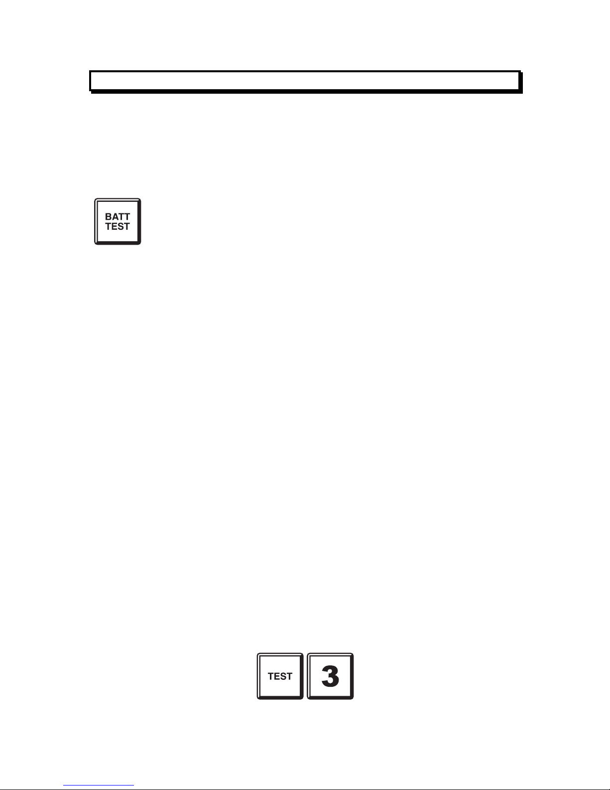
F4000 LCD Operator's Manual Document No: LT0117
Operating Instructions - System Functions
Page 6-2 19 April 2002 Issue 2.38
6.1 BATTERY TEST
6.1.1 FUNCTION
To initiate a test on the standby battery supply by applying a test load for one minute.
6.1.2 OPERATING SEQUENCE (LOCAL PANEL)
From any information display or base display press:
- The LCD displays "Testing battery. Press ACK to stop".
- The "CHGR/BATT FAULT" indicator turns ON rapid flashing to
indicate a battery test is in progress.
TO STOP THE BATTERY TEST WHEN RUNNING
- Press the "ACK" key.
IF THE TEST PASSES
- If after application of the test load for one minute, the battery
voltage is still within specification, then the test will terminate
and the LED indicator will turn OFF.
- The LCD displays "Battery test passed. Press ACK key".
- Press the "ACK" key to complete the test, and the LCD will
revert to its previous display.
IF THE TEST FAILS
- If during the test a battery low is detected, the test will
terminate and the "CHGR/BATT FAULT" LED indicator will
flash.
- The LCD displays "Battery test failed. Press ACK key".
- Press the "ACK" key to clear the display and flashing
"CHGR/BATT FLT" LED indicator.
6.1.3 OPERATING SEQUENCE – REMOTE PANEL
A prompt will be given requesting whether the local panel or a remote panel should be
tested. For the remote panel option a further prompt will be given for the SID of that panel.
Enter the SID of the remote panel to be tested. Then press:
To send the command to the remote panel.
Page 77

Document No: LT0117 F4000 LCD Operator's Manual
Operating Instructions - System Functions
Issue 2.38 19 April 2002 Page 6-3
6.1.4 NOTES
(a) The "CHGR/BATT FLT" LED indicator will flash for the rest of the 1 minute test
period if the battery test fails or until the test failure is acknowledged.
(b) Pressing the "ACK" key will turn OFF the "CHGR/BATT FLT" LED indicator if it is
flashing, and clear the test fail message on the LCD.
(c) If the battery test failed, perform another "Battery Test" after 24 hours. If the battery
test fails again please call your service company.
(d) It is not possible to initiate a Battery Test until FOUR (4) minutes after the end of a
previously passed battery test. A KEY ERROR tone will be sounded, and the LCD
will display "Cannot start battery test at present".
(e) There is a 1:4 "Failure to Next Test" inhibit time ratio.
For example: If the test fails after 30 seconds, it is not possible to initiate
another Battery Test until after 2 minutes (4 x 30 seconds).
(f) Pressing the "ACK" key at any time terminates the Battery Test.
(g) For New Zealand mode FIPs, no test load is applied to the battery. The FIP itself is
the only required load.
(h) A New Zealand mode FIP will initiate an automatic battery test at the Autotest Begin
time every day except Saturday, Sunday and for the user configured dates.
The test is applied for 1 hour and indicates as “Battery Testing” on the LCD. Any test
failure indication on the "CHGR/BATT FLT" LED indicator will last for the remainder
of the 1 hour test period, unless it is cleared by executing a SYSTEM FAULTS
RESET.
During automatic battery test failure, the FIP will signal DEFECT (FAULT) to the
brigade. An RZDU will signal battery low to the FIP, for a test failure.
(i) F4000 V2.31(N) or later FIPs can be programmed for battery disconnect monitoring.
If enabled, a battery test is briefly applied every 15 to 63 seconds (depending on the
programmed setting) to determine whether the battery is connected, i.e. it can supply
power to the system.
Page 78

F4000 LCD Operator's Manual Document No: LT0117
Operating Instructions - System Functions
Page 6-4 19 April 2002 Issue 2.38
6.2 BELL TEST
6.2.1 FUNCTION
To operate the Bell Output for a period of five (5) seconds.
6.2.2 OPERATING SEQUENCE
From any information display or base display press:
Note: For a networked panel after pressing SYSTEM a prompt will be given requesting
whether the local panel or a remote panel should be tested. For the remote panel
option a further prompt will be given for the SID of the remote panel. Enter the SID of
the remote panel to be tested.
Bell test can also be started by the TEST SYSTEM BELLS command sequence:
- The LCD briefly displays "Bells Test Started".
- The Bell Output is turned on for 5 seconds.
6.2.3 NOTES
(a) The Local Bell output will be turned on and the BEL token in the output logic will be
TRUE for the 5 second "BELL TEST", even if the BELLS are ISOLATED, or
externally silenced (New Zealand mode).
Page 79

Document No: LT0117 F4000 LCD Operator's Manual
Operating Instructions - System Functions
Issue 2.38 19 April 2002 Page 6-5
6.3 BELL ISOLATE or DE-ISOLATE
6.3.1 FUNCTIONS
To change the isolation state of the alarm bells, either from de-isolated to isolated, during
testing, or vice-versa on completion of tests.
6.3.2 OPERATING SEQUENCE – LOCAL PANEL
To Isolate or De-Isolate the bells at any time, press:
- If the amber "BELLS ISOLATED" LED indicator was OFF, it
will now be turned ON, to indicate the alarm bells are isolated.
- If the amber "BELLS ISOLATED" LED indicator was ON, it will
now be turned OFF, to indicate the alarm bells are de-isolated.
- When the Bells are isolated, New Zealand mode FIPs will turn
off the "NORMAL" indicator, and will slow pulse their internal
sounder if the door is closed.
- Note that the bells can also be isolated via the SYSTEM
ISOLATE BELLS or ISOLATE SYSTEM BELLS command
sequences.
NOTE: On New Zealand mode FIPs it is possible to silence the bells via operation of
the external Silence Alarms keyswitch on the FIP, an RDU, or another
network F4000. This will cause the "BELLS ISOLATED" LED to flash (2Hz or
slow), and a fault (defect) to be signalled to the brigade.
A bell isolate or de-isolate command may also be initiated by an RDU, if this
function has been enabled during programming at the RDU.
For network F4000s, isolating the local bells may result in the bells on other
FIPs on the system being silenced, depending on how the F4000s have been
configured.
6.3.3 OPERATING SEQUENCE – REMOTE PANEL
To Isolate/De-isolate the bells at remote panel nnn, press:
The status of the bells isolation at the remote panel will be given and pressing the ACK key
will invert this (e.g. change Isolated to De-isolated).
Page 80

F4000 LCD Operator's Manual Document No: LT0117
Operating Instructions - System Functions
Page 6-6 19 April 2002 Issue 2.38
6.4 LCD/LAMP (LED) TEST
6.4.1 FUNCTION
To momentarily turn all indicators on to visually inspect that they are working correctly, and
to test operation of the LCD.
6.4.2 OPERATING SEQUENCE
From any information display or base display, press:
Note: For a networked panel after pressing SYSTEM a prompt will be given requesting
whether the local panel or a remote panel should be tested. For the remote panel
option a further prompt will be given for the SID of the remote panel. Enter the SID of
the remote panel to be tested.
The display test can also be started by the TEST SYSTEM DISPLAYS command sequence.
For testing the LCD: - a test pattern is displayed, activating all LCD elements
on the first line. The "ACK" key must be pressed to
continue the test.
- When "ACK" is pressed, the same test pattern is
displayed on the second line of the LCD. The "ACK"
key must be pressed again to complete the test.
For testing the system status indicators and display boards:
- The internal and external System Status indicators are
turned ON.
- Each board of 16 Zone Indicators are then successively
turned on and off.
- Visually check that every indicator is turned ON at
some stage during this process.
- If any LED indicator does not light when the rest of the
board is, please call service.
NOTE: Any boards configured to be Relay Driver Boards will not be tested during the
Lamp Test.
On New Zealand mode FIPs a Lamp Test can also be started by momentarily shorting the
LAMP TEST- input on the display extender board input to 0V.
F4000 V2.31(N) or later can be programmed to activate the fault or alarm sounder when the
system status indicators are being tested.
Page 81

Document No: LT0117 F4000 LCD Operator's Manual
Operating Instructions - System Functions
Issue 2.38 19 April 2002 Page 6-7
6.5 SYSTEM TEST
6.5.1 FUNCTION
The System Test checks the integrity of the system hardware and software.
It applies simulated alarm and fault conditions to each circuit to check that the conditions are
detected and processed correctly. Analogue addressable smoke detectors and devices that
support testing are also tested to verify that an alarm condition can be generated by each
device.
6.5.2 OPERATING SEQUENCE
From any information display or base display, press:
Note: For a networked panel after pressing SYSTEM a prompt will be given requesting
whether the local panel or a remote panel should be tested. For the remote panel
option a further prompt will be given for the SID of the remote panel. Enter the SID of
the remote panel to be tested.
The System test can also be started by the TEST SYSTEM SYSTEM command sequence.
- The LCD displays "Testing system. Press ACK to stop". Pressing
"ACK" will abort the test.
- The "BELLS ISOLATED" and "ANCIL ISOLATED" LED indicators are
turned ON to indicate that the BELLS output and ANCIL outputs have
been automatically isolated for the duration of the test.
- The Master Alarm Facility is also automatically isolated, however this
is not indicated.
- Consequently, if any un-isolated MAF alarm or fault conditions exist,
the MAF will stop signalling these conditions to the brigade for the
duration of the test.
6.5.3 TEST OPERATION
The System Test operates as follows:
6.5.3.1 MEMORY TEST:
A test of the EPROM, RAM and EEPROM components of each microprocessor system is
initiated.
If this test fails the buzzer sounds its test fail cadence, the SYSTEM FAULT indicator comes
ON and the LCD displays a test fail message. Pressing "ACK" silences the buzzer and
clears the fail message from the LCD, but the SYSTEM FAULT indicator does not turn OFF
until the completion of a successful memory test.
Page 82

F4000 LCD Operator's Manual Document No: LT0117
Operating Instructions - System Functions
Page 6-8 19 April 2002 Issue 2.38
6.5.3.2 FAULT AND ALARM TEST:
The system test then applies "FAULT" and "ALARM" test signals to all enabled responder
inputs. The test is deemed complete when all Responders report that their tests have
passed.
The test fails either if all Responders do not complete their tests within a certain time, or if at
any time any of the tested circuits go into the incorrect state. If a failure is detected, this is
annunciated by the test fail cadence on the buzzer, a flashing FLT indicator on the failed
zone, and a fail message on the LCD. This suspends the test.
Press "ACK" to silence the buzzer and clear the fail message from the LCD. This aborts the
test. The SYSTEM FAULT indicator remains ON and can only be turned off by a successful
re-test.
If there is a test failure on a circuit input then the FLT LED indicator for the zone comes on
flashing if the applied test alarm or test fault signals were NOT detected; or the ALM and
FLT LED indicators come on flashing if there are any unexpected alarms or faults
respectively.
The ideal response to a system test is no new zone indicators ON rather than any indicators
on flashing, and a "System test passed. Press ACK key" message on the LCD.
If the system includes Analogue Addressable Responders (AARs) or Multiprotocol
Responders (MPRs), a successful test can take up to 2.5 minutes, otherwise about 1 minute
is required.
6.5.4 TEST ABORT
Pressing the "ACK" key during the test terminates the SYSTEM TEST.
Detection of an ALARM condition which seems unrelated to the applied test alarm (ie
possibly a genuine alarm) holds the test at the affected Responder and causes the ALM and
FLT indicators to flash for the zone in alarm, along with the FLT indicators for zones mapped
to by the circuit under test on the same responder.
However, since it is not established that it is a genuine alarm no MAF/ANCIL/BELL or other
mapped outputs will be activated. Pressing the "ACK" key takes the FIP out of test mode,
turning off the ALM indicator and buzzer if the alarm is no longer present. The system
reverts to normal operation. If the alarm is still present, this will be detected and
annunciated in the usual way.
Detection of FAULT conditions which are unrelated to the applied test fault conditions are
treated similarly, except that just the fault indicator of the suspect zone, and the zones
mapped to by the circuit under test on the same responder, come on flashing.
If the circuit under test is not mapped to a displayed zone, only the Service company can
determine the circuit failure from the internal log or by reviewing the history on the LCD.
If the circuit under test is not mapped to a zone at all, then the test is not terminated by a
failure but indicated at the end of the test by the buzzer and LCD "Test Fail" message.
Again the circuit failure can only be determined from the internal log, or by viewing the
history on the LCD.
Page 83

Document No: LT0117 F4000 LCD Operator's Manual
Operating Instructions - System Functions
Issue 2.38 19 April 2002 Page 6-9
6.5.5 NOTES
(a) System Test is not possible if any unacknowledged alarm or fault exists; or if an
automatic test sequence, battery test, zone test or auto-reset zone test is in progress.
ADR S/W earlier than Version V1.04 will fail the test if any circuit is in alarm or fault at
the start of the test.
(b) System Test bypasses any programmed time delays.
(c) If there is a test failure the "SYSTEM FAULT" indicator is left ON until a successful
test (SYSTEM or AUTOMATIC) is performed. However, this cannot be done until the
alarm or fault that terminated the test is cleared. Refer note (a) above.
(d) During Self Test and for a brief time afterwards, the refresh of data to RZDUs is
suspended, to ensure that any test failure information is not sent to the RZDUs, and
incorrectly interpreted as true ALARM or FAULT conditions.
Page 84

F4000 LCD Operator's Manual Document No: LT0117
Operating Instructions - System Functions
Page 6-10 19 April 2002 Issue 2.38
6.6 RECALL SYSTEM FAULTS
6.6.1 FUNCTION
Allows an operator to view on the LCD the current causes of a "SYSTEM FAULT" indication.
These include problems with the FIP, any Responder or RZDU that could be connected to
the FIP, or another panel on a networked system.
6.6.2 OPERATING SEQUENCE
From any information display or base display, press:
The display will pause briefly while the FIP searches for the first system fault. If none is
found, a brief message is displayed saying so, and the LCD reverts to the base display.
If a system fault exists, the LCD will display it. To view the next fault, press:
To view the previous fault, press:
Page 85

Document No: LT0117 F4000 LCD Operator's Manual
Operating Instructions - System Functions
Issue 2.38 19 April 2002 Page 6-11
6.6.3 NOTES
The search for system faults first tests for any FIP faults, followed by responder and RZDU
faults, and finally any Network FIP faults.
The LCD displays shows faults using a "Page" format, where each page is capable of
displaying a number of different faults, but only those faults that are actually present are
displayed.
There are up to 4 pages of faults for the FIP, one page per responder and RZDU, and up to
3 pages for each FIP on the network.
The display is "real time", and the display updates once per second. Consequently, if a fault
is transitory, the display will show and blank the indication as the fault occurs and clears.
If all faults have cleared before the NEXT or PREV key is pressed again, the display will
briefly display a message indicating that there are no more system faults, and then it will
revert to the base display.
The information that can be displayed for each fault page is as follows:
FIP Page 1
SWFlt - A Software Fault was latched.
E2CRC - The FIP has detected a bad database.
STstF - The System failed its Powerup, Self or Automatic Test.
Brk1 - No messages received by the FIP on Channel 1.
Brk2 - No messages received by the FIP on Channel 2.
NoPrc - FIP processing has been stopped.
FRsp0 - At some time, a foreign responder 0 was detected.
FIP Page 2
WDogL - The FIP has a latched watchdog indication.
DispF - There is a fault with the FIP LED display chain.
ChgrF - There is a Charger Fault at the FIP.
LpPwr - The FIP has detected an F4000 loop power fault.
BatLo - The FIP has a battery low condition.
BatFl - The FIP has a battery fail condition.
FIP Page 3 - NZ Mode FIPs Only
TEvac - Trial Evacuation active at FIP or RZDU.
SilAlm - Silence Alarms active at FIP or RZDU.
ExtDef - FIP External Defect Active.
ExtEvc - FIP External Evacuation Defect Active.
LatBVLo - FIP has latched a battery very low condition.
Abnml - FIP has an abnormal condition, e.g. EEPROM write enabled.
FIP Page 4
NetFlt - Network Fault present. Refer 6.6.4.
CmnPtI - A point on this FIP is isolated.
BattDis - The battery is disconnected.
MainsFl - The mains has failed.
DirtyAlert - One or more analogue detectors on this FIP are in Dirty Alert.
Page 86

F4000 LCD Operator's Manual Document No: LT0117
Operating Instructions - System Functions
Page 6-12 19 April 2002 Issue 2.38
NOTES (CONTINUED)
Responders - On a per Responder Basis
PRly - Responder has opened its Power Relay.
Scan - FIP is not receiving data from this responder.
Forgn - Responder is unconfigured, or more than one of same address.
TypeM - Type mismatch between actual responder type and the type stored in
the FIP database, or a SS database is being sent to an MPR that
cannot process it correctly.
Brk1 - No messages received by Responder on Channel 1.
Brk2 - No messages received by Responder on Channel 2.
RyBd - Relay Board fault.
L2F - AAR or MPR fault e.g. Top Board Fault, Power Line 2 Fault, or device
type mismatch.
RZDUs - On a per RZDU Basis
Forgn - Reply received from an unconfigured RZDU.
BatLo - Battery low at RZDU.
DispF - Display fault at RZDU.
BatFl - Battery fail at RZDU.
Scan - FIP is not receiving data from this RZDU.
StstF - RZDU failed its self test.
ChgrF - Charger fault at RZDU.
Network Panels Page 0
ScanF - The Local Panel is not receiving any data from the Remote panel
indicated.
LnkIA - The Local Panel is not receiving channel A test data from the Remote
panel indicated.
LnkIB - The Local Panel is not receiving channel B test data from the Remote
panel indicated.
SysFlt - The Remote Panel has a system fault.
NetFlt - The Remote Panel has a network fault.
Stdby - The Remote Panel has a standby condition.
Network Panels Page 1
Abnml - The Remote Panel has an Abnormal status present.
BellI - The Remote Panel's bells are isolated.
TEvac - The Remote Panel is asserting Trial Evacuation.
SilAlm - The Remote Panel is asserting Silence Alarms (Silence Bells)
BrigT - The Remote Panel is asserting Brigade Test.
SysFRcl - The Remote Panel has information that should be recalled on its own
LCD display using the System Fault recall command.
Network Panels Page 2
CmnPtI - A point on this FIP is isolated.
TstFlI - The FIP is signalling a test fail condition.
SysTst - The remote panel is currently executing a system test.
Page 87

Document No: LT0117 F4000 LCD Operator's Manual
Operating Instructions - System Functions
Issue 2.38 19 April 2002 Page 6-13
6.6.4 NETWORKED PANELS
If the local panel detects a network fault (e.g. it fails to receive messages from a remote
panel that it is expecting to receive from), or it receives a signal from a remote panel saying
that it has a system fault, then NetFlt will be shown.
If the cause of the fault was determined by the local panel (as distinct to receiving the signal
from the remote panel) then the actual type of fault will be logged to the printer and the
history. If the cause was signalled by the remote panel, then the status will be indicated on
one of the pages 0-3 for the remote panel.
If SysFRcl is shown for a remote panel, it may be necessary to carry out a Recall System
Fault at that panel itself to determine the exact cause of the fault.
Page 88

F4000 LCD Operator's Manual Document No: LT0117
Operating Instructions - System Functions
Page 6-14 19 April 2002 Issue 2.38
6.7 SYSTEM FAULT RESET
6.7.1 FUNCTION
To reset, if possible, a latched System Fault as shown by the front panel "SYSTEM FAULT"
indicator.
The specific cause, or causes, of the "SYSTEM FAULT" indication can be determined by a
"RECALL SYSTEM FAULT" command, or sometimes be seen on the internal diagnostic
indicators.
6.7.2 OPERATING SEQUENCE
From any information display or base display, press:
Note: For a networked panel after pressing SYSTEM a prompt will be given requesting
whether the local panel or a remote panel should be reset. For the remote panel
option a further prompt will be given for the SID of the remote panel. Enter the SID of
the remote panel to be reset.
System Fault Reset may also be effected by the RESET SYSTEM command sequence.
- The "WATCHDOG", "DISPLAY FAULT", and
"SOFTWARE FAULT" LED indicators (on the Main Board)
latch, to assist service personnel during trouble shooting.
- If an FIP loop power fault exists, the FIP immediately
disconnects power to the loop on line 2 (so long as no other
conditions exist that require that power be connected).
The FIP then tests as to whether the loop fault has cleared or
not.
- If a particular fault condition no longer exists, system fault reset
clears that fault indicator.
6.7.3 NOTES
(a) System Fault Reset should only be performed by Service Technicians or authorised
fire safety personnel.
(b) System Fault Reset should only be performed after a "Recall System Fault"
command has been used to determine the cause of the fault and any appropriate
service action has been taken.
(c) If the fault is a network fault then it will be cleared irrespective of whether it is still
present or has cleared. Thus if any faults still exist they will be re-annunciated soon
thereafter.
Page 89

Document No: LT0117 F4000 LCD Operator's Manual
Operating Instructions - System Functions
Issue 2.38 19 April 2002 Page 6-15
6.8 RECALL HISTORY
6.8.1 FUNCTION
The FIP keeps a list of the last 900 events in chronological order. The RECALL HISTORY
command allows an operator to view the historical list of events stored in the FIP, and to
move forwards and backwards through the list. When either end of the list is reached, the
LCD automatically shifts to the other end of the list and displays whether the event is the
newest or oldest.
6.8.2 OPERATING SEQUENCE
From any information display or base display, press:
The display will show the most recent history event.
To access the event that occurred before the event displayed, press:
If the PREV key is pressed when the event displayed is the oldest event, the LCD will briefly
display a message indicating that the event to be displayed is the most recent event and
then it displays that event.
To access the event that occurred after the event displayed, press:
If the NEXT key is pressed when the event displayed is the most recent event, the LCD will
briefly display a message indicating that the event to be displayed is the oldest event on
record, and then displays it.
Page 90

F4000 LCD Operator's Manual Document No: LT0117
Operating Instructions - System Functions
Page 6-16 19 April 2002 Issue 2.38
6.8.3 PRINTER/HISTORY EVENTS
The event printer output and history log for networked F4000s logs only local events, ie.
events and alarms from other panels are not logged. A Network Printer that prints network
events is available with the Protocol Translation Module (PTM), or Network Display Units
(NDU) or Networked F3200 FIPs.
There are, however, a number of additional events that can be produced by a networked
F4000. Those events relating to a remote panel are identified by a description of SID XX,
where XX is the SID of the panel that caused the event.
The new events are:
(i) NET SCAN FAIL/NORMAL - FAIL: the specified panel failed to communicate on the
network due to it being offline or there being a problem with the network cabling;
NORMAL:the panel began communicating again.
(ii) NET FOREIGN DEVICE - an unexpected panel is communicating on the Panel Link
Network for Link Integrity testing.
(iii) NET COMMAND ACCEPTED - a network command was received from the specified
panel and validated for further processing. The events immediately following this
event may have been the result of executing the received command.
(iv) NETWORK EVENT QUEUE OVERFLOW - the local F4000 was generating events
faster than it could send them onto the network. Some events will have been lost.
The lost events may have been recorded on the event printer or in the history log.
This event should occur only in cases of extreme network loading, many events
occurring on the FIP simultaneously or a network cable fault.
(v) NET MSG DISCARDED - the local F4000 discarded a message that was repeatedly
sent to another device on the network that did not acknowledge it. To allow other
messages to be sent on the network, the unacknowledged message was discarded.
Messages should be discarded only in cases of extreme network loading, if the
system addressed does not exist or if it is currently off line, or if network cables are
broken.
This event immediately generates a System Fault that will automatically clear itself
30 seconds after the last discard occurred.
Note that discards from SID 0 indicate that an acknowledgement to a broadcast was
not received.
Page 91

Document No: LT0117 F4000 LCD Operator's Manual
Operating Instructions - System Functions
Issue 2.38 19 April 2002 Page 6-17
6.9 SET SYSTEM TIME
6.9.1 FUNCTION
Allows an operator to set the time in the real-time clock within the FIP.
6.9.2 OPERATING SEQUENCE
To set the time, press:
The current time is displayed. Enter the new time, in 24 hour format. To separate the hours
from the minutes, press the POINT key.
E.g. To set the time to 13:52, press:
If the time is in the correct format and is a valid time, the FIP real time clock will be set to the
new time. The display reverts to the SET SYSTEM menu, so that other changes can be
made, if desired.
6.9.3 NOTES
Due to hardware limitations, the seconds of the real time clock cannot be set via the LCD.
Whenever the time is set, the seconds are forced to zero. Consequently, the time should be
entered before the next minute occurs, and the "ENTER" key pressed at the start of that
minute.
F4000 V2.30 onwards can be programmed for automatic daylight saving adjustment of the
real-time clock.
On a network one panel may be set up as the time/date master. Setting the time or date at
this panel will result in the new time/date being sent to other panels on the network. The
time/date master will also send out the time/date to other panels at 11:30pm each day and
on daylight saving changes.
Page 92

F4000 LCD Operator's Manual Document No: LT0117
Operating Instructions - System Functions
Page 6-18 19 April 2002 Issue 2.38
6.10 SET SYSTEM DATE
6.10.1 FUNCTION
Allows an operator to set the date in the real-time clock within the FIP.
6.10.2 OPERATING SEQUENCE
To set the date, press:
The current date is displayed. Enter the new date. To separate the day, month and year
numbers, press the "POINT" key.
E.g. To set the date to 14/07/93, press:
If the date is in the correct format and is a valid date, the FIP real time clock will be set to the
new date. The display reverts to the SET SYSTEM menu, so that other changes can be
made, if desired.
6.10.3 NOTES
On a network one panel may be set up as the time/date master. Setting the time or date at
this panel will result in the new time/date being sent to other panels on the network. The
time/date master will also send out the time/date to other panels at 11:30pm each day and
on daylight saving changes.
Page 93

Document No: LT0117 F4000 LCD Operator's Manual
Operating Instructions - System Functions
Issue 2.38 19 April 2002 Page 6-19
6.11 SET LCD ACCESS PASSWORD
6.11.1 FUNCTION
Allows an operator to change the LCD Access Password. This password, when entered
correctly, allows:
(i) Alteration of the password itself.
(ii) Alteration of the sensitivity settings of analogue detectors configured in the system.
6.11.2 OPERATING SEQUENCE
To set the LCD Access Password, press:
The LCD will prompt for the current password. Enter the current password. The LCD will
then prompt for the new password, which should be entered. The LCD will then prompt for
the new password again, to confirm that the new password was entered correctly the first
time.
The FIP will then store away the new password, and re-calculate the database CRC.
The display then reverts to the SET SYSTEM MENU, so that other SET SYSTEM changes
can be made, if required.
6.11.3 NOTES
(a) All passwords consist of 0 to 10 numeric digits.
(b) All passwords are echoed with * instead of the actual digits entered.
(c) The CLR key can be pressed to allow re-entry of a password if an operator is not
sure of what was previously entered.
(d) The LCD password can also be set by service personnel using the programming
terminal.
(e) The password cannot be altered if there is a System, Automatic or Powerup test in
progress, if the programming terminal has stopped processing, or if the EEPROM
cannot be written to.
Page 94
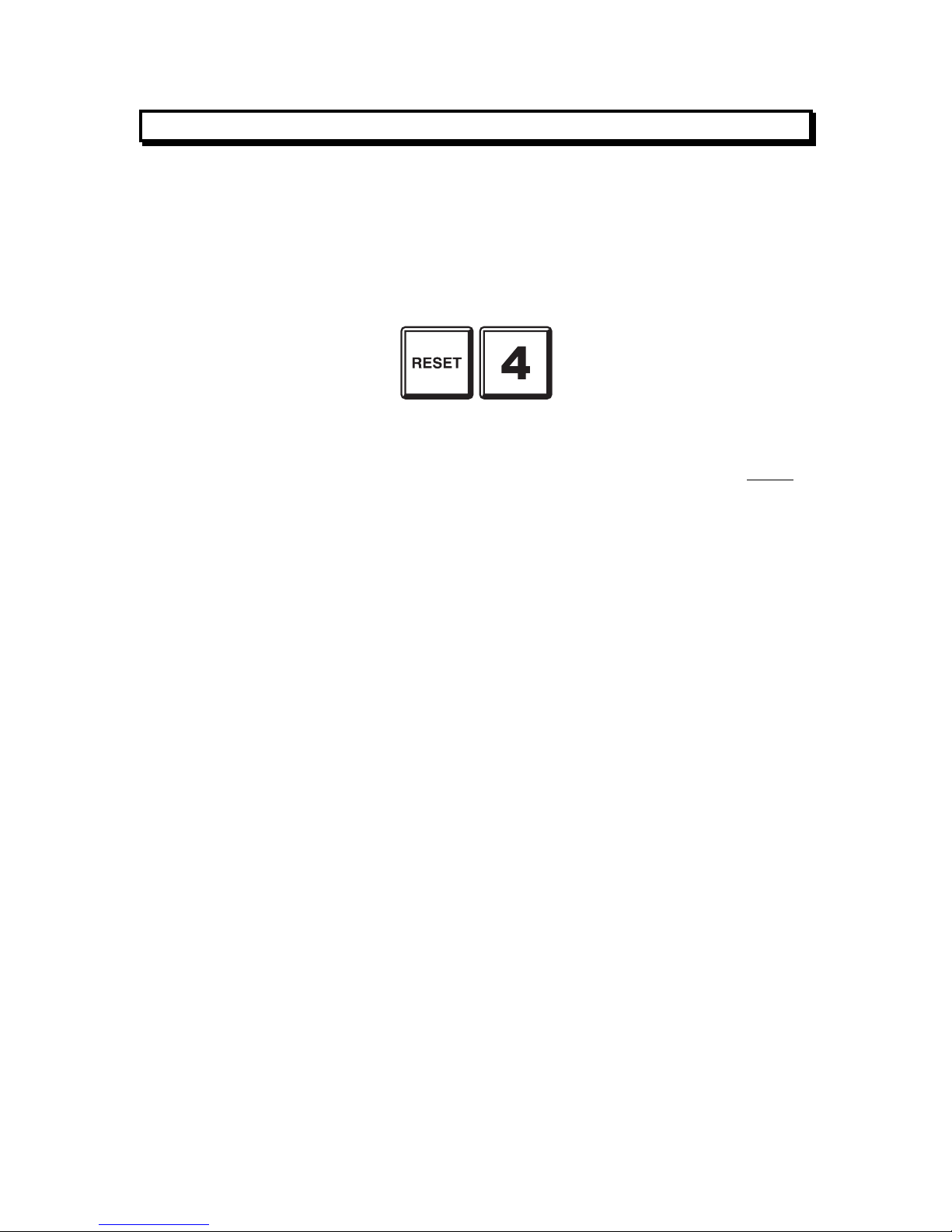
F4000 LCD Operator's Manual Document No: LT0117
Operating Instructions - System Functions
Page 6-20 19 April 2002 Issue 2.38
6.12 GLOBAL RESET
6.12.1 FUNCTION
To issue an FFCIF Type 2 Global Reset, to reset all un-isolated zones in alarm (if any) and
to signal RESET to the output logic.
6.12.2 OPERATING SEQUENCE
To issue a global reset from a base display, other than a Zone or Point Recall, press:
6.12.3 NOTES
(1) This command can be accessed from any base display or data recall display except
for the Zone Recall displays.
Press the "CLEAR" key to exit from a Zone or Point Recall display to the base
display before entering the Global Reset command.
(2) The Global Reset command will result in all unisolated zones in alarm being reset.
This may result in events being removed from the FFCIF Alarm List.
Page 95

Document No: LT0117 F4000 LCD Operator's Manual
Operating Instructions - System Functions
Issue 2.38 19 April 2002 Page 6-21
6.13 GLOBAL ISOLATE
6.13.1 FUNCTION
To issue an FFCIF type 2 Global Isolate, to isolate all un-isolated zones in alarm (if any) and
to signal ISOLATE to the output logic.
6.13.2 OPERATING SEQUENCE
To issue a global isolate from a base or information recall display, other than a Zone Recall,
press:
6.13.3 NOTES
(1) This command can be accessed from any base display or data recall display except
for zone recalls.
Press the "CLEAR" key to exit from a Zone Recall display before entering the Global
Isolate command.
(2) The Global Isolate command will result in all unisolated zones in alarm being
isolated. This may result in events being removed from the FFCIF Alarm List.
Page 96

F4000 LCD Operator's Manual Document No: LT0117
Operating Instructions - System Functions
Page 6-22 19 April 2002 Issue 2.38
6.14 RECALL SYSTEM CRCs
6.14.1 FUNCTION
Allows an operator to view on the LCD the Database CRC and the time and date the
database was last changed.
This information can be used as part of an AS1851.8 testing schedule, and to provide for
detection of tampering with the system configuration.
6.14.2 OPERATING SEQUENCE
From any information display or base display, press:
The Recall System CRCs display may also be accessed by the SYSTEM RECALL 3
command sequence from the base display.
The LCD will display the database CRC, and the time and date that the database was last
altered.
NOTE: Programming terminal database changes, or changing detector sensitivities or
the LCD password from the LCD keypad, will change the database and thus the
numbers displayed as a part of this recall.
Thus, if the database is changed, the new numbers should be recorded in the log
book and the service company advised.
Page 97

Document No: LT0117 F4000 LCD Operator's Manual
Operating Instructions - Zone Functions
Issue 2.38 19 April 2002 Page 7-1
7 OPERATING INSTRUCTIONS - ZONE FUNCTIONS
Page 98

F4000 LCD Operator's Manual Document No: LT0117
Operating Instructions - Zone Functions
Page 7-2 19 April 2002 Issue 2.38
7.1 ZONE ALARM OR FAULT TEST
7.1.1 FUNCTION
To test the circuit inputs of a selected alarm zone and send test alarm signals to the Brigade.
Two tests can be performed:
(a) A true fault simulation test, or
(b) A true alarm simulation test.
WARNING: This test performs a true zone test, time delays operate, and all outputs
operate, including MASTER ALARM OUTPUT, unless the zone is isolated.
Testing a Local Zone is covered in Section 7.1.2 and a Remote Networked Zone is covered
in Section 7.1.5.
7.1.2 OPERATING SEQUENCE (LOCAL ZONE)
OPTION: To prevent mapped outputs from operating "ISOLATE" the zone first.
Refer to "Zone Isolate or De-Isolating" section.
From the zone status recall display for the zone to be tested, press:
OR
From other information displays or the base display, press:
OR
where n n n is the number of the zone to test.
- The relevant test signal is applied to all circuits on the zone.
- Once all the circuits have gone into the test state, the relevant zone indicator
and fault sounder are turned on, if that zone is not isolated. FFCIF mode may
be entered if the zone being alarm tested is mapped to the MAF.
The LCD displays a test pass message, and pressing the "ACK" key clears
the test.
- If any circuit does not enter the correct state in response to the test signal,
then the test fails, the relevant zone indicator stays OFF and the buzzer
sounds its "TEST FAIL" cadence. The LCD displays a test fail message, and
pressing the "ACK" key clears the test.
Page 99

Document No: LT0117 F4000 LCD Operator's Manual
Operating Instructions - Zone Functions
Issue 2.38 19 April 2002 Page 7-3
7.1.3 ABORT ZONE TEST
Press the "ACK" key at any time to abort the ZONE TEST function.
- Zone circuits under test are returned to normal.
7.1.4 NOTES
(a) An Alarm detected on the zone under test when one is not expected (eg during the
FAULT test) is processed normally and the test aborted. Similarly, faults during the
ALARM test activate the fault sounder and may terminate the test.
(b) During the zone test sequence any other zones to which the tested circuits are
mapped behave as they normally would given FAULT and ALARM conditions.
(c) All alarm processing delays (AVF sequences, etc) are still active so the alarm
response time may be up to 60 seconds, depending on the circuit type.
(d) An AVF delay sequence initiated by a zone alarm test continues if the zone test is
aborted by the "ACK" key before the test has passed. That is, an alarm re-test of the
same zone within 120 sec will give an instant alarm.
(e) The test condition is automatically removed from the circuits after 120 seconds.
(f) Alarms or faults on any circuits zones other than those under test will abort the test
and remove all test signals. The alarm or fault is then treated normally.
(h) On Flow Switch Zones the test relay will operate for 2 minutes. If no alarm is
received within that time, the test will fail.
(i) It is not possible to start a zone test if there is an un-acknowledged alarm or fault
present; or if there is an Auto, System, Battery, Zone or Auto-Reset Test in progress.
Also, Flow Switch Zones cannot be tested if they do not have any relay programmed for
alarm testing.
7.1.5 OPERATING SEQUENCE (NETWORKED ZONE)
OPTION: To prevent mapped outputs from operating "ISOLATE" the zone first.
From the zone status recall display for the zone to be tested, press:
Page 100

F4000 LCD Operator's Manual Document No: LT0117
Operating Instructions - Zone Functions
Page 7-4 19 April 2002 Issue 2.38
From other information displays or the base display, press:
OR
Where nnnnn is the number of the network zone to be tested. (Refer Section 2.5.1 for
networked zone numbering).
If nnnnn is a network zone, the network test prompt is displayed, querying for the type of test
to be performed:
Press
for alarm test
for fault test
for operate test
for auto reset test
to abort a test in progress
The F4000 will then send the test command to the FIP with the selected zone on it.
 Loading...