

Page 1

F3200
FIRE INDICATOR PANEL
INSTALLATION & PROGRAMMING MANUAL
F3200 PRODUCT MANUAL
Document Number: LT0122
Issue .......... 2.7; 5 July 2001
-- A P P R O V A L S --
AUSTRALIAN STANDARD AS1603.4 1987 (Incl. Amdt 1 & 2)
AUSTRALIAN STANDARD AS4050(INT) 1992
- SSL Listing Number afp789
AUSTRALIAN STANDARD AS3548 1995 Class A
The F3200 Fire Indicator Panel is manufactured for
Tyco Services Fire & Safety
25 Cleeland Road
Oakleigh South
VIC 3167
AUSTRALIA
Tel : +61-3-9543 2220
Fax : +61-3-9543 2155
COPYRIGHT (C) 2001
Information contained in this document is subject to copyright, and shall not be reproduced
in any form whatsoever, without the written consent of Tyco Services Fire & Safety.
Information contained in this document is believed to be accurate and reliable, however
Tyco Services Fire & Safety reserves the right to change the content without prior notice.
Page 2

F3200 Installation & Programming Manual Document No: LT0122
TYCO SERVICES FIRE & SAFETY
END USER LIABILITY DISCLAIMER
The F3200 Fire Indicator Panel has a configuration programming facility which may be
accessed from the keypad by using a password.
This programming facility allows the user to define detail of the operation of the F3200
System which is being customised. It is possible for the user to program operational
features that prevent the installed FIP from meeting statutory requirements.
Tyco Services Fire & Safety does not accept responsibility for the suitability of the functions
programmed by the user.
Page ii 5 July 2001 Issue 2.7
Page 3

Document No: LT0122 F3200 Installation & Programming Manual
TABLE OF CONTENTS
End User Liability Disclaimer ...................................................................................................ii
Amendments .......................................................................................................................... vi
CHAPTER 1 INTRODUCTION...............................................................................1-1
1.1 SCOPE....................................................................................................................................1-2
1.2 ASSOCIATED DOCUMENTATION........................................................................................1-3
1.3 PRODUCT HISTORY LOG.....................................................................................................1-4
1.4 GLOSSARY OF ABBREVIATIONS .......................................................................................1-6
1.5 GLOSSARY OF TERMINOLOGY ..........................................................................................1-7
CHAPTER 2 SYSTEM DESCRIPTION.................................................................. 2-1
2.1 OVERVIEW .............................................................................................................................2-2
2.2 PHYSICAL STRUCTURE .......................................................................................................2-7
2.3 SYSTEM STRUCTURE.........................................................................................................2-10
CHAPTER 3 SYSTEM SPECIFICATIONS.............................................................3-1
3.1 GENERAL...............................................................................................................................3-2
3.2 MECHANICAL SPECIFICATIONS .........................................................................................3-3
3.3 ELECTRICAL SPECIFICATIONS...........................................................................................3-4
3.4 INPUT SPECIFICATIONS.......................................................................................................3-8
3.5 OUTPUT SPECIFICATIONS.................................................................................................3-14
3.6 CONTROLS ..........................................................................................................................3-19
3.7 DISPLAYS.............................................................................................................................3-20
CHAPTER 4 ORDERING INFORMATION............................................................. 4-1
4.1 ORDERING INFORMATION...................................................................................................4-2
CHAPTER 5 CONFIGURING A FIP....................................................................... 5-1
5.1 GENERAL...............................................................................................................................5-2
5.2 MODULE CONFIGURATION..................................................................................................5-2
5.3 BATTERY & POWER SUPPLY..............................................................................................5-3
5.4 LINKS ON PCB MODULES..................................................................................................5-11
5.5 ERROR MESSAGES DURING FIP CONFIGURATION.......................................................5-12
CHAPTER 6 PROGRAMMING.............................................................................. 6-1
6.1 INTRODUCTION.....................................................................................................................6-2
6.2 SET MENU & OPERATOR PROGRAMMING FUNCTIONS ...............................................6-12
6.3 INITIALISING, ACCESSING, DE-ACCESSING, PRINTING, SAVING, LOADING &
VERIFYING THE DATABASE.............................................................................................6-13
6.4 PROGRAM DATA MENU, TEXT & GLOBAL PARAMETERS............................................6-17
CHAPTER 7 PROGRAMMING SYSTEM CONFIGURATION............................... 7-1
7.1 SYSTEM CONFIGURATION MENU.......................................................................................7-2
7.2 CONFIGURING CIRCUITS (AZCS)........................................................................................7-6
7.3 CONFIGURING ZONES........................................................................................................7-11
7.4 PROGRAMMING OUTPUTS................................................................................................7-13
7.5 RELAY SUPERVISION.........................................................................................................7-33
7.6 RDU.......................................................................................................................................7-35
CHAPTER 8 INSTALLATION & WIRING..............................................................8-1
8.1 INSTALLATION ......................................................................................................................8-2
8.2 FIELD WIRING........................................................................................................................8-8
Issue 2.7 5 July 2001 Page iii
Page 4

F3200 Installation & Programming Manual Document No: LT0122
8.3 AZC WIRING.........................................................................................................................8-10
8.4 MAF ANCILLARY RELAY WIRING .....................................................................................8-12
8.5 WARNING SYSTEM WIRING...............................................................................................8-15
8.6 MODULE RELAY WIRING ...................................................................................................8-20
8.7 OPEN COLLECTOR WIRING...............................................................................................8-22
8.8 ASE INSTALLATION AND WIRING ....................................................................................8-23
8.9 RDU WIRING.........................................................................................................................8-24
8.10 SLIMLINE NDU (FP0714) WIRING......................................................................................8-26
8.11 INSTALLATION OF 19" NDU (FP0733)..............................................................................8-26
CHAPTER 9 APPLICATIONS................................................................................9-1
9.1 AS1668 AIR CONDITIONING CONTROL..............................................................................9-2
9.2 GAS FLOOD ...........................................................................................................................9-9
9.3 SUB FIP MONITORING........................................................................................................9-19
9.4 FIRE DETECTION IN HAZARDOUS AREAS (EXPLOSIVE ATMOSPHERES) .................9-22
9.5 USE OF NORMALLY CLOSED CONTACTS.......................................................................9-32
9.6 SPECIAL CONNECTIONS TO DETECTORS......................................................................9-33
CHAPTER 10 ALIGNMENT, ADJUSTMENT & PLACING INTO OPERATION.. 10-1
10.1 ALIGNMENT & ADJUSTMENT...........................................................................................10-2
10.2 PLACING INTO OPERATION .............................................................................................10-3
CHAPTER 11 NETWORK PROGRAMMING....................................................... 11-1
11.1 INTRODUCTION ..................................................................................................................11-2
11.2 PROGRAMMING METHODS ..............................................................................................11-4
11.3 NETWORK CONFIGURATION MENU................................................................................11-9
11.4 SID CONFIGURATION ......................................................................................................11-12
11.5 NETWORK MAF CONFIGURATION.................................................................................11-14
11.6 NET COMMANDS..............................................................................................................11-15
11.7 NET FFCIF CONFIGURATION..........................................................................................11-16
11.8 NETWORK EVENT CONFIGURATION.............................................................................11-18
11.9 NETWORK LOGIC VARIABLES.......................................................................................11-20
11.10 NET STATUS REFRESH...................................................................................................11-21
11.11 NDU OPERATION..............................................................................................................11-22
11.12 DEFAULT VALUES FOR PANEL-LINK VARIABLES......................................................11-24
CHAPTER 12 NEW ZEALAND OPERATION......................................................12-1
12.1 GENERAL ............................................................................................................................12-2
12.2 NZ DISPLAY EXTENDER BOARD .....................................................................................12-2
12.3 MANUAL CALLPOINT (MCP) .............................................................................................12-4
12.4 PROGRAMMABLE OPTIONS.............................................................................................12-5
12.5 LOGIC TOKENS ..................................................................................................................12-6
12.6 SYSTEM STATES & INDICATIONS....................................................................................12-7
12.7 NETWORK PARAMETER PROGRAMMING......................................................................12-8
12.8 INSTALLATION : NZ DISPLAY EXTENDER BOARD & BRIGADE DISPLAYS .............12-10
CHAPTER 13 TANDEM LCD MODE................................................................... 13-1
13.1 TANDEM LCD MODE ..........................................................................................................13-2
APPENDIX A COMPATIBL E ACTUATING DEVICE S (DETE CTO R S).......................A-1
APPENDIX B F3200 CONFIGURATION SHEETS....................................................... B-1
Page iv 5 July 2001 Issue 2.7
Page 5

Document No: LT0122 F3200 Installation & Programming Manual
AMENDMENTS
ISSUE DATE COMMENTS ECN
1 20/04/94 Original. Corresponds to V1.10 software, which
includes RZDUs, multiple access codes, revised print
menu, NSW Coder, Programmable Alarm Text, Inst
Alarm Text (not in V1.01)
2 30/01/95 Was WP5.1. Upgraded for small FIP,6A PSU.
Upgraded ordering info, AS1668 Application, Detector
List and added I.S.(9.4). Also some
corrections.
2.1 01/02/96 Auto-Test Disable note added to 6.4.4.
Note 10 (Pg A-5) modified.
Table III updated.
Applications note 9.5 added.
PA0443 added to Ordering Info P4-5.
2.2 16/04/96 Deleted paragraph headed "C29BEx" in Section
9.4.3.4.
2.3 01/12/97 F3200 V2.00 software release.
Chapters 6, 7 modified.
Network programming Chapter 11 added.
Daylight saving, output logic control of zone LEDs,
selectable event types for history and printing,
database verify, database CRC recall.
Controller Board was 1931-2-1.
2.4 09/04/98
2.5 22/03/99 V2.06 software. Section 1.3 add V2.06. Section 6.4.4
2.6 14/06/00 Corresponds to V2.07/V2.08 software. Changes
2.7 05/07/01 Corresponds to V2.09 software. New buzzer mode &
Section 1.3.2 add V2.01-V2.04 details.
"Minute" timers 65-72, Section 3.8.
Section 4.1 new part numbers, Figs 6.1.2 and 7.1.1.
Fault Action Text & PC Programming Section 6.4.3.
RDU zone name transmission Section 7.6. Output
logic commands for zone isolate, zone de-isolate, and
zone reset, Section 7.4.9. RDU wiring Section 8.8.
Add AS/NZ 3548 Class A warning.
Bells/Ancil Isol key disabling; mains frequency
50/60Hz. Section 11.3.5, 11.11, 11.12 ACK
Broadcast Specific SID. System Configuration Sheets
Page 2 and Network Parameters.
throughout but mainly Sections 5.5, 5.6, 6.3.7, 6.4.4
and Chapters 12 and 13 added.
sounder silence options in Chapter 6. Sect 7.2.4
change to SAD type. Section 7.4.6 SNA option new.
Section 7.5 Relay supervision. Appendix A Simplex
detectors. Appendix B modified. Section 3.3.5.2 NDU
Quiescent current added. Section 12.8 NZ mode
installation added.
Chapter 8 Installation revised and Section 9.2 Gas
Flood revised. Complete re-print.
2162
2360
2417
2620
2709
2742
2937
3079
3165
3154
Issue 2.7 5 July 2001 Page v
Page 6

F3200 Installation & Programming Manual Document No: LT0122
THIS PAGE IS INTENTIONALLY LEFT BLANK
Page vi 5 July 2001 Issue 2.7
Page 7

Document No: LT0122 F3200 Installation & Programming Manual
Introduction
CHAPTER 1
INTRODUCTION
Issue 2.7 5 July 2001 Page 1-1
Page 8

F3200 Installation & Programming Manual Document No: LT0122
Introduction
1.1 SCOPE
This manual provides information for the personnel responsible for planning, ordering,
installing and programming an F3200 Fire Alarm System. It is assumed that such staff have
been trained to plan/install fire alarm equipment and are familiar with the relevant standards.
The manual is divided into the following chapters:
Chapter 1 Introduction: Information on this manual.
Chapter 2 System Description: A description of the structure of the F3200 FIP.
Chapter 3 Specifications: A detailed specification for the F3200 FIP.
Chapter 4 Ordering Information: Part numbers for the various system components.
Chapter 5 Configuring a FIP: General information and detail on fitting of various links
and resistors when configuring a system.
Chapter 6 Programming: An introduction to programming and a description of the
programming menus and global parameters.
Chapter 7 System Configuration: Detail on specific programmable options in the FIP
I/O.
Chapter 8 Installation & Wiring: Detail of installation and field wiring.
Chapter 9 Applications: Detail of configuration and wiring for specific applications.
Chapter 10 Alignment, Adjustment & Placing Into Operation: Detail on how to adjust an
F3200 in the field and place it into operation.
Chapter 11 Networking: Detail on programmable options for networked F3200s and
NDUs.
Chapter 12 NZ Operation: Describes operation of the NDU in NZ mode.
Chapter 13 Tandem LCD Mode: Describes operation of Tandem LCD mode.
Appendix A 1. Compatible Detectors: A list of detectors which are approved for use
with F3200.
2. Detector Configuration: Detail on AZC and zone configuration for
specific detector types.
Appendix B Configuration Forms: A set of master forms for recording programming detail.
Page 1-2 5 July 2001 Issue 2.7
Page 9

Document No: LT0122 F3200 Installation & Programming Manual
Introduction
1.2 ASSOCIATED DOCUMENTATION
1.2.1 PRODUCT
Additional information on the AS1603.4 approved F3200 FIP is found in the following product
manuals.
F3200 Operator's Manual A guide to the operation and maintenance of the F3200 FIP.
Part Number LT0119 is a loose A4 version.
Part Number LT0120 is a bound A5 version.
F3200 Technical Manual A technical description of the F3200 system and modules.
Part Number LT0121.
F3200 Installation & This manual.
Programming Manual Part Number LT0122.
F3200 Panel-Link Upgrade Upgrade instructions on how to make the F3200 panel
and Installation Manual network capable. Part Number LT0198.
Information on the AS4428.1 approved F3200 is found in the following manuals:
F3200 AS4428.1 Operator’s Manual For panels that comply with AS4428.1
LT0251 is in A4, loose leaf form.
LT0250 is in A5, bound form.
F3200 AS4428.1 Installation & Provides information for designing, installing
Configuration Manual and commissioning an F3200 and NDU. Part
Number LT0255.
F3200 AS4428.1 Programming Manual Provides information for programming
an F3200 and NDU. Part Number LT0256.
1.2.2 STANDARDS
This manual makes reference to the following Australian and New Zealand Standards:
AS1603.4 Automatic Fire Detection and Alarm Systems
Part 4 - Control and Indicating Equipment.
AS4050 (int) Fire Detection and Fire Alarm Systems - Fire Fighter's Control
and Indicating Facilities.
AS1668 SAA Mechanical Ventilation and Airconditioning Code.
AS1670.1 Automatic Fire Detection and Alarm Systems - System Design,
Installation and Commissioning.
AS4428.1 Fire Detection, Warning, Control and Intercom Systems -
Control and Indicating Equipment
Part 1 : Fire
NZS4512 Automatic Fire Alarm Systems in Buildings
Issue 2.7 5 July 2001 Page 1-3
Page 10

F3200 Installation & Programming Manual Document No: LT0122
Introduction
1.3 PRODUCT HISTORY LOG
1.3.1 HARDWARE
Part No. Description
PA0490 Controller/ A 1 11/11/93 1931-2
Display A 2 24/02/94
PA0491 MAF/PSU A 1 13/10/93 1931-3
B 2 28/02/94
PA0492 8 ZONE MODULE A 1 27/09/93 1931-4
PA0493 8 RELAY MODULE A 1 10/09/93 1931-5
PA0773 RS485 Comms Bd C 4 10/04/01 1901-139
PA0797 F3200 B 3 04/02/99 1931-84-1
Controller/ C 4 02/05/00
Display
PA0804 F3200 B 2 29/09/97 Used as replace-
Networkable C 4 02/05/00 ment board for all
Controller/ F3200/NDU panels
Display 1931-84-1
Iss Rev Date Drawing
A 3 16/06/94
B 3 10/06/94
B 4 21/02/95
B 5 14/05/97
C 6 11/11/97
D 9 14/05/01
A 2 29/04/99
A 2 22/09/99
1.3.2 SOFTWARE
Part No. Description
SF0089 F3200 EPROM V1.00 12/12/93 Pre-production
SF0089 F3200 EPROM V1.01 24/02/94 1st production
SF0089 F3200 EPROM V1.10 13/05/94 Includes RZDU, multiple
SF0164 F3200 EPROM V2.00 Nov. 1997 Networking
SF0175 NDU EPROM V2.00 Nov. 1997 First Release
SF0178 F3200 EPROM V2.00 Nov. 1997 Non-networking
SF0164 F3200 EPROM V2.01 Feb. 1998 F3200 Networked
SF0175 NDU EPROM V2.01 Feb. 1998
SF0178 F3200 EPROM V2.01 Feb. 1998 Non-Networked
SF0178 F3200 EPROM V2.02 Mar. 1998 Non-Networked
SF0164 F3200 EPROM V2.03 April 1998 F3200 Networked
SF0175 NDU EPROM V2.03 April 1998
SF0178 F3200 EPROM V2.03 April 1998 Non-Networked
SF0164 F3200 EPROM V2.04 August 1998 Networked
SF0175 NDU EPROM V2.04 August 1998
SF0178 F3200 EPROM V2.04 August 1998 Non-Networked
Revision Date Comments
access, etc.
SF0164 F3200 Net EPROM V2.05 Feb 1999
SF0175 NDU EPROM V2.05 Feb 1999
SF0178 F3200 Std EPROM V2.05 Feb 1999
Page 1-4 5 July 2001 Issue 2.7
Page 11

Document No: LT0122 F3200 Installation & Programming Manual
Introduction
SOFTWARE HISTORY LOG (CONTINUED)
SF0164 F3200 Net EPROM V2.06 Mar 1999
SF0175 NDU EPROM V2.06 Mar 1999
SF0178 F3200 Std EPROM V2.06 Mar 1999
SF0229 F3200, Std Panel, c/w Tandem V2.07 May 2000
SF0230 F3200, Networked, c/w Tandem V2.07 May 2000
SF0231 NDU, c/w Tandem V2.07 May 2000
SF0229 F3200, Std Panel, c/w Tandem V2.08 July 2000
SF0230 F3200, Networked, c/w Tandem V2.08 July 2000
SF0231 NDU, c/w Tandem V2.08 July 2000
SF0229 F3200, Std Panel, c/w Tandem V2.09 May 2001
SF0230 F3200, Networked, c/w Tandem V2.09 May 2001
SF0231 NDU, c/w Tandem V2.09 May 2001
Issue 2.7 5 July 2001 Page 1-5
Page 12

F3200 Installation & Programming Manual Document No: LT0122
Introduction
1.4 GLOSSARY OF ABBREVIATIONS
The following abbreviations are used throughout this manual:
A/C : Air Conditioning
ac : Alternating Current
AEOL : Active End of Line
AHr : Ampere Hour
ANC 1 : Ancillary Relay 1
AZC : Alarm Zone Circuit, or Detection Zone
AZF : Alarm Zone Facility, or Group
AVF : Alarm Verification Facility, or Check Alarm
Bd : Board
CIE : Control & Indicating Equipment
Char : Character
CCT : Circuit
COM : COMMON relay contact
dc : Direct current
EEPROM : Electrically Erasable Programmable Read Only Memory
ELV : Extra Low Voltage
EOL : End Of Line (device)
EOLR : End of Line Resistor
Expn : Expansion
E2 : Electrically Erasable Programmable Read Only Memory ....
FFCIF : Fire Fighter's Control & Indicating Facility
FIP : Fire Indicator Panel
FRC : Flat Ribbon Cable
I/O : Input/Output
LCD : Liquid Crystal Display
LED : Light Emitting Diode
MAF : Master Alarm Facility
Max : Maximum
Min : Minimum
MCP : Manual Call Point (Break Glass Switch)
MOV : Metal Oxide Varistor (Used for Surge Protection)
msec : Millisecond
NC : Normally Closed
NO : Normally Open
No : Number
Nom : Nominal
PC : Personal Computer (small computer)
PCB : Printed Circuit Board
PSU : Power Supply Unit
PTC : Positive Temperature Co-efficient (Thermistor)
R1 : Module Relay Number 1 (program abbreviation)
RL1 : Module Relay Number 1 (text abbreviation)
RAD : Return Air Duct (Air Conditioning Plant)
RMS : Root Mean Square
Reqd : Required
RTC : Real Time Clock
RZDU : Remote Zone Display Unit
SAD : Supply Air Duct (Air Conditioning Plant)
SID : System Identification Number (Network device)
sq mm : square millimetre
T1 : Programmable Timer Number 1 (program abbreviation)
Tmnl : Terminal
V1 : Programmable Variable Number 1
Page 1-6 5 July 2001 Issue 2.7
Page 13

Document No: LT0122 F3200 Installation & Programming Manual
Introduction
GLOSSARY OF ABBREVIATIONS (CONTINUED)
VA : Volts Amperes
VB : Battery Backed Voltage
VNB : Non Battery Backed Voltage
+VBF : Fused Battery-Backed Voltage
+VNBF : Fused Non-Battery-Backed Voltage
Z1 : Zone Number 1 (program abbreviation)
Zn1 : Zone Number 1 (text abbreviation)
8RM : 8 Relay Module
8ZM : 8 Zone Module
1.5 GLOSSARY OF TERMINOLOGY
The following terminology is used throughout this manual:
Ancillary Equipment : Equipment external to Fire Alarm system
Ancillary Relay : Relay in FIP which operates Ancillary equipment
Auto-Reset : Mode for one person testing of detectors
Auxiliary Output : Output for driving additional LEDs/relays
Baud : Bits per second
Control Output : Output from FIP to other equipment
Default : Pre-programming option or logic equation i.e. one that exists
without the user programming it.
Detector : Alarm Detection Device (electrical transducer)
Fire Control Station : Fire Brigade Authority, or any other authority which receives
the FIP alarm signals.
Mapping : Programmable causal relationship between inputs and outputs
Zone : Fire searchable area of building represented by a unique
number and name in the FIP, and associated with the AZC of
the same number.
Issue 2.7 5 July 2001 Page 1-7
Page 14

F3200 Installation & Programming Manual Document No: LT0122
Introduction
THIS PAGE INTENTIONALLY LEFT BLANK
Page 1-8 5 July 2001 Issue 2.7
Page 15

Document No: LT0122 F3200 Installation & Programming Manual
System Description
CHAPTER 2
SYSTEM DESCRIPTION
Issue 2.7 5 July 2001 Page 2-1
Page 16

F3200 Installation & Programming Manual Document No: LT0122
System Description
2.1 OVERVIEW
2.1.1 GENERAL
The F3200 is a self-contained, modular, intelligent Fire Indicator Panel (FIP) which performs
the functions of the Control and Indicating Equipment (CIE) as specified by the Australian
Standard AS1603.4 Automatic Fire Detection and Alarm Systems.
It is also available in formats that comply with AS4428.1. Refer to the relevant manuals that
apply to the AS4428.1 approved products.
The F3200 has a high degree of flexibility and expandability, catering for medium to very
large buildings from 8 zones or less, to 64 zones maximum. Refer to the constraints
specified in Section 3.1.3. More panels and zones can be added through the use of the
Vigilant Panel-link Network and the appropriate networkable F3200s.
This manual is also used for the installation of an NDU (Network Display Unit). NDU
operation is described in Section 11.11. An NDU may be programmed to operate in either
Australian mode (default) or New Zealand mode, and the operation of an NDU in New
Zealand mode is described in Chapter 12.
2.1.2 DETECTOR CIRCUITS
The F3200 detector interface electronics caters for a wide range of detectors, including
various types which have high alarm current requirements. It also caters for interfacing to:
Intrinsically safe circuit barriers/isolators (hazardous areas).
Long line circuits e.g. from a sub-indicator FIP.
Tamper-proof circuits e.g. for water valve supervision.
A full range of compatible detectors is listed in the Appendix A.
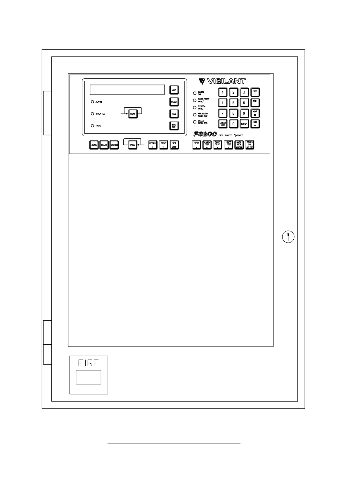
2.1.3 DISPLAYS
The primary display of the F3200 is a 2 line by 40 character LCD on which status messages
and prompts are shown. The LCD has backlight illumination which is turned on when there
is an alarm or operator interaction.
Common conditions such as zone ALARM, ISOLATED and FAULT, and various system
states such as BELLS ISOLATED are displayed on LEDs adjacent to the LCD.
The display panel composed of the LCD, LEDs and operator keypad meets the requirements
of AS4050 (int) for a Fire Fighter's Control and Indicating Facility (FFCIF).
As an optional extra, individual zone status (ALARM, ISOLATE and FAULT) can be
displayed on LEDs by fitting the appropriate number of 16 Zone LED Display Bds.
The F3200 electronics includes, as standard, an open collector transistor output for each
zone which can be used to drive an internal or remote mimic display.
Page 2-2 5 July 2001 Issue 2.7
Page 17
Document No: LT0122 F3200 Installation & Programming Manual
System Description
FIG 2.1.1
F3200, STANDARD CABINET - FRONT VIEW
Issue 2.7 5 July 2001 Page 2-3
Page 18
F3200 Installation & Programming Manual Document No: LT0122
System Description
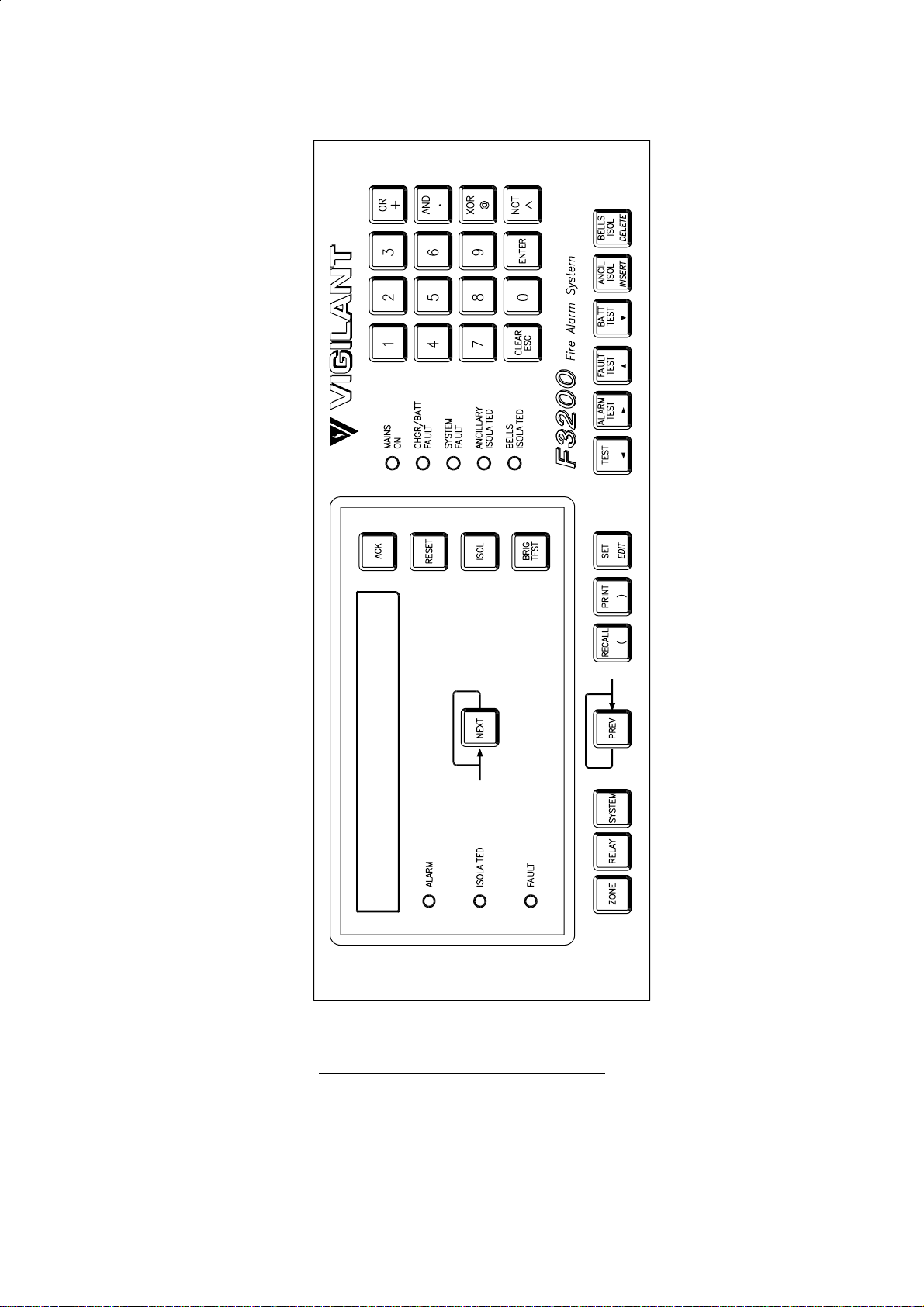
FIG 2.1.2
F3200 OPERATOR DISPLAY PANEL
Page 2-4 5 July 2001 Issue 2.7
Page 19
Document No: LT0122 F3200 Installation & Programming Manual
System Description
FIG 2.1.3
F3200 - SMALL CABINET
Issue 2.7 5 July 2001 Page 2-5
Page 20

F3200 Installation & Programming Manual Document No: LT0122
System Description
2.1.4 OUTPUTS
The F3200 MAF/PSU Module provides 7 relays as standard. These are used for signalling
to the Brigade (Fire Control Station) and for switching alarm bells and ancillary equipment
such as door holders, airconditioning shutdown, etc.
When more than 7 relays are required, additional sets of 8 can be added by fitting 8 Relay
Modules.
All outputs, including the open collectors on the 8 Zone Modules, are individually
programmable by a logic equation of zone and FIP status.
2.1.5 POWER SUPPLY
The F3200 has a 3 Amp battery charger/power supply as standard. There is adequate room
for large batteries.
An optional 6 Amp battery charger/power supply is available. This is factory fitted, but is not
available in the small cabinet FIPs.
Fuse protected battery backed and non-battery backed supplies are available to power
external loads such as bells, illuminated signs, interposing relays, gas release solenoids,
door holders, etc.
2.1.6 REMOTE DISPLAY & PRINTER
A serial port is included in the F3200 to provide a 3 or 4 wire link to a Remote Zone Display
Unit (RZDU). Several versions of F3200 remote displays are available, including the small,
Remote LCD unit.
The F3200 also has a serial port to drive a logging printer, which records all events as they
occur, with time and date. Logging of relay events is programmable. For network systems,
events from other selected devices on the network may be logged into the history and
printed on the local printer, and events generated locally by this system may be printed by
some other device on the network.
2.1.7 NETWORKING
Networking of F3200s allows the sharing of zone, event and alarm information, the ability to
remotely control other F3200s, and, overall, the expansion of an F3200 system beyond 64
zones.
Networking is achieved through a different software version and the fitting of an RS485
Communications board.
Page 2-6 5 July 2001 Issue 2.7
Page 21

Document No: LT0122 F3200 Installation & Programming Manual
System Description
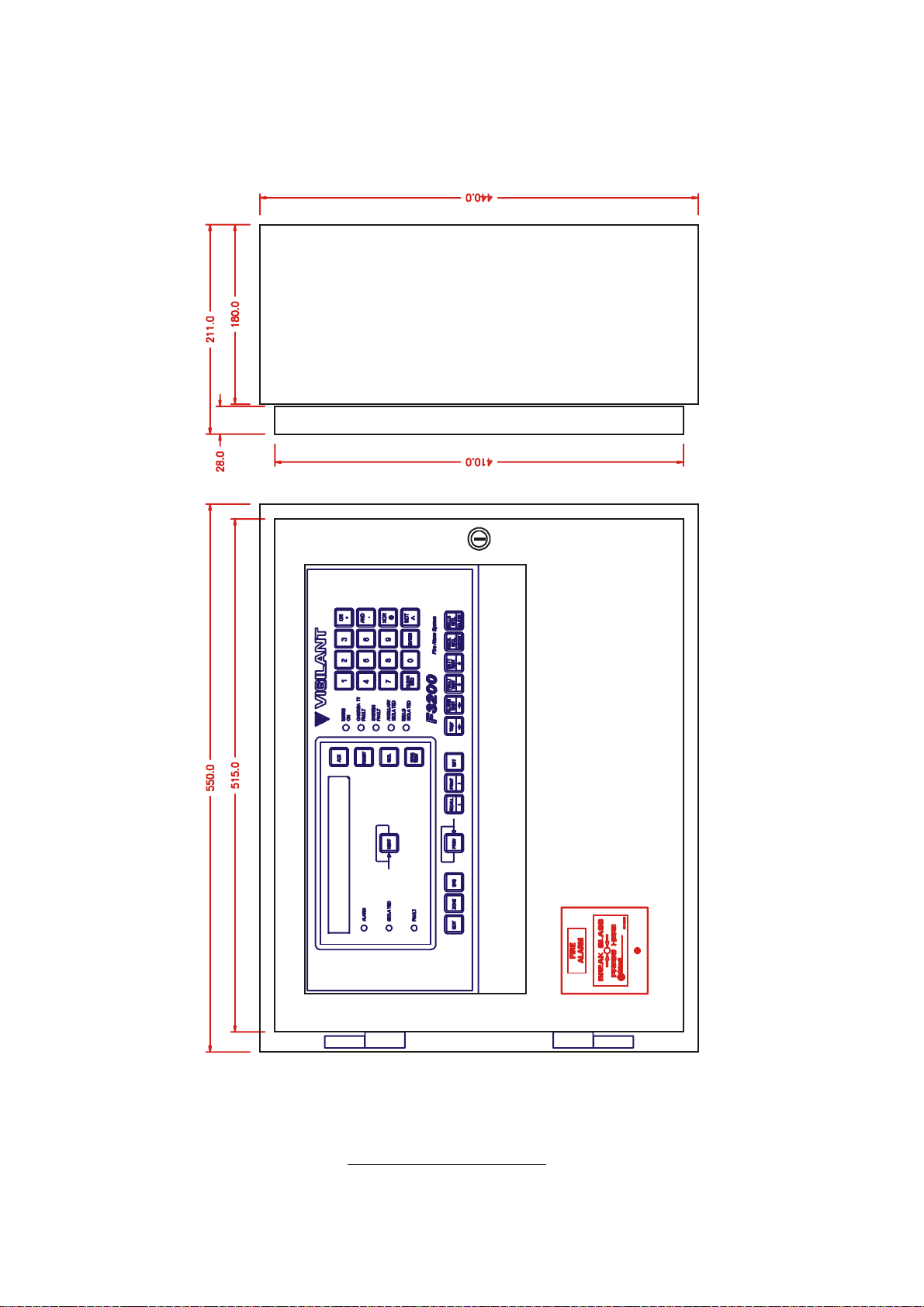
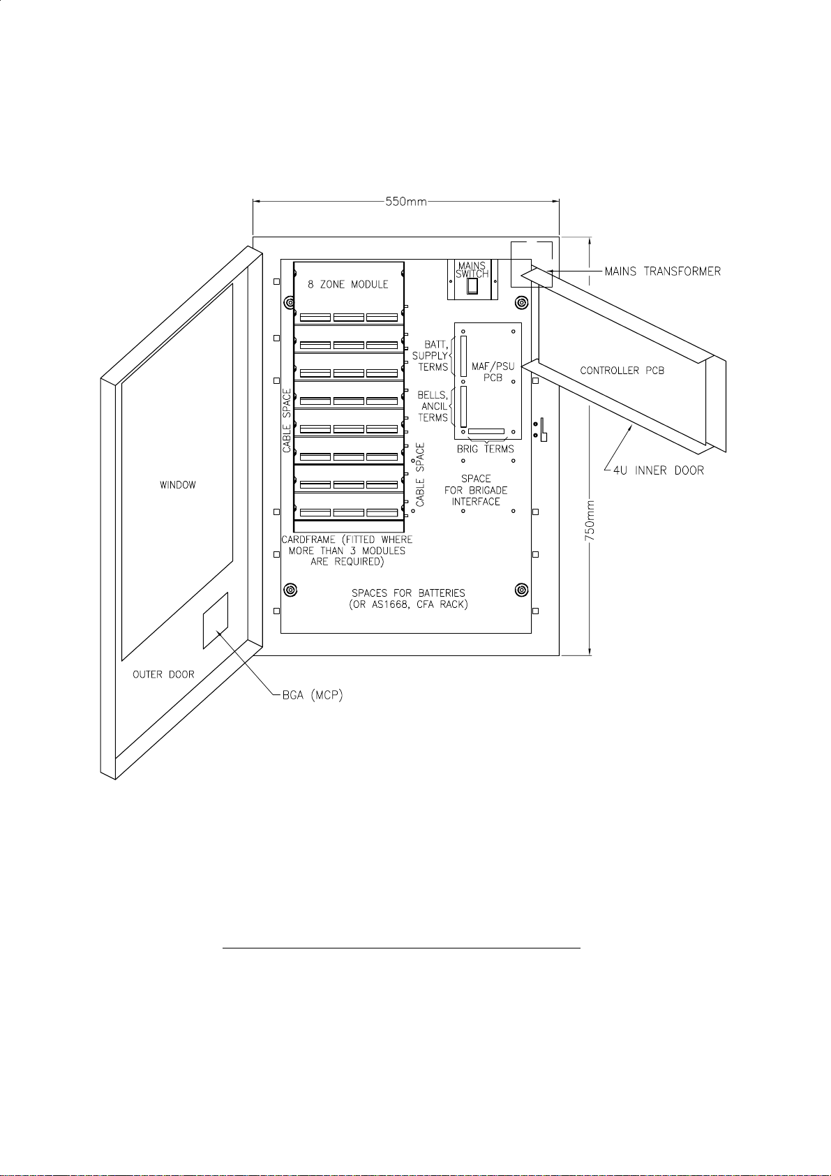
2.2 PHYSICAL STRUCTURE
The F3200 has a rugged, lockable painted steel cabinet, which houses 19 inch rack-mount
equipment and comes in two height options (both have the same width and depth). The
standard cabinet accommodates 15U total and the small cabinet accommodates 8U (where
1U = 1 3/4" = 44.5mm).
The Operator Display has a screened, polyester overlay mounted on a hinged inner door
fitted to the top 4U position. The Controller/Display pcb mounts directly to the rear of this
door.
Standard Cabinet
In the standard cabinet the space below the 4U Operator Display panel is covered by a
blanking plate, but there is provision for mounting other equipment (e.g. a 7U hinged inner
door for a mimic, or 16 Zone LED Display Bds), in place of this blanking plate.
There is provision for mounting additional equipment in the bottom 4U (e.g. an AS1668
control rack), but this would encroach on battery space.
The outer door has a large acrylic window to allow viewing of the equipment inside.
Four versions of FIP are available in this cabinet. The FP0551, which caters for up to 64
zones, has a cardframe fitted to the rear wall as shown in Fig 2.2.1. The FP0550 has
provision (pcb stand-offs) for mounting up to three 8 way modules (i.e. 3 x 8 Zone or 8 Relay
Modules) on the rear wall. Both are supplied with 1 8 Zone Module fitted.
Versions of these two FIPs are also available with a 6 Amp power supply:
FP0713 (8 module capacity), and FP0712 (3 module capacity).
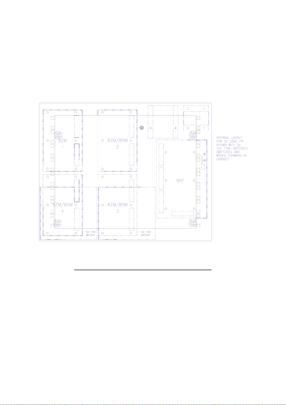
Small Cabinet
In the small cabinet, only 1U (of the 4U) below the 4U Operator Display is visible through the
outer window. The gap is covered by a blanking plate (2U), which can be replaced by a
bracket for mounting a limited range of equipment, eg. a 1U AIU bracket, or a 1U 1 Zone
Gas Control Panel.
A 6A PSU or a 7U LED Display door cannot be fitted.
Up to four 8 way modules can be mounted on the rear wall, but the bottom two of these
share space with the batteries. Mounting arrangement and maximum capacity are shown in
Fig 2.2.2.
Only one FIP is available (FP0583), and this comes with one 8 Zone Module fitted (in the top
left position).
Issue 2.7 5 July 2001 Page 2-7
Page 22
F3200 Installation & Programming Manual Document No: LT0122
System Description
Note: FP0551 and FP0713 have the cardframe as shown.
FP0550 and FP0712 have the modules (3 max.) mounted on the rear wall.
FIG 2.2.1
F3200 STANDARD CABINET - INTERNAL LAYOUT
Page 2-8 5 July 2001 Issue 2.7
Page 23
Document No: LT0122 F3200 Installation & Programming Manual
System Description
FIG 2.2.2
F3200, SMALL CABINET, MAXIMUM CONFIGURATIONS
Issue 2.7 5 July 2001 Page 2-9
Page 24

F3200 Installation & Programming Manual Document No: LT0122
System Description
2.3 SYSTEM STRUCTURE
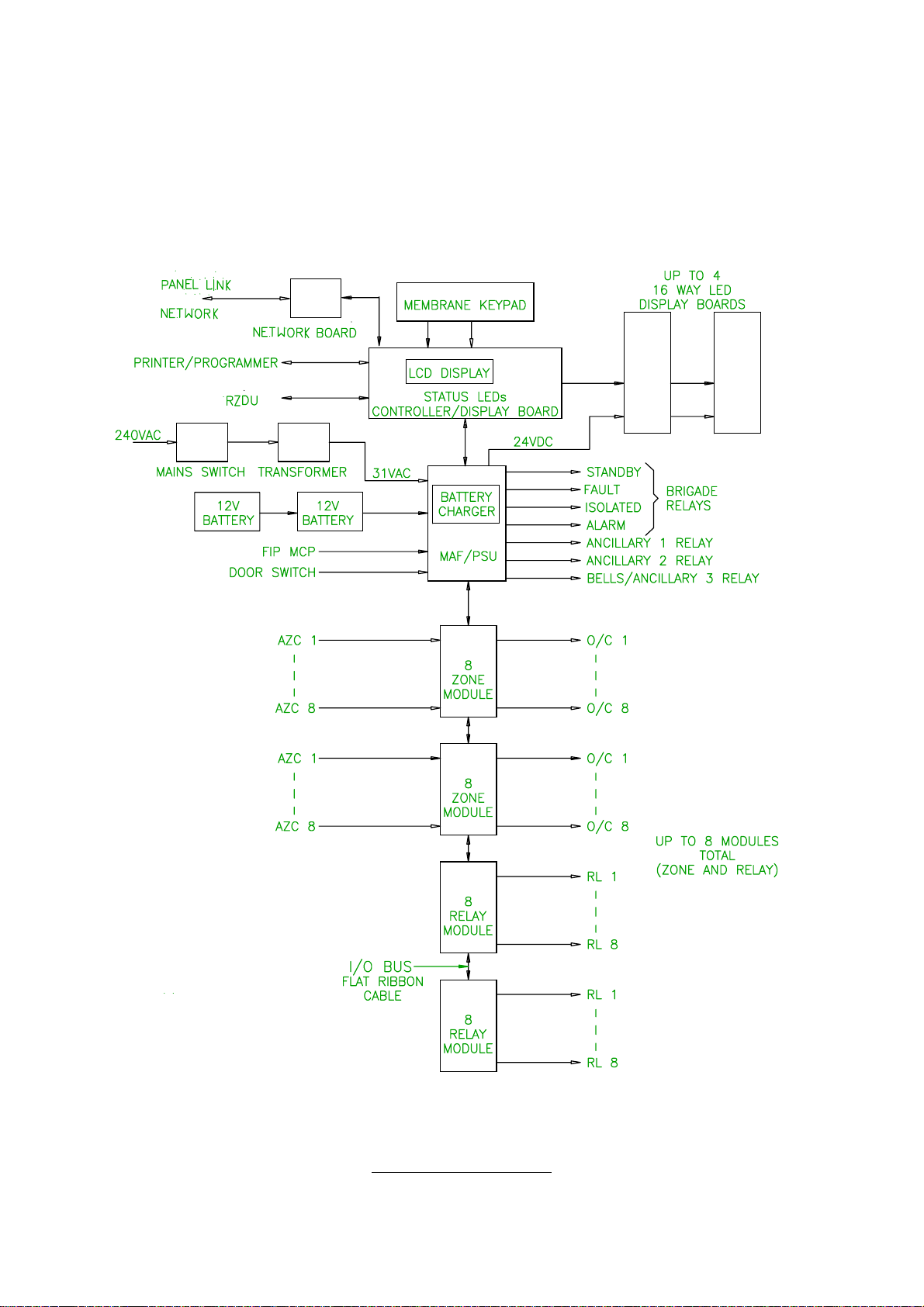
2.3.1 PCB MODULES
The 6 printed circuit boards which are used in an F3200 are as follows:
Controller/Display
Mounts on 4U inner door.
Includes: LCD, status LEDs and buzzer
keypad connection
5Vdc supply
voltage monitors for battery charger
microprocessor & memory
serial I/O bus control for all other modules
reference voltage generation for I/O modules
UARTs and serial port electronics
real time clock calendar integrated circuit
FRC connection to other modules.
MAF/PSU
Mounts on cabinet rear wall.
Includes: battery charger/PSU
22V regulator for detector circuits
Brigade & Ancillary relays and supervision circuitry
MCP & door switch inputs
screw terminals (most demountable) for field wiring
FRC connection to other modules.
8 Zone Module
Mounts on cabinet rear or in cardframe.
Includes: electronics to I/F to 8 Alarm Zone Circuits (AZCs)
8 open collector auxiliary outputs
demountable screw terminals for field wiring
FRC connection to other modules.
8 Relay Module
Mounts on cabinet rear or in cardframe.
Includes: 8 relays and supervision circuitry
demountable screw terminals for field wiring
FRC connection to other modules.
16 Zone LED Display
Mounts on 7U inner door.
Includes: 16 sets of 3 LEDs
electronics to control the LEDs (serial bus)
Page 2-10 5 July 2001 Issue 2.7
Page 25
Document No: LT0122 F3200 Installation & Programming Manual
System Description
RS485 "Panel-Link" Network Board
Connects to the Controller/Display Board
Includes: RS485 Board used for connection to the Vigilant Network.
FIG 2.3.1
SYSTEM STRUCTURE
Issue 2.7 5 July 2001 Page 2-11
Page 26

F3200 Installation & Programming Manual Document No: LT0122
System Description
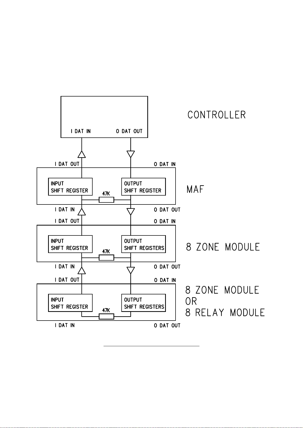
2.3.2 INTER-CONNECTION & STRUCTURE
A basic F3200 system
all connected by Flat Ribbon Cable (FRC) on a common Input/Output (I/O) Bus.
Additional 8 Zone Modules and/or 8 Relay Modules
maximum of eight 8 way modules. This is shown in the block diagram of Fig 2.3.1.
The physical maximums are:
three 8 way modules in an FP0550 or FP0712.
four 8 way modules in an FP0583 (with restrictions)
eight 8 way modules in an FP0551 or FP0713.
Expansion is from top to bottom.
The I/O Bus Out of one module connects to the I/O Bus In of the next module via the 20 way
FRC provided (LM0053).
No link or "End of Bus" is required on the last module because the data from the furthest
output shift register is fed into the furthest input shift register via the wrap-around resistor as
shown in Fig 2.3.2.
Refer to Section 3.1.3 Specifications for detail on the structural arrangement of AZCs and
relays.
To further extend these capabilities, up to 64 F3200s may be networked together, with full
sharing of information and remote control of each panel by a master panel.
has one Controller/Display, one MAF/PSU, and one 8 Zone Module,
can be fitted to the I/O bus, with a
16 Zone LED Display bds
They receive power from the MAF/PSU via two power leads. Where more than one is
required they are connected in series (up to 4 maximum) from right to left (as viewed from
the front) on the FIP. The 26 way FRC from J13 of the Controller goes to J1 ("From
Previous") of the right hand Display Bd. Zone 1 (default) corresponds to the top LEDs on
the left hand Display Bd. The last board requires the "end of bus" minijump connector to be
fitted. Note that a special FRC cable is required to connect the Controller Board to the first
Display Board (LM0092).
Where LED Display bds are fitted, the default programming requires one Display bd (16
zones) for every two 8 Zone Modules, i.e. one for 1-16 zones, two for 17-32 zones, etc.
Zone 1 corresponds to the top row of 3 LEDs on the left most Display. Zone 2 to the row
below it, etc, (top to bottom, left to right).
LED Display bds may also annunciate relay status, i.e. Alarm <-> relay energised, Isolated
<-> relay isolated, Fault <-> relay wiring fault (i.e. supervision fault).
The default programming for displaying both zone and relay status requires one Display bd
for every two 8 way modules (zone and relay).
are driven from a separate serial bus on the Controller/Display.
Page 2-12 5 July 2001 Issue 2.7
Page 27
Document No: LT0122 F3200 Installation & Programming Manual
System Description
INTER-CONNECTION & STRUCTURE (CONTINUED)
The relay LEDs simply follow the zone LEDs in the same order that they occur in the
modules. E.g. a system with three 8 Zone Modules and two 8 Relay Modules would require
3 Display bds. Relay 1 would be annunciated on the 25th row of LEDs and the last 8 rows
would be unused as shown in Fig 2.3.3.
Mapping zones and relays to LEDs in other patterns is programmable.
FIG 2.3.2
SERIAL DATA FLOW IN THE I/O BUS
Issue 2.7 5 July 2001 Page 2-13
Page 28

F3200 Installation & Programming Manual Document No: LT0122
System Description
Zone Module
1 1 ........1 1
8 8 8
9 1 9
16 8 ........16 16
17 1 ........1 17
24 8 24
1 1 25
8 8....16 32
1 9....1 33
8 16.... 40
8ZM 1
8ZM 2
8ZM 3
8RM 1
8RM 2
Relay Display
1
2
3
LAST 8 UNUSED 16
FIG 2.3.3
DISPLAY STRUCTURE
(DEFAULT MAPPING)
EXAMPLE FOR SYSTEM WITH 3 8ZM & 2 8RM
The F3200 can be configured to have a lesser number of Display Bds than required by the
default structure, with selective mapping of zones/relays to Display LEDs.
Page 2-14 5 July 2001 Issue 2.7
Page 29

Document No: LT0122 F3200 Installation & Programming Manual
System Specifications
CHAPTER 3
SYSTEM SPECIFICATIONS
Issue 2.7 5 July 2001 Page 3-1
Page 30

F3200 Installation & Programming Manual Document No: LT0122
System Specifications
3.1 GENERAL
3.1.1 FIP PART NUMBER & DESCRIPTION
Refer to Section 4 also.
FP0550, F3200 FIP, NO CARDFRAME, 24 ZONE MAX, 1931-15
Includes: Full size cabinet (ie. standard cabinet)
Controller/Display with FFCIF LCD & Keypad
MAF/PSU (includes 7 relays, 3A PSU)
1 x 8 Zone Module with standard EOLRs
Modules fit to cabinet rear wall (up to 3 modules max)
FP0551, F3200 FIP, C/W CARDFRAME, 64 ZONE MAX, 1931-16
Includes: Full size cabinet (ie. standard cabinet)
Controller/Display with FFCIF LCD & Keypad
MAF/PSU (includes 7 relays, 3A PSU)
Cardframe (can house up to 8 modules)
1 x 8 Zone Module fitted in cardframe
includes standard EOLRs
FP0583, F3200 FIP, SMALL CABINET
Includes: Small cabinet
Controller/Display with FFCIF LCD & Keypad
MAF/PSU (includes 7 relays, 3A PSU)
1 x 8 Zone Module with standard EOLRs
Modules fit to cabinet rear wall (up to 4 modules max)
FP0712, F3200 FIP, NO CARDFRAME, 24 ZONE MAX, C/W 6 AMP PSU
Includes: Full size cabinet (ie. standard cabinet)
Controller/Display with FFCIF LCD & Keypad
MAF/PSU (includes 7 relays, 6A PSU)
1 x 8 Zone Module with standard EOLRs
Modules fit to cabinet rear wall (up to 3 modules max)
FP0713, F3200 FIP, 64 ZONE MAX, C/W 6 AMP PSU
Includes: Full size cabinet (ie. standard cabinet)
Controller/Display with FFCIF LCD & Keypad
MAF/PSU (includes 7 relays, 6A PSU)
Cardframe (can house up to 8 modules)
1 x 8 Zone Module fitted in cardframe
includes standard EOLRs
3.1.2 SYSTEM EXPANSION
Expansion to the base panels is by adding 8 way zone input or relay output modules, or by
networking multiple panels together.
FP0553, F3200 8 ZONE INPUT EXPANSION KIT
Includes: 8 Zone Module, FRC, 8 x EOLR (std)
FP0554, F3200 8 RELAY EXPANSION KIT
Includes: 8 Relay Module, FRC, 8 x Minijump links (for supervision selection)
Page 3-2 5 July 2001 Issue 2.7
Page 31

Document No: LT0122 F3200 Installation & Programming Manual
System Specifications
3.1.3 ENVIRONMENTAL
Operating Temperature : -5°C to 45°C (Ambient)
Relative Humidity : 95% maximum @ 40°C (non-condensing)
3.2 MECHANICAL SPECIFICATIONS
CABINETS
Style : Wall mounting
Hinged outer door with large window (hinges to left)
Accepts 19" rack mounting equipment
4U Display on hinged inner door (hinges to right)
Construction : Welded steel
Material : 1.2mm and 1.6mm mild steel
Size :
- Standard : 750mm (H) x 550mm (W) x 210mm (D) * (Iss B cabinet)
- Small : 410mm (H) x 550mm (W) x 210mm (D) *
* MCP is an additional 20mm.
Finish : Powdercoat BFF-998-CW
Cream Wrinkle
(Iron Phosphate pre-treat)
Weight : Unpackaged Packaged
FP0550 20kg 22kg
FP0551 22kg 24kg
FP0583 17kg 19kg
FP0712 22kg 24kg
FP0713 24kg 26kg
Issue 2.7 5 July 2001 Page 3-3
Page 32

F3200 Installation & Programming Manual Document No: LT0122
System Specifications
3.3 ELECTRICAL SPECIFICATIONS
3.3.1 MAINS SUPPLY
Voltage : 240Vac +6% -10%
Current : 0.5A
Frequency : 50Hz
Termination : For up to 2.5sq mm TPS
3 Way block with wire protectors
3.3.2 BATTERY CHARGER & PSU
Input Voltage : 31Vac rms
(Transformer sec)
Charger Voltage : 27.3Vdc (nominal at 20°C)
Temperature : -36mV per °C nominal
Compensation
Non-Battery Backed : 28.0 nominal
Voltage
Max Total Current : 3Adc for std PSU (Charger, Quiescent & Alarm)
6Adc (for 6A PSU only)
Max Bell Current : 2Adc
Max. Ancillary : 2Adc
Current on VBF1
Max. Ancillary : 2Adc (allows 3A max LED Display)
Current on VBF2
Max. Ancillary : 2Adc (e.g. for door holders)
Current on VNBF
(VBF <-> battery backed, fused. VNBF <-> non-battery backed, fused)
Current Limit
Standard PSU 6A PSU
Battery to
MAF/PSU : PTC, 6A nom, 3.6A min (see notes below)
PSU/Charger : 3.3A nom, 3.0A min 6.7A nom, 6.0A min
Notes 1) : The 6A PSU is factory fitted in the FP0712 and FP0713. It is
not available in the FP0583.
2) : For the 6A PSU, the PTCs on the MAF are shorted out and a
Derwent 10A thermal cutout is wired between the battery +
terminal and the MAF/PSU.
Page 3-4 5 July 2001 Issue 2.7
Page 33

Document No: LT0122 F3200 Installation & Programming Manual
System Specifications
STATE MIN NOM MAX COMMENTS
Charger High 28.05 28.125 28.20 Adjust with pot
Charger Low 26.40 26.57 26.75
Battery Low 24.15 24.33 24.55
Standby Off 21.5 22.0 22.5 For voltage falling
Notes:
1. All voltages stated in VDC at temperature of 20°C.
2. Apply temperature compensation of -36 mV/°C for temperature deviation from 20°C.
3. This applies also to charger voltage 27.3 VDC.
4. There are thermal delays, therefore if checking or adjusting in field ensure unit has been
running for some hours.
5. Standby Relay is normally energised (on), and turns off for Battery fail.
TABLE 3.3.2
BATTERY AND CHARGER MONITORING VOLTAGE SPECIFICATIONS
3.3.3 BATTERY
Battery Voltage : 24Vdc nominal (2 x 12Vdc)
Compatible Makes Sonnenschein A200 & Sonnenschein A300 series
Powersonic PS12 series
Yuasa NP series
Capacity : 6 to 50 Ahr (dependent on configuration)
Space (mm) : - Standard Cabinet
Up to 220H, 440W, 175D (Iss B cabinet)
- Small Cabinet
Up to 200H, 185W, 175D (3 modules fitted)
Up to 200H, 370W, 125D (4 modules fitted)
(Refer to Fig 2.2.2)
Battery Test Load : 46 Ohm nominal. Suitable for 6 Ahr battery (with quiescent
current)
Provision for fitting extra resistors
NOTE: BATTERY TEST RESISTORS (R52, R53) MUST BE REMOVED FOR NEW
ZEALAN D OPERAT ION.
3.3.4 FUSES
Location : MAF/PSU PCB
Number Name
F1 +VBF1 5 x 20mm 2A Glass Cartridge, Std
F2 +VBF2 5 x 20mm 6A Glass Cartridge, Std
F3 +VNBF 5 x 20mm 2A Glass Cartridge, Std
F4 +VE 5 x 20mm 2A Glass Cartridge, Std
F5 Mains In 5 x 20mm 6A Glass Cartridge, Std
F7 +VBELLS 5 x 20mm 2A Glass Cartridge, Std
Size Rating Type
Issue 2.7 5 July 2001 Page 3-5
Page 34

F3200 Installation & Programming Manual Document No: LT0122
System Specifications
3.3.5 CURRENT CONSUMPTION
3.3.5.1 F3200 Quiescent & Alarm Currents
At 24Vdc battery supply, nominal currents:
Quiescent Alarm
FP0550, FP0551, FP0583, FP0712, FP0713 130mA 275mA
(notes 1-4)
8 Zone Module
- all AZCs disabled 4mA
- all AZCs enabled (notes 2-6) 82mA 97mA
Current per enabled AZC (note 3) 10mA
8 Relay Module
- all supervision disabled 4mA
- all supervision enabled 6mA
Current per relay on 11mA
MAF/PSU
- all relays off 9mA
Current per Ancillary Relay
(includes bells) 11mA 11mA
Current per Brigade Relay 16mA 16mA
(2 Zone)
22V Supply (supplies 8 Zones) max rating 800mA
Controller/Display
- LCD backlight off, status LEDs off 19mA
- LCD backlight on, status LEDs off 75mA
Current per status LED on 3mA
16 Zone LED Display 0mA 16mA/LED (steady)
RS485 network interface board PA0773 7.5mA
Total electronics and detector max rating 2000mA
Notes
1. FP0550/551/583/712/713 currents include Controller/Display, MAF/PSU and 1 x 8ZM
with all ACZs enabled and with EOLRs (2K7 for mode 1 or 2).
2. Quiescent current for an enabled AZC is for modes 1 or 2 (standard or high current)
and includes the 2k7 EOL, but not the detector current (up to 4mA detector current
per AZC).
3. Quiescent current is only 2.5mA per AZC for mode 3 and 1mA for mode 4.
4. Alarm current is for AZC mode 1, refer AZC specifications for other modes.
5. The 8 Zone Modules (8ZMs) are supplied from the fused battery supply via the 22V
regulator which has a maximum rating. The 8 Relay Modules (8RMs) are supplied
directly from the fused battery supply.
6. Quiescent and alarm currents do not include external loads e.g. door holders, bells,
etc.
Page 3-6 5 July 2001 Issue 2.7
Page 35

Document No: LT0122 F3200 Installation & Programming Manual
System Specifications
3.3.5.2 NDU Quiescent and Alarm Currents
4
Slimline NDU (FP0714/FP0773/FP0774
)
Operating Voltage : 24Vdc (18-28V)
Termination : For up to 2.5sqmm TPS
Quiescent Alarm
Current Consumption : 25mA 80mA
Full cabinet NDU (FP0715)
Quiescent Alarm
70mA 165mA
85mA 150mA
Current Consumption (Aust mode)
Current Consumption (NZ mode)
1
2
1. Includes controller, MAF/PSU, energised standby relay, PA0773 RS485 Bd, LCD
backlight off in quiescent state.
2. Includes controller, MAF/PSU, NZ Display Extender, energised standby and alarm
relays, PA0773 RS485 Bd. LCD backlight off in quiescent state.
3. Refer to Section 3.3.5.1 for additional module currents.
4. For FP0774 the I-Hub currents must be added.
Issue 2.7 5 July 2001 Page 3-7
Page 36

F3200 Installation & Programming Manual Document No: LT0122
System Specifications
3.4 INPUT SPECIFICATIONS
3.4.1 AZC SPECIFICATIONS
General
Terminations On 8 Zone Module, 2 per AZC.
Demountable screw terminal 1.5sq mm cable max.
Number 8 AZCs per 8 Zone Module.
64 max per system.
End of Lines (EOLs)
Mode EOL
1 Standard 2k7, 5%, 400mW resistor
2 High Current 2k7, 5%, 400mW resistor
3 Low Current 10k, 5%, 400mW resistor
4 Tamper EOL002B active EOL
5 Disabled None
Circuit Resistance & Capacitance
Mode Capacitance Resistance
1, 2 & 4 500nF 50 Ohm max
3 1000nF 800 Ohm max for B2 Alarm
2k Ohm max for B3 Alarm
Voltages
Min Typ Max
Detector Supply on MAF/PSU (note 1) 21.2V 22.0V 22.2V
(21.8V)
at AZC terminals 18.75V 20.3V 22.1V
at end of circuit 18.0V 20.3V 22.1V
Alarm Voltage Thresholds
Band B3 upper threshold 17.2V 17.5V 17.8V
Band B3 lower threshold 12.75V 13.1V 13.45V
Band B2 upper threshold
Band B2 lower threshold 2.7V 2.9V 3.1V
Band B1 upper threshold
Band B1 lower threshold 0V 0V 0V
Page 3-8 5 July 2001 Issue 2.7
Page 37

Document No: LT0122 F3200 Installation & Programming Manual
System Specifications
AZC SPECIFICATIONS (CONTINUED)
Min Typ Max
AZC current limit (note 1) 13.5mA 15.5mA 16.5mA
(14.5mA)
EOL & detector quiescent 11.95mA
EOL, no detectors 7.0mA 7.8mA 8.2mA
(7.2mA)
Fault threshold 4.4mA 5.75mA 6.8mA
Detector quiescent 0mA 4.0mA
Notes
1. The minimum figures shown are for battery voltage greater than the minimum
Standby (Battery Fail) level i.e. 21.5V. The figures shown in brackets are for a
battery voltage greater than 22.5V.
2. Modes 1 & 2 have the same thresholds before the Alarm state is latched. For Mode
2 additional current is turned on once the Alarm state is latched (refer to Graph
3.4.2).
Min Typ Max
Mode 3 Only
Current into short circuit 34.3mA
Current into 800 Ohm (note 3) 14.2mA 14.8mA 15.3mA
Current into 2000 Ohm (note 4) 8.0mA 8.2mA 8.4mA
EOLR Current 2mA
Minimum current for EOLR & 2k circuit 1.64mA
Modes 3 & 4
Fault thresholds 0.85mA 1.28mA 1.59mA
Maximum allowable load or circuit leakage 0.5mA
Notes
3. I.e. short at end of an 800 Ohm circuit (gives voltage band B2 alarm, ref graph 3.4.1).
4. I.e. short at end of a 2000 ohm circuit (gives voltage band B3 alarm, ref graph 3.4.1).
MCP Zener Diode
For voltage band B3 operation BZT03C15 3W, 15V.
Issue 2.7 5 July 2001 Page 3-9
Page 38

F3200 Installation & Programming Manual Document No: LT0122
System Specifications
AZC SPECIFICATIONS (CONTINUED)
Detector Alarm Currents
The current available to a latched detector is the AZC supply current at the detector "Alarm"
voltage minus the EOLR current and the remaining quiescent current at that voltage.
The following graphs show current/voltage characteristics for the various modes of
operation.
GRAPH 3.4.1
AZC CURRENT LIMIT CHARACTERISTICS (MODES 1 & 2)
ICL = Current Limit
IAV = Current Available to Detectors with EOLR fitted
IAV = ICL - IEOLR
GRAPH 3.4.2
AZC CURRENT VS VOLTAGE : MODE 1 (STANDARD)
Page 3-10 5 July 2001 Issue 2.7
Page 39

Document No: LT0122 F3200 Installation & Programming Manual
System Specifications
ICL+R = Current sourced through current limit and pull up resistor
IAV = Current available to detectors with EOLR fitted
IAV = ICL+R - IEOLR
GRAPH 3.4.3
AZC CURRENT VS VOLTAGE MODE 2 (HIGH CURRENT)
A short circuit at the end of an 800 Ohm line will give a B2 (Detector Operated) alarm.
A short circuit at the end of a 2k Ohm line will give a B3 (programmable) condition.
GRAPH 3.4.4
ACZ CURRENT VS VOLTAGE MODES 3 & 4 (LOW CURRENT & TAMPER)
Issue 2.7 5 July 2001 Page 3-11
Page 40

F3200 Installation & Programming Manual Document No: LT0122
System Specifications
AZC SPECIFICATIONS (CONTINUED)
Timing
Standard Delay 2.3 sec (2.0 - 2.6 sec)
(into Alarm, Fault, Normal)
AZC Reset 5.3 sec (5.0 - 5.6 sec)
AZC Ignore Period 1 2 sec nom (plus std 2.3 sec delay)
(after Reset)
AZC Ignore Period 2 1 sec nom (plus std 2.3 sec delay)
(after Start Up or Programming)
AZC Time Into Alarm Programmable 0-250 sec
AZC Time Out of Alarm Programmable 0-250 sec
Refer to Section 7.2.4 for detail on other sequences and programmable delays.
3.4.2 MAF/PSU INPUTS
Battery Termination One pair screw terminals; 4sq mm max cable
AC Input 31V rms; 3.6A rms; 2.8mm tab terminals
Door Switch 5V, 0.5mA, Unsupervised, 4 Way .1" pcb header, J6
MCP 5V, 1mA, 2k7 EOLR, 4 Way .1" pcb header, J6
Spare Inputs (not fitted) 5V, 0.5mA, Unsupervised, Cabinet internal use only, 4 Way
.1" pcb header, J5
Relay Supervision
Anc 1 Sup/Anc 2 Sup One screw terminal each
Modes of Operation 1 Door holder (Default for Anc 1)
2 Load (Default for Anc 2)
Relay Off Relay On
Door Holder Mode expects Voltage Present No Voltage Present
Load mode expects Resistive to 0V Open Circuit or Voltage Present
Voltage Threshold 3.65V Nom
(Door Holder Mode)
Supervision Current 0mA @ +5V, 1mA @ 0V
Load Resistance 400 Ohm - 10k Ohm
(Load Mode) less than 400 Ohm with series diode at load.
14 Ohm absolute minimum.
Bells Relay
Form Reverse polarity - requires series diode at each device
Page 3-12 5 July 2001 Issue 2.7
Page 41

Document No: LT0122 F3200 Installation & Programming Manual
System Specifications
MAF/PSU INPUTS (CONTINUED)
End of Line Resistor No. of Circuits Type
1 3k3, 5%, 250mW resistor
2 6k8, 5%, 250mW resistor
3 10k, 5%, 250mW resistor
Supervision Current 0mA @ +5V, 1.5mA @ 0V, +ve to BELLS- terminal
Circuit Resistance 100 Ohm max.
3.4.3 CONTROLLER/DISPLAY INPUTS
Spare DC Input/Output 24Vdc nom demountable screw terminal, 4 way, J5
Spare Input 22V, 10k Ohm pull up resistor
Provision for supervision (up to 5 band)
Spare Inputs IP0, 1, 2 Unsupervised, Cabinet internal use only
(not fitted) +5V, 100k pull up resistor, 10 Way FRC header, J10
Serial I/O RZDU Refer Section 3.5.3; Others 3.5.2
3.4.4 8 RELAY MODULE SUPERVISION
Form Load monitoring
Relay Off Relay On
Expects Resistance to 0V Voltage Present
Selected By Minijump link on pcb & programming of FIP
Default Programming Disabled (unsupervised)
Load Resistance 400 Ohm - 10k Ohm
Less than 400 Ohm with series diode at load
14 Ohm absolute minimum
Voltage Threshold 3.65V nom.
Supervision Current 0mA @ +5V, 1mA @ 0V
3.4.5 NZ MODE DISPLAY EXTENDER BOARD INPUTS
The Display Extender Board is used with New Zealand operation only. The inputs it
provides are : Silence Alarms, Trial Evac, Building Services Restore, Lamp Test and
External Defect. All inputs have closure to zero volts to assert the input. An input may be
left open or unconnected if not used. Refer to section 12.8 for wiring.
All Inputs Closure below 1.5V @ 0.35mA required to activate.
Open voltage = 5V
Issue 2.7 5 July 2001 Page 3-13
Page 42

F3200 Installation & Programming Manual Document No: LT0122
System Specifications
3.5 OUTPUT SPECIFICATIONS
3.5.1 8 ZONE MODULE OUTPUTS
Type Darlington open collector
Switch to 0V
Voltage Rating 28.5V max, "off" state
1V max @ 30mA, "on" state
1.1V max at 100mA
Current Rating 100mA max per O/P, 0.6A max per module
1A max per FIP.
Transient Protection Allows external wiring
Terminations 8 Way demountable screw terminal
1.5sq mm max. cable
Operation Programmable
Default O/C 1 = Zone 1 Alarm
O/C 2 = Zone 2 Alarm
etc.
3.5.2 8 RELAY MODULE OUTPUTS
Form 1 Pole changeover contacts
Voltage-free when unsupervised
Termination Demountable screw terminals
1.5sq mm max cable
Rating ELV only
30V, 2Adc resistive
30V, 1Adc inductive
Note The relays are 2 pole, with the second pole terminated on pcb pads.
Operation Programmable
Supervision Ref 3.4.4.
Looping Terminals 2 Sets of 4 joined
voltage-free terminals per module
Page 3-14 5 July 2001 Issue 2.7
Page 43

Document No: LT0122 F3200 Installation & Programming Manual
System Specifications
3.5.3 MAF/PSU OUTPUTS
Brigade Relays
Number 4
Standby Normally energised
De-energises on battery fail or panel fail
Fault, Isolated, Alarm Normally de-energised
Energise on active state
Form 1 Pole changeover contacts
Voltage-free
Termination Demountable screw terminals
1.5sq mm max cable
Rating ELV only
30V, 5Adc resistive
30V, 3Adc inductive
Isolation 1500V rms contact to coil
Ancillary & Bells
Number 3
Anc 1, Anc 2
Termination Demountable screw terminals
Rating ELV only
(Note: The relays are 2 pole, with second pole terminated on pcb pads).
Operation Programmable
Default Active on any unisolated Zone Alarm.
Supervision Separate terminal (ref 3.4.2)
Anc 3/Bells
1 Pole changeover contacts
Voltage-free
1.5sq mm max cable
30V, 2Adc resistive
30V, 1Adc inductive
2 pole relay
Link selectable function
Standard Format Bells
Switched 24Vdc output
2 terminals, Bells +, Demountable screw terminals
1.5sq mm max cable
Issue 2.7 5 July 2001 Page 3-15
Page 44

F3200 Installation & Programming Manual Document No: LT0122
System Specifications
MAF/PSU OUTPUTS (CONTINUED)
Option 1 Pole changeover contacts
Voltage-free
Snip Links Lk2, 3, 4.
Rating ELV only
30V, 2Adc resistive
30V, 1Adc inductive
24V, 1.5Adc inductive bells
Operation Programmable
Default Active on any unisolated zone alarm
Supervision On Bells +, - only
(ref 3.4.2)
Power Supply Outputs
0Vdc
Termination 1 non-demountable screw terminal
4sq mm max cable
2 demountable screw terminals
1.5sq mm max cable
1 2.8mm tab terminal (LED Display)
Battery Backed DC Supply
Rating 27.3Vdc nom.
(24V battery nom)
2Adc, fused.
+VBF1
Termination 1 non-demountable screw terminal
4sq mm max cable
1 demountable screw terminal
1.5sq mm max cable
+VBF2
Termination 1 non-demountable screw terminal
4sq mm max cable
1 demountable screw terminal
1.5sq mm max cable
1 2.8mm tab terminal (LED Display)
Page 3-16 5 July 2001 Issue 2.7
Page 45

Document No: LT0122 F3200 Installation & Programming Manual
System Specifications
MAF/PSU OUTPUTS (CONTINUED)
Non-Battery Backed DC Supply
Rating 28Vdc nom
2Adc, fused
+VNBF
Termination 1 non-demountable screw terminal
4sq mm max cable
1 demountable screw terminal
1.5sq mm max cable
RZDU Comms
Tx, Rx, 0V 3 Wire (+VBF2 also available)
Transmission Rate 1200 Baud
Protocol Vigilant F4000
Termination Demountable screw terminals
1.5sq mm max cable
3.5.4 CONTROLLER/DISPLAY OUTPUTS
Spare Parallel Outputs
Number 6
Type CMOS
Voltage Rating 0-5V
Termination 10 Way FRC pcb header, J10
Serial I/O
Printer/Programmer Port
Form Pseudo RS232
Transient Protection Allows external wiring
(not fitted)
Rx, Tx, 0V signals only
Transmission Rate 9600 Baud
Protocol ASCII Xon, Xoff
Termination 4 Way .156" male molex (J1)
9 Way Miniature D available via transition cable
Part number LM0041
Female Pins (socket)
Issue 2.7 5 July 2001 Page 3-17
Page 46

F3200 Installation & Programming Manual Document No: LT0122
System Specifications
CONTROLLER/DISPLAY (CONTINUED)
Pin 2 3 5 1 4 6 7 8
Tx Rx 0V └──┴──┘ └──┘
25 Way Miniature D available via transition cable Part Number
LM0042
Female Pins (socket)
Pin 2 3 7 6 8 20
Rx Tx 0V └──┴──┘
Alternative Function (on same serial port)
Serial Port 0
Network 1
Network 2
3.5.5 RS485 BOARD
CMOS Modem: 10 Way FRC header
+12V, RXD- TXD-, RTS-, CTS-, 0V, DCD-, +5V
Network: 6 Way demountable screw terminals
RS485 standard signals
A+, A-, B+, B-, 0V ISOL, Earth
3.5.6 NZ DISPLAY EXTENDER BOARD OUTPUTS
10 Way FRC header, J2
UART signals: RXD, TXD, RTS-, CTS-, DCD5V levels; 0V, +5V, +24V also available
10 Way FRC header, J7
(fitted only for network systems)
10 Way FRC header, J9
(fitted only for network systems)
UART signals for Network 1/2
RXD, TXD, RTS-, CTS-, DCD5V levels; 0V, +5V, +24V also available
This is used in New Zealand mode only. Refer to section 12.8 for wiring of the outputs on
the unprotected termination board. The Display Extender Board already has common
Normal, Defect and Fire status LEDs fitted to it, but these may be replicated externally if
necessary. There are also ancillary defect and fire outputs which are active low open
collector, and an output to drive an index lamp.
All Outputs (except LAMP) Open collector pulldown to 0V
Off voltage = 30Vmax
On voltage = 1.1V @ 100mA (max)
On Current = 100mA max
LAMP + Open collector pull up to VBATT
Off voltage = 0V
On voltage = VBATT-1V
On current = 400mA max
LAMP - Connected to Battery –
Page 3-18 5 July 2001 Issue 2.7
Page 47

Document No: LT0122 F3200 Installation & Programming Manual
System Specifications
3.6 CONTROLS
KEYPAD
Type : Polyester Membrane
Keypress : Buzzer gives short "beep" for valid keypress
Number of
Keys : 34 (plus 5 concealed with no function)
FFCIF Keys : ACK; RESET; ISOL; BRIG TEST
Other Keys : Ref F3200 Operator's Manual for description
INTERNAL CONTROLS
Mains On : Switch in cabinet
Database Write Protect
Function : Enables/disables writing to EEPROM
Form : 2 position minijump shunt, Lk7
On Controller/Display PCB
E2 INIT
Function : Initiates self-programming of system configuration on system power
up (i.e. number of modules, etc)
Requires DATABASE WRITE PROTECT to be in WRITE position.
Form : 2 Way .1" male pins on Controller/Display PCB
Short circuit pins to initiate.
BUZZER
Mounted on Controller/Display pcb
Type : Piezo Electric
Frequency : 2800Hz nominal
Sound Level : 70dB min at 1m (outer door closed)
Issue 2.7 5 July 2001 Page 3-19
Page 48

F3200 Installation & Programming Manual Document No: LT0122
System Specifications
3.7 DISPLAYS
Standard Display
Includes : LCD; FFCIF LEDs; System Status LEDs
Panel Size : 19", 4U
FFCIF Type : 3 (common indicators & common controls)
Standard : Complies with AS4050 (int) - 1992
LCD Size : 2 Lines of 40 characters
5.5mm (H) x 3.2mm (W) per character
Site Name : 40 Characters max.
Zone Name : 30 Characters max.
Relay Name : 30 Characters max.
FFCIF LEDs : ALARM (red); ISOLATED (yellow); FAULT (yellow)
System
Status LEDs : MAINS ON (green); CHGR/BATT FAULT (yellow); SYSTEM FAULT
(yellow); ANCILLARY ISOLATED (yellow); BELLS ISOLATED (yellow)
Internal : Mains On (green), Fuse Blown (yellow) on MAF/PSU pcb.
Status
LEDs
Optional Additional Display
Requires 1 x ME0060 plus: 1 x FZ3031 plus 1-3 FP0475 as required.
Note: FZ3031 contains the FRC cable (LM0092) that is
required to connect the Controller Board to the first
Display Board.
ME0060, MECH ASSY, 1901-79, F4000 RAC, EXT INNER DOOR
(19", 7U, mounts up to 4 of 16 Zone LED Display Bd)
FP0475, FP, 16 ZONE LED DISPLAY EXTENDER KIT, 1901-26
Includes : 1 x 16 Zone LED Display Bd; FRC; Power leads; zone name label
(FP0475 has 0.5m FRC, FZ3031 has 1.2m FRC).
Format : 7U Parallel LED display mounts directly below the standard 4U LCD.
The LCD and common LEDs operate as per standard. Zone status is
additionally shown on the zone LEDs.
FFCIF Type : 2 (individual zone indicators and common controls)
Zone LEDs : ALARM (red); FAULT (yellow); ISOLATED (yellow)
Name Space : 10mm x 60mm per zone on paper label.
E.g. 2 lines of 23 characters at 10 per inch.
Page 3-20 5 July 2001 Issue 2.7
Page 49

Document No: LT0122 F3200 Installation & Programming Manual
Ordering Information
CHAPTER 4
ORDERING INFORMATION
Issue 2.7 5 July 2001 Page 4-1
Page 50

F3200 Installation & Programming Manual Document No: LT0122
Ordering Information
4.1 ORDERING INFORMATION
The following lists the part numbers for the range of products and spares associated with the
AS1603.4 approved F3200. It includes a brief description where considered necessary.
FA1227,FAB,1931-24,F3200 BLANK PANEL,PLASTIC,9.5U
FA1235,FAB,1919-27-5,F3200,FLUSH SURROUND (P) (STD CABINET)
FA1298,FAB,1919-27-6,F3200,SMALL FLUSH SURROUND (P)
FA1299,FAB,1919-27-7,F3200,STD + BATT BOX,FLUSH SURROUND (P)
FA1300,FAB,1919-27-8,F3200,SMALL + BATT BOX,FLUSH SURROUND (P)
FP0475,16 ZONE LED DISPLAY EXTENDER KIT,1901-26
(includes Display Bd, 0.5m FRC, power leads and label master. Cannot be used for first
LED Display. See FZ3031)
FP0550,F3200 FIP,NO CARDFRAME,24 ZONE MAX,1931-15
(ref Section 3.1.1)
FP0551,F3200 FIP,C/W CARDFRAME,64 ZONE MAX,1931-16
(ref Section 3.1.1)
FP0553,F3200 8 ZONE INPUT EXPANSION KIT
(ref Section 3.1.2)
FP0554,F3200 8 RELAY EXPANSION KIT
(ref Section 3.1.2)
FP0556,F3200 CABINET,EMPTY,C/W DOOR,WINDOW,LOCK
FP0557,F3200 CABINET,EMPTY,C/W BLANK OUTER DOOR
FP0558,F3200 REMOTE LCD DISPLAY UNIT, FULL CABINET & MAF/PSU
Similar to FP0550, but with RDU Controller and Software, No 8ZM. Previously called RZDU.
Refer to manuals LT0133 and LT0148.
FP0559,F3200 REMOTE LCD,DISPLAY UNIT,SLIMLINE,WALL MOUNT
(small, low profile cabinet with F3200 RDU Controller fitted, no MAF or PSU)
FP0570,FP,1937-3-1,LOCAL GAS CONTROL STATION,AUTO
(wall mounting box with flip cover break glass "Gas Start" switch and double action toggle
"Gas Inhibit" switch, includes buzzer and LEDs)
FP0572,FP,1937-3-2,LOCAL GAS CONTROL STATION,MANUAL
(as per above, but without "Gas Inhibit" switch, LED and buzzer)
FP0576,FP,F3200,BATTERY BOX
FP0577,FP,REMOTE LCD DISPLAY UNIT,4U 19" RAC UNIT
(Includes ME0064 plus I/F PCB, FRC, earth wire, RDU, Operator's Manual, door switch (c/w
bracket and loom) and MCP loom).
FP0583,FP,F3200 FIP,SMALL CABINET
FP0584,FP,F3200,SMALL EMPTY CABINET,FULL WINDOW
FP0585,FP,REMOTE LCD DISPLAY,SMALL CABINET,C/W MAF/PSU
Page 4-2 5 July 2001 Issue 2.7
Page 51

Document No: LT0122 F3200 Installation & Programming Manual
Ordering Information
ORDERING INFORMATION (CONTINUED)
FP0712,FP,F3200 FIP,NO CARDFRAME,24 ZONE MAX,6A PSU
FP0713,FP,F3200,FIP,64 ZONE MAX,6A PSU
FP0714,FP,NETWORK DISPLAY UNIT (NDU),SLIMLINE,WALL MOUNT
FP0715,FP,NETWORK DISPLAY UNIT (NDU),FULL CAB & MAF/PSU
FP0731,FP,RDU TO NDU UPGRADE KIT
FP0733,FP,NETWORK DISPLAY UNIT,4U 19" RACK MTG,NO MAF/PSU
FP0749,FP,F3200 6A PSU UPGRADE KIT,1931-44
Kit to purchase to upgrade on existing panel to a 6A PSU.
FP0772,FP,REMOTE LCD DISPLAY (RDU),SLIMLINE,FLUSH MOUNT
Same as FP0559 except is a flush mounting cabinet.
FP0773,FP,NETWORK DISPLAY UNIT (NDU),SLIMLINE,FLUSH MOUNT
Same as FP0714 except is a flush mounting cabinet.
FP0774,FP,NDU,NETWORK DISPLAY,C/W I-HUB,SLIMLINE,SURFACE
Surface mount NDU, contains I-Hub for networking.
FZ3010,F3200,16 ZONE,STD CAB,NO CARDFRAME,NO LED,1U SHELF
(FP0550 with second 8ZM and 1U document shelf fitted)
FZ3024,F3200,8 ZONE,NO CARDFRAME,NO LEDS,7U BLANK,1U SHELF
(FP0550 with 7U blank hinged door and 1U document shelf fitted)
FZ3027,F3200,64 ZONE,C/W LEDS,1U SHELF
FZ3031,KIT,F3200,16 ZONE LED DISPLAY,LHS POSITION
(as per FP0475, but with 1.2m FRC, allows mtg of Display Bd in furthest left position.
Required for first display).
FZ3034,F3200,8 ZONE,NO CARDFRAME,NO LEDS,6A PSU
FZ3051,F3200,1 ZONE GAS CONTROL,SMALL CABINET
FZ9002,FP,19" RAC,7U BLANK INNER DOOR
FZ9009,KIT,19" RAC,3U AIU BRKT (mounts 2 Melbourne F.B. AIUs)
FZ9010,KIT 19" RAC,1U AIU BRKT (mounts 2 Melbourne F.B. AIUs)
(These include bracket and screws, etc, The 1U item is 1U at the front, but larger at the rear,
as required for F3200 small cabinet).
KT0072,KIT,F3200,CARDFRAME UPGRADE
KT0075,KIT,F3200,PSU UPGRADE,3A TO 6A,1931-44 (Factory fitted option only)
KT0111 KIT,1945-1-1,AS1668 CONTROL MODULE,TYPE 1 (refer PBG0015)
KT0112 KIT,1945-1-2,AS1668 CONTROL MODULE,TYPE 2 (refer PBG0015)
KT0113 KIT,1945-1-3,AS1668 CONTROL MODULE,TYPE 3 (refer PBG0015)
LM0041,LOOM,1888-58,PROG PORT TO 9 PIN SERIAL
(cable to connect printer/computer to Controller, has 9 pin min D)
Issue 2.7 5 July 2001 Page 4-3
Page 52

F3200 Installation & Programming Manual Document No: LT0122
Ordering Information
ORDERING INFORMATION (CONTINUED)
LM0042,LOOM,1888-62,PROG PORT TO 25 PIN SERIAL
(cable to connect printer/computer to Controller, has 25 pin min D)
LM0044,LOOM,1901-81-1,DISPLAY EXTENDER FRC,2M
LM0045,LOOM,1901-81-2,DISPLAY EXTENDER FRC,5M
LM0046,LOOM,1901-81-3,DISPLAY EXTENDER FRC,0.5M
LM0049,LOOM,1901-81-4,DISPLAY EXTENDER FRC,0.25M
LM0053,LOOM,1931-28-1,F3200 20 WAY FRC,300MM
(standard FRC for interconnecting 8 way modules, included in FP0553, 554)
LM0092,LOOM 1901-88 CONTROLLER TO 1ST DISPLAY, FRC, 1.2M
(connects Display Bd to Controller, allows mounting of Display Bd in furthest left position,
included with FZ3031).
LT0119 LITERATURE,1931-17,F3200 OPERATOR'S MANUAL,A4,LOOSE
LT0120 LITERATURE,1931-18,F3200 OPERATOR'S MANUAL,A5
LT0121 LITERATURE,1931-19,F3200 TECHNICAL MANUAL
LT0122 LITERATURE,1931-20,F3200 PROGRAMMING & INSTALLATION MANUAL
LT0130 LITERATURE,1931-32,F3200 PRESENTATION,ACAD12 DISK
LT0133 LITERATURE,1931-46,REMOTE LCD UNIT,OPERATOR MANUAL,A4
LT0135 LITERATURE,1931-52,F3200 ARCHITECTS SPEC,A4
LT0148 LITERATURE,1931-64,RDU INSTALLATION & PROGRAM MANUAL
LT0212 LITERATURE,RDU TO NDU UPGRADE INSTRUCTIONS
ME0060,MECH ASSY,1901-79,RAC CABINET,EXT INNER DOOR
(hinged 7U inner door for mounting Display Bds on, includes screws, perspex window, cage
nuts and pcb standoffs)
ME0063,MECH ASSY,1931-15-1,F3200 4U HINGED CONTROL PANEL
(4U hinged door with keypad and Controller/Display pcb mounted on it).
ME0064,MECH ASSY,1931-15-1,F3200 4U HINGED RDU CONTROL PANEL
(4U hinged door with no-name keypad and RDU Controller/Display mounted on it).
ME0065,MECH ASSY,1931-47,1 ZONE GAS CONTROL 7U DOOR
ME0066,MECH ASSY,1931-47,2 ZONE GAS CONTROL 7U DOOR
ME0067,MECH ASSY,1931-47,3 ZONE GAS CONTROL 7U DOOR
ME0068,MECH ASSY,1931-47,4 ZONE GAS CONTROL 7U DOOR
(ME0065-68 include screened 7U door, field connector and looms for connecting to 8RMS
and 8ZMs, screws and cage nuts - for 1,2,3 or 4 gas zones)
Page 4-4 5 July 2001 Issue 2.7
Page 53

Document No: LT0122 F3200 Installation & Programming Manual
Ordering Information
ORDERING INFORMATION (CONTINUED)
ME0069,MECH ASSY,1931-57,1 ZONE, 1U GAS CONTROL PANEL
(similar to ME0065 except on a non-hinged, 1U panel)
ME0072,MECH ASSY,1931-70,F3200 RACK MTG GEARPLATE
(allows F3200 internals to be fitted to a RAC cabinet. Factory fit option only. See Note 1)
ME0155,MECH ASSY,694-384,19" 4U CFA ASSEMBLY
ME0250,MECH ASSY,1919-35,RAC CABINET,IP65,20U X 200 (ie. waterproof)
ME0258,MECH ASSY,1919-21-2,RAC CABINET,1U SHELF,135 DEEP
(includes screws and cage nuts for mounting to FIP)
PA0443,PCB ASSY,1841-18,CONTACT CONVERSION MODULE
PA0491,PCB ASSY,1931-3,F3200 MAF/PSU
PA0492,PCB ASSY,1931-4,F3200 8 ZONE MODULE (See FP0553)
PA0493,PCB ASSY,1931-5,F3200 RZDU CONTROLLER/DISPLAY (See FP0554)
PA0703,PCB ASSY,1931-27,F3200 REMOTE I/F BD
PA0707,PCB ASSY,1931-39,F3200 3A RECTIFIER BD
PA0773,PCB ASSY,1901-139-3,RS485 COMMS BD,CMOS;FRC ONLY
PA0797,PCB ASSY,1931-84-1,F3200 CONTROLLER/DISPLAY
PA0798,PCB ASSY,1931-84-2,F3200 RDU CONTROLLER/DISPLAY
PA0804,PCB ASSY,1931-84-1,F3200 CTRL NETWORK/NDU,NO S/W
RR0509,RESISTOR,WIRE WOUND,10W,68 OHM
SF0089,SOFTWARE,F3200 FIRE CONTROLLER,V1.10 EPROM
SF0094,SOFTWARE,REMOTE LCD DISPLAY,RDU,V1.35 EPROM
SF0164,SOFTWARE,F3200 FIRE CONTROLLER NETWORKED,V2.04,EPROM
SF0175,SOFTWARE,NETWORK DISPLAY UNIT (NDU),V2.04,EPROM
SF0178,SOFTWARE,F3200 FIRE CONTROLLER,V2.04,EPROM
SF0179,SOFTWARE,REMOTE LCD DISPLAY,RDU,V2.02 EPROM
SF0229,SOFTWARE,F3200,STD PANEL,C/W TANDEM,V2.09 EPROM
SF0230,SOFTWARE,F3200,NETWORKED,C/W TANDEM,V2.09,EPROM
SF0231,SOFTWARE,NDU,C/W TANDEM,V2.09,EPROM
Issue 2.7 5 July 2001 Page 4-5
Page 54

F3200 Installation & Programming Manual Document No: LT0122
Ordering Information
ORDERING INFORMATION (CONTINUED)
NEW ZEALAND OPERATION ONLY
A variety of display options are available to satisfy varying NZ requirements. These are
covered in detail in Section 12.8. Ordering codes are included for the various components
for each option. Major items are as follows:
PA0499 PCB ASSY, NZ DISPLAY EXTENDER BOARD
NZ Display Extender Board in standard 16 Zone LED board format.
PA0742 PCB ASSY, PFD NZ DISPLAY EXTENDER BOARD, 24V
NZ Display Extender Board in format suitable for “picture frame” cabinet.
PA0741 PCB ASSY, PFD 16 ALARM LED DISPLAY, 24V
“Picture Frame” format 16 Zone display board (alarm LEDs only).
PA0754 PCB ASSY, PFD 16 ZONE FULL STATUS, 24V
“Picture Frame” format 16 Zone display board (all LEDs fitted).
PA0753 PCB ASSY, PICTURE FRAME DISPLAY, 16 LED MIMIC, 24V
“Picture Frame” cabinet format board for mimicking 16 Fire LEDs from Display
board.
PA0760 PCB ASSY, NZ DISPLAY EXTENDER, PFD MIMIC
“Picture Frame” cabinet format board for mimicking 3 LEDs from Display
Extender Board.
PA0483 PCB, UNPROTECTED TERMINATION BOARD
With a 26 way FRC gives access Display Extender Board inputs and outputs.
PA0772 PCB ASSEMBLY, PFD TERMINATION BOARD
Breaks 26-way display FRC out to multicore cable (12 way).
PA0769 PCB, UNPROTECTED TERMINATION BOARD, C/W RESISTORS
Versions of PA0483 with 3k3 resistor per output for LED current limit.
ME0074 PICTURE FRAME DISPLAY, F/S NZ LOCK, C/W INDEX
Wall mounting “Picture frame” display cabinet.
ME0076 PICTURE FRAME DISPLAY, R/S NZ LOCK, C/W INDEX
Window mounting, “Picture frame” display cabinet.
ME0073 PICTURE FRAME DISPLAY, F/S 003 LOCK, C/W INDEX
Wall mounting “Picture frame” display cabinet with 003 lock.
Page 4-6 5 July 2001 Issue 2.7
Page 55

Document No: LT0122 F3200 Installation & Programming Manual
Configuring a FIP
CHAPTER 5
CONFIGURING A FIP
Issue 2.7 5 July 2001 Page 5-1
Page 56

F3200 Installation & Programming Manual Document No: LT0122
Configuring a FIP
5.1 GENERAL
An F3200 FIP is configured to suit a particular customer's requirements by:
Fitting and connecting the required pcb modules;
adding appropriate battery test resistors when necessary;
adjusting or removing links on the pcbs;
programming the FIP.
The detectors, manual call points (MCPs), warning devices, ancillary equipment and field
wiring that are connected to the FIP must match the FIP configuration.
The FIP configuration data, which is entered during programming, is stored in the nonvolatile memory database. The database may be saved to a computer for backup storage,
or reloaded from a computer.
All programmable options have a default option for the most likely usage. That is, for many
applications, no programming other than entry of site and zone names will be necessary.
Programming is described in detail in Chapters 6, 7, 11 and 12. The rest of this chapter
describes configuration of the hardware.
5.2 MODULE CONFIGURATION
The required modules are fitted to the F3200 as described in Section 2.3.2. Note that 8 way
modules are connected Bus Out to Bus In with all 8 Zone Modules preceding any 8 Relay
Modules. (Refer also to Section 8.1.3).
The F3200 does various self-tests on start up and includes checking to see what modules
are present (including 16 Zone LED Display Bds). It displays the results on the LCD. If the
modules present do not agree with the programmed database then the FIP annunciates this
and remains inactive.
E2 Initialisation causes the Controller/Display to accept the modules found as present and
stores this configuration in the database. E2 Initialisation also clears all other data
programmed in the database. Refer to Section 6.3.1.
Where it is desired to add a module to an existing system this can be done by programming
the Module Configuration through the keyboard (see Section 7.1).
For servicing, modules can be temporarily removed as detailed in Section 10.2 of the
Operator's Manual. This temporary configuration is not stored in the database.
Page 5-2 5 July 2001 Issue 2.7
Page 57

Document No: LT0122 F3200 Installation & Programming Manual
Configuring a FIP
5.3 BATTERY & POWER SUPPLY
5.3.1 GENERAL
The F3200 FIP has a dc power supply, which also serves as battery charger and requires a
24V sealed lead acid battery (i.e. 2 x 12V batteries in series) to be fitted. (See Section 3.3.3
for compatible batteries). Battery leads with 4.8mm Quick Connect receptacles (for
connecting to the battery tabs) are included.
Charger Rating
The standard F3200 has a 3A power supply. Versions are also available with a 6A PSU.
This has a second mains transformer, a 3A rectifier pcb and a larger heatsink connected to
the MAF/PSU. Several components on the pcb are also upgraded.
When a 6A power supply is fitted, the standard PTC on the MAF/PSU are shorted out and
additional battery protection must be fitted (see Section 5.3.6).
To comply with AS1670.1 the power supply rating must be sufficient to charge the batteries
while powering the panel with 2 zones in alarm. This must include all remaining quiescent
loads, common alarm load, plus 2 (or 20%, whichever is the larger) of all connected fire
suppression systems in the active state (i.e. solenoids, warning signs, etc).
The definition of charging the batteries is supplying enough current to charge them within 24
hours to provide a capacity that will support 5 hours of FIP quiescent load (i.e. with mains
off) followed by 0.5 hour of alarm load for two worst-case zones.
The recommended order of performing calculations is listed in Section 5.3.2.
Battery Rating
The battery capacity must be sufficient to support 24 hours of quiescent load (i.e. with mains
off), followed by 0.5 hour of alarm for the two worst case zones.
(Refer to AS1670.1 Section 8.2)
(Refer to AS1670-1 Section 8.2).
Notes
1. The quiescent load includes the FIP electronics (in normal state) plus any external
normally energised loads that operate from the battery backed supply. Hence door
holders are normally supplied from a non-battery backed supply.
2. Alarm load includes FIP electronics (in alarm state) plus any external loads such as
bells, air conditioning shutdown relays, etc, plus the 2 (or 20%) fire suppression
zones.
3. The capacity of a battery depends on the rate (i.e. current) at which it is discharged.
Most batteries are quoted at a 20 hours discharge e.g. a 10Ahr battery will supply
0.5A for 20 hours. At 3 times the current (i.e. 1.5A) the same battery will discharge in
typically 5.6 hours, i.e. the capacity is only 8.5Ahr. At 10 times the rate the capacity
is approximately 75% of the 20 hour rate capacity (i.e. 7.5Ahr). Hence for alarm
loads it is safest to derate the capacity to 75%.
Issue 2.7 5 July 2001 Page 5-3
Page 58

F3200 Installation & Programming Manual Document No: LT0122
Configuring a FIP
GENERAL (CONTINUED)
4. The approvals laboratory recommends using 90% derating of batteries used on
F3200 because the battery fail voltage (Standby) is 22V instead of 21V (as used on
some other FIPs). The local approval body may not require this, however, because
although the F3200 will not generate new alarms below the "battery fail voltage", it
will maintain any alarms and outputs that occurred when the voltage was higher than
the battery fail voltage. AS1670.1 1995 does, however, recommend 80% derating of
batteries for the effect of ageing, ie. multiply the required battery capacity (at end of
life) by 1.25 when calculating the required capacity for a new battery.
5. For maximum physical battery sizes refer to "Battery Size". (Refer to Section 5.3.4).
5.3.2 BATTERY/CHARGER CALCULATIONS
The recommended order of calculations is as follows:
1. Calculate the FIP quiescent load (Iq) from the figures given in Section 3.3.5. Note
that the detector load for each AZC has to be added to the quiescent current per
AZC. Calculate In separately, where In is the external non-alarm, non-battery
backed load on the FIP PSU (e.g. door holders).
2. Calculate the FIP alarm load (Ia) for 2 zones in alarm from Section 3.3.5. (Include all
external loads e.g. bells, relays).
3. Calculate the 5 hour/0.5 hour battery capacity for the charger requirement as follows:
Cap (5 hr) = (5 x Iq) + (0.5 Ia x 1.33) Ahr
= 5Iq + 0.66Ia where
Iq = quiescent current
Ia = alarm current
Note that the 1.33 multiplier increases the required capacity to allow for an alarm
load of up to 10 times the quiescent load (i.e. 75% derating of capacity).
4. Find the greater of Iq + In, or Ia. Calculate the power supply/charger requirement (Ic)
as follows and check that it is less than 3A. (If greater a 6A charger is required).
Ic = I + Cap (5 hr) ÷ 24e where I is the greater of Iq + In, or Ia, and e is the changing
efficiency of the particular battery being used, at the current being used (typically
80%, ie. (cap/24) x 1.25).
5. Calculate the battery capacity as follows:
Cap (24 hr) = (24 x Iq + 0.66 Ia) x 1.25
(See note 4 of Section 5.3.1 regarding the x 1.25 multiplier).
Select a battery which has a rated capacity (i.e. 20 hr rating) equal to or above that
just calculated. (Refer to Sections 3.3.3 and 5.3.4 for approved types).
Page 5-4 5 July 2001 Issue 2.7
Page 59

Document No: LT0122 F3200 Installation & Programming Manual
Configuring a FIP
5.3.3 EXAMPLE BATTERY/CHARGER CALCULATIONS
An example FP0551 FIP has the following configuration:
3 8ZMs total (i.e. 2 x FP0553 expansion modules fitted)
1 8RM fitted
20 AZCs enabled, 4 disabled
42mA total detector current on the 20 AZCs
350mA of door holders off +VNBF
5 relays on the 8RM used, with supervision enabled, all switching 24V, 50mA relays,
normally de-energised.
Ancillary relay 1 (on the MAF) switching a 24V, 100mA load
A Bell circuit with 0.75A of 24V bell load.
Calculate the required battery capacity and check the power supply load.
Steps
1. The quiescent load (Iq) for the mains fail situation is:
130mA (FIP including one 8ZM)
+ 82mA (second 8ZM, all AZCs enabled)
+ 4mA (third 8ZM, basic current only)
+ 4 x 10mA (third 8ZM, current for 4 AZCs)
+ 42mA (detector current)
+ 6mA (8RM, supervision enabled)
304mA
Say Iq = 0.30A for mains off.
The quiescent load for mains on is Iq plus the door holders (In = 0.35A) i.e. 0.65A.
2. Say, for example, that the 2 zones in alarm can, at most, turn on 3 of the 5 module
relays plus all the bells and the Anc 1 load.
The alarm load for 2 zones in alarm is therefore:
275mA (FIP including 1 8ZM, 2 zone alarm, MAF relays)
+ 82mA (second 8ZM, quiescent only)
+ 44mA (third 8ZM, quiescent only)
+ 42mA (detector current)
+ 6mA (basic 8RM current)
+ 3 x 11mA (3 relays on 8RM)
+ 3 x 50mA (loads on 3 relays)
+ 100mA (Ancillary 1 relay load)
+ 750mA (Bells load)
1482mA
Say Ia = 1.48A (the door holders are switched off in alarm).
3. Cap (5 hr) = 5 x 0.3 + 0.66 x 1.48 Ahr = 2.49 Ahr
4. Battery charger current required is:
Ia (1.48A) is greater than Iq + In, (0.65A), therefore:
Ic = 1.48A + (2.49/24) x 1.25 = 1.61A (where the 1.25 allows for charging efficiency e
of 0.8) i.e. 3A is sufficient.
5. Battery capacity
Cap (24 hr) = [(24 x 0.3) + 0.66 x 1.48] x 1.25 = 10.2Ah.
Issue 2.7 5 July 2001 Page 5-5
Page 60

F3200 Installation & Programming Manual Document No: LT0122
Configuring a FIP
Suggest that two 12V, 10 Ahr sealed batteries from list in Section 3.3.3. would be
adequate (or next size up, e.g. 17 Ahrs).
Note that these require a 68E, 10W battery test resistor to be fitted to the tabs on the
MAF/PSU as described in Section 5.3.5.
5.3.4 BATTERY SIZE
The maximum battery size given in the specification, Section 3.3.3, of 220mm x 220mm x
175mm, is imposed by the cardframe, which obstructs insertion and removal of batteries in
the bottom of the cabinet.
The maximum sizes which fit within this size are:
Sonnenschein A212/36A 36 AHr
Powersonic PS-12400 40 Ahr
Yuasa NP38-12 38 Ahr
Century Yuasa PS-12400 40 Ahr
IRH BB Battery BP40-12 40 Ahr
Panasonic LC-X1242P(AP) 42 Ahr
YHZ Power NP38-12 38 Ahr
If batteries larger than this are required, then the cardframe can be made removable by
replacing the 3 pop rivets with M4 or M5 screws and nuts.
For an FP0550, or an FP0551 with a removable cardframe, the maximum allowable size is
220H x 260W x 175D.
The maximum sizes which fit within this restriction are:
Sonnenschein A212/50A 50 Ahr
Powersonic PS-12600 60 Ahr
Yuasa NP38-12 38 Ahr
Fitting and removing batteries of this maximum size is difficult, and may require the removal
of any modules or brackets fitted in the bottom of the cabinet.
These very large size batteries may also impede the plugging in and removal of modules
fitted to the bottom position of the cardframe.
Battery Combinations
Large capacity batteries can be made up of two parallel sets of 24V batteries of smaller
capacities. This allows easier fitting, and allows larger capacities, and a greater range of
capacity, to be achieved than is possible with a single pair (as indicated above).
Examples of combinations that will fit in an FP0551 with no cardframe removal required.
1. 2 Powersonic PS-12330 (33 Ahr) batteries in parallel with 2 Powersonic PS-12100
(10 Ahr) batteries gives a total of 43 Ahr.
2. 2 sets of 2 Powersonic PS-12280 (28 Ahr) will provide 56Ahr and will fit side by side
on the bottom of an FP0551.
Page 5-6 5 July 2001 Issue 2.7
Page 61

Document No: LT0122 F3200 Installation & Programming Manual
Configuring a FIP
5.3.5 BATTERY TEST RESISTORS
The standard battery test resistor is suitable for a battery of capacity of up to 6.5AHr.
For larger batteries, additional resistors must be fitted, either directly to the MAF/PSU pcb (in
R34 and/or between Battery Test tabs), or within the FIP and wired to the Battery test tabs.
Where the additional resistors are carrying a current of greater than 0.7A, a 24Vdc relay
must be fitted to switch the load as shown in Fig 5.3.1. (Note the diode polarity, the ▌end is
marked on the case).
Battery test current is calculated as 0.1C at 25V where C is the battery ampere hours. E.g.
1A test current is required for a 10Ahr battery.
The standard battery test current of 0.65A includes FIP quiescent current. Table 5.3.1
shows the additional battery test resistors that must be fitted for various battery sizes. It is
calculated using the quiescent current of a base FP0550 (or FP0551). In general, a FIP
requiring larger batteries will have a higher quiescent current than that of a base FP0550,
and so a smaller additional test current than that shown could be used.
Because the battery test runs only for 1 minute and is then disabled for greater than 1
minute, resistors may be used at full power rating, or even slightly greater. (Resistors of
power ratings greater than that shown may be used).
Total Additional Relay
Battery Test Test Additional Resistor Rating
Capacity Current Current Resistance Combination Amps
Ahr A A Ohms Ohms/Watts (at 24Vdc)
6.5 .65 - - - -
10 1.0 .35 71.4 68E 10W -
17 1.7 1.05 23.8 22E 20W 2
OR 27E 20W//
180E 5W
28 2.8 2.15 11.6 12E 50W// 2.5
330E 2W
OR 10E 50W
33 3.3 2.65 9.43 10E 50W// 3
150E 5W
40 4.0 3.35 7.46 15E 50W// 4
15E 50W
OR 10E 50W//
27E 20W
60 6.0 5.35 4.67 4E7 100W 6
OR 10E 50W//
10E 50W//
68E 10W
Note : // means "wired in parallel with".
TABLE 5.3.1
BATTERY TEST RESISTORS
Issue 2.7 5 July 2001 Page 5-7
Page 62

F3200 Installation & Programming Manual Document No: LT0122
Configuring a FIP
A. FOR ADDITIONAL TEST LOAD GREATER THAN 0.7A AND ALARM
LOAD/CHARGER CURRENT LESS THAN 3A.
B. FOR ALARM LOAD/CHARGER CURRENT GREATER THAN 3A.
FIG 5.3.1
CONNECTION OF BATTERY TEST RELAY/RESISTOR
Page 5-8 5 July 2001 Issue 2.7
Page 63

Document No: LT0122 F3200 Installation & Programming Manual
Configuring a FIP
5.3.6 BATTERY OVERCURRENT PROTECTION
The MAF/PSU has two parallel PTCs, rated to carry over 3A, for battery overcurrent
protection.
Where the Alarm load from the battery to FIP is greater than 3A (i.e. with mains failed), or
where a 6A power supply is used, an external, self-resetting, overcurrent device of suitable
rating (greater than 6A, less than 35A e.g. Derwent, 10A Type D (connected to pins 1 and
3)) must be wired between the battery terminals on the MAF/PSU and the battery (see Fig
5.3.2). For this option the PTCs must be shorted by soldering a suitable copper wire
between the two adjacent test points +VB and BATT+ (TP11 and TP16 on the MAF/PSU).
For a FIP supplied with a 6A PSU, this is done in the factory and the Derwent cut-out is
included.
FIG 5.3.2
BATTERY OVERCURRENT PROTECTION FOR LOADS GREATER THAN 3A
5.3.7 POWERING AN F3200 FROM AN EXTERNAL DC SUPPLY
To comply with AS1670.1 F3200 uses a 240Vac supply as the primary power source and
back-up batteries as the secondary power source. However the F3200 may be powered
from an external dc supply. This must be battery backed, or have another form of secondary
source to comply with AS1670.1. The supply must provide a voltage and current within
F3200’s operating range (preferably 25-27Vdc).
The following wiring instruction connects the dc supply voltage onto the ac (low voltage)
input so that the Mains on LEDs on both the MAF/PSU and Controller PCBs are illuminated.
Because this signal is not ac, the Controller generates a ‘Mains Fail’ condition and
automatically disables the charger monitoring and battery tests.
With no mains (ac) present the real time clock (RTC) on the Controller Display will use the
crystal time base instead of mains 50Hz and will therefore not be as accurate. The accuracy
of the clock can be improved by installing V3.XX F3200 software instead of V2.XX software.
Refer to LT0255/LT0256.
Issue 2.7 5 July 2001 Page 5-9
Page 64

F3200 Installation & Programming Manual Document No: LT0122
Configuring a FIP
POWERING AN F3200 FROM AN EXTERNAL DC SUPPLY (CONTINUED)
Without a mains connection, F3200 will indicate “Mains Fail” in a system fault recall but this
is not actually a fault and can be ignored.
WIRING
Disconnect the secondary wires of the transformer from the AC IN tabs on the MAF/PSU.
Cable tie them safely out of the way (if the mains is not connected they will not be live).
Connect the DC supply –ve to the BATTERY – terminal, and the +ve to the BATTERY +
and, if the mains power on LED is to be lit, to the J3/1 AC IN tab on the MAF/PSU. This
requires a 2mm crimp receptacle (or alternatively may be soldered and preferably covered
with sleeving).
If the maximum alarm load can be greater than 3.5Adc, but less than 7A, fit a second PTC
(Vigilant part RR0917) to the R43 position on the MAF/PSU (adjacent to the existing PTC,
R42). If the alarm load can be greater than 7A then short out the PTCs (connect TP16 to
TP11) and fuse the external supply with a sufficient rating to meet the maximum alarm load,
but not so high as to not blow on a short circuit or wiring fault.
The +VNBF output (J7A) must not be used.
CURRENT CALCULATIONS
Add an extra 80mA to the stated F3200 quiescent and alarm currents if the connection to the
J3/1 AC IN terminal is made (the connection to J3/1 is optional).
PROGRAMMING
If battery low monitoring is enabled, a Battery Low Fault will occur if the supply voltage falls
below a specified threshold.
If the version of software installed supports them (not all do), then the following parameters
should be set as shown. All values are disabled by default.
Mains fail is fault after 8 hours - disable
Charger high/low fault - disable
Battery connection monitoring - disable
Hourly battery test - disable
Daily 40 min battery test - disable
Battery low monitoring - enable/disable as desired
Page 5-10 5 July 2001 Issue 2.7
Page 65

Document No: LT0122 F3200 Installation & Programming Manual
Configuring a FIP
5.4 LINKS ON PCB MODULES
5.4.1 CONTROLLER/DISPLAY
Apart from E2INIT (SW1) and DATABASE WRITE PROTECT/ENABLE (Lk7) all links on the
Controller Display are factory set. (These configure the pcb for memory chips used, other
functions, and type e.g. as a FIP Controller or an RZDU Controller).
SW1 and Lk7 are described in Section 6.3.1.
5.4.2 MAF/PSU
Of the 4 links on the MAF/PSU, 3 are for field adjustment as follows:
Lk2-Lk4 Bells/ANC 3 - Fitted in factory to provide switched 24V output.
(Bells+, Bells-).
- Snip all 3 for clean changeover contacts (NO,
COM, NC).
Note that Lk2-Lk4 must remain fitted if Bells supervision is required (No links are required for
Ancillary Relay 1, 2 supervision).
One is for factory configuration as follows:
Lk1 Master/RZDU - Fitted for Master.
- Snipped for RZDU (3-wire isolated connection
to FIP).
5.4.3 8 RELAY MODULE
The 8 three position links (Lk1-Lk8) select load supervision for each relay.
U <-> unsupervised (voltage free)
S <-> supervised
The default setting (factory set) is unsupervised. Note that in addition to shifting the
minijump for supervision, supervision must be enabled during programming.
5.4.4 16 ZONE LED DISPLAY
The last Display Bd in the chain (i.e. in furthest left position as viewed from the front)
requires the minijump provided to be fitted to Lk1.
Issue 2.7 5 July 2001 Page 5-11
Page 66

F3200 Installation & Programming Manual Document No: LT0122
Configuring a FIP
5.5 ERROR MESSAGES DURING FIP CONFIGURATION
Listed below are some error messages that can appear on the LCD during installation.
Refer also to Section 6.6.3 System Faults in the Operator Manual LT0119.
Error messages that can occur on startup or exit from program mode
"Shift reg clocking fault"
"Invalid # shift regs.Total # regs=xxx # input regs=xxx"
These messages indicate a hardware fault with the shift register bus that connects the
Controller, MAF/PSU, 8 Zone, and 8 Relay modules. The fault could be on the Controller,
the interconnecting FRCs or any of the connected boards. Try connecting just the MAF/PSU
on its own and with different cables to isolate the problem.
"Shift reg driver fault"
This message indicates a problem with the software driver for the shift register bus.
"Clock crystal timebase check fail"
This message indicates a hardware fault on the Controller.
"Clock chip ram write read fail"
"Clock register write read fail"
"Clock startup fault"
These messages indicate a hardware fault on the Controller.
"Eprom CRC fail"
This message indicates the checksum of the software program code is incorrect. This can be
caused by a damaged EPROM or some other hardware fault on the Controller.
Error messages that can occur on entry to program mode
"This database is invalid and should be reinitialised-net dbase in non net panel"
This message is produced on entry to program mode when a database created with
networked F3200 or NDU software is used with non-networked software. This is unusable
and the database should be re-initialised and reprogrammed.
Page 5-12 5 July 2001 Issue 2.7
Page 67

Document No: LT0122 F3200 Installation & Programming Manual
Programming
CHAPTER 6
PROGRAMMING
Issue 2.7 5 July 2001 Page 6-1
Page 68

F3200 Installation & Programming Manual Document No: LT0122
Programming
6.1 INTRODUCTION
6.1.1 GENERAL
The F3200 has two main levels of programming. The first level is accessible to the Operator
(via the keypad) and does not require entry of an access code. It allows the setting of
parameters, such as time and date, which do not affect the basic structure of the system.
The second level allows entering of data into the database to configure the operation of the
FIP. It is accessible only by fitting the WRITE ENABLE link on the Controller and entering
an access code on the keypad. When this level has been accessed, Alarm and other I/O
processing is stopped.
The FIP can be programmed from the keypad and the database can be saved to a
computer, and restored from a computer, in binary format. (Currently, the database can not
be configured off line on a computer. It can only be configured from the FIP keypad).
It is recommended that, for each FIP, configuration sheets specifying Text and all
parameters, be filled out before programming commences. Some suggested master sheets
are included in Appendix B. A set of completed sheets should be kept in the contract file.
NOTES
1. When filling out configuration sheets it is only necessary to record any non-default
parameters.
2. It is necessary to install and configure the modules before the other programming,
such as text entry, is performed.
The recommended order of configuration and programming is shown in Section 6.1.4.
6.1.2 MENU STRUCTURE & PARAMETER ENTRY
The Programming menu structure of the F3200 takes the form of an inverted tree, with a
display screen for every branch. Each screen shows an item with parameters to be
changed, a prompt, or a menu of options.
Options are normally preceded by numbers, and the desired choice is made by pressing the
appropriate digit on the numeric keypad (1-9).
The general method of programming is to step down the branches of the tree by selecting
options until the sub-level which contains the items to be programmed (e.g. Configure
Zones) is reached. Items (e.g. Zone 1, Zone 2, etc) can be stepped through by use of the
"NEXT" and "PREV" keys.
When an item is selected, the attributes (e.g. MAF Mapping) are selected by use of the
horizontal cursors (! "). For each attribute selected the options are displayed. Options
(e.g. N for non-mapped, M for mapped) are selected by use of the vertical cursor (#), or, in
cases where there are more than two choices, pressing the digit associated with the desired
option.
When all the desired attributes for an item have been selected they are saved into the
database (where applicable) by pressing "ACK".
The "CLEAR ESC" (Escape) key is used to return up levels in the menu tree. To get from
one branch of the tree to another branch of the tree, generally "CLEAR ESC" must be
repeatedly pushed until the menu option gives the choice of the two branches.
Page 6-2 5 July 2001 Issue 2.7
Page 69

Document No: LT0122 F3200 Installation & Programming Manual
Programming
GENERAL (CONTINUED)
If "CLEAR ESC" is pressed enough times, the programming mode display is exited and the
database checksum is calculated.
BASE DISPLAY
PRESS “SET” KEY
TO ENTER
FIG 6.1.1
MENU STRUCTURE
Details of the programming menu are shown in Figures 6.1.2A-C.
Figure 6.1.2A is for V1.00 and V1.01 software
Figure 6.1.2B is for V1.10 software
Figure 6.1.2C is for V2.0X software, noting that some commands are only available from
specific versions onwards.
Fig 6.1.2C and 6.1.2D1/D2 are for V2.0X software but note that some options are not
provided in “older” software versions.
Issue 2.7 5 July 2001 Page 6-3
Page 70

F3200 Installation & Programming Manual Document No: LT0122
Programming
THIS PAGE LEFT INTENTIONALLY BLANK
Page 6-4 5 July 2001 Issue 2.7
Page 71

Page 72

Page 73

Page 74

Page 75

Page 76

F3200 Installation & Programming Manual Document No: LT0122
Programming
6.1.3 PROGRAMMING KEYS
Looking at the keypad (or picture in Fig 2.1.2) the user will observe a 4x4 "numeric" keypad,
and a row of function keys across the bottom. The function keys from "RECALL" to "BELLS
ISOL" all have two functions e.g. "BELLS ISOL/DELETE". In programming mode, these
keys operate the bottom functions i.e. "DELETE", "INSERT", etc. An exception is
"RECALL/(" which will be either "RECALL" or "(" depending on the programming function
selected.
The logic functions in the right hand column of the 4 x 4 "numeric" keypad are used for
entering output logic equations. The symbol and the word represent the same function e.g.
logical "OR" is represented in an equation by the symbol "+".
During text entry the "NOT" key may be used to enter a blank space.
6.1.4 RECOMMENDED PROCEDURE FOR CONFIGURATION &
PROGRAMMING
1. System Design
Determine all system requirements; decide number of 8ZMs, 8RMs, LED Display (if
any); allocate zones and relays. Fill out configuration sheets with programming for
detector type, relay supervision, output logic, etc.
2. Battery & PSU
Calculate battery and PSU requirements as per Section 5. Decide on battery
capacity. Check that physical size of battery fits with proposed mechanical
arrangement.
3. Configure Hardware
With mains power off and battery disconnected. Fit battery test resistor (if required).
Install modules and fit any relay supervision links required.
4. E2 Init
Fit links Lk7, SW1 and turn mains power on to perform Database Initialisation as per
Section 6.3.1. Check that modules configured by Controller match modules installed.
5. Access Database
As per Section 6.3.2, using default code.
6. Assign Access Codes
As per Section 6.4.2. Note that the first code is the master code, and should be
known by the System Designer or Service Supervisor as appropriate.
7. Enter Text
As per Section 6.4.3. Copy names for FIP, zones and relays from configuration
sheets.
8. Global Parameters
Enter any global parameters different from the defaults such as auto-test inhibit
dates, FIP MCP zone (if other than Zone 1), as per Section 6.4. Fig 6.1.2 can be
used as a flow chart. Work from top to bottom, left to right.
9. Enter System Configuration Parameters
Refer to Fig 7.1.1. Enter all the circuit, zone, output logic, relay supervision and
RZDU parameters from the configuration sheets that differ from the defaults. Start at
the left side of Fig 7.1.1 (circuits), and work from left to right through each branch,
starting at the lowest numbered item (e.g. zone, relay) and stepping through to the
largest number for each item configured.
Page 6-10 5 July 2001 Issue 2.7
Page 77

Document No: LT0122 F3200 Installation & Programming Manual
Programming
6.1.5 RECOMMENDED PROCEDURE FOR CONFIGURATION &
PROGRAMMING (CONTINUED)
10 Checking
When all parameters are entered, either:
1. Print the database (as per Section 6.3.4) and compare the printout against
the configuration sheets (check each parameter for each item and tick off).
or
2. If a printer is not available, de-access the database as per Section 6.3.3,
enter "View Parameter" mode and check each parameter of each item (tick
off) noting any mistakes. Re-access database and correct mistakes.
11. Update RDU Programming
Update the programming (including zone names) of any connected RDUs. F3200
V2.03 (or later) software allows the sending of zone names to an RDU through the
RDU comms link. This is initiated with a command at the FIP and requires the RDU
to have its database link (Lk7) in the write enable position. RDU software V2.01 or
later supports this feature. Refer Section 6.2.1.
12. Testing
As part of commissioning, with test loads rather than real ones (e.g. for
airconditioning shut-down and gas flood). Check the operation of detectors
(including LED brightness and remote LEDs). Check the operation of logic and
timers from inputs to outputs.
13. Save Database
When satisfied that the configuration parameters and logic are correct, save the
database onto a disk (if a computer is available) and keep it in case the database
ever needs to be restored, or in case a future FIP has similar logic and could be
copied from this one and edited.
After saving the database a verify operation should be done as described in Section
6.3.7.
Issue 2.7 5 July 2001 Page 6-11
Page 78

F3200 Installation & Programming Manual Document No: LT0122
Programming
6.2 SET MENU & OPERATOR PROGRAMMING
FUNCTIONS
6.2.1 GENERAL
From the base display, pressing the "SET" key enters the programming menu as shown in
Fig 6.1.2. This gives the Operator programming options as follows:
1 Set Time; 2 Set Date; 3 View Data; 4 Program Data; 5 Bds Present;
6 More
Operator Accessible Options
Options 1,2 and 5 are Operator accessible and do not affect the database.
Set Time and Set Date are self-explanatory (they are described in the Operator's Manual,
Sections 6.9 and 6.10 respectively).
Option 5, Boards Present, allows temporary removal/re-instalment of one or more modules
and is described in the Operator's Manual, Section 10.2.
Database Options
Option 3:view data, and 4:program data, require an access code to be entered.
View Data is described below. Program Data selects the database configuration menu and
is described in Section 6.4.
Options to print and save the database are accessed using the PRINT key from the base
display and allow the database to be printed or saved in a computer file are described in
Section 6.3.4.
Option 6:more produces a second menu of 1:RZDU zone name transmit.
This option is used to initiate the transmission of all zone and module relay names to any
RDUs. This is described in Section 7.6.
6.2.2 VIEW DATA PARAMETERS
The View Data option has a menu structure parallel to the program data menu structure and
allows the user to view the FIP database configuration without possibly changing it. To alter
the database the Program Data option must be used. Refer to Section 6.4.
View Data mode does not stop processing of alarms (as Program Mode does) and, thus,
should be used to view programmed information on an operational FIP.
NOTE
Access to this menu can only be gained by entering the correct access code.
Refer to Section 6.3.2.
Page 6-12 5 July 2001 Issue 2.7
Page 79

Document No: LT0122 F3200 Installation & Programming Manual
Programming
6.3 INITIALISING, ACCESSING, DE-ACCESSING,
PRINTING, SAVING, LOADING & VERIFYING THE
DATABASE
6.3.1 INITIALISING THE DATABASE
The E2 INIT (initialisation) sequence causes the FIP to accept the module configuration
found and store this in its database. Note that this also sets all other parameters to the
default option and erases all other programmable data in the database e.g. zone names,
output logic equations. It should, therefore, only be done on an unprogrammed system.
Whenever the panel is powered up or down, Lk7 should always be in the write protect
position.
Steps
1. Fit the minijump on the DATABASE link, Lk7 (top right of Controller/Display) in the
WRITE PROTECT position, (i.e. NOT write enabled).
2. With the batteries disconnected, turn the FIP mains power off.
3. Short circuit pins SW1 (top centre of Controller/Display) with the minijump, then turn
the power on.
4. When the start up sequence is completed the LCD prompts you to write enable the
database by moving Lk7 to the write enable position.
Move Lk7 to the write enable position.
You will then be prompted on the LCD to remove SW1 and press "ACK".
Remove the minijump from SW1 (place it on one pin only), and press "ACK" to
complete the sequence, or "CLEAR-ESC" to abort it.
6.3.2 ACCESSING THE DATABASE
When programming the database the
in the WRITE ENABLE position.
position.
With Lk7 on the Controller in the WRITE ENABLE position, selecting "Program Data" from
the SET menu prompts for entry of the 6 digit access code. The default access code is 0 0 0
0 0 0.
When access has been granted, the Program data menu is displayed and a new access
code can be entered (option 1, refer to Section 6.4.2).
DATABASE
At all other times it must be in the WRITE PROTECT
link (Lk7 on Controller/Display) must be
The access code for the FIP should be recorded in the FIP contract file to enable future
reconfiguration. Where multiple users have individual codes then they should have a system
for remembering their own code.
Issue 2.7 5 July 2001 Page 6-13
Page 80

F3200 Installation & Programming Manual Document No: LT0122
Programming
ACCESSING THE DATABASE (CONTINUED)
WARNINGS
1. When the database is accessed the Controller de-energises the Standby relay (i.e.
transmits Standby) and stops processing. If this signals "Alarm" to the Brigade the
appropriate arrangements should be made.
2. On a FIP that has been commissioned, if there is concern that changes made to the
database (e.g. programming circuits) may cause a false alarm, then either the
Brigade should be isolated or the appropriate zones should be isolated before
entering "Program Mode".
6.3.3 DE-ACCESSING THE DATABASE
It is important to make an orderly exit from programming mode (by use of "CLEAR ESC")
before replacing Lk7 in the WRITE PROTECT position or turning the FIP power off.
This allows the Controller to calculate the checksum for the revised database.
If an orderly exit is not made and the Controller finds its checksum does not match the
checksum stored it will remain in Standby with I/O processing inactive. It is then necessary
to re-access the database, and re-exit to allow it to calculate a new checksum. When this is
"Acknowledged", I/O processing re-starts, and the Standby relay is re-energised (but not
while all zones are isolated unless programmed to do so).
NOTES
1. Lk7 must be fitted to the WRITE PROTECT position after the database has been deaccessed.
2. If zones were de-isolated before programming commenced, they should be checked
for status before being de-isolated after programming has finished. If any show
"alarm" then these must be checked to see if the alarm is genuine.
3. All zones and relays associated with any new modules configured (including E2
Initialisation) will be automatically isolated when the database is de-accessed, and
need to be checked and de-isolated as per note 2. above.
6.3.4 PRINTING & SAVING THE DATABASE
Once a FIP is programmed and commissioned, it is recommended that a disk containing
both a copy of the database in binary format and a printout of the database be kept in the
contract file. The printout should be carefully checked against the original configuration
setup sheets. A new database printout should be done after any subsequent modification to
the database.
The printer or computer is connected to the PRINTER/PROGRAMMER connector (J1) at the
bottom left corner of the Controller/Display. Suitable cables for connection are described in
Section 3.5.4.
When programming the FIP, remember to set the correct data for the printer (default is 60
lines per page, 9600 Baud).
Set the computer serial port for the same Baud rate. The computer serial port should also
be set to 8 data bits, no parity, 1 stop bit, and Xon/Xoff handshaking should be enabled.
Page 6-14 5 July 2001 Issue 2.7
Page 81

Document No: LT0122 F3200 Installation & Programming Manual
Programming
PRINTING & SAVING THE DATABASE (CONTINUE D)
To print or save the database, use the PRINT key from the base display (i.e. press
CLEAR/ESC repeatedly until the base display is showing then press PRINT) and select
option 3 to print the database or option 5 to save the database, then enter the access code.
To print just the output logic part of the database, select option 4.
NOTE
These functions do
WRITE ENABLE position.
Saving the Database on a Computer
The FIP database may be saved (in binary format) on a computer (e.g. a laptop PC). The
saved database can then be reloaded into the FIP (or another F3200) at some future time
and this is much faster than reprogramming the entire database from the FIP keypad.
To initiate a database save, first setup the PC to capture the data to a disk file using a
program such as PROCOMM. From the "print" menu (press the PRINT key from the base
display as described above), select option 5:save database, enter the access code, then
press the "ENTER" key to initiate the save.
require the DATABASE link (Lk7) to be fitted in the
not
The FIP display will show:
"Print in Progress. Press RESET to Cancel"
while the database save is in progress.
With V2.08 or later software, the operator will then be prompted to do a database verify.
NOTE
The F3200 FIP responds to XON (CTRL Q) and XOFF (CTRL S) handshake
characters for both the save database and print database. If it receives an
XOFF character it will suspend transmitting data until it receives an XON character.
If the print or save database operation does not appear to be working, try typing
Control Q on the PC.
6.3.5 RESTORING THE DATABASE FROM A COMPUTER
The database saved in a disk file on a computer may be restored as follows:
Enter program mode as described in section 6.3.2 and select option 5:DBload from the main
program mode menu, then select Option 1 : load database.
The message:
“Press ACK, then start sending the new database”
will appear.
Connect the computer to the FIP as described in Section 6.3.4. Press the "ACK" key on the
FIP keypad and then initiate the transmission of the database file from the computer.
The FIP must receive a complete database with the correct number of records or it will
display an error message.
Issue 2.7 5 July 2001 Page 6-15
Page 82

F3200 Installation & Programming Manual Document No: LT0122
Programming
RESTORING THE DATABASE FROM A COMPUTER (CONTINUED)
Note: The FIP will transmit XON, XOFF characters for handshaking if it needs to slow down
the rate of data being sent to it. So, where possible, the computer should be set up
for XON XOFF handshaking. If XON/XOFF handshaking is not available, or if errors
occur, then a slower baud rate (2400) should be used.
6.3.6 DATABASE CONVERSION
An F3200 database in EEPROM created with F3200 V1.10 software (or earlier) is not
directly usable in F3200 V2.00 (onwards) software, but may be made usable by running a
conversion process. The conversion may be done either on powerup, or after loading a
V1.10 format database. Before performing the conversion it is desirable to save a copy of
the V1.10 database and check it carefully against the converted database at the completion
of the conversion.
At Powerup
Install V2.xx software, set the database write protect link to write protect, ensure EEPROM
initialise link SW1 is not installed and power the panel up. After power-up the operator will
be prompted to write enable the database and press ACK to initiate the conversion. After
the conversion has been completed, the panel will perform a watchdog reset and reboot
itself.
After Database Load
If a V1.10 format database is loaded into V2.00 or later software, the operator will be
prompted to initiate the conversion process. After the conversion is complete the panel will
perform a watchdog reset and reboot itself.
Output Logic
There is slightly less EEPROM available for output logic in a V2.XX format database than a
V1.10 database. If the V1.10 database output logic memory is very full, it is possible that
some equations will be deleted during the conversion process. If this happens, it will be
indicated to the operator on the LCD with the message "Some output logic lost!".
6.3.7 VERIFYING A SAVED DATABASE
With V2.07 or earlier software, a database verify operation can be initiated by entering
program mode, selecting Option 5 : DBload from the main program menu, then Option 2 :
Database Verify.
With V2.08 or later software, a database verify can also be initialised without entering
program mode – press the SET key from the base display, then press the SET key again to
select the second menu and selection Option 3 : Database Verify. With V2.08 or later
software, following a database save, the operator is immediately prompted to do a database
verify.
After the database verify has been initiated on the keypad, the database should be sent from
the computer to the panel. The success or failure of the verify will be indicated on the LCD.
The RESET key can be pressed to terminate the verify operation at any time.
Page 6-16 5 July 2001 Issue 2.7
Page 83

Document No: LT0122 F3200 Installation & Programming Manual
Programming
6.4 PROGRAM DATA MENU, TEXT & GLOBAL
PARAMETERS
6.4.1 GENERAL
The Program Data menu (refer to Fig 6.1.2) allows the user to program the following options:
1:Access Codes; 2:Text; 3:Global Data; 4:System Configuration; and 5:DBload.
Option 5:DBload is described in Section 6.3.5, and System Configuration is described in
Chapter 7. Option 3:Global Data is described in Section 6.4.4. The other options are
described in the following sections.
A summary of the programmable options and their default values is shown in Table 6.4.1 at
the end of this chapter.
6.4.2 ACCESS CODES
Up to 10 separate 6 digit access codes are available (numbered 0-9), and each one has
provision for the users' initials (3 characters). The initials of the last user to change the
database are stored in the database. When the database is de-accessed, the user number
and initials are logged with the event.
The default access code for user 0 is 000000. There is no default code for users 1-9. User
0 can change any access codes (users 0-9), but users 1-9 can change only their own access
code.
To enter or edit an access code, enter the user number (0-9) from the keypad. This gives
the options of: 1 : Access Code; 2 : Initials; 3 : Delete.
1. To enter a New Access Code, select Option 1. Enter the new six digits, and then reenter them to confirm.
2. To enter The New Three initials, select Option 2.
The LCD will display the alphabet on the bottom line. Move the █ cursor through the
alphabet using the ! " cursor keys. Press "ENTER" when the desired letter is
selected. Press "ACK" to save the entered initials.
"DELETE" will delete an entry. "EDIT" will toggle the █ cursor between the top line
(initials) and the bottom line (alphabet).
3. To Delete an Access Code, select Option 3 for that user. Press "ACK" to remove the
code for that user. The initials remain but can be edited as in 2 above.
Note that no two users should have the same code. Access code 000000 should not be
used for any user as it will be known by all service people familiar with F3200.
Issue 2.7 5 July 2001 Page 6-17
Page 84

F3200 Installation & Programming Manual Document No: LT0122
Programming
6.4.3 TEXT ENTRY
The Text option allows entry of the following:
1. a 40 character name for the site
2. a 30 character name for each zone
3. a 30 character name for each module relay
4. a 30 character name for each ancillary relay
5. a 6 character name for each of the 9 programmable alarm text messages.
6. a 40 character fault action text.
7. a 12 character Tandem LCD password.
Text can be programmed with the keypad or with a PC connected to the Printer/Programmer
port (refer Section 6.4.3.2).
6.4.3.1 PROGRAMMING TEXT WITH THE KEYPAD
When an item (e.g. Zone 01) is selected, press "EDIT", "ENTER" or """ to enable text entry
for that item.
Text entry has two fields. The top field contains the text which has been entered and the
bottom field contains an array of characters which may be entered.
Each field has one of two cursors. The active cursor █ may be moved through the field it is
in by use of the ! " cursor keys to select a character, or position in text. The inactive cursor
$ shows where the active cursor would be if it was in that field.
Holding the ! " keys down causes rapid movement.
There is a choice of 3 lines of characters in the bottom field (upper case letters, lower case
letters, numbers and symbols). These may be scrolled by use of the # and % cursor keys
when the active cursor is in the bottom line. Note that numbers can be entered directly from
the keypad, and the "NOT" key inserts a blank space.
"EDIT"
"INSERT"
"DELETE"
"ACK"
"NEXT" &
"PREV"
"RECALL"
saves the text and returns the cursor to the item number.
swaps the cursors between the two fields.
toggles entry between "insert" and "typeover" modes.
acts as backspace for a character just entered, or deletes any character in the
text selected by the cursor (active or inactive).
step through items (e.g. zones).
allows copying of the text from any zone or relay to any other zone or relay.
(Select zone/relay to be copied into. Press "RECALL" and select zone/relay
and number of zone/relay to be copied from. "ENTER" transfers the text.
This can then be edited).
Page 6-18 5 July 2001 Issue 2.7
Page 85

Document No: LT0122 F3200 Installation & Programming Manual
Programming
PROGRAMMING TEXT WITH THE KEYPAD (CONTINUED)
Example of Entry of Site Name
Enter the site name "Penrose No 1 Store".
From the Text Entry menu select option 1, Site.
The LCD has the inactive cursor in the first position of the top field and the active cursor on
A in the bottom field.
Move the cursor right with the " key until the letter P is selected.
Press "ENTER". The letter P should appear in the top field.
Scroll the bottom line with the % key to the lower case alphabet.
Move the cursor with the " key until the letter e is selected.
Press "ENTER".
Repeat for the other letters in Penrose.
To put a space after "Penrose" press the "NOT" key.
To enter the number 1 in "No 1" press the "1" key.
Mistakes can be corrected by use of the "EDIT", "DELETE", and "INSERT" keys.
When the correct name is entered in the top field press "ACK".
Alarm Text Message
The Alarm Text Message (Detector type) has 7 default options as specified in AS1603.4 and
shown in Fig 7.1.1. These include Smoke, Heat, FSW, etc (where FSW = flow switch).
There are 2 blank options (8 and 9) off the end of the bottom field which may be accessed
by the " key.
All of these messages may be edited by the user. However, it is recommended that where
non-default messages are required (e.g. flame, sub-FIP), then options 8 and 9 are used first.
Fault Action Text
When a fault occurs at the panel, the buzzer is turned on steady and if the LCD is currently
showing the base display then the text "A fault is present in the system" is shown on the top
line of the LCD and a 40 character user programmed text message is shown on the bottom
line of the LCD. The fault action text is cleared from the LCD when any key is pressed or
when the buzzer is turned off.
The 40 character user programmed text message could be used to show the name and
phone number of the local service company. When an EEPROM (database) reinitialise is
done, default fault action text of "Contact your service company" is assigned.
Issue 2.7 5 July 2001 Page 6-19
Page 86

F3200 Installation & Programming Manual Document No: LT0122
Programming
6.4.3.2 TEXT PROGRAMMING WITH A PC
F3200 allows the text names for zones, relays, etc, to be entered from a PC using the F3200
printer port.
F3200 software V1.00 does not support this feature at all. Software V1.10 and V2.00 support
all the commands with the exception of the fault action text (F command). Software V2.01
onwards adds support for the F command. This feature is present in standard F3200
panels, networked F3200 panels, and the NDU. V2.07 adds the Tandem LCD password.
To program text from a PC enter program mode using the keypad and LCD in the usual way
and select programming of text.
When the LCD is showing the Text entry menu:
Text 1:Site 2:Zone 3:Relay 4:Anc relay 5:Alarm text 6:Fault text 7:Tandem pwd
the PC connected to the printer/programmer serial port is able to enter text.
The LCD must remain showing this menu. Pressing any keys on the F3200 front panel
keypad will terminate the entry of text from the PC. To initiate the entry of text, the ENTER
key must first be pressed on the PC. A Tandem LCD user with a local connection must
press the EDIT key to get into text entry mode at this point and terminate the text entry by
typing Q ENTER.
This will give a prompt of: Enter Znn, Rnn, An, S, Tn, In, F, P, Q :
The type of text being entered must first be selected by entering one of the options listed
followed by the ENTER key. Lower case z, r, a, s, t, i, f, p or q may be used if desired. Any
other characters entered will be ignored.
To exit from the serial port text
Programming process type: Q ENTER
or press the CLEAR key on the F3200 keypad.
To enter a zone name type: Znn ENTER
where nn is the zone number (1-64).
To enter a module relay name type: Rnn ENTER
where nn is the module relay number (1-64).
To enter an ancillary relay name type: An ENTER
where n = 1, 2 or 3.
To enter the site name type: S ENTER
To enter an alarm text type: Tn ENTER
where n is the alarm text number (1 to 9).
To enter an access code user initials type: In ENTER
where n is the access code (user number 0 to 9).
To enter Fault action text type: F ENTER
To enter the Tandem LCD password type: P ENTER
If a valid selection is entered the message:
"Enter Text :"
will appear. The desired text should now be entered, followed by ENTER.
Page 6-20 5 July 2001 Issue 2.7
Page 87

Document No: LT0122 F3200 Installation & Programming Manual
Programming
TEXT PROGRAMMING WITH A PC (CONTINUED)
The DELETE or BACKSPACE keys may be used to delete the last character typed, and the
ESCAPE key may be used to abort the text entry for the selected item.
After the ENTER key is pressed the message "Saved OK" will appear if the text has been
saved correctly into EEPROM.
To load a file of text names from the PC into the F3200 panel, the file should be set up as
shown in the following example. The names may actually be in any order, and it is not
necessary to have a name for every zone or relay, etc.
Ensure that the last name in the file is followed by a carriage return before the end of the file,
i.e. put a blank line at the end of the file.
The characters S, Z, R, etc, must always be in column 1 and the text names must also start
in column 1 (unless leading spaces are required, but this is unlikely).
S
40 character site name
(blank lines are allowed)
Z1
Example text name for zone 1
Z2
Name for zone 2
Z3
This name has leading spaces
Z4
This name does not have leading spaces
.
.
.
Z23
This name will be cut at 30 characters as it is too long
Z24
Name for zone 24
R1
Name for module relay 1
.
.
.
R64
Name for module relay 64
A1
Name for ancillary 1 relay
A2
Name for ancillary 2 relay
A3
Name for ancillary 3 relay
T1
Smoke
T4
Manual
T9
Therml (limited to six characters)
Issue 2.7 5 July 2001 Page 6-21
Page 88

F3200 Installation & Programming Manual Document No: LT0122
Programming
TEXT PROGRAMMING WITH A PC (CONTINUED)
I0
JEH (three characters)
I1
MJS
.
.
I9
BAC
F
Phone VIGILANT FIRE 7903600 (40 characters max)
To initiate the loading of the file into the F3200 panel, enable remote text entry as described
above. Run a terminal emulation program on the PC and press ENTER on the PC.
When the message:
Enter Znn, Rnn, An, S, Tn, In, F, P, Q :
appears, send the file containing the text names to the F3200 panel using the "transmit file"
command of the terminal emulator.
If possible set the terminal emulator to use XON/XOFF flow control or else set the line
transmit delay to 100 milliseconds.
After loading the text names into F3200, do a database printout to check that all names have
been assigned correctly.
Refer to Section 6.3.4 for information on the setup of the F3200 serial port. Remember to
set the baud rate of the PC to that programmed into the F3200 for its printer port.
6.4.4 GLOBAL DATA
Option 3:Global data from the main Program menu, or Option 2:Global data from the view
menu provides a tree of menus that allow many options to be set.
The options provided in the global data menu tree depend on the version of software being
used.
There are two different menu trees listed below, the first of which is for V2.06 or earlier
software, and the second is for V2.07 and later software.
For V2.06 or earlier software
Some options shown in these menus are not available in earlier versions of software.
1:Auto Test; 2:FIP MCP Zone; 3:FFCIF Mode; 4:All zones isolated; 5:More.
Option 5:more gives the following menu.
1:Brigade Test Relay Activate; 2:Printer Setup; 3:Country Coder; 4:more
Option 4:more gives a further menu.
1:Daylight saving start 2:Daylight saving end
3:Mains 50/60Hz 4:Keys enable
Page 6-22 5 July 2001 Issue 2.7
Page 89

Document No: LT0122 F3200 Installation & Programming Manual
Programming
GLOBAL DATA (CONTINUED)
For V2.07 and later software
1:Auto test; 2:FIP MCP; 3:FFCIF options; 4:All zones isolated; 5:More
3:FFCIF options provides the following:
FFCIF zones (MAF only, all, none)
Auto Ack enable/disable
FFCIF type 2/3
Remote Ack enable/disable
FFCIF alarm = bells on enable/disable
Display cause by default enable/disable
Always flash non-MAF alarm LEDs – enable/disable
Always send non-MAF FF alarm to RDU – enable/disable
5:more selects the following menu
1:Brigade test relay activate; 2:Printer setup;
3:Country coder; 4:more
4:More selects the following menu
1:Daylight saving start; 3:Mains/battery
2:Daylight saving end; 4:More
3:Mains/battery provides the following
Mains frequency 50/60Hz
Mains fail action
Battery low monitor enable
Battery tests enable
Charger fault monitor
4:More selects the following menu
1:Keys enable; 2:Remote sounder silence
3:Buzzer mode; 4:New Zealand mode options
The above items are described in more detail in the following pages.
Auto Test
The automatic test of memory, AZCs, etc, occurs at a programmed time every day except on
weekends or programmed inhibit dates. This is to reduce the cost of callouts should the
auto-test discover a "fault". Only the basic statutory holidays, 25/12, 26/12, 01/01, 02/01 &
weekends are inhibited by default. Other state/company specific ones should be added.
Note that the default programming does not include an alarm test of each AZC (zone) and to
disable the Auto Test completely set the Auto Test start time to 24:00:00.
FIP MCP
The default mapping for the FIP MCP is to zone 1, but any configured zone may be selected.
Note that in "special" FIPs which do not have an MCP fitted it should be disabled to prevent
Fault occurring on the zone it is mapped to. To disable it, select zone 0.
WARNING
It is possible to map the FIP MCP to a zone which is not configured.
This would not be displayed or logged and the MCP is disabled.
Issue 2.7 5 July 2001 Page 6-23
Page 90

F3200 Installation & Programming Manual Document No: LT0122
Programming
GLOBAL DATA (CONTINUED)
FFCIF options
The parameters which can be programmed to configure the FFCIF operation are:
FFCIF type
The default type of FFCIF operation is, 3 where an alarm is automatically displayed on the
LCD and alarms must be individually acknowledged. Where LED displays are fitted for each
zone and the automatic display with individual acknowledgement is not required, type 2 may
alternatively be selected. This is described in Section 5.10 of the Operator's Manual.
Selecting this option forces the FFCIF queue to accept MAF zones only.
FFCIF zones
The FFCIF operation as described in the Operator's Manual Chapter 5 is Type 3 and
normally only puts zones which are mapped to the MAF into the FFCIF queue. Alternatively,
the FFCIF queue can be programmed to accept all zones, or no zones (disabled).
An
example
Assume an owner has two buildings, each with its own Brigade connected FIP. It is required
that any alarm on one FIP must show as a single alarm on the other, but this repeat
indication must not initiate a second alarm call to the Brigade.
The zone on each FIP which indicates alarm for the other FIP cannot be mapped to the MAF
(and probably Bells or Anc1, Anc2) so that it will not call the Brigade.
To make the alarm sound the buzzer, be displayed in the FFCIF, etc, the FFCIF should be
programmed as "All Zones" rather than "MAF Only". This assumes that there are no other
non-MAF mapped zones for which alarms are not to be displayed in the FFCIF).
FFCIF RDU remote ack
If enabled this allows FFCIF alarms to be acknowledged by RZDUs. If disabled,
acknowledgement commands from RZDU devices will not be accepted but reset and isolate
commands from RZDU devices will still be accepted. For network systems refer also to
Section 11.7.
FFCIF auto ack.
If enabled, all alarms entered into the local FFCIF alarm list will be flagged as
"acknowledged" automatically. This does not result in the alarm being acknowledged at any
RZDUs or, for network systems at other network devices.
Bells on for FFCIF Alarm
If enabled, the bells will be activated whenever there is any entry in the local FFCIF alarm
queue. This can be used, for example, to activate the bells if an alarm is received from
another networked panel. Regardless of whether this option is enabled or disabled, the bells
are still activated if any local zone mapped to the bells is in alarm.
of an alternative follows:
FFCIF Display cause by default
As standard, the first line of the F3200 FFCIF Alarm display shows:
Alarm Time, Alarm Type, Acknowledge State, Number of Alarms.
When the "AND" key is pressed, the first line changes to:
Cause, Number of Alarms.
If the Display cause by default option is enabled, the first line is shown as:
Page 6-24 5 July 2001 Issue 2.7
Page 91

Document No: LT0122 F3200 Installation & Programming Manual
Programming
GLOBAL DATA (CONTINUED)
Cause Preview, Alarm Type, Acknowledge State, Number of Alarms.
and when the "AND." key is pressed, the first line changes to:
Full Cause, Alarm Time, Number of Alarms.
The Cause Preview consists of the first section of the Full Cause.
Note:
FFCIF option Always flash non-MAF alarm LEDs – enable/disable
This option is available with V2.07 or later software. By default this is disabled. If enabled
the zone LED (if any) for a non-MAF zone will flash when a new alarm occurs on the zone.
This allows the alarm to appear as an unacknowledged alarm at an RDU which may be
showing the alarm in its FF alarm list. At an RDU, each zone can be programmed as to
whether it should be entered into the RDU FF alarm list when the zone goes into alarm. This
allows the choice of whereabouts in the system particular zone alarms are displayed.
FFCIF option Always send RDU non-MAF FF alarms – enable/disable
This option is available with V2.07 or later software. This is disabled by default.
If enabled, alarms on all zones are sent to the RDU as displayable FF alarms. The RDU
then has the choice of which alarms it displays. In V2.06 or earlier software, a displayable
FF alarm was sent to an RDU only if the alarm was entered into the F3200’s FF alarm list.
All zones isolated (Standby Operation)
AS1603.4 suggests that the Standby relay should de-energise if all zones are isolated. This
function may be disabled if allowed by the local Fire Brigade.
Brigade Test
Brigade Test normally energises the MAF Alarm relay when the Brigade Test key on the FIP
(or RZDU) is pressed for 2 seconds. This function may be disabled if the Fire Brigade does
not permit it.
This setting affects ALL events, network or local, shown on the local F3200. It does
not affect the format of information sent to other F3200s on a network, or to RDUs.
Each of those devices will display alarms consistent with their own programming
options and capabilities.
Note that if an output logic equation is programmed for the Alarm relay, (e.g. a special test
sequence) this parameter has no effect (except for networked systems). (Refer to BGT
token in Section 7.4.3).
For network systems, if the MAF alarm relay is programmed to operate for local brigade test
then this also means that the MAF status transmitted onto the network will include a brigade
test state of TRUE when a local FIP (or RZDU) brigade test is done. If the local MAF alarm
relay is programmed not to operate for local brigade test then the brigade test state
transmitted onto the network is always FALSE. If a brigade test state of TRUE is received
from another panel on the network and this panel is programmed to use the MAF status of
that panel then the local MAF alarm relay and LED will operate regardless of the
programming of the local brigade test parameter.
Issue 2.7 5 July 2001 Page 6-25
Page 92

F3200 Installation & Programming Manual Document No: LT0122
Programming
GLOBAL DATA (CONTINUED)
Country Coder (alarm signalling)
This is only required for FIPs connected to Brigades with NSW Country Coder equipment.
It allows the selection of a code of 1 to 6 pulses to be signalled on the FIP Brigade Alarm
relay. These occur in a repeated sequence of 3 seconds off followed by 1 second on for
each pulse, with a space of 1 second between pulses.
Select the coder option and enter the digit for the required number of pulses.
The default code (0) programs standard Alarm relay operation.
Printer setup
The printer setup menu options are:
1:Lines per page; 2:Baud Rate; 3:Print relay controls; 4:more
Option 1:lines per page, determines how often a new page/page heading is printed and
option 2:baud rate allows the baud rate of the printer serial port to be selected.
Option 3 allows the enabling/disabling of the printing of relay control events
(activate/deactivate).
Option 4:more gives a further menu: 1:Event printing; 2:Select print evt; 3:Select history evt
Option 1 allows event printing to be enabled or disabled. When event printing is
disabled no events at all are printed and the size of the history queue is doubled.
Options 2 and 3 allow the selection of which types of events are to be printed and
which type are to be logged to history. There are six different types which can be
individually enabled or disabled, and these are shown as
1:Zone 2:System 3:Sys run 4:Cct 5:Pnt 6:Relay.
Numeric keys 1 to 6 are used to enable or disable each type. A 'Y' character is
shown if the type is enabled and 'N' for disabled.
Zone events include zone alarm, reset, isolate etc.
System events include "system test passed", "system power up" etc, and includes all
events which are not one of the other 5 types.
Sys run (system running), is for the daily "auto test passed" event (or for network
systems the daily "system running" event).
Cct (circuit) and pnt (point) apply only to network systems.
Relay events include local ancillary and module relay events such as isolate, fault,
operate test, and (de)activate. If relay events are enabled then local relay activate
and relay deactivate events may be separately disabled (as described in the previous
menu). For network systems, module relay and ancillary relay events are sent onto
the network as zone events and hence the printing and history logging of them is
controlled by the zone type option and not the relay event type option. However, it is
possible to disable the transmission of relay activate and deactivate events onto the
network - refer to section 11.8.
Page 6-26 5 July 2001 Issue 2.7
Page 93

Document No: LT0122 F3200 Installation & Programming Manual
Programming
GLOBAL DATA (CONTINUED)
Daylight saving start/end
This allows the selection of a date and time and a time difference for the start and end of
daylight saving to allow the panel to automatically set the time forward or back. The
programming of the start and end is identical and is described jointly here. At the
programmed start date/time the time will be put forward by the programmed start time
difference and at the programmed end date/time the time will be put back by the
programmed end time difference. There are two menus used, and to swap between the two
menus the cursor right/left keys are used.
The first menu gives options of 1:month; 2:hour; 3:minute; 4:day.
Setting the month to zero disables the daylight saving process for either the start or end,
whichever is selected i.e. they can be disabled independently and the month must be set to
zero for both the start and end to disable them both. Otherwise, set the month to a value 112 to select months JANUARY to DECEMBER.
Options 2:hour and 3:minute determine the time of day that the daylight saving process is to
change the time. The hour is set to a value 0-23 to select midnight through to 11pm. The
minute is set to 0-59.
Option 4:day gives a menu which allows the setting of which day of the month the time is to
be changed.
The menu gives options 1:last weekday of; 2:Nth weekday of; 3:date.
Only one of options 1,2,3 can be chosen, but the daylight saving start setting may be
different to the end setting.
Option 1:last weekday of, will prompt for the entry of a weekday selection, 1 to 7 (1=Sunday,
7=Saturday) so that the day selected is then the last Sunday (say) of the month. This will
mean that the daylight saving change will occur on the last Sunday (say) of the month
regardless of the month or year.
Option 2:Nth weekday of, will prompt firstly for a value 1-4, to select the first, second, third or
fourth weekday, and then prompt for a weekday selection, 1 to 7 (1=Sunday, 7=Saturday) so
that the day selected is then, say, the third Sunday of the month - regardless of the month or
year.
Option 3:date allows the entry of a specific day 1-31 to select the day of the month i.e. 1
being the first day of the month etc.
The second of the two daylight saving menus has options of 1:hour and 2:minute. This
allows the setting of the time difference in hours (0-23) and minutes (0-59) which is the
amount of time to be added or subtracted when the daylight saving change occurs. These
values must be programmed for both daylight saving start and end and will most likely be the
same but do not have to be.
Daylight saving will start and end on different dates and times, depending on the country or
state the FIP is located in.
Issue 2.7 5 July 2001 Page 6-27
Page 94

F3200 Installation & Programming Manual Document No: LT0122
Programming
GLOBAL DATA (CONTINUED)
The following table indicates suitable settings:
COUNTRY/STATE FORWARD BACKWARD
ENABLE
D
MONTH
SUNDA
Y
HOUR MONTH
SUNDA
Y
HOUR
NSW, ACT, VIC, SA Y 10 L 2 3 L 3
TAS (1) Y 10 L 2 3 L 3
NZ Y 10 1 2 3 3 2
WA, NT, QLD (2) N - - - - - -
NOTE: (1) Tasmania may start Daylight Saving earlier at their discretion.
(2) WA, NT and QLD do not have Daylight Saving.
Mains/Battery Options
Most of these options are available only in V2.07 or later software and are intended for
installations which have to meet the requirements of the Australian Standard AS4428.1
1998.
Mains fail = fault after 8 hours
If this is enabled, then when mains has been failed continuously for 8 hours a fault will be
signalled.
Charger fault monitor – if enabled, signals a fault when the charger is high or low.
Battery low monitoring – if enabled, a fault is signalled when a battery low voltage occurs.
For a slimline NDU with no MAF board, the battery very low threshold is used as the battery
low threshold. Battery low monitoring and battery connection tests are not required for
AS1603.4 but are required for AS4428.1.
Battery connection test – if enabled, the battery connection will be checked every 30
seconds by reducing the charger voltage.
Hourly battery capacity test – if enabled, a 60 second battery test will be done automatically
on the hour.
Daily battery capacity test – if enabled, a 40 minute battery test will be done automatically at
the start of the daily auto test or at 9am if there is no auto test. WARNING: older versions of
F3200 must have the battery test resistors R52, R53 removed from the MAF board if this test
is enabled.
Keys Enable
V2.06 or earlier software
V2.06 or earlier software allows two specific keys – BELLS ISOL and ANCIL ISOL- to be
programmed as enabled or disabled. When disabled, the key will be ignored but the isolate
functions that are normally accessible with these keys can be done using zones 193 to 197.
Page 6-28 5 July 2001 Issue 2.7
Page 95

Document No: LT0122 F3200 Installation & Programming Manual
Programming
GLOBAL DATA (CONTINUED)
V2.07 or later software
•
Enablement of Keys in 4 Operating States
V2.07 or later software allows each keyboard key to be enabled or disabled in each of 4
operating states. This allows the keyboard functionality to be configured for each
different installation. It is recommended that the key enablement feature in V2.07 not be
used (upgrade to V2.08 or higher).
A use for this feature might be to disable specific keys such as BELLS ISOL and ANCIL
ISOL where they are not required, or to disable RESET and ISOL keys in FF mode so
that the user cannot reset or isolate the alarms. The options for disabling the BELLS
ISOL and ANCIL ISOL keys in earlier software have been removed in V2.07 onwards.
Another use is for an NDU to have selected keys enabled when the door is closed.
The four states and the default key enablements are :
1 - FF mode with door open - default all keys enabled
2 - FF mode with door closed - default all keys disabled
3 - Non FF mode with door open - default all keys enabled
4 - Non FF mode with door closed - default all keys disabled
"FF mode" refers to when the FFCIF alarm list is being displayed. When FF mode is
active, the principal keys used are those enclosed in the red border on the keypad ACK, RESET, ISOL, NEXT and PREV. BELLS ISOL and ANCIL ISOL are possibly also
used in FF mode.
Non-FF mode refers to operation when the FF alarm list is not being displayed.
When the panel is in program mode or has a database checksum error, all keys are
automatically enabled. Also, if the database write protect link is in the enable position then
the SET key, NUMERIC keys and CLEAR key are automatically enabled to allow entry to
program mode. For a Tandem LCD connection, all "remote" keys are automatically enabled.
Note that disabling a particular key does not prevent a particular function from being done
another way e.g. if the ISOL key is disabled, a zone can still be isolated by pressing the
ZONE key from the base display and using the menu option. Enabling RECALL, NEXT,
PREV, CLEAR, ACK and NUMERIC keys and disabling ZONE, ISOL, RESET, RELAY,
TEST, ALARM TEST, and FAULT TEST keys allows recall of information without allowing
reset, isolate, test or programming functions. Enabling the SET key allows the time and date
to be set but also allows access to the "boards present" function which may not be desirable.
The RECALL key generally allows recall of off-normal states but can also be used to display
the status of any zone or point by selecting zone or point from the menu then selecting the
"status" option.
After the keys enable option has been selected from the menu, one of the four modes can
then be chosen. There are 5 "pages" of options for each mode which can be stepped
through using the NEXT and PREV keys. Pressing the EDIT key at this point displays the
currently selected mode and allows all keys for the selected mode to be enabled or disabled
with a single command.
Issue 2.7 5 July 2001 Page 6-29
Page 96

F3200 Installation & Programming Manual Document No: LT0122
Programming
GLOBAL DATA (CONTINUED)
Remote Sounder Silence
This option is available in V2.07 or later software. Selecting this option shows a menu of:
1:sysflt reset [Y/N]
2:ffcif actions [Y/N] 3:all commands [Y/N]
These options determine whether a remote networked panel or RDU can silence the buzzer
at this panel. If “sysflt reset” is set to “Y” the buzzer is turned off when a Reset System
Faults command is received from a remote panel. If “FF actions” is set to yes then FF
commands of ACK, RESET or ISOLATE received from RDUs or network panels will silence
the buzzer.
If “all commands” is set to yes then all zone reset and isolate commands sent to this panel
will silence the buzzer.
For V2.09 or later software, pressing the right arrow key from the above menu selects a
further menu as follows.
Global network sounder silence
1:Any Key Tx 2:Cmd Tx 3:Receive
These options apply only to network systems. “Any key TX” when enabled, means that if the
buzzer is sounding locally and is silenced by pressing a key (any key) then a buzzer silence
command is sent to all panels on the network. Option “3:receive” is used to select whether
this panel obeys a buzzer silence command received from another panel on the network.
Option”2:Cmd Tx”, selects whether an operator can initiate the sending of a buzzer silence
command onto the network using a specific command. This operator command is accessed
by pressing the System key from the base display and selecting option 3:Silence All.
Buzzer Mode
NOTE: Some of these options are not available in “older” software.
Selecting the “Buzzer Mode” option shows the following menu.
Buzzer enable 1:Alarms Y/N 2:Zone faults Y/N 3:System faults Y/N
These options allow the selection of whether the buzzer sounds for alarms, zone faults or
system faults.
Pressing the right arrow key from the above menu shows a further menu.
1:Buzzer sound for non-MAF zone faults [Y/N]
2:Fault sounder after 8 hrs fault [Y/N]
Pressing the right arrow key from this menu shows
1:Fault sounder after 8 hrs isolate [Y/N]
The parameter “Buzzer sound for non-MAF zone faults” is used to select whether a fault on
a non-MAF zone should cause the fault buzzer to come on.
Enabling “Fault sounder after 8 hrs fault” re-activates the buzzer if the buzzer has been
silenced due after a fault and the fault has remained for 8 hours. The AS4428.1 Standard
requires this to be enabled.
Page 6-30 5 July 2001 Issue 2.7
Page 97

Document No: LT0122 F3200 Installation & Programming Manual
Programming
GLOBAL DATA (CONTINUED)
The parameter “Fault sounder after 8 hrs isolate” enables the fault buzzer to be activated if
an isolate state (zone or relay) has been present for 8 hours with no operator intervention.
The AS4428.1 Standard requires this to be enabled.
New Zealand Mode
This option is available with V2.08 or later software and only for an NDU (not for F3200).
The programmable options that are specifically for New Zealand mode are described in
Chapter 12, and are as follows:
1. New Zealand mode enabled Y/N
2. Display bd Y/N
3. Batt vlow = alarm Y/N
4. Evac defect is fault Y/N
5. External defect is fault Y/N
When New Zealand mode is changed from disabled to enabled, a number of parameters are
set to New Zealand settings. When New Zealand mode is changed from enabled to
disabled, these parameters are set to Australian settings and are as follows:
PARAMETER AUSTRALIAN DEFAULT NEW ZEALAND DEFAULT
New Zealand mode enabled
Batt vlow is alarm
Evac defect is fault
External defect is fault
Zone alarm buzzer enabled
Zone fault buzzer enabled
System fault buzzer enabled
Fault sounder after 8 hours fault
Fault sounder after 8 hours isolate
Mains fail is fault after 8 hours
Battery low is fault
Battery connection test enabled
Hourly battery test enabled
Daily 40 minute battery test enabled
Charger high/low is fault
MCP maps to zone
N
N
N
N
Y
Y
Y
N
N
N
N
N
N
N
N
1
Y
N
Y
Y
Y
N
N
N
N
N
Y
Y
N
Y
N
None
The Australian default settings are to comply with AS1603.4. Compliance with AS4428.1
has different settings.
Issue 2.7 5 July 2001 Page 6-31
Page 98

F3200 Installation & Programming Manual Document No: LT0122
Programming
The following table lists all of the programmable non-network parameters. The defaults
listed are for Australian operation. The previous section lists items that have defaults
specific to New Zealand operation.
Item Options Default
Access Codes Qty 1-10 1 (User 0)
6 Digits 000000 (User 0)
Autotest Time Time 9:00am
Autotest Inhibit Dates For No Test Stat Holidays, weekends
Autotest Alarm Alarm Test Yes/No No alarm test
FIP MCP Zone, Disable Zone 1, Enabled
FFCIF Type 2/3 Type 3
FFCIF Mode MAF Zones Only/ MAF Zones Only
All Zones/Disabled
FFCIF RZDU Remote Ack Enabled/Disabled Enabled
FFCIF Auto Ack Enabled/Disabled Disabled
FFCIF Alarm Bells Enabled/Disabled Disabled
FFCIF Display Cause Enabled/Disabled Disabled
FFCIF always flash non-maf Enabled/Disabled Disabled
alarm LEDs
FFCIF always send non-maf alarm Enabled/Disabled Disabled
to RDU
All zones isolated = Standby Standby operate/not operate operates
Brig Test Operate/Not MAF Alarm Relay Operates Alm Relay (V2.07
or earlier)
No operation (V2.08 or later)
Printer Lines Per Page 60
Baud Rate 9600
Print Relay Operates Enabled
Event printing Enabled
Printer and history Event type selections for
history & printer -
- zone, system, sys run,
circuit, point, relay. All types enabled
Coder (NSW Cty) Disabled/1-6 Pulses Disabled
Daylight saving start Start time/date/diff Last SUN, OCT, 2am, 1 hr
Daylight saving end End time/date/diff Last SUN, MAR, 3am, 1 hr
Mains 50/60Hz 50/60Hz 50Hz
Mains fault is fault after 8 hours Enable/Disable Disabled
Battery low monitor Enable/Disable Disabled
Battery connection monitor Enable/Disable Disabled
Hourly battery test Enable/Disable Disabled
Daily 40 minute battery test Enable/Disable Disabled
Charger high/low = Fault Enable/Disable Disabled
Alarm buzzer Enable/Disable Enabled
Zone fault buzzer Enable/Disable Enabled
System fault buzzer Enable/Disable Enabled
Buzzer for non-MAF zone faults Enable/Disable Disabled
Fault sounder after 8 hours fault Enable/Disable Disabled
Fault sounder after 8 hours isolate Enable/Disable Disabled
TABLE 6.4.1
PROGRAMMABLE PARAMETERS
Continued .......
Page 6-32 5 July 2001 Issue 2.7
Page 99

Document No: LT0122 F3200 Installation & Programming Manual
Programming
Item Options Default
Bells Isol Key (V2.06 or earlier) Enable/Disable Enabled (V2.06 or earlier)
Ancil Isol Key (V2.06 or earlier) Enable/Disable Enabled (V2.06 or earlier)
Keys enable Enable/Disable
All keypad keys for:
Door open/Door closed Door open – all enabled
FF mode/non-FF mode Door closed – all disabled
Remote sounder silence options Enable/Disable sysflt reset, Sysflt reset – enabled
ffcif actions, all commands ffcif actions – enabled
Global network sounder silence Any KeyTX Enabled
Cmd TX Enabled
Receive Enabled
MAF board (NDU only) Present/not present
8 Zone Modules Number Fitted 0-8
8 Relay Modules Number Fitted 0-8
16 LED Display Number Fitted 0-4
Display LEDs Zones/Relays to LEDs 1-1 in order
Alarm Text 1 Smoke 1 Smoke
(Detector Type) 2 Heat
3 FSW (Flowswitch)
4 Manual
5 Valve
6 PSW (Pressure Switch)
7 SPKLR (Sprinkler)
8 & 9 Blank - All Programmable
Inst Alarm Text As per Alarm Text 4 Manual
AZC Mode 1 (Standard) 1 Std
2 (Hi Current)
3 (Lo Current)
4 (Tamper)
5 (Disabled)
TABLE 6.4.1
PROGRAMMABLE PARAMETERS
Continued .......
Issue 2.7 5 July 2001 Page 6-33
Page 100

F3200 Installation & Programming Manual Document No: LT0122
Programming
Item Options Default
AZC Time Delay 1 (Std) 1 Std (2.3 Sec)
2 (AVF/RAD)
3 (SAD)
4 (Delay)
Delay (4) T1 into Alarm 30 Seconds
T2 out of Alarm 0 Seconds
Cct B1 (0-3V) 1 (Inst Alarm) 1 Inst Alarm
2 (Alarm)
3 (Normal)
4 (Fault)
Cct B3 (13-17.5V) 1 (Inst Alarm) 1 Inst alarm (V2.XX
software)
2 (Alarm) For V1.XX software the
3 (Normal) default is Normal (3).
4 (Fault)
Zones Latch/Non Latch Latch
Mapped/Not Mapped Mapped
to MAF/Status Only
Mapped/Not Mapped Mapped
to ANC1, ANC2, BELLS
MAF Brig Relays Operation on Logic Function As Named
Open collector 1-64 Operation on Logic Function Zone 1-64 Non Iso Alarm
Respectively
Variables
Timers Type/Delay No Operation
Module relays 1-64 Configuration and logic Supervision: disabled
equation, Text name Latching: No
Map to MAF: Yes
LED: Yes
Isolatable: Yes
Testable: Yes
Sup Act: Yes
No logic equation
Anc 1 Relay Configuration, logic equation Supervision: disabled
Text name Latching: No
Map to MAF: Yes
Doorholder mode
Isolatable: Yes
Testable: Yes
Sup Act: Yes
No logic equation
Anc 2 Relay Configuration, logic equation, Supervision: disabled
Text name Latching: No
Map to MAF: Yes
Load mode
Isolatable: Yes
Testable: Yes
Sup Act: Yes
No logic equation
TABLE 6.4.1
PROGRAMMABLE PARAMETERS (CONTINUED)
Continued .......
Page 6-34 5 July 2001 Issue 2.7
 Loading...