

Page 1

Worldwide
Contacts
Type EA-1 PROTECTOSPRAY
Directional Spray Nozzles, Automatic,
Medium Velocity
www.tyco-fire.com
General
Description
The TYCO Type EA-1 PROTECTOSPRAY Directional Spray Nozzles are
automatic (frangible bulb) directional
spray nozzles designed for use in water
spray fixed systems for fire protection
applications. They are external deflector-type nozzles that discharge a uniformly filled cone of medium velocity
water droplets.
The Type EA-1 PROTECTOSPRAY
Directional Spray Nozzles are effective
in covering exposed vertical, horizontal,
curved, and irregular shaped surfaces
in a cooling spray to prevent excessive
absorption of heat from an external
fire and possible structural damage or
spread of fire to the protected equipment. However, use of an automatic
nozzle requires consideration of the
response time of the thermal element.
The Type EA-1 PROTECTOSPRAY
Directional Spray Nozzles are also
especially effective for area coverage and are sometimes used in lieu of
standard sprinklers where directional
spray is considered more appropriate. In some applications, depending
on water design density requirements,
the Type EA-1 Nozzles are also used for
fire control or extinguishment.
The Type EA-1 PROTECTOSPRAY
Directional Spray Nozzles are available
in three orifice sizes and a wide variety
of spray angles (included angle of discharge), as well as temperature ratings
IMPORTANT
Refer to Technical Data Sheet
TFP2300 for warnings pertaining to
regulatory and health information.
Always refer to Technical Data
Sheet TFP700 for the “INSTALLER
WARNING” that provides cautions
with respect to handling and installation of sprinkler systems and components. Improper handling and
installation can permanently damage
a sprinkler system or its components and cause the sprinkler to fail
to operate in a fire situation or cause
it to operate prematurely.
to provide versatility in system design.
It is recommended that the end user be
consulted with respect to the suitability of the materials of construction and
finish for any given corrosive environment. The effects of ambient temperature, concentration of chemicals, and
gas/chemical velocity should be considered, at a minimum, along with the
corrosive nature to which the sprinklers
may be exposed.
The Type EA-1 PROTECTOSPRAY
Directional Spray Nozzle is a re-designation for the Gem Type EA-1.
NOTICE
The Type EA-1 PROTECTOSPRAY
Directional Spray Nozzles described
herein must be installed and maintained
in compliance with this document, as
well as with the applicable standards
of the National Fire Protection Association, in addition to the standards of any
authorities having jurisdiction. Failure
to do so may impair the performance
of these devices.
The design of individual water spray
fixed systems can vary considerably,
depending on the characteristics and
nature of the hazard, the basic purpose
of the spraying system, the configuration of the hazard, and wind/draft conditions. Because of these variations,
as well as the wide range of available
nozzle spray characteristics, the design
of water spray fixed systems for fire
protection must only be performed by
experienced designers who thoroughly
understand the limitations as well as
capabilities of such systems.
The owner is responsible for maintaining their fire protection system
and devices in proper operating condition. Contact the installing contractor or product manufacturer with any
questions.
Technical
Data
Approvals
UL and C-UL Listed
FM Approved
Maximum Working Pressure
175 psi (12,1 bar)
(Also refer to Figure 2, Note 2)
Discharge Coefficient
Refer to Table A
Spray Angles
Refer to Table B
Temperature Rating
Refer to Table C
Finish and Material
Refer to Table D
Thread Connection
1/2 in. NPT
Physical Characteristics
Frame . . . . . . . . . . . . . . . . . . . . . . . . . . . .Bronze
Bushing (K=1.4 & K= 2.8) . . . . . . . . . . . . . . Brass
Deflector . . . . . . . . . . . . . . . . . . . . . . . . . .Bronze
Pin . . . . . . . . . . . . . . . . . . . . . . . . . . . . . . . .Brass
Bulb (11 mm dia.) . . . . . . . . . . . . . . . . . . . .Glass
Bulb Seats . . . . . . . . . . . . . . . . . . . . . . . . .Bronze
Spacer . . . . . . . . . . . . . . . . . . . . . . . . . . . .Bronze
Button . . . . . . . . . . . . . . . . . . . . . . . . . . . .Bronze
Spring Plates . . . . . . . . . . . . . . . . . . . . . . Inconel
Gaskets . . . . . . . . . . . . . . . . . . . . . . . . . . Copper
Operation
The glass bulb contains a fluid that
expands when exposed to heat. When
the rated temperature is reached, the
fluid expands sufficiently to shatter the
glass bulb, allowing the nozzle to activate and water to flow.
Page 1 of 6 AUGUST 2018 TFP800
Page 2
TFP800
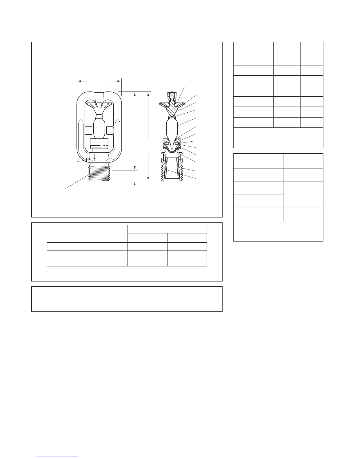
Components:
NOMINAL MAKE-IN
(1/4" & 3/8"
NPT
Page 2 of 6
-
Frame1
-
2 Deector
-
Upper Bulb Seat
3
-
4
Lower Bulb Seat
SIZE
STAMPED ON
WRENCHING
AREA FOR
1/4" & 3/8"
ORIFICE
1/2"
-
5
Pin
-
6 Button
-
7 Spacer
-
8 Spring Plates
1-3/4"
(44,5 mm)
7/16" (11,1 mm)
FIGURE 1
TYPE EA-1 PROTECTOSPRAY NOZZLE
NOMINAL DIMENSIONS
ORIFICE
SIZE
Inches
1/4 0.220 (5,59) 1.4 20,2
3/8 0.312 (7,92) 2.8 40,3
1/2 0.435 (11,05) 5.6 80,6
MINIMUM
DIAMETER
Inches (mm)
TABL E A
SELECTION OF ORIFICE SIZES
65° 95° 80° 110 ° 125° 140 ° 160° 180°
TABL E B
SELECTION OF SPR AY ANGLES
Design
Criteria
Nozzle Placement
Where direct impingement of water
spray onto all of the protected surface
is required by the authority having jurisdiction, the nozzles are to be spaced
and directed so that their spray patterns will completely cover the planeof-protection with the minimum
required average density. However, it
is recommended that indoor nozzle
spacing be 12 ft (3,7 m) or less and that
outdoor nozzle spacing be 10 ft (3,0 m)
or less. Where rundown or slippage is
planned, for example, exposure protec-
-
9
Lower Bulb
Gasket
-
Gasket10
-
11 Bulb
3"
(76,2 mm)
3-7/16"
(87,3 mm)
K-FACTO R
GPM/psi
tion of vessels per NFPA 15, the above
½
-
12 Bushing
orice only)
SPRAY ANGLE
MARKING
11
10
12
LPM/bar
½
2
5
3
9
4
7
8
6
1
recommended indoor and outdoor
spacings also apply.
When used for protecting the surfaces
of a vessel, for example, the nozzles
are positioned normal to and approximately 2 ft (0,6 m) from the surface.
This approach, in conjunction with
a properly selected spray angle, will
tend to make more effective use of the
spray as well as help minimize the disturbance effects of wind/draft conditions on the water spray patterns.
Spray Patterns
The Design Spray Profiles for the nozzle
spray angles of 65 to 180 degrees are
shown in Figure 2 and apply to discharge pressures of 20 to 60 psi (1,4
TEMPERATURE
RATI NG
135° F (57 °C) Unpainted Orange
175°F ( 7 9 °C) White Yell o w
250°F (121°C) Blue Blue
325°F (163°C ) Red Mauve
400°F (204°C) Green Black
500°F (260°C) Orange Black
FRAME
COLOR
CODE
BULB
CODE
COLOR
LIQUID
TABL E C
SELECTION OF
TE M P E R AT U R E RATING S
FINISH &
MAT E RIAL
Natural Finish
Bronze
Chrome Plated
Bronze
Lead Coated
Bronze
Corrosion-Resistant
Wax-Coated Bronze
TEMPERATURE
RATI NGS
All Ratings
135° F (57 °C)
175°F ( 7 9 °C)
250°F (121°C)
325°F (163°C )
135° F (57 °C)
175°F ( 7 9 °C)
TABL E D
SELECTION OF
FINISH AND MATERIALS
to 4,1 bar). Discharge pressures in
excess of 60 psi (4,1 bar) will result in a
decrease in coverage area because the
spray patterns tend to draw inwards
at higher pressures. Refer inquiries
on higher discharge pressures to the
Technical Services Department.
The maximum axial distances between
the nozzle tip and plane-of-protection,
for exposure protection, are given in
Table E and F. When the axial distance
from the nozzle tip to the plane-ofprotection is 2 ft (0,6 m) or less, the
Design Spray Profile is the same as
the nominal spray angles of 65 to 140
degrees.
Heat Sensitivity
Because the Type EA-1 PROTECTOSPRAY Directional Spray Nozzles
are automatic nozzles, they must be
located with consideration of their
ability to detect abnormal temperature increases due to fire. Therefore,
it is recommended that NFPA 13 be
reviewed with respect to the rules
that define the permitted distance
below ceilings and the spacing limitations for standard coverage automatic
sprinklers as a function of occupancy
hazard.
Page 3

TFP800
65°
110°
125°
140°
160°
180°
16
RADIAL DISTANCE FROM
AXIAL DISTANCE FROM NOZZLE, FEET
125°
140°
160°
110°
65°
180°
AXIAL DISTANCE FROM NOZZLE, METRES
RADIAL DISTANCE FROM
GRAVITY
(ORIENTATION)
PROTECTION
Page 3 of 6
NOZZLE CENTERLINE, FEET
0
2 4 6 8
0
2
4
6
8
10
12
14
NOZZLE
SPRAY
PROFILE
FIXED ANGLE
NOTES:
1. Desig n data obtaine d from tes ts in still air.
2. Design dat a applies to a resi dual (owing) pr essur e range a t the noz zle inle t of 20 to 60 ps i (1,4 to 4,1 bar). For
press ures up to 175 psi (12,1 bar) con sult Johnson C ontrol s Technica l Ser vices .
Refer to th e autho rity having jurisdic tion fo r their minimum required resi dual pr essur es.
3. T he shapes of the D esign Spray Pr oles remain e ssent ially unchanged over the maximum A xial Di stanc es show n
in Tables E and F.
4. F or axi al dist ances o f 2 feet (0,6 meters) and les s and for n ozzle s pray angles of 65° to 140°, the D esign Spray
Prole is t he same a s the nom inal sp ray angle.
5. T he maximum A xial D istan ces sh own in Tables E a nd F are ba sed on ex posur e protec tion.
WATER DISTRIBUTION DESIGN DATA
Main Pipeline Strainers
Main pipeline strainers per NFPA 15 are
required for systems utilizing nozzles
with a flow path less than 3/8 in. (9,5
mm) diameter, that is, K=1.4 (Table A),
and for any system where the water is
likely to contain obstructive material.
Installation
The TYCO Type EA-1 PROTECTOSPRAY Directional Spray Nozzles
must be installed in accordance with
this section.
95°
80°
FIGURE 2
NOZZLE CENTERLINE, METERS
2,52,01,51,00,50
0
0,5
1,0
1,5
2,0
2,5
3,0
3,5
4,0
4,5
AXIAL DISTANCE
PLANE OF
RADIAL
DISTANCE
95°
80°
NOTICE
Do not install an Type EA-1 Nozzle if
the bulb is cracked or there is a loss
of liquid from the bulb. With the sprinkler held horizontally, a small air bubble
should be present. The diameter of the
air bubble is approximately 3/32 in.
(2,4 mm) for the 135°F (57°C) to 1/4 in.
(6,4 mm) for the 500°F (260°C) temperature ratings.
Obtain a leak-tight 1/2 in. NPT nozzle
joint by applying a minimum-to-maximum torque of 7 to 14 ft-lb (9,5 to 19,0
N∙m). Higher levels of torque can distort
the nozzle inlet and cause leakage or
impairment of the nozzle.
FIGURE 3
W-T YPE 11
SPRINKLER WRENCH
Step 1. With pipe-thread sealant
applied to the pipe threads, handtighten the nozzle into the nozzle fitting.
Step 2. Tighten the nozzle into the
nozzle fitting using only the W-Type 11
Sprinkler Wrench (Figure 3), except that
an 8 in. or 10 in. adjustable crescent
wrench is to be used for wax-coated
nozzles. With reference to Figure 1,
the W-Type 11 Sprinkler Wrench or the
adjustable crescent wrench, as applicable, is to be applied to the wrenching area.
When installing wax-coated nozzles
with the adjustable crescent wrench,
exercise additional care to prevent
damage to the wax coating on the
nozzle wrenching area or frame
arms and, consequently, exposure of
bare metal to the corrosive environment. Sufficiently widen the jaws of
the wrench enough to pass over the
wrenching area without damaging the
wax coating. Before wrench-tightening the nozzle, adjust the jaws of the
wrench to contact the nozzle wrenching area. After wrench-tightening the
nozzle, loosen the wrench jaws before
removing the wrench.
After installation, inspect the nozzle
wrenching area and frame arms and
retouch (repair) the wax coating wherever the coating has been damaged
and bare metal is exposed. Retouch
the wax coating on the wrenching area
by gently applying a heated 1/8 in.
diameter steel rod to the areas of wax
that have been damaged, smoothing it
back over areas where bare metal is
exposed.
NOTICE
Only retouching of the wax coating
applied to the wrenching area and
frame arms is permitted, and the
retouching is to be performed only at
the time of the initial nozzle installation.
The steel rod should be heated only
to the point at which it can begin to
melt the wax, and appropriate precautions need to be taken when handling
the heated rod in order to prevent the
installer from being burned.
Page 4

TFP800
Page 4 of 6
Maximum Axial Distance
For 65° Spray Angle
In Feet and inches
Fixed
Angle
0°
30°
45°
60°
90°
120°
135°
150°
180°
Maximum Axial Distance
For 125° Spray Angle
In Feet and inches
Fixed
Angle
0°
30°
45°
60°
90°
120°
135°
150°
180°
Orifice Size
1/4
3/8
in.
in.
11- 9 14- 0 15 - 0
10- 0 12- 3 13-0
9-0 11- 3 12-3
8-6 10- 6 11- 9
7-6 10- 0 10- 9
6-3 7- 6 8-9
5-9 6-3 7- 9
5-3 5-6 7- 0
4-9 5-0 6-3
Orifice Size
1/4
3/8
in.
in.
4-6 7- 3 10 -0
4-3 6-9 8-3
3-9 6-3 7- 3
3-3 5-6 6-6
2-6 5-0 5-9
2-3 3-3 4-0
2-0 2-6 3-6
1-9 2-0 3-0
1-9 1-9 2-6
NOZZLE TIP AND PLANE-OF-PROTECTION FOR EXPOSURE PROTECTION
1/2
in.
1/2
in.
Maximum Axial Distance
For 80° Spray Angle
In Feet and inches
Fixed
Angle
0°
30°
45°
60°
90°
120°
135°
150°
180°
Maximum Axial Distance
For 140° Spray Angle
In Feet and inches
Fixed
Angle
0°
30°
45°
60°
90°
120°
135°
150°
180°
Orifice Size
1/4
3/8
in.
in.
10- 0 13- 0 14-0
8-3 11-3 11- 6
7-3 10 - 6 10-9
6-9 9-9 10 -3
6-0 8-9 9-6
5-3 6-3 7- 6
4-9 5-3 6-6
4-3 4-6 5-6
3-9 4-3 5-0
Orifice Size
1/4
3/8
in.
in.
4-0 6-0 9-3
3-6 5-9 7- 0
3-3 5-3 6-3
2-9 4-9 5-6
2-0 4-0 4-9
1-9 2-3 3-3
1-6 1-6 2-6
1-6 1-3 2-3
1-3 1-3 1-9
1/2
in.
1/2
in.
Maximum Axial Distance
For 95° Spray Angle
In Feet and inches
Fixed
Angle
0°
30°
45°
60°
90°
120°
135°
150°
180°
Maximum Axial Distance
For 160° Spray Angle
In Feet and inches
Fixed
Angle
0°
30°
45°
60°
90°
120°
135°
150°
180°
Orifice Size
1/4
3/8
in.
in.
7-0 10- 9 12-3
6-3 10-0 10 -6
6-0 9-6 9-6
5-9 9-0 9-0
5-0 7- 9 8-6
4-0 5-3 6-3
3-6 4-3 5-3
3-3 3-9 4-6
3-0 3-3 4-0
Orifice Size
1/4
3/8
in.
in.
3-6 5-0 7- 0
3-3 4-9 5-6
2-9 4-3 4-9
1-9 3-9 4-6
1-6 3-3 3-6
1-3 1-9 3-0
1-0 1-3 2-6
1-0 1-0 1-6
1-0 0-9 1-3
1/2
in.
1/2
in.
TABL E E
TYPE EA-1 PROTECTOSPRAY DIRECTIONAL SPRAY NOZZLES
MAXIMUM A XIAL DISTANCE IN FEET AND INCHES BETWEEN
Maximum Axial Distance
For 110° Spray Angle
In Feet and inches
Fixed
Angle
0°
30°
45°
60°
90°
120°
135°
150°
180°
Maximum Axial Distance
For 180° Spray Angle
In Feet and inches
Fixed
Angle
0°
30°
45°
60°
90°
120°
135°
150°
180°
Orifice Size
1/4
3/8
in.
in.
6-0 10- 0 11- 0
5-6 8-9 9-9
5-3 8-3 8-9
5-0 7- 6 8-3
4-6 6-6 7- 9
3-6 4-3 5-6
3-0 3-6 4-6
2-9 3-0 3-9
2-6 2-9 3-6
Orifice Size
1/4
3/8
in.
in.
3-0 3-9 6-0
2-9 3-6 5-0
2-6 3-0 4-3
2-3 2-9 3-9
1-3 1-9 3-0
0-9 1- 0 2-6
0-6 0-9 2-3
0-6 0-6 1-0
0-6 0-6 0-9
1/2
in.
1/2
in.
Care and
Maintenance
The TYCO Type EA-1 PROTECTOSPRAY Directional Spray Nozzles must
be maintained and serviced in accordance with this section.
Before closing a fire protection system
main control valve for maintenance
work on the fire protection system
that it controls, obtain permission to
shut down the affected fire protection
system from the proper authorities
and notify all personnel who may be
affected by this action.
Type EA-1 PROTECTOSPRAY Directional Spray Nozzles must never be
painted, plated, coated or altered in
any way after leaving the factory; otherwise, the spray performance and heat
sensitivity may be impaired.
Exercise care to avoid damage to the
nozzles before, during, and after installation. Replace nozzles damaged by
dropping, striking, wrench twist/slippage, or the like.
Frequent visual inspections are recommended to be initially performed
for nozzles installed in potentially corrosive atmospheres to verify the integrity of the materials of construction and
finish as they may be affected by the
corrosive conditions present for a given
installation. Thereafter, annual inspections per NFPA 25 are required.
The owner is responsible for the
inspection, testing, and maintenance of
their fire protection system and devices
in compliance with this document, as
well as with the applicable standards
of the National Fire Protection Association (e.g., NFPA 25), in addition to
the standards of any other authorities
having jurisdiction. Contact the installing contractor or product manufacturer
with any questions.
Water spray fixed systems are recommended to be inspected, tested,
and maintained by a qualified Inspection Service in accordance with local
requirements and/or national codes.
Page 5

TFP800
Page 5 of 6
Maximum Axial Distance
For 65° Spray Angle
In Meters
Fixed
Angle
0°
30°
45°
60°
90°
120°
135°
150°
180°
Maximum Axial Distance
For 125° Spray Angle
Fixed
Angle
0°
30°
45°
60°
90°
120°
135°
150°
180°
Orifice Size
1/4
3/8
in.
in.
3,6 4,3 4,6
3,0 3,7 4,0
2,7 3,4 3,7
2,6 3,2 3,6
2,3 3,0 3,3
1,9 2,3 2,7
1,8 1, 9 2,4
1,6 1,7 2 ,1
1,4 1, 5 1, 9
In Meters
Orifice Size
1/4
3/8
in.
in.
1,4 2,2 3,0
1,3 2,1 2,5
1,1 1,9 2,2
1,0 1,7 2,0
0,8 1,5 1,8
0,7 1,0 1,2
0,6 0,8 1,1
0,5 0,6 0,9
0,5 0,5 0,8
NOZZLE TIP AND PLANE-OF-PROTECTION FOR EXPOSURE PROTECTION
1/2
in.
1/2
in.
Maximum Axial Distance
For 80° Spray Angle
In Meters
Fixed
Angle
0°
30°
45°
60°
90°
120°
135°
150°
180°
Maximum Axial Distance
For 140° Spray Angle
Fixed
Angle
0°
30°
45°
60°
90°
120°
135°
150°
180°
Orifice Size
1/4
3/8
in.
in.
3,0 4,0 4,3
2,5 3,4 3,5
2,2 3,2 3,3
2,1 3,0 3,1
1,8 2,7 2,9
1,6 1, 9 2,3
1,4 1, 6 2,0
1,3 1, 4 1,7
1,1 1,3 1,5
In Meters
Orifice Size
1/4
3/8
in.
in.
1,2 1,8 2,8
1,1 1,8 2 ,1
1,0 1, 6 1, 9
0,8 1,4 1,7
0,6 1,2 1,4
0,5 0,7 1,0
0,5 0,5 0,8
0,5 0,4 0,7
0,4 0,4 0,5
1/2
in.
1/2
in.
Maximum Axial Distance
For 95° Spray Angle
In Meters
Fixed
Angle
0°
30°
45°
60°
90°
120°
135°
150°
180°
Maximum Axial Distance
For 160° Spray Angle
Fixed
Angle
0°
30°
45°
60°
90°
120°
135°
150°
180°
Orifice Size
1/4
3/8
in.
in.
2,7 3,3 3,7
1,9 3,0 3,2
1,8 2,9 2,9
1,8 2,7 2,7
1,5 2,4 2,6
1,2 1,6 1, 9
1,1 1,3 1,6
1,0 1,1 1,4
0,9 1,0 1,2
In Meters
Orifice Size
1/4
3/8
in.
in.
1,1 1,5 2 ,1
1,0 1, 4 1,7
0,8 1,3 1,4
0,5 1,1 1,4
0,5 1,0 1,1
0,4 0,5 0,9
0,3 0,4 0,8
0,3 0,3 0,5
0,2 0,3 0,4
1/2
in.
1/2
in.
TABL E F
TYPE EA-1 PROTECTOSPRAY DIRECTIONAL SPRAY NOZZLES
MAXIMUM AXIAL DISTANCE IN METERS BETWEEN
Maximum Axial Distance
For 110° Spray Angle
In Meters
Fixed
Angle
0°
30°
45°
60°
90°
120°
135°
150°
180°
Maximum Axial Distance
For 180° Spray Angle
Fixed
Angle
0°
30°
45°
60°
90°
120°
135°
150°
180°
Orifice Size
1/4
3/8
in.
in.
1,8 3,0 3,4
1,7 2,7 3,0
1,6 2,5 2,7
1,5 2,3 2,5
1,4 2,0 2,4
1,1 1,3 1,7
0,9 1,1 1,4
0,8 0,9 1,1
0,8 0,8 1,1
In Meters
Orifice Size
1/4
3/8
in.
in.
0,9 1,1 1,8
0,8 1,1 1,5
0,8 0,9 1,3
0,7 0,8 1,1
0,4 0,5 0,9
0,2 0,3 0,8
0,2 0,2 0,7
0,2 0,2 0,3
0,2 0,2 0,2
1/2
in.
1/2
in.
Page 6

TFP800
Page 6 of 6
P/N 49 – XX X – X – XX X
K-FACTO R
7 K = 1.4
8 K = 2.8
9 K = 5.6
65 65°
80 80°
95 95°
10 110 °
25 125°
40 140 °
60 160°
81 180°
TYPE EA-1 PROTECTOSPRAY DIRECTIONAL SPRAY NOZZLES
Limited
Warranty
For warranty terms and conditions, visit
www.tyco-fire.com.
SPRAY ANGLE
FINISH and MATERIAL
1 NATURAL FINISH BRONZE
WAX COATED BRONZE
6
7
9 CHROME PLATED BRONZE
135°F to 175°F ONLY
LEAD COATED BRONZE
135°F to 325°F ONLY
TABL E G
PART NUMBER SELECTION
Ordering
Procedure
When placing an order, indicate the
full product name and part number
(P/N). Contact your local distributor
for availability.
Type EA-1 PROTECTOSPRAY
Directional Spray Nozzle
Specify:
• (1.4, 2.8, or 5.6) K-factor orice
• temperature rating
• nish/coating and material
• (degree) spray angle
• P/N (from Table G)
Sprinkler Wrench
Specify: W-Type 11 Sprinkler Wrench,
P/ N 5 6 -452-1-0 01
TEMPERATURE
RATI NG
(ALL FINISHES)
135 135°F (57° C)
175 175°F ( 7 9 °C)
250 25 0°F (121° C)
325 325°F (163°C)
TEMPERATURE
RATI NG
(NATURAL
FINISH BRONZE
ONLY )
400 400°F (204°C)
500 500°F (260°C)
1400 Pennbr ook Parkwa y, Lans dale, PA 1944 6 | Teleph one +1-215-362- 070 0
© 2018 John son Control s. All right s reserved. A ll specifica tions and ot her informa tion shown wer e current as o f document rev ision date an d are subject t o change wit hout notice.
NATIONAL FIRE P ROTECTION ASSOCIATIO N and NFPA are register ed trademarks of N ational Fire Protec tion Associati on;
INCONEL is a re gistered trade mark of Special Me tals Corporat ion
 Loading...