

Page 1

DV-5 Deluge Valve, Diaphragm Style,
1-1/2 thru 8 Inch (DN40 thru DN200),
Deluge System — Electric Actuation
General
Description
The DV-5 Deluge Valve (described in
Technical Data Sheet TFP1305) is a
diaphragm style valve that depends
upon water pressure in the Diaphragm
Chamber to hold the Diaphragm closed
against the water supply pressure.
When the DV-5 Valve is set for service,
the Diaphragm Chamber is pressurized
through the trim connections from the
inlet side of the system’s main control valve, for example an O.S.&Y. gate
valve or buttery valve (Ref. Figures 1
and 4).
Operation of an electrical device such
as a heat sensitive thermostat, smoke
detector, or electrical manual control
station signals the Deluge Valve Releasing Panel to energize the Solenoid
Valve. In turn, the energized Solenoid
Valve opens to release water from the
Diaphragm Chamber faster than it can
be replenished through the 1/8 inch
(3,2 mm) restriction provided by the
Model ASV-1 Automatic Shut-Off Valve
in the diaphragm supply connections
(Item 5 - Fig. 3A and 5, also described
in Technical Data Sheet TFP1384). This
results in a rapid pressure drop in the
Diaphragm Chamber and the force
differential applied through the Diaphragm that holds it in the set position
is reduced below the valve trip point.
The water supply pressure then forces
the Diaphragm open permitting water
to ow into the system piping, as well
as through the Alarm Port to actuate
the system alarms.
As water ows into the system, the pilot chamber of the Model ASV-1 Automatic Shut-Off Valve (Item 5 - Fig. 3A
and 5) becomes pressurized and the
ASV-1 automatically shuts off the diaphragm chamber supply ow to the
DV-5 Diaphragm Chamber. Shutting
off the diaphragm chamber supply ow
prevents the DV-5 Diaphragm Chamber
from becoming re-pressurized, thereby preventing inadvertent closing of the
DV-5 during a re (as may be the case
should the Solenoid Valve become deenergized after its initial operation).
NOTICE
The DV-5 Deluge Valve with Electric
Actuation Trim described herein must
be installed and maintained in compliance with this document, as well as
with the applicable standards of the
National Fire Protection Association, in
addition to the standards of any other
authorities having jurisdiction. Failure
to do so may impair the performance
of these devices.
The owner is responsible for maintaining their fire protection system
and devices in proper operating condition. Contact the installing contractor or product manufacturer with any
questions.
Worldwide
Contacts
www.tyco-fire.com
Page 1 of 14 OCTOBER 2014 TFP1320
Page 2
TFP1320
etc. (Fire Detection)
Page 2 of 14
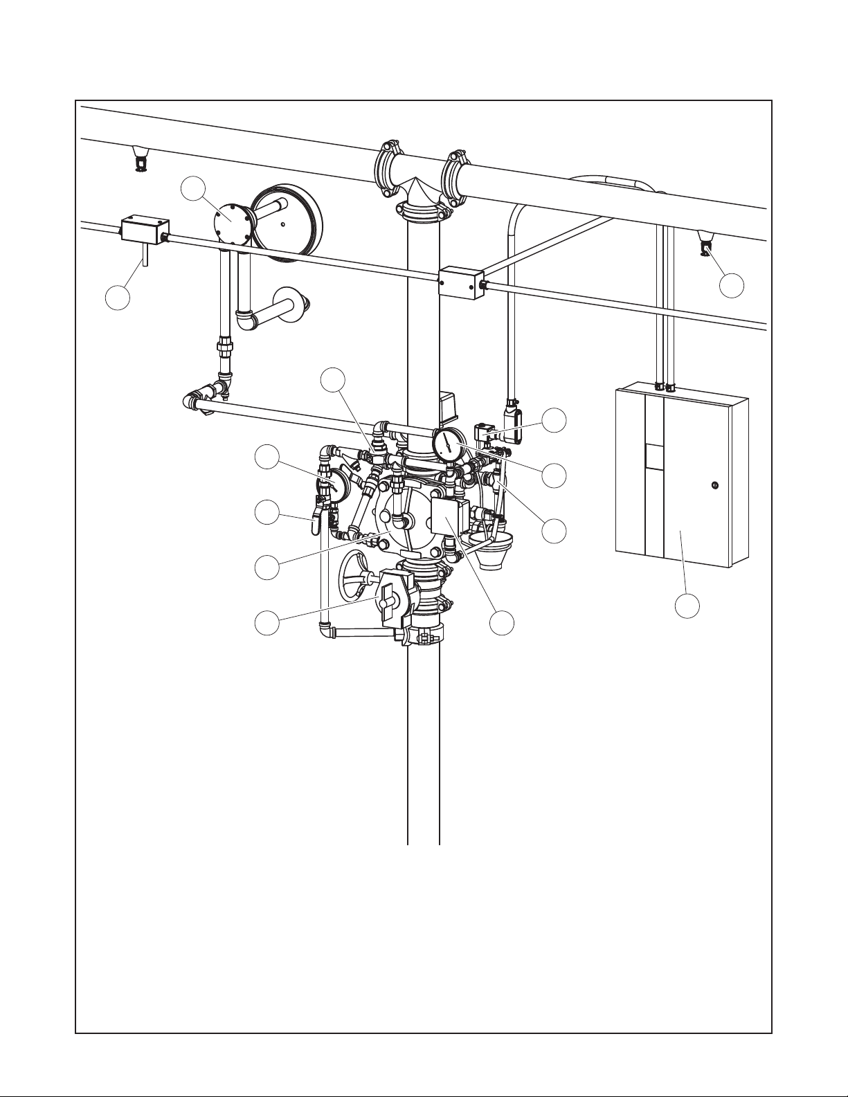
13
6
5
11
14
7
8
3
9
1
15
2
4
-
1
DV-5 Deluge Valve
-
2
Main Control Valve (N.O.)
-
3
Diaphragm Chamber Supply
Control Valve (N.O.)
-
4
Local Manual Control Station
-
5
Open Nozzles or Sprinklers
-
6
Heat Detectors, Smoke Detectors,
-
7
Water Supply Pressure Gauge
-
8
Diaphragm Chamber Pressure
Gauge
-
9
System Drain Valve (N.C.)
-
10
Main Drain Valve (N.C.)
(Shown at Rear of Valve)
-
11
Diaphragm Chamber Automatic
Shut-Off Valve
FIGURE 1 (1 OF 2)
SYSTEM SCHEMATIC (FRONT VIEW)
ELECTRIC ACTUATION
-
12
Waterow Pressure Alarm Switch
(Shown at Rear of Valve)
-
13
Water Motor Alarm (Optional)
-
14
Solenoid Valve
-
15
Deluge Valve Releasing Panel
Page 3

TFP1320
-
12
etc. (Fire Detection)
Waterow Pressure Alarm Switch
Page 3 of 14
6
5
15
14
12
13
11
9
3
10
1
2
-
1
DV-5 Deluge Valve
-
2
Main Control Valve (N.O.)
-
3
Diaphragm Chamber Supply
Control Valve (N.O.)
-
4
Local Manual Control Station
(Shown at Front of Valve)
-
5
Open Nozzles or Sprinklers
-
6
Heat Detectors, Smoke Detectors,
-
7
Water Supply Pressure Gauge
(Shown at Front of Valve)
-
8
Diaphragm Chamber Pressure
Gauge (Shown at Front of Valve)
-
9
System Drain Valve (N.C.)
-
10
Main Drain Valve (N.C.)
-
11
Diaphragm Chamber Automatic
Shut-Off Valve
SYSTEM SCHEMATIC (REAR VIEW)
ELECTRIC ACTUATION
FIGURE 1 (2 OF 2)
-
13
Water Motor Alarm (Optional)
-
14
Solenoid Valve
-
15
Deluge Valve Releasing Panel
Page 4
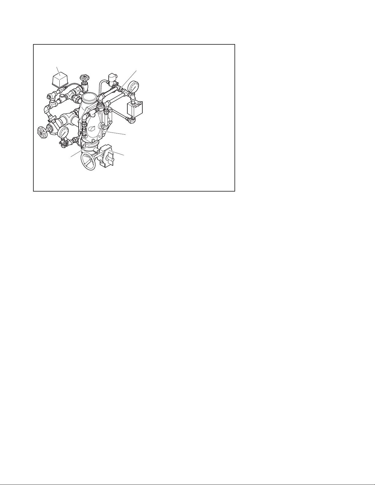
TRIM SHOWN FULLY ASSEMBLED;
COMPONENTS SUCH AS GAUGES
WATERFLOW
TFP1320
Page 4 of 14
PRESSURE
ALARM
SWITCH
DELUGE
SYSTEM
GROOVED
COUPLING
SHUT-OFF
FIGURE 2
DV-5 PRE-TRIMMED DELUGE VALVE
ELECTRIC ACTUATION
Technical
Data
Approvals
UL and C-UL Listed
FM Approved.
Valve Trim
The Vertical Electric Actuation Trim
(Fig. 3A/3B) and Horizontal Electric
Actuation Trim (Fig. 5) form a part of
the laboratory listings and approvals
for the DV-5 Valve and are necessary
for its proper operation.
Each package of trim includes the following items:
• Water Supply Pressure Gauge
• Diaphragm Chamber
Pressure Gauge
• Diaphragm Chamber Connections
• Manual Control Station
• Main Drain Valve
• System Drain Valve
• Alarm Test Valve
• Automatic Drain Valve
The following items are included in the
Pre-trimmed Valve Assembly and can
be ordered separately for the valve
trim:
• Model BFV-N Buttery Valve
• Waterow Pressure Alarm Switch
(PS10-2)
• Figure 577 Grooved Coupling
To ease eld assembly of the trim arrangement, the vertical trim components are provided partially assembled
as shown in Figure 3B.
DELUGE
ELECTRIC
ACTUATION
TRIM
NOTES:
1. SEE FIGURE 3, PER VALVE SIZE
AS APPLICABLE, FOR TRIM
ARRANGEMENT WITH BILL OF
MATERIALS AND COMPONENT
PART NUMBERS.
2.
DV-5
VALVE
VALVE
AND SWITCHES MAY REQUIRE
ASSEMBLY IN TRIM AT VALVE
INSTALLATION.
The trim arrangement is provided with
galvanized, black, or brass nipples and
ttings. The galvanized and brass trim
are intended for non-corrosive or corrosive conditions, whereas the black
trim is principally intended for use with
AFFF systems.
NOTE: When the system pressure is
greater than 175 psi (12,1 bar), provision
is to be made to replace the standard
order 300 psi (20,7 bar) Water Pressure
Gauges, shown in Figure 3A/3B and 5
with separately ordered 600 psi (41,4
bar) Water Pressure Gauges.
The Electric Actuation Trim is required
for electric operation of the DV-5 Valve
by a detection system consisting of
electrical devices such as heat sensitive thermostats, smoke detectors,
and/or electric manual pull stations.
Information on the various types of
separately ordered Solenoid Valves
that may be used with this trim package is given in Technical Data Sheet
TFP2180. Nominal installation dimensions for the Vertical Electric Actuation
Trim are shown in Figure 4.
NOTE: Approval by Factory Mutual is contingent on the use of an FM
Approved 24VDC Solenoid Valve. FM
only approves solenoid valves for use
in non-hazardous locations.
Consult with the authority having jurisdiction regarding installation criteria pertaining to electric actuation
circuitry.
The Electric Actuation Trim is provided
with a Model ASV-1 Automatic Shut-Off
Valve (Item 5 - Fig. 3A and 5); consequently, the release circuit of the Releasing Panel need only provide the
standard ten minutes of alarm condi-
tion intended to energize the Solenoid
Valve to open. After the ten minute duration, at which point should the Solenoid Valve become de-energized and
close (especially while operating under
battery back-up), the Automatic ShutOff Valve will have already automatically closed, thereby preventing the DV-5
Diaphragm Chamber from becoming
re-pressurized, and preventing an inadvertent closing of the DV-5 during a
re event.
Materials of
Construction
NOTES: The galvanized or brass nipples and fittings for the Valve Trim
provide corrosion resistance and are
intended to extend the life of the installation of the DV-5 Valve when exposed
to internal and external corrosive conditions. Although these selections are
intended to resist corrosion, it is recommended that the end user or other technical expert familiar with conditions at the proposed installation be
consulted with respect to these selections for a given corrosive condition.
Systems using a seawater or brackish
water supply require special considerations in order to extend the life of
the valve and trim. This type of system
ideally should be configured with a primary source of clean fresh water (e.g.,
a pressurized water tank) and that only
upon system operation is the secondary water supply (seawater or brackish water) allowed to enter the system.
After the system operation, the system should be thoroughly flushed with
clean fresh water. Following this recommendation will increase the service
life of the DV-5 Valve and Valve Trim.
Pressure Gauges. Bronze bourdon
tube with brass socket.
Gauge Test Valve. Bronze body per
ASTM B584.
Manual Control Station. Corrosion
resistant copper alloys and glass lled
PTFE seals. Thermoplastic enclosure.
Automatic Drain Valve. Brass body
per ASTM B584, Type 440 stainless
steel or brass per ASTM B134 Ball, and
galvanized steel inlet.
Automatic Shut-Off Valve. Brass
body, cover, and center seat per UNS
C36000, Type 316 stainless steel
spring, and Nylon fabric reinforced,
natural rubber diaphragm per ASTM
D2000.
Ball Valve. Corrosion resistant copper
alloys and glass lled PTFE seals.
Spring Loaded Check Valve. Brass
body and buna-n seal.
Page 5
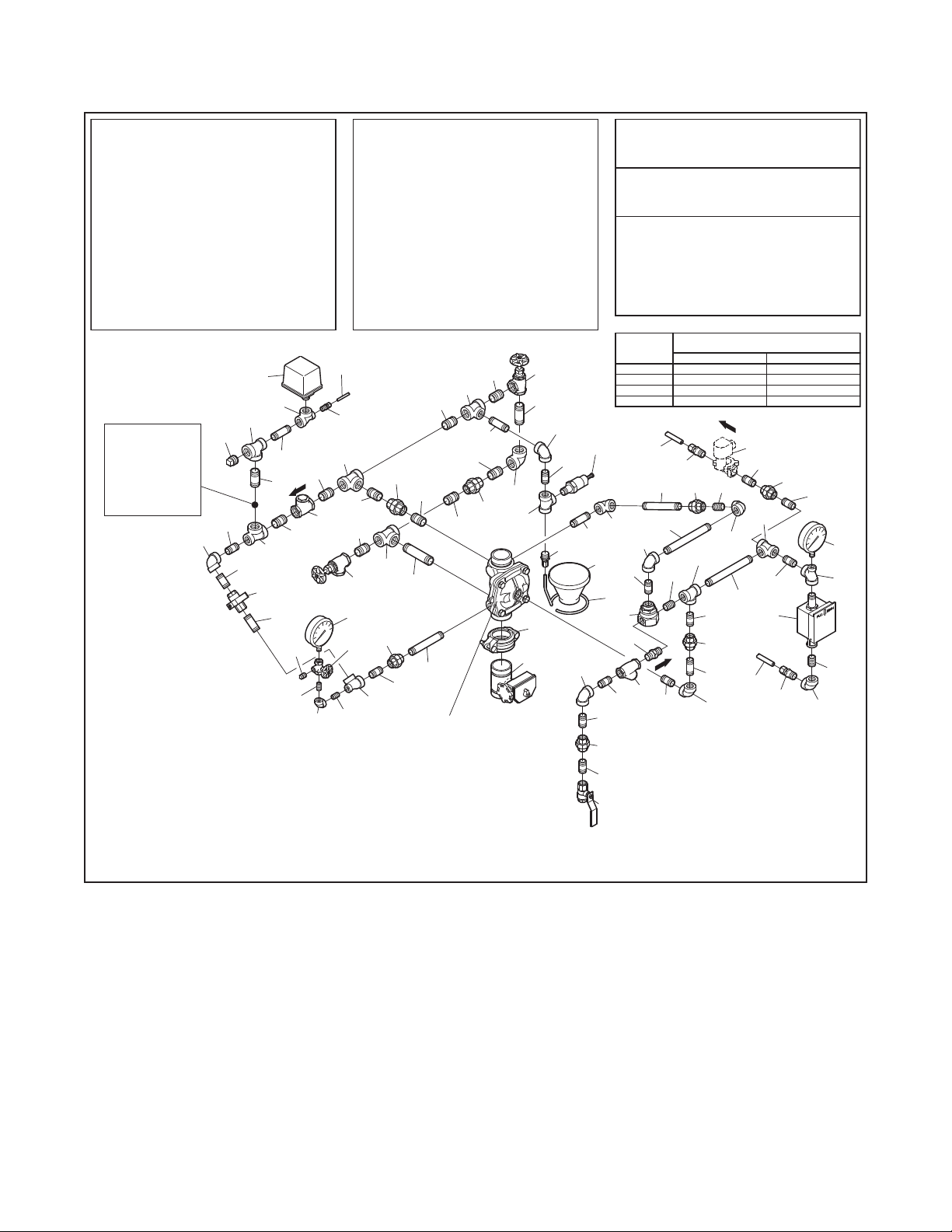
TFP1320
Item 14.
2.
3.
4.
5.
1.
NOTES:
Page 5 of 14
NO.
DESCRIPTION P/N
1
2
3
Model MC-1 Manual Control Station 52-289-2-001
4
Model AD-1 Automatic Drain Valve 52-793-2-004
5
6
Item No. Not Used
7
8
9
10 31
11
12
Drip Funnel Connector
Drip Funnel Bracket
13
Drip Funnel
14
15
16
1/4" x 18" Tubing CH
1/2" Tubing Connector CH
17
1/2" x 12" Tubing CH
18
. . . . . . . . . . . . . . . . . . . . . . . . . . . .
19
1/4" Plug CH
. . . . . . . . . . . . . . . . . . . . . . . . . . . .
20
3/4" Plug CH
21
1/2" Union CH
. . . . . . . . . . . . . . . . .
. . . . . . . . . . . . . . . . . . . . . . .
. . . . . . . . . . . . . . . . . . . . . . .
. . . . . . . . . . . . . . . . . . . . . . . . . . . . . . . . . . . .
. . . . . . . . . . . . . . . . . . . . . .
. . . . . . . . . . . . . . . . .
. . . . . . . . . . . . . . . . . . .
. . . . . . . . . . . . . . . . . . . . . . . . . .
. . . . . . . . . . . . . . . . . . . . .
. . . . . . . . . . . . . . . . . . . . .
. . . . . . . . . . . . . . . . .
. . . . . . . . . . . . . . . . . . . . .
. . . . . . . . . . . . . . . . . . . . . . . . . . .
QTY.
. .
2
92-343-1-005300 psi/ 2000 kPa Water Pressure Gauge
1
46-005-1-0021/4" Gauge Test Valve
1
. . . . . .
1
. . . . . . .
. . .
1
92-343-1-021Model ASV-1 Automatic Shut-Off Valve
2
. . . . . . . . .
46-050-1-0041/2" Ball Valve
1
92-322-1-0021/2" Spring Loaded Check Valve
1
52-353-1-0051/2" Y-Strainer
1 2
46-049-1-0053/4" Swing Check Valve 1/4" x Close Nipple CH
2
46-048-1-0053/4" Angle Valve
1
92-211-1-005
1
92-211-1-003
1
92-343-1-007
1
92-032-1-0023/32" Vent Fitting
1
1
1
1
1
5
A1
16
27
LOCATION
FOR OPTIONAL
ELECTRICALLY
SUPERVISED
N.O. ALARM
CONTROL
VALVE
29
20
35
43
33
24
29
(GREEN
TINT)
28
42
42
10
42
38
7
35
Electric Actuation Trim is
comprised of Items 1-45
19
plus Items E2-E4. Item E1
ordered separately. Items
A1-A3 included only in
pre-trimmed valve assemblies
as applicable; otherwise
ordered separately.
31
31
23
All Fittings and Nipples are
galvanized (Standard Order).
CH: Common Hardware.
See Figure 2 of TFP1305 for
Valve Port identication.
Route all Tubing to Drip Funnel,
NO. NO.
DESCRIPTION P/N DESCRIPTION P/N
22
23
24 45
25
26
27
28
29
30
32
33
34
35
36
37
38
39
40
41
42
. . . . . . . . . . . . . . . . . . . . . . . . . . .
3/4" Union CH
1/4" 90° Elbow CH
1/2" 90° Elbow CH
3/4" 90° Elbow CH
1/2" Tee CH
1/2" x 1/4" x 1/2" Tee CH
3/4" Tee CH
3/4" x 1/2" x 3/4" Tee
3/4" x 3/4" x 1/2" Tee CH
1/2" x Close Nipple CH
1/2" x 1-1/2" Nipple CH
1/2" x 2" Nipple CH
1/2" x 2-1/2" Nipple
1/2" x 5" Nipple CH
1/2" x 7" Nipple CH
Select Nipple per Table CH
Select Nipple per Table CH
Select Nipple per Table CH
3/4" x Close Nipple CH
3/4" x 1-1/2" Nipple
. . . . . . . . . . . . . . . . . . . . . . .
. . . . . . . . . . . . . . . . . . . . . . .
. . . . . . . . . . . . . . . . . . . . . . .
. . . . . . . . . . . . . . . . . . . . . . . . . . . .
. . . . . . . . . . . . . . . . . .
. . . . . . . . . . . . . . . . . . . . . . . . . . . .
. . . . . . . . . . . . . . . . . .
. . . . . . . . . . . . . . . . . .
. . . . . . . . . . . . . . . . . . . .
. . . . . . . . . . . . . . . . . . . .
. . . . . . . . . . . . . . . . . . . . . . .
. . . . . . . . . . . . . . . . . . . .
. . . . . . . . . . . . . . . . . . . . . . .
. . . . . . . . . . . . . . . . . . . . . . .
. . . . . . . . . . . . . . . .
. . . . . . . . . . . . . . . .
. . . . . . . . . . . . . . . .
. . . . . . . . . . . . . . . . . . . .
. . . . . . . . . . . . . . . . . . . .
30
15
42
42
22
42
42
42
28
11
44
1
21
2
36
39
27
2" (DN50)
GROOVE x GROOVE
DV-5 DELUGE VALVE
QTY. QTY.
2
1
8
1
3
3
2
2
CH
1
3
10
1
4
CH
2
1
1
1
1
1
8
CH
41
11
43
3/4" x 2" Nipple CH
44
3/4" x 4" Nipple CH
Select Nipple per Table CH
E1
Solenoid Valve Ordered Separately
Per Data Sheet TFP2180
E2
1/2" Tubing Connector CH
E3
1/2" x 24" Tubing CH
E4
1/2" x 1-1/2" Nipple CH
A1
Waterow Pressure Alarm Switch,
Model PS10-2 25710
A2
Buttery Valve, Power Ball 300:
A3
Figure 577 Coupling:
Nipple
Number
38
45
35
24
4
33
E3
25
22
26
12
24
35
24
14
33
. . . . . . . . . . . . . . . . . . . . . . .
. . . . . . . . . . . . . . . . . . . . . . .
COMPONENTS INCLUDED ONLY IN
PRE-TRIMMED VALVE ASSEMBLIES:
. . . . . . . . . . . . . . . . . . . . . . . .
. . . . . . . . . . . . . . . . . . . . . . . .
. . . . . . . . . . . . . . . . . . . . . . . . . . .
. . . . . . . . . . . . . . . . . . . . . . . .
. . . . . . . . . . . . . . . . . . . . . . . . . . .
1-1/2" (DN40)
1/2" x 1-1/2"
3/4" x 1-1/2"45
E2
36
21
40
26
32
13
A3
A2
5
8
24
9
33
33
33
21
. . . . . . . . . . . . . . . .
. . . . . . . . . . . . . . .
. . . . . . . . . . . . . . . . .
. . . . . . . . . . . . . . . . . . . . .
. . . . . . . . . . . . . . . . . . . .
Select Appropriate Nipple Sizes
per DV-5 Deluge Valve Size
1/2" x 2"39 1/2" x 1-1/2"
1/2" x 5"40
SEPARATELY)
32
24
37
33
21
34
18
24
SHOWN
33
7
1
1
1
1
1
1
1
1
1
1
1
1
2" (DN50)
1/2" x 5-1/2"
3/4" x 2-1/2"
E1
(ORDERED
E4
21
26
33
3
17
Refer to
Data Sheet
51024A1-1/2" (DN40)
51021A2" (DN50)
57715ACP1-1/2" (DN40)
57720ACP2" (DN50)
1/2" x 2"
33
1
27
32
24
1-1/2 AND 2 INCH (DN40 AND DN50) DV-5 DELUGE VALVES
EXPLODED VIEW OF VERTICAL ELECTRIC ACTUATION TRIM
Y-Strainer. Bronze body per ASTM
B584 and Type 304 stainless steel
screen.
Swing Check Valve. Bronze body per
ASTM B584 and buna-n seal.
Angle Valve. Bronze body per ASTM
B584 and nitrile disc (TEFLON disc for
2 inch size valve).
3/32” Vent Fitting. Brass per ASTM
B16.
Tubing Connector. Brass per ASTM
B16.
Tubing. Type L copper per ASTM B88.
FIGURE 3A (1 OF 3)
Pipe Fittings. Galvanized malleable iron per ANSI B16.3 or cast iron
per ANSI B16.4; black malleable iron
per ANSI B16.3 or cast iron per ANSI
B16.4; or, bronze per ANSI B16.15.
Pipe Nipples. Schedule 40 galvanized
steel per ASTM A53 or A135; Schedule 40 black steel per ASTM A53 or
A135; or, Schedule 40 red brass pipe
per ASTM B43.
Page 6

TFP1320
Item 15.
2.
3.
4.
5.
1.
NOTES:
Page 6 of 14
DESCRIPTION P/N
NO.
1 19
2
Model MC-1 Manual Control Station 52-289-2-001
3
Model AD-1 Automatic Drain Valve 52-793-2-004
4
5
Item No. Not Used
6
7
8
9
10
11
12
Drip Funnel Connector
13
Drip Funnel Bracket
14
Drip Funnel
15
16
1/4" x 18" Tubing CH
17
1/2" Tubing Connector CH
18
. . . . . . . . . . . . . . . . .
. . . . . . . . . . . . . . . . . . . . . . .
. . . . . . . . . . . . . . . . . . . . . . .
. . . . . . . . . . . . . . . .
. . . . . . . . . . . . . . . . . . . . . .
. . . . . . . . . . . . . . . . . . . .
. . . . . . . . . . . . . . . . .
. . . . . . . . . . . . . . . . . . .
. . . . . . . . . . . . . . . . . . . . . . . . . .
. . . . . . . . . . . . . . . . . . . . .
. . . . . . . . . . . . . . . . . . . . .
. . . . . . . . . . . . . . . . .
QTY.
2
. .
92-343-1-005300 psi/ 2000 kPa Water Pressure Gauge
1
46-005-1-0021/4" Gauge Test Valve
1
. . . . . .
1
. . . . . . .
1 1
92-343-1-021Model ASV-1 Automatic Shut-Off Valve
. . . . . . . . . . . . . . . . . . . . . . .
2
A1
46-050-1-0041/2" Ball Valve
1
92-322-1-0021/2" Spring Loaded Check Valve
1
52-353-1-0051/2" Y-Strainer
1
46-049-1-0053/4" Swing Check Valve
1
46-048-1-0053/4" Angle Valve
1
46-048-1-0071-1/4" Angle Valve
1
92-211-1-005
1
92-211-1-003
1
92-343-1-007
1
92-032-1-0023/32" Vent Fitting
1
1
17
. . . . . . . . .
28
LOCATION
FOR OPTIONAL
ELECTRICALLY
SUPERVISED
N.O. ALARM
CONTROL
VALVE
30
21
36
45
35
25
30
(GREEN
29
44
10
44
35
7
12
Electric Actuation Trim is
40
comprised of Items 1-48
plus Items E2-E4. Item E1
ordered separately. Items
20
A1-A3 included only in
pre-trimmed valve assemblies
as applicable; otherwise
ordered separately.
All Fittings and Nipples are
galvanized (Standard Order).
33
24
CH: Common Hardware.
See Figure 2 of TFP1305 for
Valve Port identication.
Route all Tubing to Drip Funnel,
DESCRIPTION P/N DESCRIPTION P/N
NO. NO.
1/2" x 12" Tubing CH
1/4" Plug CH
20
21
3/4" Plug CH
1/2" Union CH
22
3/4" Union CH
23
1/4" 90° Elbow CH
24
1/2" 90° Elbow CH
25
3/4" 90° Elbow CH
26
1/2" Tee CH
27
1/2" x 1/4" x 1/2" Tee
28
3/4" Tee CH
29
30
3/4" x 1/2" x 3/4" Tee
3/4" x 3/4" x 1/2" Tee CH
31
32
1-1/4" x 3/4" x 1-1/4" Tee CH
1/4" x Close Nipple CH
33
1/2" x Close Nipple CH
34
1/2" x 1-1/2" Nipple CH
35
1/2" x 2-1/2" Nipple
36
. . . . . . . . . . . . . . . . . . . . .
. . . . . . . . . . . . . . . . . . . . . . . . . . . .
. . . . . . . . . . . . . . . . . . . . . . . . . . . .
. . . . . . . . . . . . . . . . . . . . . . . . . . .
. . . . . . . . . . . . . . . . . . . . . . . . . . .
. . . . . . . . . . . . . . . . . . . . . . .
. . . . . . . . . . . . . . . . . . . . . . .
. . . . . . . . . . . . . . . . . . . . . . .
. . . . . . . . . . . . . . . . . . . . . . . . . . . .
. . . . . . . . . . . . . . . . . .
. . . . . . . . . . . . . . . . . . . . . . . . . . . .
. . . . . . . . . . . . . . . . . .
. . . . . . . . . . . . . . . . . .
. . . . . . . . . . . . . . .
. . . . . . . . . . . . . . . . . . . .
. . . . . . . . . . . . . . . . . . . .
. . . . . . . . . . . . . . . . . . . .
. . . . . . . . . . . . . . . . . . . .
31
16
TINT)
44
36
QTY. QTY.
1
1
1
5
2
1
8
1
3
3
CH
1
2
CH
1
1
2
2
13
2
CH
43
11
46
25
26
37
1/2" x 3-1/2" Nipple CH
1/2" x 4" Nipple CH
38
39
1/2" x 4-1/2" Nipple CH
1/2" x 5" Nipple CH
40
1/2" x 5-1/2" Nipple CH
41
1/2" x 7" Nipple CH
42
43
3/4" x Close Nipple CH
3/4" x 1-1/2" Nipple
44
3/4" x 2" Nipple CH
45
3/4" x 4-1/2" Nipple CH
46
1-1/4" x 2" Nipple CH
47
1-1/4" x 4" Nipple
48
E1
Solenoid Valve Ordered Separately
Per Data Sheet TFP2180
1/2" Tubing Connector CH
E2
1/2" x 24" Tubing CH
E3
1/2" x 1-1/2" Nipple CH
E4
A1
Waterow Pressure Alarm Switch,
Model PS10-2 25710
A2
Model BFV-N Buttery Valve, 3" (DN80) 59300F030N
A3
Figure 577 Coupling, 3" (DN80) 57730ACP
35
E3
. . . . . . . . . . . . . . . . . . . .
. . . . . . . . . . . . . . . . . . . . . . .
. . . . . . . . . . . . . . . . . . . .
. . . . . . . . . . . . . . . . . . . . . . .
. . . . . . . . . . . . . . . . . . . . . . .
. . . . . . . . . . . . . . . . . . . .
. . . . . . . . . . . . . . . . . . . .
. . . . . . . . . . . . . . . . . . . . . . .
. . . . . . . . . . . . . . . . . . . .
. . . . . . . . . . . . . . . . . . . . .
. . . . . . . . . . . . . . . . . . . . .
. . . . . . . . . . . . . . . . . . . . .
. . . . . . . . . . . . . . . . . . . .
COMPONENTS INCLUDED ONLY IN
PRE-TRIMMED VALVE ASSEMBLIES:
. . . . . . . . . . . . . . . . . . . . . . . .
. . . . . . . . . . . . . . .
. . . . . . . . . . . . . . . . .
E2
4
23
44
44
23
43
27
43
38
13
15
32
47
48
1
22
2
39
35
28
33
3" (DN80)
A2
A3
25
35
22
41
22
35
42
25
25
25
27
35
14
5
35
34
42
35
8
9
35
22
37
19
25
GROOVE x GROOVE
DV-5 DELUGE VALVE
SHOWN
35
7
1
1
1
1
2
3
5
1
1
1
1
1
1
1
1
1
1
. . .
1
. . . . . . . . . .
E1
(ORDERED
SEPARATELY)
E4
22
27
35
3
18
CH
CH
Refer to
Data Sheet
35
34
25
1
28
3 INCH (DN80) DV-5 DELUGE VALVE
FIGURE 3A (2 OF 3)
EXPLODED VIEW OF VERTICAL ELECTRIC ACTUATION TRIM
Page 7

TFP1320
Item 15.
2.
3.
4.
5.
1.
NOTES:
28
Page 7 of 14
. . . . . .
. . . . . . .
. . . . . . . . .
. . .
A1
QTY.
2
1
1
1
1
2
1
1
1
1
1
1
1
1
1
1
1
1
1
1
5
2
1
8
1
3
3
2
92-343-1-005300 psi/ 2000 kPa Water Pressure Gauge
46-005-1-0021/4" Gauge Test Valve
92-343-1-021Model ASV-1 Automatic Shut-Off Valve
46-050-1-0041/2" Ball Valve
92-322-1-0021/2" Spring Loaded Check Valve
52-353-1-0051/2" Y-Strainer
46-049-1-0053/4" Swing Check Valve
46-048-1-0061" Angle Valve
46-048-1-0092" Angle Valve
92-211-1-005
92-211-1-003
92-343-1-007
92-032-1-0023/32" Vent Fitting
CH
CH
17
DESCRIPTION P/N
NO.
1
2
3
Model MC-1 Manual Control Station 52-289-2-001
4
Model AD-1 Automatic Drain Valve 52-793-2-004
5
Item No. Not Used
6 35
7
8
9
10
11
12
13
Drip Funnel Connector
14
Drip Funnel Bracket
15
Drip Funnel
16
17
Select Tubing per Table CH
18
1/2" Tubing Connector CH
19
1/2" x 24" Tubing CH
. . . . . . . . . . . . . . . . . . . . . . . . . . . .
20
1/4" Plug CH
. . . . . . . . . . . . . . . . . . . . . . . . . . . .
21
3/4" Plug CH
22
1/2" Union CH
. . . . . . . . . . . . . . . . . . . . . . . . . . . .
23
1" Union CH
24
1/4" 90° Elbow CH
25
1/2" 90° Elbow CH
26
1" 90° Elbow CH
. . . . . . . . . . . . . . . . . . . . . . . . . . . .
27
1/2" Tee CH
28
1/2" x 1/4" x 1/2" Tee
3/4" x 1/2" x 3/4" Tee
29
. . . . . . . . . . . . . . . . .
. . . . . . . . . . . . . . . . . . . . . . .
. . . . . . . . . . . . . . . . . . . . . . .
. . . . . . . . . . . . . . . .
. . . . . . . . . . . . . . . . . . . . . . .
. . . . . . . . . . . . . . . . . . . . . . .
. . . . . . . . . . . . . . . . .
. . . . . . . . . . . . . . . . . . .
. . . . . . . . . . . . . . . . . . . . . . . . . .
. . . . . . . . . . . . . . . . . . . . .
. . . . . . . . . . . . . . . .
. . . . . . . . . . . . . . . . .
. . . . . . . . . . . . . . . . . . . . .
. . . . . . . . . . . . . . . . . . . . . . . . . . .
. . . . . . . . . . . . . . . . . . . . . . .
. . . . . . . . . . . . . . . . . . . . . . .
. . . . . . . . . . . . . . . . . . . . . . . . .
. . . . . . . . . . . . . . . . . .
. . . . . . . . . . . . . . . . . .
28
LOCATION
FOR OPTIONAL
ELECTRICALLY
SUPERVISED
N.O. ALARM
CONTROL
VALVE
29
21
36
45
35
25
29
16
(GREEN
TINT)
44
10
46
41
7
Electric Actuation Trim
is comprised of Items 1-52
plus Items E2-E4. Item E1
ordered separately. Items
A1-A3 included only in
40
20
pre-trimmed valve assemblies
as applicable; otherwise
ordered separately.
All Fittings and Nipples are
galvanized (Standard Order).
CH: Common Hardware.
33
24
See Figure 2 of TFP1305 for
Valve Port identication.
Route all Tubing to Drip Funnel,
NO.
DESCRIPTION P/N
1" x 1" x 1/2" Tee CH
30
1" x 3/4" x 1" Tee
31
2" x 1" x 2" Tee CH
32
33
1/4" x Close Nipple CH
1/2" x Close Nipple CH
34
1/2" x 1-1/2" Nipple CH
1/2" x 2-1/2" Nipple
36
37
Select Nipple per Table
1/2" x 5" Nipple CH
38
39
1/2" x 6" Nipple CH
40
1/2" x 7" Nipple CH
Select Nipple per Table CH
41
42
Select Nipple per Table CH
43
Select Nipple per Table CH
44
3/4" x 1-1/2" Nipple
45
3/4" x 2" Nipple CH
46
Select Nipple per Table CH
47
1" x Close Nipple CH
48
1" x 3" Nipple CH
49
Select Nipple per Table CH
50
2" x 3" Nipple CH
51
2" x 5" Nipple CH
52
Select Nipple per Table CH
E1
Solenoid Valve Ordered Separately
Per Data Sheet TFP2180
E2
1/2" Tubing Connector CH
E3
1/2" x 24" Tubing CH
E4
1/2" x 1-1/2" Nipple CH
. . . . . . . . . . . . . . . . . . . . .. .
. . . . . . . . . . . . . . . . . . . . .
. . . . . . . . . . . . . . . . . . . . . . .
. . . . . . . . . . . . . . . . . . . .
. . . . . . . . . . . . . . . . . . . .
. . . . . . . . . . . . . . . . . . . .
. . . . . . . . . . . . . . . . . . . .
. . . . . . . . . . . . . . . .
. . . . . . . . . . . . . . . . . . . . . . .
. . . . . . . . . . . . . . . . . . . . . . .
. . . . . . . . . . . . . . . . . . . . . . .
. . . . . . . . . . . . . . . .
. . . . . . . . . . . . . . . .
. . . . . . . . . . . . . . . .
. . . . . . . . . . . . . . . . . . . .
. . . . . . . . . . . . . . . . . . . . . . .
. . . . . . . . . . . . . . . .
. . . . . . . . . . . . . . . . . . . . .
. . . . . . . . . . . . . . . . . . . . . . . .
. . . . . . . . . . . . . . . .
. . . . . . . . . . . . . . . . . . . . . . . .
. . . . . . . . . . . . . . . . . . . . . . . .
. . . . . . . . . . . . . . . .
. . . . . . . . . . . . . . .
. . . . . . . . . . . . . . . . .
. . . . . . . . . . . . . . . . . . . . .
. . . . . . . . . . . . . . . . . . . .
30
47
23
31
23
47
47
48
32
50
51
12
1
22
2
38
35
28
33
4" (DN100)
GROOVE x GROOVE
DV-5 DELUGE VALVE
SHOWN
QTY.
1
1
CH
1
2
2
10
3
CH
1
CH
2
1
2
1
1
1
1
CH
1
1
5
1
1
1
1
1
Refer to
1
Data Sheet
1
1
1
47
11
NO.
A1
A2
A3
49
36
26
47
25
37
27
36
25
13
15
9
25
A3
A2
35
COMPONENTS INCLUDED ONLY IN
PRE-TRIMMED VALVE ASSEMBLIES:
DESCRIPTION P/N
Waterow Pressure Alarm Switch,
Model PS10-2 25710
Model BFV-N Buttery Valve:
Figure 577 Coupling:
Tube
No.
17
Nipple
No.
41
. . . . . . . . . . . . . . . . . . . . . . . .
. . . . . . . . . . . . . . . . . . . . . . . . . . .
. . . . . . . . . . . . . . . . . . . . . . . . . . .
. . . . . . . . . . . . . . . . . . . . . . . . . . .
. . . . . . . . . . . . . . . . . . . . . . . . . . .
. . . . . . . . . . . . . . . . . . . . . . . . . . .
. . . . . . . . . . . . . . . . . . . . . . . . . . .
Select Appropriate Tube Size
per DV-5 Deluge Valve Size
4" 6"
(DN100)
1/4" x 24"
Select Appropriate Nipple Sizes
per DV-5 Deluge Valve Size
4" 6"
(DN100)
1/2" x 3"37 1/2" x 3" 1/2" x 5"
1/2" x 2-1/2"
1/2" x 2"42
1/2" x 6-1/2"43
3/4" x 2-1/2"46
1" x 6"49 1" x 9"
1/2" x 7"52 1/2" x 7" 1/2" x 9"
E3
E2
4
39
22
42
43
25
25
(DN150)
1/4" x 24"
(DN150)
1/2" x 5-1/2"
1/2" x 3"
1/2" x 7-1/2"
3/4" x 3-1/2"
(ORDERED
SEPARATELY)
E4
27
QTY.
1
1
1
1
1
1
1
E1
22
27
35
14
5
35
34
35
52
35
8
22
38
25
3
19
18
35
59300F040N4" (DN100)
59300F060N6" (DN150)
59300F080N8" (DN200)
57740ACP4" (DN100)
57760ACP6" (DN150)
57780ACP8" (DN200)
8"
(DN200)
1/4" x 32"
8"
(DN200)
1/2" x 8-1/2"
1/2" x 3-1/2"
1/2" x 9"
3/4" x 4-1/2"
1" x 12"
35
25
1
34
22
35
7
4, 6, AND 8 INCH (DN100, DN150 AND DN200) DV-5 DELUGE VALVES
FIGURE 3A (3 OF 3)
EXPLODED VIEW OF VERTICAL ELECTRIC ACTUATION TRIM
Page 8

TFP1320
WATER SUPPLY
DIAPHRAGM
Page 8 of 14
WATERFLOW
PRESSURE ALARM
SWITCH, ORDERED
SEPARATELY
3/4 INCH NPT
CONNECTION FOR
WATER MOTOR
ALARM
LOCATION
FOR OPTIONAL
ELECTRICALLY
SUPERVISED
N.O. ALARM
CONTROL
VALVE
NIPPLE
Nipple
Number
Main Drain
1
DRAIN VALVE
(NORMALLY
CLOSED)
ALARM
TEST VALVE
(NORMALLY
CLOSED)
SYSTEM
WATER
SUPPLY
PRESSURE
GAUGE
1
Size
MAIN
1-1/2" (DN40)
1/2" x Close
1/2" x Close2
1/2" x 5"3
3/4" x 1-1/2"4
3/4" x 1-1/2"5 3/4" x 2-1/2"
1/2" x 1-1/2"6 1/2" x 1-1/2" 1/2" x 3" 1/2" x 3"1/2" x 1-1/2" 1/2" x 5"
1/2" x 7"7 1/2" x 7" 1/2" x 7" 1/2" x 7"1/2" x 7" 1/2" x 9"
3/4" NPT 3/4" NPT 2" NPT 2" NPT1-1/4" NPT
1/4" x 18"Tube 1 1/4" x 18" 1/4" x 24" 1/4" x 24"1/4" x 18" 1/4" x 32"
NIPPLE
1-1/4 INCH NPT
Select Appropriate Nipple and Tube Sizes per DV-5 Deluge Valve Size
VENT FITTING
(GREEN TINT)
B
4
NIPPLE
6
DRIP
FUNNEL
CONNECTION
TO DRAIN
A
C
2" (DN50)
1/2" x 2"
1/2" x Close
1/2" x 5-1/2"
3/4" x 1-1/2"
TUBE 1
DRAIN VALVE
(NORMALLY
AUTOMATIC
DRAIN VALVE
MAIN DRAIN
CONNECTION
(SIZED PER
TABLE)
3" (DN80)
1/2" x 1-1/2"
1/2" x 1-1/2"
1/2" x 7"
3/4" x 1-1/2"
3/4" x 4-1/2"
SYSTEM
CLOSED)
NIPPLE
DIAPHRAGM
CHAMBER SUPPLY
CONTROL VALVE
(NORMALLY
5
4" (DN100)
1/2" x 2-1/2"
1/2" x 2"
1/2" x 6-1/2"
3/4" x 2-1/2"
1" x 6" 1" x 9"
NOTES:
Install subassemblies in alphabetical order.1.
2.
See Figure 2 of TFP1305 for Valve Port
identication.
Route all Tubing to Drip Funnel.3.
When DV-5 trips, Automatic Shut-Off Valve
4.
shuts off diaphragm chamber supply.
5. Nipples 1-7 and Tube 1 vary in length relative
to DV-5 size. Select per table. All other nipples
and tubing packed unassembled shall be
installed per appropriate trim exploded view,
Figure 3A Part 1, 2, or 3.
4" (DN100)
FLANGE x FLANGE
DV-5 DELUGE
VALVE SHOWN
OPEN)
1/2 INCH NPT
CONNECTION FROM
6" (DN150)
1/2" x 5-1/2"
1/2" x 3"
1/2" x 7-1/2"
3/4" x 3-1/2"
D
SHUT-OFF VALVE
8" (DN200)
1/2" x 8-1/2"
1/2" x 3-1/2"
1/2" x 9"
3/4" x 4-1/2"
1" x 12"
2" NPT
1/2 INCH CONDUIT
CONNECTION FOR
"ELECTRIC DETECTION"
ORDERED SEPARATELY
NIPPLE
7
AUTOMATIC
(NORMALLY
OPEN)
SOLENOID VALVE,
(NORMALLY CLOSED)
NIPPLE
2
NIPPLE
3
CHAMBER
PRESSURE
GAUGE
MANUAL
CONTROL
STATION
1-1/2 THRU 8 INCH (DN40 THRU DN200) DV-5 DELUGE VALVES
FIGURE 3B
OPERATIONAL COMPONENTS OF VERTICAL ELECTRIC ACTUATION TRIM
EXPLODED ARRANGEMENT OF SEMI-PREASSEMBLED TRIM
Page 9

Nominal Installation Dimensions in Inches and (mm)
Valve
LEFT VIEW FRONT VIEW
Size
1-1/2"
DN40
2"
DN50
3"
DN80
4"
DN100
6"
DN150
8"
DN200
A
7.00
(177,8)
7.13
(181,0)
7.81
(198,4)
10.00
(254,0)
11.38
(289,0)
12.00
(304,8)
B
8.88
(225,4)
9.13
(231,8)
10.44
(265,1)
11.75
(298,5)
14.31
(363,5)
16.00
(406,4)
C
13.19
(335,0)
13.19
(335,0)
13.19
(335,0)
14.31
(363,5)
15.31
(388,9)
16.25
(412,8)
D
10.50
(266,7)
10.50
(266,7)
10.50
(266,7)
10.50
(266,7)
10.50
(266,7)
10.50
(266,7)
E
15.25
(387,4)
15.56
(395,3)
19.13
(485,8)
22.13
(562,0)
23.31
(592,1)
25.50
(647,7)
MINIMUM CLEARANCE
*
F
1.25
(31,8)
0.94
(23,8)
1.63
(41,3)
1.75
(44,5)
3.50
(88,9)
1.75
(44,5)
(147,6)
(152,4)
(170,0)
(217,5)
(252,4)
10.75
(273,1)
G
5.81
6.00
6.69
8.56
9.94
H
1.81
(46,0)
2.00
(50,8)
2.69
(68,3)
4.44
(112,7)
5.81
(147,6)
6.50
(165,1)
J
3.00
(76,2)
3.00
(76,2)
4.25
(108,0)
6.25
(158,8)
6.25
(158,8)
6.25
(158,8)
K
7.00
(177,8)
7.00
(177,8)
7.00
(177,8)
7.13
(181,0)
7.13
(181,0)
7.13
(181,0)
L
3.88
(98,4)
3.00
(76,2)
0.88
(22,2)
0.63
(15,9)
1.81
(46,0)
7.38
(187,3)
Page 9 of 14
M
8.00
(204,0)
8.63
(220,0)
12.75
(324,0)
15.75
(400,0)
18.13
(460,4)
22.50
(570,0)
TFP1320
N
4.02
(102,1)
4.09
(103,9)
3.85
(98,0)
4.56
(116,0)
5.86
(149,0)
5.26
(134,0)
* * *
F
H K
G
B
N
J
DCA
L
FIGURE 4
1-1/2 THRU 8 INCH (DN40 THRU DN200) DV-5 DELUGE VALVES
VERTICAL ELECTRIC ACTUATION / NOMINAL INSTALLATION DIMENSIONS
*
E
M
Page 10

TFP1320
SEPARATELY)
Page 10 of 14
NO. NO.
DESCRIPTION P/N DESCRIPTION P/N
10
11
12
Drip Funnel Connector
13
Drip Funnel Bracket
14
Drip Funnel
15 24
16
1/4" x 18" Tubing CH
17
1/2" Tubing Connector CH
18
1/2" x 12" Tubing CH
33
5
. . . . . . . . . . . . . . . .
. . . . . . . . . . . . . . . . . . . . . .
. . . . . . . . . . . . . . . . .
. . . . . . . . . . . . . . . . . . .
. . . . . . . . . . . . . . . . . . . . . . . . . .
. . . . . . . . . . . . . . . . . . . . .
. . . . . . . . . . . . . . . . . . . . .
. . . . . . . . . . . . . . . . .
. . . . . . . . . . . . . . . . . . . . .
24
E4
40
26
32
33
21
24
37
32
26
33
35
21
. . . . . .
. . . . . . .
. . . . . . . . .
33
QTY.
. .
2
92-343-1-005300 psi/ 2000 kPa Water Pressure Gauge
1
46-005-1-0021/4" Gauge Test Valve
1
1
. . .
1
92-343-1-021Model ASV-1 Automatic Shut-Off Valve
2
46-050-1-0041/2" Ball Valve
1
92-322-1-0021/2" Spring Loaded Check Valve
1
52-353-1-0051/2" Y-Strainer
33
NO.
DESCRIPTION P/N
1 19
2
3
Model MC-1 Manual Control Station 52-289-2-001
4
Model AD-1 Automatic Drain Valve 52-793-2-004
5
6
Item No. Not Used
7
8
9
. . . . . . . . . . . . . . . . .
. . . . . . . . . . . . . . . . . . . . . . .
. . . . . . . . . . . . . . . . . . . . . . .
33
1
19
7
2
GROOVE x GROOVE
DV-5 DELUGE VALVE
31
31
39
23
21
27
35
21
2" (DN50)
SHOWN
36
7
24
9
8
34
24
QTY. QTY.
1
46-049-1-0053/4" Swing Check Valve
2
46-048-1-0053/4" Angle Valve
1
92-211-1-005
1
92-211-1-003
1
92-343-1-007
1
92-032-1-0023/32" Vent Fitting
1
1
1
E2
E3
E1
(ORDERED
SEPARATELY)
33
1
21
33
27
3
36
LOCATION
FOR OPTIONAL
ELECTRICALLY
SUPERVISED
N.O. ALARM
CONTROL
VALVE
20
A1
(ORDERED
38
24
32
33
24
43
27
29
42
35
44
10
15
(GREEN
TINT)
22
42
42
18
42
26
28
35
30
16
29
24
17
4
14
12
42
11
42
22
42
28
41
45
25
11
13
42
. . . . . . . . . . . . . . . . . . . . . . . . . . . .
1/4" Plug CH
. . . . . . . . . . . . . . . . . . . . . . . . . . . .
20
3/4" Plug CH
21
22
23
25
26
27
28
29
30
31
32
33
34
35
36
37
38
39
40
41
42
43
44
45
E1
E2
E3
E4
A1
. . . . . . . . . . . . . . . . . . . . . . . . . . .
1/2" Union CH
. . . . . . . . . . . . . . . . . . . . . . . . . . .
3/4" Union CH
1/4" 90° Elbow CH
1/2" 90° Elbow CH
3/4" 90° Elbow CH
1/2" Tee CH
1/2" x 1/4" x 1/2" Tee CH
3/4" Tee CH
3/4" x 1/2" x 3/4" Tee
3/4" x 3/4" x 1/2" Tee CH
1/4" x Close Nipple CH
1/2" x Close Nipple CH
1/2" x 1-1/2" Nipple CH
1/2" x 2" Nipple CH
1/2" x 2-1/2" Nipple
1/2" x 5" Nipple CH
1/2" x 7" Nipple CH
Select Nipple per Table CH
Select Nipple per Table CH
Select Nipple per Table CH
3/4" x Close Nipple CH
3/4" x 1-1/2" Nipple
3/4" x 2" Nipple CH
3/4" x 4" Nipple CH
Select Nipple per Table CH
Solenoid Valve Ordered Separately
Per Data Sheet TFP2180
1/2" Tubing Connector CH
1/2" x 24" Tubing CH
1/2" x 1-1/2" Nipple CH
Waterow Pressure Alarm Switch,
Model PS10-2 25710
Nipple
Number
38
. . . . . . . . . . . . . . . . . . . . . . .
. . . . . . . . . . . . . . . . . . . . . . .
. . . . . . . . . . . . . . . . . . . . . . .
. . . . . . . . . . . . . . . . . . . . . . . . . . . .
. . . . . . . . . . . . . . . . . .
. . . . . . . . . . . . . . . . . . . . . . . . . . . .
. . . . . . . . . . . . . . . . . .
. . . . . . . . . . . . . . . . . .
. . . . . . . . . . . . . . . . . . . .
. . . . . . . . . . . . . . . . . . . .
. . . . . . . . . . . . . . . . . . . .
. . . . . . . . . . . . . . . . . . . . . . .
. . . . . . . . . . . . . . . . . . . .
. . . . . . . . . . . . . . . . . . . . . . .
. . . . . . . . . . . . . . . . . . . . . . .
. . . . . . . . . . . . . . . .
. . . . . . . . . . . . . . . .
. . . . . . . . . . . . . . . .
. . . . . . . . . . . . . . . . . . . .
. . . . . . . . . . . . . . . . . . . .
. . . . . . . . . . . . . . . . . . . . . . .
. . . . . . . . . . . . . . . . . . . . . . .
. . . . . . . . . . . . . . . .
. . . . . . . . . . . . . . .
. . . . . . . . . . . . . . . . .
. . . . . . . . . . . . . . . . . . . . .
. . . . . . . . . . . . . . . . . . . .
COMPONENTS ORDERED SEPARATELY:
. . . . . . . . . . . . . . . . . . . . . . . .
Select Appropriate Nipple Sizes
per DV-5 Deluge Valve Size
1-1/2" (DN40)
1/2" x 1-1/2"
1/2" x 2"39 1/2" x 1-1/2"
1/2" x 5"40
3/4" x 1-1/2"45
1
1
5
2
1
8
1
3
3
2
2
CH
1
2
3
10
1
4
CH
2
1
1
1
1
1
8
CH
1
1
1
Refer to
1
Data Sheet
1
1
1
1
2" (DN50)
1/2" x 2"
1/2" x 5-1/2"
3/4" x 2-1/2"
NOTES:
Electric Actuation Trim is comprised of
1.
Items 1-45 plus Items E2-E4. Items A1
and E1 ordered separately.
All Fittings and Nipples are galvanized
2.
(Standard Order).
CH: Common Hardware.
3.
See Figure 2 of TFP1305 for Valve Port
4.
identication.
Route all Tubing to Drip Funnel, Item 14.
5.
6. Horizontal Arrangement uses only 7 out of
8 of Item 24, and 9 out of 10 of Item 33.
Discard unused material.
1-1/2 AND 2 INCH (DN40 AND DN50) DV-5 DELUGE VALVES
EXPLODED VIEW OF HORIZONTAL ELECTRIC ACTUATION TRIM
Installation
General Instructions
Proper operation of the DV-5 Deluge
Valves depends upon their trim being
installed in accordance with the instructions given in this Technical Data
Sheet. Failure to follow the appropriate trim diagram may prevent the DV-5
Valve from functioning properly, as well
as void listings, approvals, and the
manufacturer’s warranties.
The DV-5 Valve must be installed in a
readily visible and accessible location.
The DV-5 Valve, associated trim, and
wet pilot lines must be maintained at
a minimum temperature of 40°F (4°C).
FIGURE 5 (1 OF 3)
Heat tracing of the DV-5 Valve or its
associated trim is not permitted. Heat
tracing can result in the formation of
hardened mineral deposits that are capable of preventing proper operation.
The DV-5 Deluge Valve is to be installed in accordance with the following criteria:
Step 1. All nipples, ttings, and devices must be clean and free of scale
and burrs before installation. Use pipe
thread sealant sparingly on male pipe
threads only.
Step 2. The DV-5 Valve must be
trimmed in accordance with Figure
3A/3B or 5.
Step 3. Care must be taken to ensure
that check valves, strainers, globe
valves, etc. are installed with the ow
arrows in the proper direction.
Step 4. Drain tubing to the Drip Funnel
must be installed with smooth bends
that will not restrict ow.
Step 5. The main drain and Drip Funnel
drain may be interconnected provided
a check valve is located at least 12
inches (300 mm) below the Drip Funnel.
Step 6. Suitable provision must be
made for disposal of drain water. Drainage water must be directed such that
it will not cause accidental damage to
property or danger to persons.
Step 7. Connect the Diaphragm Cham
ber Supply Control Valve to the inlet
side of the system’s Main Control Valve
in order to facilitate setting of the DV-5
Valve (Ref. Figure 4).
Step 8. Unused pressure alarm switch
connections must be plugged.
-
Page 11

. . . . . .
SEPARATELY)
Discard unused material.
. . . . . . .
QTY.
. .
2
1
1
1
. . .
1
NO.
DESCRIPTION P/N
1
2
3
Model MC-1 Manual Control Station 52-289-2-001
4
Model AD-1 Automatic Drain Valve 52-793-2-004
5
. . . . . . . . . . . . . . . . .
35
25
22
35
1
20
33
24
28
LOCATION
FOR OPTIONAL
ELECTRICALLY
SUPERVISED
N.O. ALARM
CONTROL
VALVE
7
2
33
3" (DN80)
GROOVE x GROOVE
DV-5 DELUGE VALVE
SHOWN
35
22
40
25
45
21
39
7
35
35
30
28
30
36
A1
(ORDERED
48
12
47
NO. NO.
DESCRIPTION P/N DESCRIPTION P/N
92-343-1-005300 psi/ 2000 kPa Water Pressure Gauge Item No. Not Used
46-005-1-0021/4" Gauge Test Valve
92-343-1-021Model ASV-1 Automatic Shut-Off Valve
35
6
7
8
9
10
25
35
9
8
34
5
37
25
22
35
27
35
38
23
44
10
44
44
16
(GREEN
TINT)
44
29
17
44
23
32
43
46
26
43
. . . . . . . . . . . . . . . . . . . . . . .
. . . . . . . . . . . . . . . . . . . . . . .
. . . . . . . . .
. . . . . . . . . . . . . . . .
E4
42
25
35
42
27
35
35
22
41
25
19
27
36
31
13
43
11
Page 11 of 14
QTY. QTY.
2
46-050-1-0041/2" Ball Valve
1
92-322-1-0021/2" Spring Loaded Check Valve
1
52-353-1-0051/2" Y-Strainer
1
46-049-1-0053/4" Swing Check Valve
E2
E1
(ORDERED
SEPARATELY)
1
22
28
34
25
18
4
15
11
12
13
Drip Funnel Connector
14
Drip Funnel Bracket
15
Drip Funnel
16
17
1/4" x 18" Tubing CH
18
1/2" Tubing Connector CH
19
1/2" x 12" Tubing CH
20
1/4" Plug CH
21
E3
3
3/4" Plug CH
1/2" Union CH
22
23
3/4" Union CH
1/4" 90° Elbow CH
24
25
1/2" 90° Elbow CH
3/4" 90° Elbow CH
26
1/2" Tee CH
27
28
1/2" x 1/4" x 1/2" Tee
3/4" Tee CH
29
30
3/4" x 1/2" x 3/4" Tee
31
3/4" x 3/4" x 1/2" Tee CH
32
1-1/4" x 3/4" x 1-1/4" Tee CH
33
1/4" x Close Nipple CH
34
1/2" x Close Nipple CH
35
1/2" x 1-1/2" Nipple CH
1/2" x 2-1/2" Nipple
36
1/2" x 3-1/2" Nipple CH
37
1/2" x 4" Nipple CH
38
1/2" x 4-1/2" Nipple CH
39
1/2" x 5" Nipple CH
40
1/2" x 5-1/2" Nipple CH
41
1/2" x 7" Nipple CH
42
3/4" x Close Nipple CH
43
3/4" x 1-1/2" Nipple
44
3/4" x 2" Nipple CH
45
3/4" x 4-1/2" Nipple CH
46
1-1/4" x 2" Nipple CH
47
1-1/4" x 4" Nipple
48
E1
Solenoid Valve Ordered Separately
Per Data Sheet TFP2180
E2
1/2" Tubing Connector CH
E3
1/2" x 24" Tubing CH
E4
1/2" x 1-1/2" Nipple CH
Waterow Pressure Alarm Switch,
A1
Model PS10-2 25710
NOTES:
Electric Actuation Trim is comprised of
1.
Items 1-48 plus Items E2-E4. Items A1
and E1 ordered separately.
All Fittings and Nipples are galvanized
2.
(Standard Order).
CH: Common Hardware.
3.
See Figure 2 of TFP1305 for Valve Port
4.
identication.
14
Route all Tubing to Drip Funnel, Item 15.
5.
6. Horizontal Arrangement uses only 7 out of
8 of Item 25, and 12 out of 13 of Item 35.
. . . . . . . . . . . . . . . . . . . . . .
. . . . . . . . . . . . . . . . . . . .
. . . . . . . . . . . . . . . . .
. . . . . . . . . . . . . . . . . . .
. . . . . . . . . . . . . . . . . . . . . . . . . .
. . . . . . . . . . . . . . . . . . . . .
. . . . . . . . . . . . . . . . . . . . .
. . . . . . . . . . . . . . . . .
. . . . . . . . . . . . . . . . . . . . .
. . . . . . . . . . . . . . . . . . . . . . . . . . . .
. . . . . . . . . . . . . . . . . . . . . . . . . . . .
. . . . . . . . . . . . . . . . . . . . . . . . . . .
. . . . . . . . . . . . . . . . . . . . . . . . . . .
. . . . . . . . . . . . . . . . . . . . . . .
. . . . . . . . . . . . . . . . . . . . . . .
. . . . . . . . . . . . . . . . . . . . . . .
. . . . . . . . . . . . . . . . . . . . . . . . . . . .
. . . . . . . . . . . . . . . . . .
. . . . . . . . . . . . . . . . . . . . . . . . . . . .
. . . . . . . . . . . . . . . . . .
. . . . . . . . . . . . . . . . . .
. . . . . . . . . . . . . . .
. . . . . . . . . . . . . . . . . . . .
. . . . . . . . . . . . . . . . . . . .
. . . . . . . . . . . . . . . . . . . .
. . . . . . . . . . . . . . . . . . . .
. . . . . . . . . . . . . . . . . . . .
. . . . . . . . . . . . . . . . . . . . . . .
. . . . . . . . . . . . . . . . . . . .
. . . . . . . . . . . . . . . . . . . . . . .
. . . . . . . . . . . . . . . . . . . .
. . . . . . . . . . . . . . . . . . . . . . .
. . . . . . . . . . . . . . . . . . . .
. . . . . . . . . . . . . . . . . . . .
. . . . . . . . . . . . . . . . . . . . . . .
. . . . . . . . . . . . . . . . . . . .
. . . . . . . . . . . . . . . . . . . . .
. . . . . . . . . . . . . . . . . . . . .
. . . . . . . . . . . . . . .
. . . . . . . . . . . . . . . . .
. . . . . . . . . . . . . . . . . . . . .
. . . . . . . . . . . . . . . . . . . .
COMPONENTS ORDERED SEPARATELY:
. . . . . . . . . . . . . . . . . . . . . . . .
13
TFP1320
1
46-048-1-0053/4" Angle Valve
1
46-048-1-0071-1/4" Angle Valve
92-211-1-005
1
1
92-211-1-003
1
92-343-1-007
1
92-032-1-0023/32" Vent Fitting
1
1
1
1
1
5
2
1
8
1
3
CH
3
1
CH
2
1
1
2
2
CH
2
1
1
1
1
1
2
3
CH
5
1
1
1
CH
1
Refer to
1
Data Sheet
1
1
1
1
3 INCH (DN80) DV-5 DELUGE VALVE
FIGURE 5 (2 OF 3)
EXPLODED VIEW OF HORIZONTAL ELECTRIC ACTUATION TRIM
Step 9. Conduit and electrical connections are to be made in accordance
with the requirements of the authority
having jurisdiction and/or the National
Electric Code.
Step 10. Before a system hydrostatic
test is performed in accordance with
NFPA 13 system acceptance test requirements, the DV-5 Diaphragm
Chamber is to be depressurized, the
Automatic Drain Valve (Item 4, Fig. 3A
and 5) is to be temporarily replaced
with a 1/2 inch NPT plug, the 3/32 inch
Vent Fitting (Item 16 - Fig. 3A and 5)
is to be temporarily replaced with a
1/4 inch NPT plug, and the Diaphragm
Cover Bolts must be uniformly and securely tightened using a cross-draw
sequence. After tightening, doublecheck to make certain that all of the
Diaphragm Cover Bolts are securely
tightened.
Page 12

TFP1320
SEPARATELY)
Page 12 of 14
DESCRIPTION P/N
NO.
1
2
3
Model MC-1 Manual Control Station 52-289-2-001
4 18
Model AD-1 Automatic Drain Valve 52-793-2-004 1/2" Tubing Connector CH
5
Item No. Not Used
6
7
8
9
10
11
12
Drip Funnel Connector
13
14
Drip Funnel Bracket
. . . . . . . . . . . . . . . . .
. . . . . . . . . . . . . . . . . . . . . . .
. . . . . . . . . . . . . . . . . . . . . . .
. . . . . . . . . . . . . . . .
. . . . . . . . . . . . . . . . . . . . . . .
. . . . . . . . . . . . . . . . . . . . . . .
. . . . . . . . . . . . . . . . .
. . . . . . . . . . . . . . . . . . .
QTY.
2
92-343-1-005300 psi/ 2000 kPa Water Pressure Gauge
. .
1
46-005-1-0021/4" Gauge Test Valve
1
. . . . . .
1 1
. . . . . . . . . . . . . . . . . . . . . . . .
1
92-343-1-021Model ASV-1 Automatic Shut-Off Valve
. . .
2
46-050-1-0041/2" Ball Valve
1
. . . . . . . . .
35
92-322-1-0021/2" Spring Loaded Check Valve
1
52-353-1-0051/2" Y-Strainer
1
46-049-1-0053/4" Swing Check Valve
1
46-048-1-0061" Angle Valve
1
46-048-1-0092" Angle Valve
1
92-211-1-005
1
92-211-1-003
35
25
22
9
35
1
20
33
2
33
24
28
40
LOCATION
FOR OPTIONAL
ELECTRICALLY
SUPERVISED
N.O. ALARM
CONTROL
VALVE
21
7
4" (DN100)
GROOVE x GROOVE
DV-5 DELUGE VALVE
SHOWN
35
22
38
7
41
35
25
45
25
29
46
28
29
51
A1
(ORDERED
36
50
12
32
DESCRIPTION P/N
NO.
15
16
17
19
20
21
22
23
24
25
26
27
28
. . . . . . . . . . . . . . . . . . . . . . . . . .
Drip Funnel
Select Tubing per Table CH
1/2" x 24" Tubing CH
1/4" Plug CH
3/4" Plug CH
1/2" Union CH
1" Union CH
1/4" 90° Elbow CH
1/2" 90° Elbow CH
1" 90° Elbow CH
1/2" Tee CH
1/2" x 1/4" x 1/2" Tee CH
. . . . . . . . . . . . . . . . . . . . .
. . . . . . . . . . . . . . . .
. . . . . . . . . . . . . . . . . . . . .
. . . . . . . . . . . . . . . . . . . . . . . . . . . .
. . . . . . . . . . . . . . . . . . . . . . . . . . . .
. . . . . . . . . . . . . . . . . . . . . . . . . . .
. . . . . . . . . . . . . . . . . . . . . . . . . . . .
. . . . . . . . . . . . . . . . . . . . . . .
. . . . . . . . . . . . . . . . . . . . . . .
. . . . . . . . . . . . . . . . . . . . . . . . .
. . . . . . . . . . . . . . . . . . . . . . . . . . . .
. . . . . . . . . . . . . . . . . .
25
35
8
5
34
43
38
27
35
22
52
35
39
36
25
23
48
10
44
47
31
16
(GREEN
TINT)
17
30
47
23
47
47
49
26
E4
25
27
42
22
27
37
47
QTY.
1
92-343-1-007
1
92-032-1-0023/32" Vent Fitting
1
1
1
1
5
2
1
8
1
3
3
(ORDERED
SEPARATELY)
35
22
35
18
19
4
13
11
E2
E1
14
(DN150)
1/4" x 24"
(DN150)
1/2" x 5-1/2"
1/2" x 3"
1/2" x 7-1/2"
3/4" x 3-1/2"
QTY.
10
2
1
1
1
2
2
3
1
2
1
2
1
1
1
1
1
1
5
1
1
1
1
1
1
1
1
1
1
CH
CH
CH
CH
CH
Refer to
Data Sheet
8"
(DN200)
1/4" x 32"
8"
(DN200)
1/2" x 8-1/2"
1/2" x 3-1/2"
1/2" x 9"
3/4" x 4-1/2"
1" x 12"
DESCRIPTION P/N
NO.
3/4" x 1/2" x 3/4" Tee
29
1" x 1" x 1/2" Tee CH
30
1" x 3/4" x 1" Tee
31
2" x 1" x 2" Tee CH
32
1/4" x Close Nipple CH
33
1/2" x Close Nipple CH
34
1/2" x 1-1/2" Nipple CH
35
1/2" x 2-1/2" Nipple
36
Select Nipple per Table
37
1/2" x 5" Nipple CH
38
1/2" x 6" Nipple CH
39
1/2" x 7" Nipple CH
40
Select Nipple per Table CH
41
Select Nipple per Table CH
42
Select Nipple per Table CH
43
3/4" x 1-1/2" Nipple
44
3/4" x 2" Nipple CH
45
Select Nipple per Table CH
46
1" x Close Nipple CH
47
E3
1
1" x 3" Nipple CH
48
Select Nipple per Table CH
49
2" x 3" Nipple CH
50
2" x 5" Nipple CH
51
Select Nipple per Table CH
52
Solenoid Valve Ordered Separately
E1
Per Data Sheet TFP2180
1/2" Tubing Connector CH
E2
1/2" x 24" Tubing CH
E3
1/2" x 1-1/2" Nipple CH
E4
COMPONENTS ORDERED SEPARATELY:
Waterow Pressure Alarm Switch,
A1
Model PS10-2 25710
28
Tube
No.
3
34
25
17
Nipple
No.
41
. . . . . . . . . . . . . . . . . .
. . . . . . . . . . . . . . . . . . . . .
. . . . . . . . . . . . . . . . . . . . .
. . . . . . . . . . . . . . . . . . . . . . .
. . . . . . . . . . . . . . . . . . . .
. . . . . . . . . . . . . . . . . . . .
. . . . . . . . . . . . . . . . . . . .
. . . . . . . . . . . . . . . . . . . .
. . . . . . . . . . . . . . . .
. . . . . . . . . . . . . . . . . . . . . . .
. . . . . . . . . . . . . . . . . . . . . . .
. . . . . . . . . . . . . . . . . . . . . . .
. . . . . . . . . . . . . . . .
. . . . . . . . . . . . . . . .
. . . . . . . . . . . . . . . .
. . . . . . . . . . . . . . . . . . . .
. . . . . . . . . . . . . . . . . . . . . . .
. . . . . . . . . . . . . . . .
. . . . . . . . . . . . . . . . . . . . .
. . . . . . . . . . . . . . . . . . . . . . . .
. . . . . . . . . . . . . . . .
. . . . . . . . . . . . . . . . . . . . . . . .
. . . . . . . . . . . . . . . . . . . . . . . .
. . . . . . . . . . . . . . . .
. . . . . . . . . . . . . . .
. . . . . . . . . . . . . . . . .
. . . . . . . . . . . . . . . . . . . . .
. . . . . . . . . . . . . . . . . . . .
. . . . . . . . . . . . . . . . . . . . . . . .
Select Appropriate Tube Size
per DV-5 Deluge Valve Size
4" 6"
(DN100)
1/4" x 24"
Select Appropriate Nipple Sizes
per DV-5 Deluge Valve Size
4" 6"
(DN100)
1/2" x 3"37 1/2" x 3" 1/2" x 5"
1/2" x 2-1/2"
1/2" x 2"42
1/2" x 6-1/2"43
3/4" x 2-1/2"46
1" x 6"49 1" x 9"
1/2" x 7"52 1/2" x 7" 1/2" x 9"
NOTES:
Electric Actuation Trim is comprised of
1.
15
Items 1-52 plus Items E2-E4. Items A1
and E1 ordered separately.
All Fittings and Nipples are galvanized
2.
(Standard Order).
CH: Common Hardware.
3.
See Figure 2 of TFP1305 for Valve Port
4.
identication.
Route all Tubing to Drip Funnel, Item 15.
5.
6. Horizontal Arrangement uses only 7 out of
8 of Item 25, and 2 out of 3 of Item 36.
Discard unused material.
4, 6, AND 8 INCH (DN100, DN150, AND DN200) DV-5 DELUGE VALVES
FIGURE 5 (3 OF 3)
EXPLODED VIEW OF HORIZONTAL ELECTRIC ACTUATION TRIM
Page 13

TFP1320
Page 13 of 14
Valve Setting
Procedure
Steps 1 through 11 are to be performed
when initially setting the DV-5 Deluge
Valve; after an operational test of the
re protection system; or, after system
operation due to a re.
NOTE: When the system is using either a seawater or brackish water supply, it is recommended that the system
be thoroughly flushed with clean fresh
water. Following this recommendation
will increase the service life of the DV-5
Valve and Trim.
Step 1. Close the Main Control Valve.
Step 2. Close the Diaphragm Chamber
Supply Control Valve.
Step 3. Open the Main Drain Valve,
System Drain Valve, and all auxiliary
drains in the system. Close the System
Drain Valve and auxiliary drain valves
after water ceases to discharge. Leave
the Main Drain Valve open.
Step 4. Depress the plunger of the Automatic Drain Valve to verify that it is
open and that the DV-5 Valve is completely drained.
Step 5. Clean the Strainer in the Diaphragm Chamber Supply connection
by removing the clean-out plug and
strainer basket. The Strainer may be
ushed out by momentarily opening
the Diaphragm Chamber Supply Control Valve.
Step 6. Reset the actuation system.
Manual Actuation — Push the operating lever up; however, do not close the
hinged cover at this time.
Electric Actuation — Reset the electric
detection system in accordance with
the manufacturer’s instructions to deenergize the solenoid valve.
Step 7. Open the Diaphragm Chamber
Supply Control Valve and allow time
for full pressure to build up in the Diaphragm Chamber.
Step 8. Operate (open) the Manual Control Station to vent trapped air
from the Diaphragm Chamber. If necessary, rst open the hinged cover, and
then fully pull down on the operating
lever. Slowly close the operating lever,
by pushing it up, after aerated water
ceases to discharge from the Manual
Control Station drain tubing. Close the
hinged cover and insert a new break
rod in the small hole through the top of
the enclosing box.
Step 9. Inspect the drain connections
from the Manual Control Station and
Solenoid Valve. Any leaks must be corrected before proceeding to the next
step.
Step 10. Verify the ability for the DV-5
Diaphragm to hold pressure as follows:
With the diaphragm chamber pressurized per Step 8, temporarily close the
Diaphragm Chamber Supply Control
Valve, and then monitor the Diaphragm
Chamber Pressure Gauge for a drop in
pressure.
If a drop in pressure is noted, the DV-5
Diaphragm is to be replaced and/or any
leaks must be corrected before proceeding to the next step.
If the Diaphragm Chamber Pressure
Gauge indicates no drop in pressure,
re-open the Diaphragm Chamber Supply Control Valve and proceed to the
next step.
Ste p 11. Slowly open the Main Control Valve. Close the Main Drain Valve
as soon as water discharges from the
drain connection. Observe the Automatic Drain Valve for leaks. If there are
leaks, determine/correct the cause of
the leakage problem. If there are no
leaks, the DV-5 Valve is ready to be
placed in service and the Main Control
Valve must then be fully opened.
NOTE: When the Main Control Valve
is opened, the pressure on the Diaphragm Chamber may increase. This
increase in pressure is normal, and if
the pressure is greater than 250 psi
(17,2 bar), the pressure is to be relieved
by partially and temporarily opening
the Manual Control Station; however,
do not allow the pressure as indicated
on the Diaphragm Chamber Pressure
Gauge to drop below the supply pressure shown on the Water Supply Pressure Gauge, since this action may result in tripping of the DV-5 Valve.
After setting a re protection system,
notify the proper authorities and advise
those responsible for monitoring proprietary and/or central station alarms.
Care and
Maintenance
The following procedures and inspections must be performed as indicated,
in addition to any specic requirements
of the NFPA, and any impairment must
be immediately corrected.
Before closing a re protection system
Main Control Valve for maintenance
work on the re protection system that
it controls, permission to shut down the
affected re protection systems must
rst be obtained from the proper authorities and all personnel who may be
affected by this action must be notied.
Reset the DV-5 Deluge Valve in accordance with the Valve Setting Procedure
section.
The owner is responsible for the inspection, testing, and maintenance of
their re protection system and devices
in compliance with this document, as
well as with the applicable standards
of the National Fire Protection Association (e.g., NFPA 25), in addition to the
standards of any authority having jurisdiction. Contact the installing contractor or product manufacturer with any
questions.
It is recommended that automatic
sprinkler systems be inspected, tested,
and maintained by a qualied Inspection Service in accordance with local
requirements and/or national codes.
NOTICE
Some of the procedures outlined in
this section will result in operation of
the associated alarms. Consequently,
notification must first be given to the
owner and the fire department, central
station, or other signal station to which
the alarms are connected.
When the system is using either a seawater or brackish water supply, internal and external inspection of the DV-5
Valve and Trim is essential. Parts showing any signs of corrosion must be replaced to ensure the integrity of the
system.
Annual Operation Test Procedure
Proper operation of the DV-5 Valve (i.e.,
opening of the DV-5 Valve as during a
re condition) must be veried at least
once a year as follows:
Step 1. If water must be prevented
from owing beyond the riser, perform
the following steps:
• Close the Main Control Valve.
• Open the Main Drain Valve.
•
Open the Main Control Valve one turn
beyond the position at which water
just begins to ow from the Main
Drain Valve.
• Close the Main Drain Valve.
Step 2. Test the Deluge Valve Releas-
ing Panel in accordance with the manufacturer’s instructions to energize the
solenoid valve.
NOTE: Be prepared to quickly perform
Steps 3, 4, and 5, if water must be prevented from flowing beyond the riser.
Step 3. Verify that the DV-5 Valve has
tripped, as indicated by the ow of water into the system.
Step 4. Close the system’s Main Control Valve.
Step 5. Close the Diaphragm Chamber
Supply Control Valve.
Step 6. Reset the DV-5 Deluge Valve
in accordance with the Valve Setting
Procedure.
Page 14

TFP1320
Page 14 of 14
Quarterly Waterflow Alarm Test
Procedure
Testing of the system waterow alarms
must be performed quarterly. To test
the waterow alarm, open the Alarm
Test Valve, which will allow a ow of
water to the Pressure Alarm Switch
and/or Water Motor Alarm. Upon satisfactory completion of the test, close
the Alarm Test Valve.
Limited
Warranty
For warranty terms and conditions, visit
www.tyco-re.com.
Ordering
Procedure
NOTE: Part Numbers for factory pretrimmed DV-5 Valves are provided in
the Price Book.
DV-5 Semi-Preassembled Vertical
Electric Actuation Trim
Specify: (specify size and nish — galvanized is standard) Semi-Preassembled Vertical Electric Actuation Trim for
DV-5 Deluge Valves, P/N (specify):
1-1/2 & 2 Inch Galvanized ... P/N 52-477-2-309
1-1/2 & 2 Inch Black........ P/N 52-47 7-1- 30 9
1-1/2 & 2 Inch Brass........ P/N 52-477-3-309
3 Inch Galvanized ..........P/N 52- 477-2-106
3 Inch Black ...............P/N 52-477-1-10 6
3 Inch Brass .............. P/N 52-47 7-3-106
4, 6 & 8 Inch Galvanized .... P/N 52-477-2-3 03
4, 6 & 8 Inch Black ......... P/N 52-477-1-303
4, 6 & 8 Inch Brass .........P/N 52-477-3-303
DV-5 Unassembled Electric
Actuation Trim for Vertical or
Horizontal Installation
Specify: (specify size and nish — galvanized is standard) Unassembled
Electric Actuation Trim for Vertical or
Horizontal Installation of DV-5 Deluge
Valves, P/N (specify):
1-1/2 & 2 Inch Galvanized ... P/N 52-477-2-209
1-1/2 & 2 Inch Black.........P/N 52-477-1-209
1-1/2 & 2 Inch Brass........ P/N 52-477-3-209
3 Inch Galvanized ......... P/N 52-477-2-206
3 Inch Black ...............P/N 52-477-1-206
3 Inch Brass .............. P/N 52-477-3-206
4, 6 & 8 Inch Galvanized .... P/N 52-477-2-203
4, 6 & 8 Inch Black ..........P/N 52-477-1-203
4, 6 & 8 Inch Brass ......... P/N 52-477-3-203
Pre-trimmed DV-5 Assembly
Electric Actuation Trim
with Butterfly Valve
Specify: (size), G x G End Connection,
Pre-trimmed DV-5 Assembly with Buttery Valve, P/N (specify):
1-1/2 Inch G x G ...........P/N 52- 913 - 0-1AP
2 Inch G x G ..............P/N 5 2- 92 3-0 -1A P
3 Inch G X G ..............P/N 52- 9 33 - 0-1AP
4 Inch G x G ..............P/N 52 -9 43- 0 -1AP
6 Inch G x G ..............P/N 52 -9 63- 0 -1AP
8 Inch G x G ..............P/N 52-983-0-1AP
Pre-trimmed DV-5 Assembly
Electric Actuation Trim
without Butterfly Valve
Specify: (specify size), (specify) End
Connection, Pre-trimmed DV-5 Assembly without Buttery Valve, P/N
(specify):
1-1/2 Inch T x T ...........P/N 52-913-3-1AP
2 Inch T x T...............P/N 52-923-3-1AP
3 Inch F x F............... P/ N 52-93 3-1 -1AP
3 Inch F x G ..............P/N 52-933 -2-1AP
4 Inch F x F............... P/ N 52-94 3-1 -1AP
4 Inch F x G ..............P/N 52-943 -2-1AP
6 Inch F x F............... P/ N 52-96 3-1 -1AP
6 Inch F x G ..............P/N 52- 963 -2-1AP
8 Inch F x F............... P/ N 52-98 3-1 -1AP
8 Inch F x G ..............P/N 52-983 -2-1AP
Accessories
Refer to the Technical Data Sheets for
the following, as applicable, for details
and additional accessories:
600 PSI Water
Pressure Gauge . . . . . . .....P/N 92-343-1-004
Solenoid Valve for
Electric Actuation..............See TFP2180
Model PS10-2
Potter Electric
Waterow
Pressure
Alarm Switch . . . . . . . . . ...........P/N 25710
Model WMA-1 Water
Motor Alarm . . . . . . . . . ....P/N 52-6 30-1-0 01
Replacement Trim Parts
Specify: (description) for use with DV-5
Deluge Valve, P/N (see Figure 3A or 5).
Accessories
Refer to the Technical Data Sheets for
the following, as applicable, for details
and additional accessories:
600 PSI Water
Pressure Gauge ...........P/N 92-343-1-004
Model PS10-2
Potter Electric
Waterow
Pressure
Alarm Switch ...................P/N 25710
Model WMA-1 Water
Motor Alarm .............P/N 52 -6 3 0-1-0 01P
Model MC-1
Manual Control
Stations with
Galvanized
Connections for
Remote Wet Pilot
Actuation ................P/N 52-289-2-001
Replacement Trim Parts
Specify: (description) for use with DV-5
Deluge Valve, P/N (see Figure 3A or 5)
GLOBAL HEADQUARTERS | 1400 Pennbrook Parkway, Lansdale, PA 19446 | Telephone +1-215-362-0700
Copyright © 2014 Tyco Fire Products, LP. All rights reserved.
TEFLON is trademark of The DuPont Corporation.
 Loading...