

Page 1

S2498
Tomcat K7M
///
Revision 1.01
Copyright © TYAN Computer Corporation, 2005-2006. All rights reserved. No part of this manual
may be reproduced or translated without prior written consent from TYAN Computer Corp.
All registered and unregistered trademarks and company names contained in this manual are the
properties of their respective owners, including, but not limited to the following.
TYAN, Tomcat K7M S2498 are trademarks of TYAN Computer Corporation.
AMD, Geode and the combinations thereof are trademarks of AMD Corporation.
Award BIOS is a trademark of Phoenix Technology.
Microsoft, Windows are trademarks of Microsoft Corporation.
IBM, PC, AT, PS/2 are trademarks of IBM Corporation.
Realtek is a trademark of Realtek Semiconductor Corporation.
Winbond is a trademark of Winbond Electronics Corporation.
Information contained in this document is provided by TYAN Computer Corporation and which has
been reviewed for accuracy and reliability before printing, however, TYAN assumes no liability and
disclaims any express or implied warranty relating to sale and/or use of TYAN products including
liability or warranties relating to fitness for a particular purpose or merchantability.
TYAN retains the right to make changes to product descriptions and/or specifications at any time,
without notice. In no event will TYAN be held liable for any direct or indirect, incidental or
consequential damage, loss of use, loss of data or other malady resulting from errors or
inaccuracies of information contained in this document.
1
http://www.TYAN.com
Page 2

Table of Contents
Before you begin…
Chapter 1: Introduction
1.1 Congratulations!
1.2 Hardware Specifications
Chapter 2: Board Installation
2.1 Board Image
2.2 Block Diagram
2.3 Board Parts, Jumpers and Connectors
2.4 Front Panel Connector (JP3)
2.5 CMOS Reset (JP13)
2.6 S/PDIF Header (J1)
2.7 USB Header (JP2)
2.8 Audio Header (J5)
2.9 LAN1 LED Header (JP8, JP14)
2.10 *LAN2 LED Header (*JP7,*JP15,*JP16)
2.11 VGA Header
2.12 Internal Audio Connector (CD_IN)
2.13 Mounting the Motherboard
2.14 Installing the Memory
2.15 Memory Installation Procedure
2.16 Installing the Processor and Heatsink
2.17 Attaching Drive Cables
2.18 Installing Add-In Cards
2.19 Connecting External Devices
2.20 Installing the Power Supply
2.21 Finishing Up
Chapter 3: BIOS Setup
3.1 Main BIOS Setup
3.2 Standard CMOS Features
3.3 Advanced BIOS Features
3.4 Advanced Chipset Features
3.5 Integrated Peripherals
3.6 Power Management Setup
3.7 PnP/PCI Configurations
3.8 PC Health Status
3.9 Frequency/Voltage Control
3.10 Load Fail-Safe Defaults
3.11 Load Optimized Defaults
3.12 Supervisor/User Password Setting
3.13 Exit Selecting
Chapter 4: Diagnostics
4.1 Beep Codes
4.2 Flash Utility
Appendix I: Glossary
Technical Support
……………………………………………..Page 3
……………………………………………..Page 4
……………………………………………..Page 4
……………………………………………..Page 4
……………………………………………..Page 6
……………………………………………..Page 7
……………………………………………..Page 8
……………………………………………..Page 9
…………………………………………….Page 11
……………………………………………..Page 12
……………………………………………Page 12
……………………………………………Page 13
……………………………………………Page 13
……………………………………………Page 14
……………………………………………Page 14
……………………………………………Page 15
……………………………………………Page 15
……………………………………………Page 16
……………………………………………Page 17
……………………………………………Page 17
……………………………………………Page 18
……………………………………………Page 19
……………………………………………Page 22
……………………………………………Page 23
……………………………………………Page 23
……………………………………………Page 24
……………………………………………Page 25
……………………………………………Page 27
……………………………………………Page 29
……………………………………………Page 31
……………………………………………Page 34
……………………………………………Page 39
……………………………………………Page 44
……………………………………………Page 48
……………………………………………Page 49
……………………………………………Page 50
……………………………………………Page 51
……………………………………………Page 51
……………………………………………Page 52
……………………………………………Page 53
……………………………………………Page 55
……………………………………………Page 55
……………………………………………Page 55
2
http://www.TYAN.com
Page 3
Before you begin…
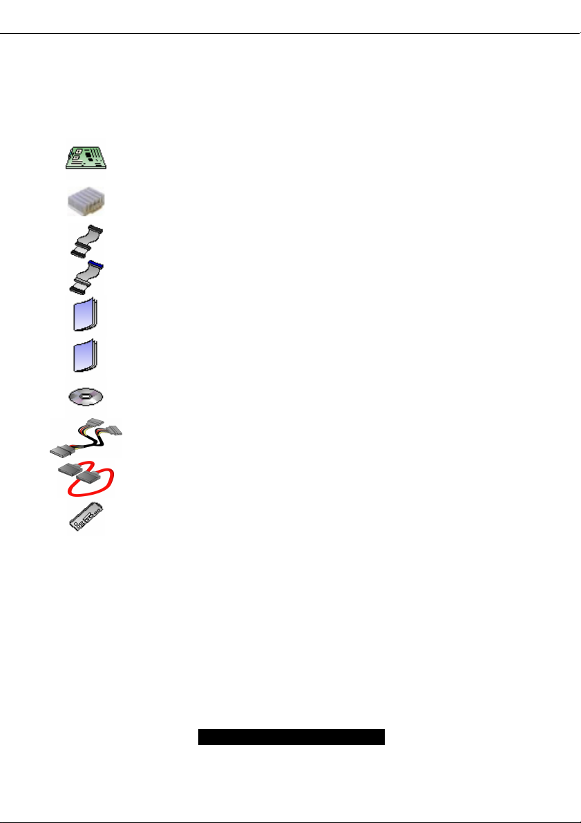
Check the box contents!
The retail motherboard package should contain the following:
1x Tomcat K7M motherboard
1x Ultra-DMA-133/100/66 IDE cable
If any of these items are missing, please contact your vendor/dealer for replacement before
continuing with the installation process.
1 x CPU heatsink
1x 34-Pin floppy drive cable
1x Tomcat K7M User’s Manual
1 x Tomcat K7M Quick Reference
1 x TYAN driver CD
1 x SATA Power Cable
1 x SATA DATA cable
1x I/O shield
3
http://www.TYAN.com
Page 4

Chapter 1: Introduction
1.1 – Congratulations!
You have just bought one of the most advanced platforms as a high Quality/reliable single board
computer. The Tomcat K7M is based on VIA KN400A chipset, supporting the AMD Geode NX
Processor with 133MHz FSB, DDR memory, VIA integrated Unichorme Graphics and more. These
features enable breakthrough performance for today’s rapidly developing multimedia applications.
Visit TYAN’s Website at http://www.TYAN.com
products with FAQ’s, distributor’s list and BIOS setting explanations.
1.2 – Hardware Specification
Processor
Single Socket A (Socket 462)
Support AMD Geode NX1250, NX1500 and
NX1750 CPU 453pin OPGA package.
Expansion Slots
Two 32Bit/33MHz PCI 2.3 Slots
Chipset
VIA KN400A chipset
VT8237
Winbond W83697HF LPC I/O chip
Realtek ALC655 AC’97 codec chip
Memory
Single memory channel
Supports up to two PC2100/2700 DIMMs
Up to 2GB of un-buffered Non-ECC memory
Integrated IDE
Dual channel master mode support up to four
IDE devices
Support for ATA-100/66/33 IDE drives and
ATAPI compliant devices
Integrated Serial ATA
Serial ATA Host controllers embedded
Two Serial ports running at 1.5Gb/s
Integrated LAN Controllers
One Integrated Realtek RTL8100C 10/100
Mbps Ethernet controller
Integrated Intel82541 Gigabit Ethernet
Controller. (AGNN version only)
. There you can find information on all of TYAN’s
Back Panel I/O Ports
Stacked PS/2 Mouse & Keyboard ports
Stacked USB 2.0 ports (4 ports total)
One 9-pin UART Serial port
One 15-pin VGA port
One 25-pin SPP/ECP/EPP parallel port
One RJ45 10/100 Base-T port
One RJ45 10/100/1000 Base-T port
(AGNN version only)
Vertical Mic-In/Line-In/Line-out audio jacks
(AGN version only)
Integrated I/O Interfaces
One Floppy connector for up to two drives
Two IDE connectors for up to four IDE
devices
Two SATA connectors for up to two devices
Two USB 2.0 Ports (via optional cable)
Pin headers for LAN LED/I
intrusion
Pin headers for 1*system Fans
Tyan 2 x 9 front panel connector
Com2 ports (pin header)
One integrated 11pin VGA pin header
CD Audio-input Connector
Mic, and Line-out pin header
S/PDIF out pin header
Integrated Graphics
Integrated S3 Graphics UniChorme
engine with MPEG-2 acceleration
Share memory: 16/32/64MB
2
C/Chassis
TM
2D/3D
4
http://www.TYAN.com
Page 5

BIOS
Award BIOS 4Mbit Flash
Supports APM 1.2 & ACPI 1.0
Auto detection of memory size
Auto configuration of IDE hard disk types
User settings of hardware monitoring
Multiple boot options
Power Management: S1, S3, S4
Support AMD PowerNow! ™ technology
OS (Operating System) Support
Microsoft Windows 2000
Microsoft Windows XP
Linux Redhat 8.0 and 9.0
Regulatory
FCC Class B (Declaration of Conformity)
European Community CE (Declaration of
Conformity)
Power
On board 2-phase VRM
ATX / ATX12V (20-pin) power connector
Form Factor
Flex ATX footprint
9” x 7.5” (228.6cm x 190.5mm)
5
http://www.TYAN.com
Page 6

Chapter 2: Board Installation
Installation
You are now ready to install your motherboard. The mounting hole pattern of the Tomcat K7M
matches the ATX system board specifications. Your chassis should support a standard ATX
motherboard form factor.
How to install our products right…. the first time!
The first thing you should do is read this user’s manual. It contains important information that will
make configuration and setup much easier. Here are some precautions you should take when
installing your motherboard:
(1) Ground yourself properly before removing your motherboard from the antistatic bag.
Unplug the power from your computer power supply and then touch a safely grounded
object to release static charge (i.e. power supply case). For the safest conditions, TYAN
recommends wearing a static safety wrist strap.
(2) Hold the motherboard by its edges and do not touch the bottom of the board, or flex the
board in any way.
(3) Avoid touching the motherboard components, IC chips, connectors, memory modules,
and leads.
(4) Place the motherboard on a grounded antistatic surface or on the antistatic bag that the
board was shipped in.
(5) Inspect the board for damage.
The following pages include details on how to install your motherboard into your chassis, as well
as installing the processor, memory, disk drives and cables.
NOTE DO NOT APPLY POWER TO THE BOARD IF IT HAS BEEN DAMAGED
6
http://www.TYAN.com
Page 7
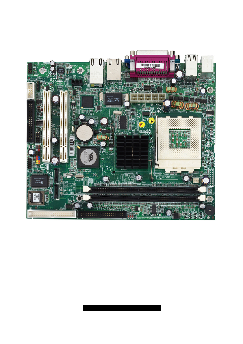
2.1 – Board Image
The following is an image of the Tomcat K7M 2498AGNN.
This picture is representative of the latest board revision available at the time of publishing.
The board you receive may or may not look exactly like the above picture.
The following page includes details on the vital components of this motherboard.
7
http://www.TYAN.com
Page 8
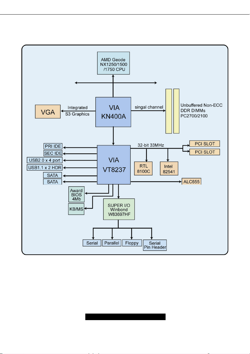
2.2 – Block Diagram
S2498 Tomcat K7M Block Diagram
8
http://www.TYAN.com
Page 9

2.3 – Board Parts, Jumpers and Connectors
* is only available on S2498AGNN version.
NOTE:
http://www.TYAN.com
9
Page 10
This jumper diagram is representative of the latest board revision available at the time of
publishing. The board you receive may or may not look exactly like the above diagram.
Function Settings
JP3
JP13
JP2
JP8, JP14
*JP7,*JP15
,*JP16
J37
CD_IN
J1
J5
Front Panel Connector
CMOS Reset
S/PDIF Header
USB Header
Audio Header
LAN1 LED Header
*LAN2 LED Header
VGA Header
Internal Audio Connector
http://www.TYAN.com
See Section 2.4 for pinout
configuration
Close Pin-1 and Pin-2 (Default)
Normal mode
Close Pin-2 and Pin-3
Clear CMOS mode
See Section 2.6 for pinout
configuration
See Section 2.7 for pinout
configuration
See Section 2.8 for pinout
configuration
See Section 2.9 for pinout
configuration
See Section 2.10 for pinout
configuration
See Section 2.11 for pinout
configuration
See Section 2.12 for pinout
configuration
10
Page 11
Jumper Legend
OPEN - Jumper OFF Without jumper cover
CLOSED - Jumper ON With jumper cover
To indicate the location of pin-1
To indicate the location of pin-1
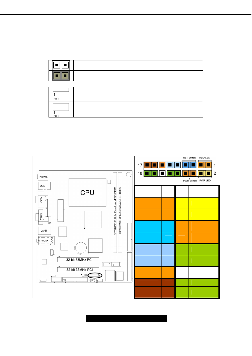
2.4 – Front Panel Connector (JP3)
Function
HDD
LED+
HDD
LED-
Reset
Button -
Reset
Button +
+5V 9 10 NC
NC 11 12 GND
+5VSUS 13 14 KEY
NC 15 16 GND
NC 17 18 INTRUDER
PIN # PIN
1 2 PWR LED+
3 4 PWR LED-
5 6
7 8
#
Function
PWR
Button+
PWR
Button-
11
http://www.TYAN.com
Page 12
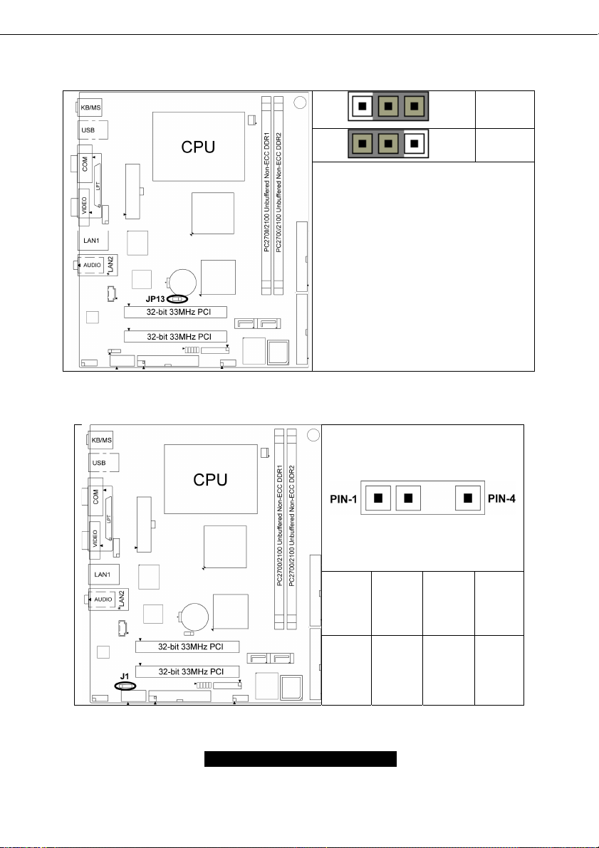
2.5– CMOS Reset (JP13)
2.6 – S/PDIF Header (J1)
Pin_3 Pin_1
Pin_3 Pin_1
You can reset the CMOS settings by
using this jumper if you have forgotten
your system/setup password or need to
clear system BIOS setting.
- Power off system and disconnect
both power connectors from the
motherboard
- Use jumper cap to close Pin_2 and
Pin_3 for several seconds to Clear
CMOS
- Put jumper cap back to Pin_1 and
Pin_2 (default setting)
Reconnect power & power on system
Default
Clear
Pin-1 Pin-2 Pin-3 Pin-4
SPDIF
_OUT
12
NC KEY GND
http://www.TYAN.com
Page 13
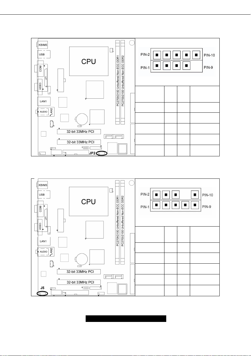
2.7– USB Header (JP2)
2.8– Audio Header (J5)
Signal
Description
USB VCC 1 2 USB VCC
USB DATA - 3 4 USB DATA -
USB DATA+ 5 6 USB DATA+
GND 7 8 GND
KEY 9 10 GND
Signal
Description
MICIN2 1 2 GND
AUD_MIC_
BIAS
FP_OUT_R 5 6 FP_RET_R
Pin # Pin # Signal
Description
Pin # Pin # Signal
Description
3 4 +5VAUDIO
NC 7 8 KEY
FP_OUT_L 9 10 FP_RET_L
13
http://www.TYAN.com
Page 14
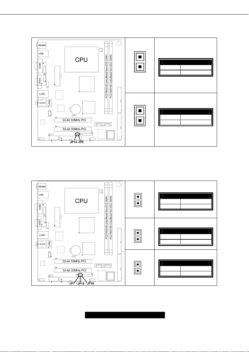
2.9 – LAN1 LED Header (JP8, JP14)
*LAN2 LED Header (*JP7, *JP15, *JP16)
2.10 –
PIN-1
PIN-2
PIN-1
PIN-2
PIN-1
PIN-2
JP8: LAN1 LED HDR
PIN 1
PIN 2
+3.3VSUS
Active
JP14: LAN1 LED HDR
PIN 1
PIN 2
+3.3VSUS
Link 100
*JP7: LAN2 LED HDR
PIN 1
PIN 2
+3.3VSUS
Active
PIN-1
PIN-2
PIN-1
PIN-2
*JP15: LAN2 LED HDR
PIN 1
PIN 2
*JP16: LAN2 LED HDR
PIN 1
PIN 2
+3.3VSUS
Link 100
+3.3VSUS
Link 1000
14
http://www.TYAN.com
Page 15
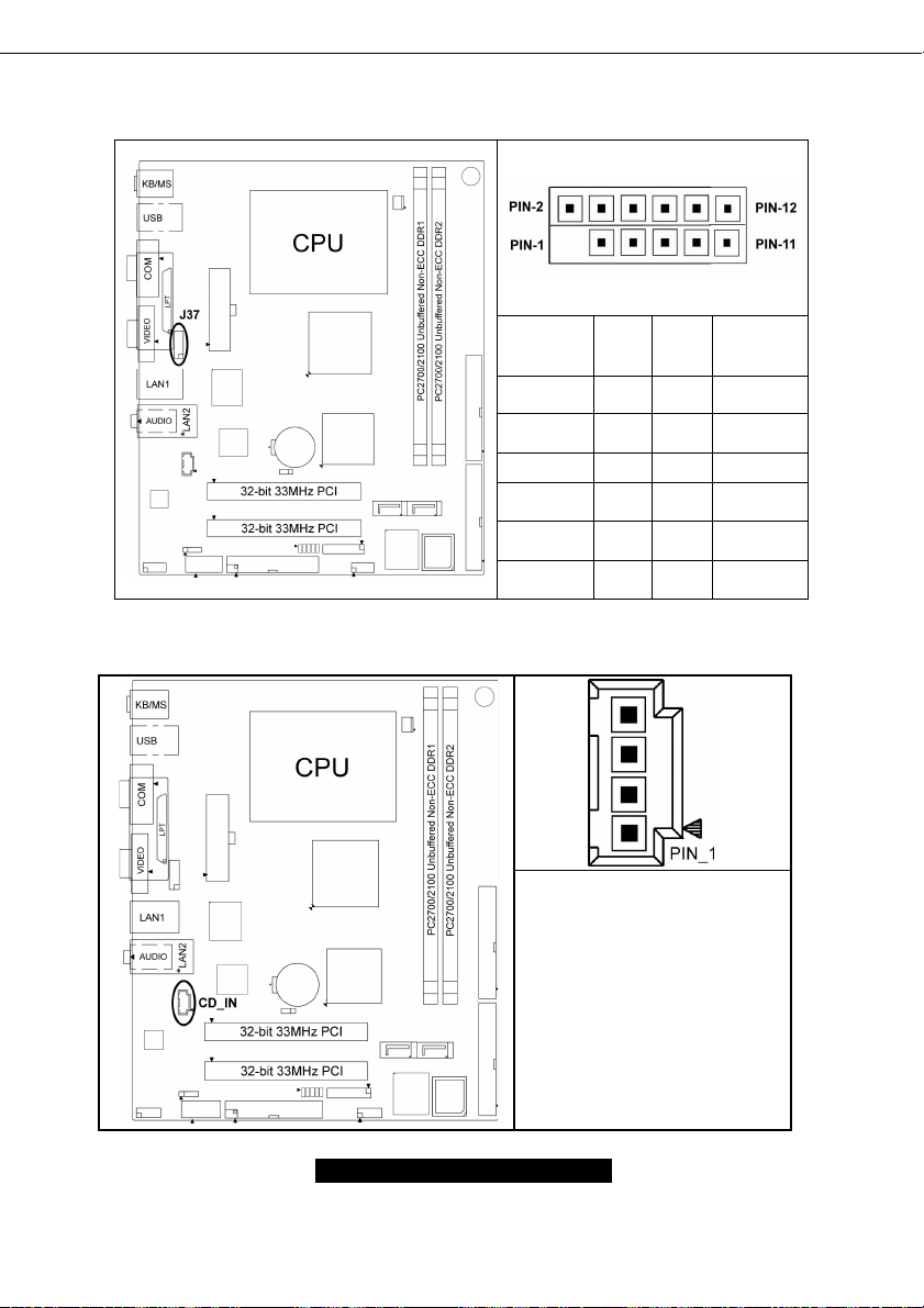
2.11 – VGA Header (J37)
2.12 – Internal Audio Connector (CD_IN)
Signal
Descripti
on
KEY 1 2 GND
Red 3 4 Green
Blue 5 6 GND
+5V CRT 7 8 GND
SDA 9 10 HSY NC
VSYNC 11 12 SCL
Pin # Pin
#
Signal
Descripti
on
Pin4: CD_R
Pin3: GND
Pin2: GND
Pin1: CD_L
15
http://www.TYAN.com
Page 16

2.13 – Mounting the Motherboard
Before installing your motherboard, make sure your chassis has the necessary motherboard
support studs installed. These studs are usually metal and are gold in color. Usually, the chassis
manufacturer will pre-install the support studs. If you’re unsure of stud placement, simply lay the
motherboard inside the chassis and align the screw holes of the motherboard to the studs inside
the case. If there are any studs missing, you will know right away since the motherboard will not
be able to be securely installed.
Some chassis’ include plastic studs instead of metal. Although the plastic studs are usable, TYAN
recommends using metal studs with screws that will fasten the motherboard more securely
in place.
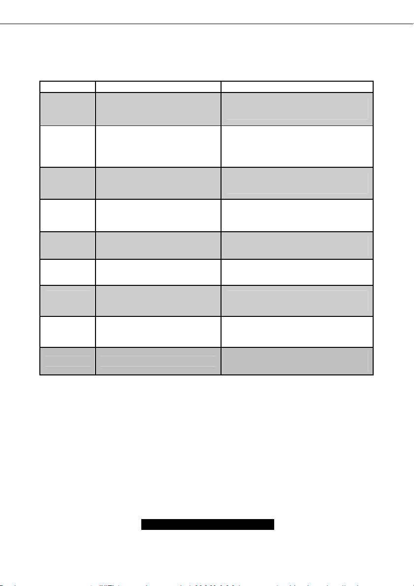
Below is a chart detailing what the most common motherboard studs look like and how they
should be installed.
TIP: Use metal studs if possible, as they hold the motherboard into place more securely than
plastic standoffs.
16
http://www.TYAN.com
Page 17
2.14 – Installing the Memory
Before attempting to install any memory, make sure that the memory you have is compatible with
the motherboard as well as the processor. For example, while PC1600 DDR modules are
compatible with all DDR based motherboards, they will not work if you are required to run the
motherboard and processor buses at 133MHz. For this, PC2100 DDR modules are required.
Critically important is whether you’re using the recommended memory for the current board you
have. For this information, please check TYAN’s web site at: www.TYAN.com
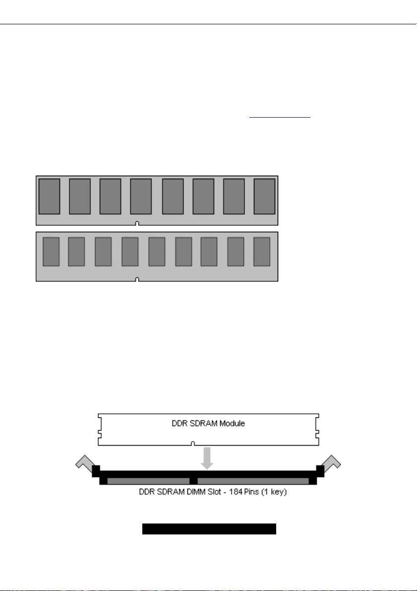
The following diagram shows the types of RAM modules you may encounter.
Use only 184-pin unbuffered non-ECC memory for S2498.
Note: The Tomcat K7M has two DIMM sockets, which supports a maximum of four banks of DDR
memory (only supports 64 MB, 128 MB, 256 MB, 512MB and 1GB technologies for x8 and x16
devices.)
2.15 – Memory Installation Procedure
When you install the memory modules, make sure the module aligns properly with the memory
slot. The modules are keyed to ensure that it is inserted only one way. The method of installing
memory modules are detailed by the following diagrams.
.
Unbuffered
Non-ECC
= 8 Chips
Unbuffered
ECC
= 9 Chips
17
http://www.TYAN.com
Page 18
Once the memory modules are firmly seated in the slot, two latches on either side will close and
secure the module into the slot. Sometimes you may need to close the latches yourself.
To remove the memory module, simply push the latches outwards until the memory module pops
up. Then simply remove the module.
NOTE
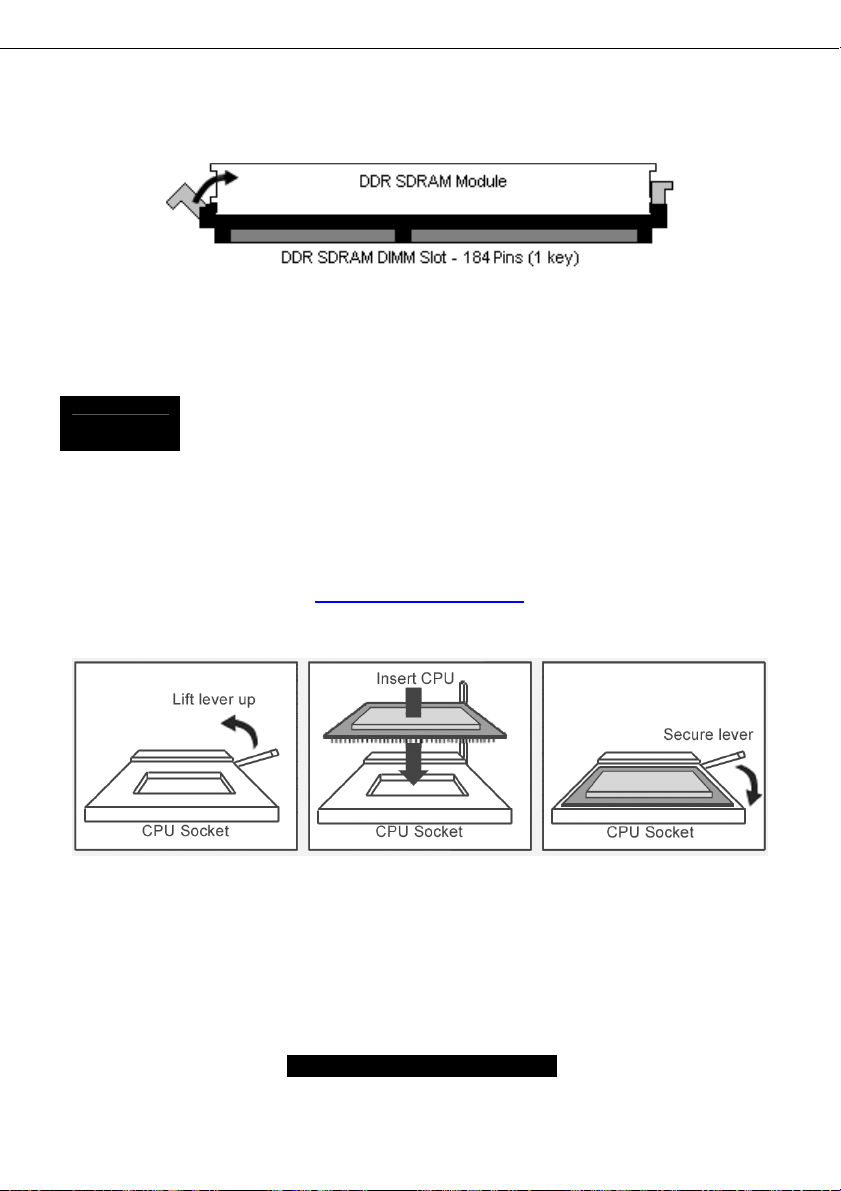
2.16 – Installing the Processor and Heatsink
Your brand new Tomcat K7M supports the latest processor technologies from AMD. Check
TYAN’s website for latest processor support:
Due to the PCI v2.2 specifications, you MUST unplug the power connector to the
motherboard before performing system hardware changes to avoid having your
motherboard boot-up automatically.
http://www.TYAN.com
The following diagrams will detail how to install your processor:
The processor you choose to use may not look exactly like the one pictured above, nor will the
socket look exactly the same. For example, your processor may appear to be in a different color
and have different markings on it. The diagram is provided as a visual guide to help you install the
processor.
1. Lift the lever on the socket until it is approximately 90
socket.
18
o
or as far back as possible to the
http://www.TYAN.com
Page 19
2. Align the processor with the socket. There are keys underneath the processor just like
on memory modules to ensure that they insert the correct way.
3. Seat the processor firmly into the socket by gently pressing down until the processor
sits flush with the socket.
4. Place the socket lever back down until it snaps into place.
5. Your processor is installed.
Take care when installing K7 Geode processors as they have very fragile connector pins
below the processor and can bend and break if inserted improperly.
Heatsink Installation
After you are done installing the processor, you should proceed to installing the heatsink. The
heatsink will ensure that the processor does not overheat, and will continue to operate at
maximum performance. An overheated processor is also dangerous to the long-term reliability of
the motherboard.
Because there are many different types of heatsinks available from many different manufacturers,
many have their own method of installation. For the safest method of installation and information
on choosing the appropriate heatsink, please refer to TYAN’s website: http://www.TYAN.com
Finishing Installing the Heatsink
After you finish installing the heatsink onto the processor and socket, attach the end wire of the
fan (which should already be attached to the heatsink) to the motherboard. The following diagram
illustrates how to connect fans onto the motherboard.
.
After you’re finished installing all the fans you can connect your drives (hard drives, CD-ROM
drives, etc.) to your motherboard.
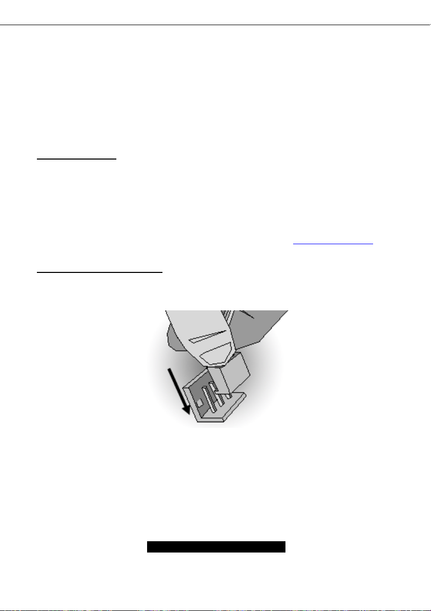
2.17 – Attaching Drive Cables
Attaching IDE cables to your drives is simple because they only go in one way. TYAN
motherboards have two on-board IDE channels for you to use, each supporting two drives. There
is a white and a black IDE connector on your motherboard. The black connector is the Primary
IDE channel and the white connector is the Secondary IDE channel.
Attaching IDE cables to the IDE connectors is illustrated below:
19
http://www.TYAN.com
Page 20

Simply plug in the BLUE END of the IDE cable into the motherboard IDE connector, and the other
ends into the drive(s). Each standard IDE cable has three connectors, two being close to each
other. The BLUE connector that is far on its own is the end that plugs into the motherboard
whereas the other two connectors are used to connect to drives.
TIP: Pin 1 on the IDE cable (usually denoted by a colored wire) faces the drive’s power
connector.
Floppy Drives
Attaching floppy diskette drives are done in a similar manner to hard drives. See the picture below
for an example of a floppy cable. Most of the current floppy drives on the market require that the
cable be installed with the colored stripe positioned next to the power connector. In most cases,
there will be a key pin on the cable which will force a proper connection of the cable.
The first floppy drive (sometimes denoted as
A:) is usually attached to the end of the cable
with the twist in it. Drive B: is usually connected
to the second or third connector in the cable
(the second or third connector after you install
Drive A:).
Refer to your floppy drive’s installation
instructions (if available), or contact your dealer
if you are unsure about how to attach the
floppy drive(s). Remember, you can only have
2 floppy drives connected at any given time.
20
http://www.TYAN.com
Page 21

Below are some symptoms of incorrectly installed floppy drives. While they are minor and
installing them incorrectly doesn’t cause severe problems, it may cause your system to freeze or
crash when trying to read and or write to disks.
Drive is not automatically detected
Drive Fail message at bootup
Drive does not power on
Drive activity light is constantly on
NOTE
Before continuing onto Connecting External Devices, make sure everything is
properly connected. Things like jumpers and case wiring are the most common
causes of troubleshooting frustrations, both for the end-user and for any
company doing technical support.
Symptoms of incorrectly installed floppy drives
Usually caused by faulty cables, cables put in
backwards or a bad floppy drive or
motherboard. Try another floppy drive to verify
the problem if the cable is properly installed or
try replacing the actual cable. Also check to
see if the onboard floppy controller is enabled
in the BIOS setup.
The cable, floppy drive or motherboard may be
faulty. Try another drive or cable to verify.
Check power cable and cabling. Maybe a bad
power supply or drive cable problem.
Usually signifies that the cable on the drive is
on backwards, which is a common issue.
Reverse the cable at the floppy drive end and
try again.
21
http://www.TYAN.com
Page 22

Installing Add-In Cards
2.18 –
Before installing add-in cards, it’s good to be aware if they’re fully compatible with your
motherboard. For this reason, we’ve provided a chart, listing the most common slots that may
appear on your motherboard. Not all the slots in this diagram will be on the same board though,
but there will be combinations. See below for the way the slots look and what each one means.
Simply find the appropriate slot for your expansion card and insert the card in firmly. Do not force
any expansion cards (or anything else) into any slots if they refuse to go in. It’s better to try
another slot or return the faulty card rather than damaging both the motherboard and the card.
TIP: It’s good practice to spread out cards as far apart from each other as possible if you can. This
gives more breathing room and sensitive electronics will cool better and perform more reliably.
NOTE
YOU MUST unplug the power connector to the motherboard before performing
system hardware changes, to avoid having your motherboard boot-up
automatically, due to the PCI v2.2 spec.
22
http://www.TYAN.com
Page 23

2.19 – Connecting External Devices
The standard devices you should expect to plug into the motherboard are keyboards, mice, and
printer cables. The following diagram will detail the ATX port stack for the following board:
Although primarily to connect printers, the parallel printer port is also used for devices such as ZIP
drives, external CD-RW drives, scanners, and other external devices. Serial ports, also known as
COM ports, are primarily used to connect external modems and other RS-232C devices.
TIP: While the ports have been created to accept connectors in only one direction, make sure to
be careful when inserting connectors. At times, attaching connectors in the incorrect orientation
can damage, bend and or break the pins.
2.20 – Installing the Power Supply
There are two power connectors on your Tomcat K7M. By default, the Tomcat K7M requires that
you have an ATX / ATX12V power supply that has a 20-pin and a 4-pin power connector. Do not
use any other type of power supply.
Disconnect power supply from electrical outlet
1. Connect ATX / ATX12V 4-pin power connector.
2. Connect ATX / ATX12V 20-pin power connector.
3. Connect power cable to power supply to power outlet
23
http://www.TYAN.com
Page 24

2.21 – Finishing Up
Congratulations on making it this far! You’re finished setting up the hardware aspect of your
computer. Before closing up your chassis, make sure that all cables and wires are connected
properly, especially IDE cables and most importantly, jumpers. You may have difficulty powering
on your system if the motherboard jumpers are not set correctly.
In the rare circumstance that you have experienced difficulty, even though the instructions herein
were followed, you can find help by asking your vendor for assistance. If they are not available for
assistance, please find setup information and documentation online at our website or by calling
your vendor’s support line.
24
http://www.TYAN.com
Page 25

Chapter 3: BIOS Setup
Installation
The BIOS is the basic input/output system, the firmware on the motherboard that enables your
hardware to interface with your software. This chapter describes different settings for the BIOS
that can be used to configure your system.
The BIOS section of this manual is subject to change without notice and is provided for reference
purposes only. The settings and configurations of the BIOS are current at the time of print, and
therefore may not match exactly what is displayed on screen.
This section describes the BIOS setup program. The setup program lets you modify basic
configuration settings. The settings are then stored in a dedicated, battery-backed memory (called
NVRAM) that retains the information when the power is turned off.
This motherboard’s BIOS is a customized version of the industry-standard BIOS for IBM PC ATcompatible personal computers. The BIOS provides critical, low-level support for the system’s
central processing unit (CPU), memory, and I/O subsystems.
This BIOS has been customized by adding important features such as password protection, power
management, and chipset “tuning” features that control the system. This section will guide you
through the process of configuring the BIOS for your system setup.
Starting Setup
The BIOS is immediately activated when you turn on the computer. The BIOS reads system
configuration in CMOS RAM and begins the process of checking out the system and configuring it
through the Power-On-Self-Test (POST).
When these preliminary tests are complete, the BIOS searches for an operating system on one of
the system’s data storage devices (hard drive, CD-ROM, etc). If one is found, the BIOS will
launch that operating system and hand control over to it. You can enter the BIOS setup by
pressing the [Delete] key when the machine boots up and begins to show the memory count.
Setup Basics
The table below shows how to navigate in the setup program using the keyboard.
Tab Moves from one selection to the next
Left/Right Arrow Keys Change from one menu to the next
Up/Down Arrow Keys More between selections
Enter Opens highlighted section
PgUp/PgDn Keys Change settings.
Key Function
25
http://www.TYAN.com
Page 26

Getting Help
Pressing [F1] will display a small help window that describes the appropriate keys to use and the
possible selections for the highlighted item. To exit the Help Window, press [ESC] or the [F1] key
again.
In Case of Problems
If you discover that you have trouble booting the computer after making and saving the changes
with the BIOS setup program, you can restart the computer by holding the power button down until
the computer shuts off (usually within 4 seconds); resetting by pressing CTRL-ALT-DEL; or
clearing the CMOS.
The best advice is to only alter settings that you thoroughly understand. In particular, do not
change settings in the Chipset section unless you are absolutely sure of the outcome. The
Chipset defaults were carefully chosen by TYAN or your system manufacturer for the best
performance and reliability. Even a seemingly small change to the Chipset setup options may
cause the system to become unstable or unusable.
Setup Variations
Not all systems will have the same BIOS setup layout or options. While the basic look and
function of the BIOS setup remains more or less the same for most systems, the appearance of
your Setup screen may differ from the charts shown in this section. Each system design and
chipset combination requires a custom configuration. In addition, the final appearance of the
Setup program depends on the system designer. Your system designer may decide that certain
items should not be available for user configuration, and remove them from the BIOS setup
program.
NOTE: On the following pages, options written in bold type represent the BIOS Setup default.
26
http://www.TYAN.com
Page 27

3.1 – Main BIOS Setup
When you enter Phoenix - AwardBIOS CMOS Setup Utility, the following screen will appear as
below:
Phoenix – AwardBIOS CMOS Setup Utility
► Standard CMOS Features
► Advanced BIOS Features
► Advanced Chipset Features
► Integrated Peripherals
► Power Management Setup
► PnP/PCI Configurations
► PC Health Status
Esc: Quit ↑ ↓ ← →: Select Item F10: Save & Exit Setup
Time, Date, Hard Disk Type…
Standard CMOS Features
Use this menu for basic system configuration.
Advanced BIOS Features
Use this menu to set the Advanced Features available on your system.
Advanced Chipset Features
Use this menu to change the values in the chipset registers and optimize your system's
performance.
Integrated Peripherals
Use this menu to specify your settings for integrated peripherals.
Power Management Setup
Use this menu to specify your settings for power management.
PnP / PCI Configuration
This entry appears if your system supports PnP / PCI.
PC Health Status
Use this menu to show your system temperature, speed and voltage status.
Frequency/Voltage Control
Use this menu to specify your settings for frequency/voltage control.
Load Fail-Safe Defaults
Use this menu to load the BIOS default values for the minimal/stable performance for your system
to operate.
► Frequency/Voltage Control
Load Fail-Safe Defaults
Load Optimized Defaults
Set Supervisor Password
Set User Password
Save & Exit Setup
Exit Without Saving
27
http://www.TYAN.com
Page 28

Load Optimized Defaults
Use this menu to load the BIOS default values that are factory settings for optimal performance
system operations. While Award has designed the custom BIOS to maximize performance, the
factory has the right to change these defaults to meet their needs.
Supervisor / User Password
Use this menu to set User and Supervisor Passwords.
Save & Exit Setup
Save CMOS value changes to CMOS and exit setup.
Exit Without Save
Abandon all CMOS value changes and exit setup.
28
http://www.TYAN.com
Page 29

3.2 – Standard CMOS Features
In this section, you can alter general features such as the date and time, as well as access to the
IDE configuration options. Note that the options listed below are for options that can directly be
changed within the Main Setup screen. User can Use the arrow keys to highlight the item and
then use the <PgUp> or <PgDn> keys to select the value you want in each item.
Phoenix – AwardBIOS CMOS Setup Utility
Standard CMOS Features
Date (mm: dd: yy)
Time (hh: mm: ss)
►IDE Primary Master
►IDE Primary Slave
►IDE Secondary Master
►IDE Secondary Slave
Drive A
Drive B
Video
Halt On
Based Memory
Extended Memory
Total Memory
↑↓←→: Move
Date / Time Setup:
System Date: Adjusts the system date.
MM Months
DD Days
YYYY Years
System Time: Adjusts the system clock.
HH Hours (24hr. format)
MM Minutes
SS Seconds
IDE Master / Slave Setup:
Computer detects IDE drive type from drive C to drive F.
None / Auto / Manual
Drive A / B:
Defines the floppy drive type.
None / 360K, 5.25in / 1.2M, 5.25in / 720K, 3.5in / 1.44M, 3.5in / 2.88M, 3.5in
Enter: Select
F5: Previous Values
Thu, Apr 3 2003
13: 31: 30
[None]
[None]
[None]
[None]
[1.44M, 3.5 in.]
[None]
[EGA/VGA]
[All Errors]
640K
64512K
65536K
+/-/PU/PD: Value
F6: Fail-Safe Defaults
_________________________
Menu Level ►
Change the day, month, year and
century
F10: Save
29
ESC: Exit
F7: Optimized Defaults
http://www.TYAN.com
Item Help
F1: General Help
Page 30

Video:
Defines video display mode.
EGA/VGA / CGA 40 / CGA 80 / MONO
Halt On:
Determines if the computer should stop when an error is detected during power up.
No Errors / All Errors / All, But Keyboard / All, But Diskette / All, But Disk/Key
30
http://www.TYAN.com
Page 31

3.3 – Advanced BIOS Features
In Advanced BIOS features, you will be able to adjust many of the feature that effect system
speed and boot-up options.
Phoenix – AwardBIOS CMOS Setup Utility
Advanced BIOS Features
Virus Warning
CPU Internal Cache
External Cache
CPU L2 Cache ECC checking
Quick Power On Self Test
►Boot Sequence
Swap Floppy Drive
Boot Up Floppy Seek
Boot Up NumLock Status
Gate A20 Option
Typematic Rate Setting
X Typematic Rate (Chars/Sec)
X Typematic Delay (Msec)
Security Option
APIC Mode
MPS Version Control For OS
OS Select For DRAM > 64MB
Video BIOS Shadow
Small Logo (EPA) Show
↑↓←→: Move
Virus Warning:
This option allows you to choose the VIRUS warning feature for IDE Hard Disk boot sector
protection.
CPU Internal Cache:
Toggles the use of CPU Internal cache.
Enabled / Disabled
External Cache:
This option allows you to enabled or disabled the External Cache.
Enabled / Disabled
CPU L2 Cache ECC Checking:
This option allows you to enabled or disabled the CPU L2 Cache ECC Checking.
Quick Power On Self Test:
This option allows the system to skip self tests for faster startup.
Enter: Select
F5: Previous Values
Enabled / Disabled
Enabled / Disabled
[Disabled]
[Enabled]
[Enabled]
[Enabled]
[Enabled]
[Press Enter]
[Disabled]
[Disabled]
[On]
[Fast]
[Disabled]
6
250
[Setup]
[Disabled]
[1.4]
[Non-OS2]
[Disabled]
[Disabled]
+/-/PU/PD: Value
F6: Fail-Safe Defaults
F10: Save
31
http://www.TYAN.com
________________________
Menu Level ►
Allow you to choose the
VIRUS warning feature for
IDE Hard Disk boot sector
protection. If this function is
enabled and someone attempt
to write data into this area,
BIOS will show a warning
message on screen and alarm
beep
ESC: Exit
F7: Optimized Defaults
Item Help
_
F1: General Help
Page 32

Enabled / Disabled
Swap Floppy Drive:
This option allows the system to swap floppy drive.
Disabled / Enabled
Boot Up Floppy Seek:
This option allows the system to seek floppy drive when boots up.
Enabled / Disabled
Boot Up NumLock Status:
This option allows you to select power on state for NumLock.
Off / On
Gate A20 Option:
Select if chipset or keyboard controller should control GateA20. When set to Fast, the system
chipset controls Gate A20. When set to Normal, a pin in the keyboard controller controls Gate
A20. Setting Gate A20 to Fast improves system speed, particularly with OS/2 and Windows.
Normal / Fast
Typematic Rate Setting:
Toggles control of keyboard key repeat rate.
Enabled/Disable
Typematic Rate (Chars/Sec):
Defines how many characters are repeated per second when holding down a key on the
keyboard.
6 / 8 / 10 / 12 / 15 / 20 / 24 / 30
Typematic Delay (Msec):
Defines the delay that occurs at keystroke before that key will start to repeat.
250 / 500 / 750/ 1000
Security Option:
Sets the password on either just the BIOS setup or the entire system (BIOS setup included).
Setup / System
APIC Mode:
This option allows you to enabled or disabled Advanced Programmable Interrupt Controller
(APIC) Mode.
Enabled / Disabled
MPS Version Control For OS:
Selects APIC mode depending on operating system: select 1.1 for Win NT 3.52, and 1.4 for
Win NT4.0, Win2000 and WinXP
1.4 / 1.1
OS Select For DRAM > 64MB:
Select OS2 only if you are running OS/2 operating system with more than 64MB of RAM.
Non-OS2 / OS2
Video BIOS Shadow:
This option allows you to enabled copies Video BIOS to shadow RAM Improves performance.
32
http://www.TYAN.com
Page 33

Small Logo (EPA) Show:
Toggles the display of the EPA Energy Star logo at POST.
Enabled / Disabled
Boot Sequence:
Disabled / Enabled
Phoenix – AwardBIOS CMOS Setup Utility
►Hard Disk Boot Priority
First Boot Device
Second Boot Device
Third Boot Device
Boot Other Device
Advanced BIOS Features
[Press Enter]
[Floppy]
[CDROM]
[Hard Disk]
[Enabled]
Item Help
Menu Level ►►
Select Your Boot
Device Priority
↑↓←→: Move
Hard Disk Boot Priority:
Select 〔Press Enter〕to set Hard Disk Boot Priority
First / Second / Third Boot Device:
This BIOS attempts to load the operating system from the devices in the sequence selected in
these item.
Boot Other Device:
System can load the operating system from the other devices except above devices
Enabled / Disabled
Enter: Select
F5: Previous Values
Floppy / LS120 / Hard Disk / CDROM / ZIP100 / USB-FDD / USB-ZIP /
USB-CDROM / LAN / Disabled
+/-/PU/PD: Value
F6: Fail-Safe Defaults
33
F10: Save
ESC: Exit
F7: Optimized Defaults
F1: General Help
http://www.TYAN.com
Page 34

3.4 – Advanced Chipsets Features
In Advanced Chipset Features, you will be abled to adjust many of the chipset special features.
Phoenix – AwardBIOS CMOS Setup Utility
Advanced Chipset Features
►DRAM Clock/Drive Control
►AGP & P2P Bridge Control
►CPU & PCI Bus Control
Memory Hole
System BIOS Cacheable
Video RAM Cacheable
↑↓←→: Move
Memory Hole:
Reserve 15-16M Memory for ISA use.
Disabled / Enabled
System BIOS Cacheable:
Selecting Enabled allows caching of the system BIOS ROM at F0000h-FFFFFh, resulting in
better system performance. However, if any program writes to this memory area, a system
error may result.
Disabled / Enabled
VIDEO RAM Cacheable:
Selecting Enabled allows caching of the video RAM, resulting in better system performance.
However, if any program writes to this memory area, a system error may result.
Disabled / Enabled
Enter: Select
F5: Previous Values
[Press Enter]
[Press Enter]
[Press Enter]
[Disabled]
[Disabled]
[Disabled]
+/-/PU/PD: Value
F6: Fail-Safe Defaults
_________________________
F10: Save
F7: Optimized Defaults
ESC: Exit
Item Help
Menu Level ►
F1: General Help
34
http://www.TYAN.com
Page 35

Phoenix – AwardBIOS CMOS Setup Utility
DRAM Clock/Drive Control
Current FSB Frequency
Current DRAM Frequency
DRAM Clock
DRAM Timing
DRAM CAS Latency
Bank Interleave
Precharge to Active (Trp)
Tras Non-DDR400/DDR400
Active to CMD (Trcd)
DRAM Command Rate
DRAM Burst Len
Write Recovery Time
↑↓←→: Move Enter: Select
F5: Previous Values
Current FSB Frequency:
Show current FSB frequency
Current DRAM Frequency:
Show current DRAM frequency
DRAM Clock:
Select setting for DRAM clock
By SPD / 133 MHZ / 166 MHZ / 200 MHZ
DRAM Timing :
Select setting for SDRAM timing
Manual / AUTO By SPD / Turbo / Ultra
DRAM CAS Latency:
This setting defines the number of cycles after a read command until output starts.
1.5/ 2 / 2.5 / 3
Bank Interleave:
Select Bank Interleave
Disabled / 2 Bank / 4 Bank
Precharge to Active (Trp):
This item controls the number of DRAM clocks used for DRAM Trp parameters.
2T / 3T / 4T / 5T
Tras Non-DDR400/DDR400:
[133MHz]
[166MHz]
[By SPD]
[Auto By SPD]
[2.5]
[Disabled]
[4T]
[7T/10T]
[5T]
[2T Command]
[4]
[2T]
+/-/PU/PD: Value
F6: Fail-Safe Defaults
F10: Save ESC: Exit
F7: Optimized Defaults
35
_________________________
Item Help
Menu Level ►
F1: General Help
http://www.TYAN.com
Page 36

This item controls the number of DRAM clocks used for DRAM Tras parameters.
6T/8T / 7T /10T / 5T/6T / 8T/12T
Active to CMD (Trcd):
This item controls the number of DRAM clocks used for DRAM Trcd parameters.
2T / 3T / 4T / 5T
DRAM Command Rate:
This item selects DRAM command rate parameters.
2T Command / 1T Command
DRAM Burst Len:
This item selects DRAM burst length parameters.
4 / 8
Write Recovery Time:
This item selects Write Recovery Time parameters.
2T / 3T
Phoenix – AwardBIOS CMOS Setup Utility
AGP & P2P Bridge Control
AGP Aperture Size
AGP Mode
AGP Fast Write
AGP Master 1 WS Write
AGP Master 1 WS Read
AGP 3.0 Calibration Cycle
VGA Share Memory Size
CPU Direct Access FB
Select Display Device
Panel Type
TV_type
TV_Connector
TV_Layout
Dithering
↑↓←→: Move Enter: Select +/-/PU/PD: Value F10: Save ESC: Exit F1: General Help
F5: Previous Values
AGP Aperture Size:
Decide How many memory AGP can use as frame buffer.
256M/128M/64M/32M/16M/8M/4M/1G/512M
AGP Mode :
Decide AGP Translation speed
1X/2X/4X
[64M]
[4X]
[Disabled]
[Disabled]
[Disabled]
[Enabled]
[64M]
[Enabled]
[CRT]
[7]
[NTSC]
[CVBS]
[Default]
[Disabled]
F6: Fail-Safe Defaults
_________________________
F7: Optimized Defaults
36
Item Help
Menu Level ►
http://www.TYAN.com
Page 37

AGP Fast Write:
Write to frame buffer directly
Disabled/Enabled
AGP Master 1 WS Write:
Enable / Disable AGP Master 1 WS Write function
Disabled/Enabled
AGP Master 1 WS Read:
Enable / Disable AGP Master 1 WS Read function
Disabled/Enabled
AGP 3.0 Calibration Cycle:
Enable / Disable AGP 3.0 Calibration Cycle
Disabled/Enabled
CPU Direct Access FB:
Enable / Disable CPU Direct Access FB
Disabled/Enabled
Select Display Device:
Select Display Device type
CRT / LCD / CRT+LCD / TV / CRT+TV / LCD+TV / DVI / CRT+DVI / TV+DVI
Panel Type:
Show panel type
TV_type:
Select TV type
NTSC / PAL / PALM / PALN / PALNc
TV_Connector:
Select TV connector type
CVBS / S-Video 0 / R/G/B / Cr/Y/Cb / SDTV-R/G/B / SDTV-Pr/Y/Pb / S-Video 1
TV_Layout:
Select TV layout value
Default / COMP.+S-Video / S-Video+S-Video / COMP.+R/G/B / COMP.+Y/Cb/Cr
/ COMP.+SDTV-R,G,B / COMP.+SDTV-Y,Pb,Pr
Dithering:
Enable / Disable Dithering
Disabled/Enabled
37
http://www.TYAN.com
Page 38

Phoenix – AwardBIOS CMOS Setup Utility
CPU & PCI Bus Control
PCI1 Master 0 WS Write
PCI2 Master 0 WS Write
PCI1 Post Write
PCI2 Post Write
VLink 8X Support
PCI Delay Transaction
↑↓←→: Move Enter: Select +/-/PU/PD: Value F10: Save ESC: Exit F1: General Help
PCI1/PCI2 Master 0 WS Write:
Enable / Disable PCI1/2 Master 0 WS function
Enable / Disable
PCI1/PCI2 Post Write:
Enable / Disable PCI1/2 post write function
Enable / Disable
VLink 8X Support:
Enable / Disable chip VLink 8X WS function
Enable / Disable
PCI Delay Transaction:
Enable / Disable Chip PCI Delay function
Enable / Disable
F5: Previous Values
[Enabled]
[Enabled]
[Enabled]
[Enabled]
[Enabled]
[Enabled]
F6: Fail-Safe Defaults
_________________________
F7: Optimized Defaults
Item Help
Menu Level ►
38
http://www.TYAN.com
Page 39

3.5 – Integrated Peripherals
Options related to onboard peripheral features can be altered through the following:
Phoenix – AwardBIOS CMOS Setup Utility
Integrated Peripherals
► VIA OnChip IDE Device
► VIA OnChip PCI Device
► SuperIO Device
Init Display First
↑↓←→: Move Enter: Select
Init Display First:
This item selects which display card init first.
PCI Slot / Onboard /AGP
VIA OnChip IDE Device:
OnChip SATA
SATA Mode
OnChip IDE Channel0
OnChip IDE Channel1
IDE Prefetch Mode
Primary Master PIO
Primary Slave PIO
Secondary Master PIO
Secondary Slave PIO
Primary Master UDMA
Primary Slave UDMA
Secondary Master UDMA
Secondary Slave UDMA
IDE HDD Block Mode
↑↓←→: Move Enter: Select +/-/PU/PD: Value F10: Save ESC: Exit
OnChip SATA:
The integrated peripheral controller contains a SATA interface with support for two SATA
channels. Select “Auto” to activate each channel separately.
F5: Previous Values
Phoenix – AwardBIOS CMOS Setup Utility
F5: Previous Values
[Press Enter]
[Press Enter]
[Press Enter]
[PCI Slot]
+/-/PU/PD: Value
F6: Fail-Safe Defaults
VIA OnChip IDE Device
[Enabled]
[IDE]
[Enabled]
[Enabled]
[Enabled]
[Auto]
[Auto]
[Auto]
[Auto]
[Auto]
[Auto]
[Auto]
[Auto]
[Enabled]
F6: Fail-Safe Defaults
http://www.TYAN.com
39
_________________________
F10: Save
ESC: Exit
F7: Optimized Defaults
_________________________
F7: Optimized Defaults
Item Help
Menu Level ►
F1: General Help
Item Help
Menu Level ►►
F1: General Help
Page 40

Disabled /Enabled
SATA Mode:
Select SATA mode
Raid /IDE
OnChip IDE Channel 0/1 :
The integrated peripheral controller contains an IDE interface with support for two IDE
channels. Select “Enabled” to activate each channel separately.
Disabled /Enabled
IDE Prefetch Mode:
Select Disabled Or Enabled IDE Prefetch Mode
Disabled / Enabled
Primary / Secondary Master/ Slave PIO:
The four IDE PIO (Programmed Input / Output) field let you set a PIO mode (0-4) for each of
the four IDE devices that the onboard IDE interface supports. Modes 0 through 4 provide
successively increased performance. In Auto mode, the system automatically determines the
best mode for each device.
Auto / Mode 0 / Mode 1 / Mode 2 / Mode 3 / Mode 4
Primary / Secondary Master/ Slave UDMA:
This allows you to select the mode of operation for the Ultra DMA/33 implementation is
possible only if your IDE hard drive supports it and the operating environment includes a DMA
driver (Windows 95 OSR2 or a third-party IDE bus master driver). If your hard drive and your
system software both support Ultra DMA/33, select Auto to enable bios SUPPORT.
Auto / Disabled
IDE HDD Block Mode:
Select Disabled Or Enabled IDE HDD Block Mode
Enabled / Disabled
VIA OnChip PCI Device:
Phoenix – AwardBIOS CMOS Setup Utility
VIA OnChip PCI Device
AC97 Audio
MC97 Modem
OnChip USB Controller
OnChip EHCI Controller
USB Keyboard Support
USB Mouse Support
↑↓←→: Move Enter: Select +/-/PU/PD: Value
F5: Previous Values
[AUTO]
[AUTO]
[All Enabled]
[Enabled]
[Disabled]
[Disabled]
F6: Fail-Safe Defaults
F10: Save ESC: Exit
40
_________________________
Menu Level ►►
F7: Optimized Defaults
Item Help
F1: General Help
http://www.TYAN.com
Page 41

AC97 Audio:
Enable / Disable onchip AC97.audio
Auto / Disabled
MC97 Modem:
Enable / Disable onchip MC97. Modem
Auto / Disabled
Onchip USB Controller:
This item allows you to decide to “All Disabled” or “All Enabled” the USB device.
All Disabled / All Enabled / 1&2 USB Port / 2&3 USB Port / 1&3 USB Port / 1 USB
OnChip EHCI Controller:
This item allows you to decide to “Enabled” or “Disabled” the EHCI device.
Enabled / Disabled
USB Keyboard Support:
Select “Enabled” if your system contains a USB controller and you have a USB keyboard.
Enabled / Disabled
USB Mouse Support:
Select “Enabled” if your system contains a USB controller and you have a USB mouse.
Enabled / Disabled
Port/ 2 USB Port / 3 USB Port
41
http://www.TYAN.com
Page 42

Super IO Device:
Phoenix – AwardBIOS CMOS Setup Utility
Super IO Device
Onboard FDC Controller
Onboard Serial Port 1
Onboard Serial Port 2
UART Mode Select
RxD, TxD Active
IR Transmission Delay
UR2 Duplex Mode
Use IR Pins
Onboard Parallel Port
Parallel Port Mode
EPP Mode Select
ECP Mode Use DMA
Game Port Address
Midi Port Address
Midi Port IRQ
↑↓←→: Move Enter: Select +/-/PU/PD: Value F10: Save ESC: Exit
F5: Previous Values
Onboard FDC Controller:
Select Enabled if your system has a floppy disk controller (FDC) installed on the system board
and you wish to use it. If you install and-in FDC or the system has no floppy drive, select
“Disabled” in the field.
Enabled / Disabled
Onboard Serial Port 1 / 2:
Select an address and corresponding interrupt for the first and second serial ports.
3F8/IRQ4 / 2E8/IRQ3 / 3E8/IRQ4 / 2F8/IRQ3 / Disabled / Auto
UART Mode Select:
This field allows the users to configure what IR mode the 2nd serial port should use.
Normal / IrDA and ASKIR
RxD, TxD Active:
This field configures the receive and transmit signals generated from the IR port.
Hi, Hi / Hi, Lo / Lo, Hi / Lo, Lo
IR Transmission Delay:
This item allows you to “Enabled” or Disabled” the IR transmission delay.
Enabled / Disabled
UR2 Duplex Mode:
This item allows you to select IR “Half” or “Full” duplex function.
[Enabled]
[3F8 / IRQ4]
[2F8 / IRQ3]
[Normal]
[Hi, Lo]
[Enabled]
[Half]
IR-Rx2Tx2
[378 / IRQ7]
[SPP]
[EPP1.7]
[3]
[201]
[330]
[10]
F6: Fail-Safe Defaults
_________________________
Menu Level ►►
F7: Optimized Defaults
42
Item Help
F1: General Help
http://www.TYAN.com
Page 43

Half / Full
Use IR Pins:
This item allows the user to configure the IR Pins: IR-Rx2Tx2 .
Onboard Parallel Port:
This field allows the user to configure the LPT port.
378/IRQ7 / 278/IRQ5 / 3BC/IRQ7 / Disabled
Parallel Port Mode:
This field allows the user to select the parallel port mode.
SPP / EPP / ECP / ECP+EPP/ Normal
EPP Mode Select:
This item allows you to determine the IR transfer mode of onboard I/O chip.
EPP1.9 / EPP1.7
ECP Mode Use DMA:
This field allows the user to select the DMA1 or DMA3 for the ECP mode.
1 / 3
Game Port Address:
This field allows the user to configure the Game port.
Disabled / 201 / 209
Midi Port Address:
This field allows the user to configure the Midi port.
Disabled / 330 / 300 / 290
Midi Port IRQ:
This field allows the user to configure the Midi port IRQ.
5 / 10
43
http://www.TYAN.com
Page 44

3.6 – Power Management Setup
Options related to power management can be altered through the following:
Phoenix – AwardBIOS CMOS Setup Utility
Power Management Setup
ACPI Function
ACPI Suspend Type
Power Management Option
HDD Power Down
Suspend Mode
Video Off Option
Video Off Method
MODEN Use IRQ
Soft-Off by PWRBTN
Run VGABOIS if S3 Resume
Ac Loss Auto Restart
►IRQ/Event Activity Detect
↑↓←→: Move Enter: Select +/-/PU/PD: Value F10: Save
ACPI Function:
Toggles advanced power and configuration done by OS.
Enabled / Disabled
ACPI Suspend Type:
Defines ACPI system suspend mode.
S1 (POS)/ S3 (STR)/ S1&S3
Power Management Option:
Defines the type of power saving features the system should follow.
User Define / Maximum Saving / Minimum Saving
HDD Power Down:
Defines hard drive power down delay.
Disabled / 1 min-15 min
Suspend Mode:
Defines the method used to power off the system.
Disabled / 1 Min / 2 Min / 4 Min / 6 Min / 8 Min / 10 Min / 20 Min / 30Min / 40Min / 1 Hour
Video Off Method:
Defines the method used to power off graphics.
V/H SYNC+Blank / Blank / DPMS
Video Off Option:
Tell you what time frame that the video will be disabled under current power management settings.
Always On / Suspend -> Off
F5: Previous Values
[Enabled]
[S1 (POS)]
[User Define]
[Disabled]
[Disabled]
[Suspent -> Off]
[V/H SYNC+Blank]
[3]
[Instand-Off]
[Auto]
[Off]
[Press Enter]
F6: Fail-Safe Defaults
http://www.TYAN.com
44
_________________________
F7: Optimized Defaults
Item Help
Menu Level ►
ESC: Exit F1: General Help
Page 45

MODEM Use IRQ:
Name the interrupt request (IRQ) line assigned to the modem (if any) on your system. Activity of
the selected IRQ always awakens the system.
NA / 3 / 4 / 5 / 7 / 9 / 10 / 11
Soft-Off by PWRBTN:
Defines the mode of the Soft-Off by PWRBTN.
Run VGABOIS if S3 Resume:
Defines the type used to run VGABOIS if S3 Resume.
Ac Loss Auto Restart:
Defines the type of the Ac Loss Auto Restart.
PS2KB Wakeup Select:
When Select password, Please press ENTER key to change Password Max 8 numbers.
PS2KB Wakeup From S3/S4/S5:
Defines the mode of the PS2KB Wakeup From S3/S4/S5:
PS2MS Wakeup from S3/S4/S5:
Defines whether PS2 Mouse can wake the system from S3/S4/S5.
Delay 4 Sec /Instant-Off
Auto / Yes / No
Off / On
Phoenix – AwardBIOS CMOS Setup Utility
IRQ/Event Activity Detect
PS2KB Wakeup Select
PS2KB Wakeup From S3/S4/S5
PS2MS Wakeup from S3/S4/S5
USB Resume from S3
VGA
LPT & COM
HDD & FDD
PCI Master
PowerOn by PCI Card
Modem Ring Resume
RTC Alarm Resume
Date (of Month)
Resume Time (hh:mm:ss)
►IRQs Activity Monitoring
↑↓←→: Move
Disable / Ctrl+F1 / Ctrl+F2……
Enter: Select +/-/PU/PD: Value F10: Save ESC: Exit F1: General Help
F5: Previous Values
[Hot Key]
[Disabled]
[Disabled]
[Disabled]
[OFF]
[LPT/COM]
[ON]
[OFF]
[Disabled]
[Disabled]
[Disabled]
0
0: 0: 0
[Press Enter]
F6: Fail-Safe Defaults
45
_________________________
F7: Optimized Defaults
Item Help
Menu Level ►►
http://www.TYAN.com
Page 46

USB Resume from S3:
Defines whether the USB can Resume system from S3.
VGA:
Defines whether to On or Off VGA.
LPT & COM:
Defines which to choose from LPT and COM,
HDD & FDD:
Defines the status of HDD & FDD.
PCI Master:
Defines the status of PCI Master.
PowerOn by PCI Card:
Defines whether PCI card can wake up system or not:
Modem Ring Resume:
Defines whether the system will resume if the modem is dialed into.
RTC Alarm Resume:
Defines whether the system will wake up if the RTC Alarm come out.
Date(of Month):
This item is set to 0.
Disabled / Enabled
Disabled / Enabled
Off / On
NONE / LPT / COM / LPT/COM
Off / On
Off / On
Disabled / Enabled
Disabled / Enabled
Disabled / Enabled
46
http://www.TYAN.com
Page 47

Phoenix – AwardBIOS CMOS Setup Utility
IRQs Activity Monitoring
Primary INTR
IRQ3 (COM 2)
IRQ4 (COM 1)
IRQ5 (LPT 2)
IRQ6 (Floppy Disk)
IRQ7 (LPT 1)
IRQ8 (RTC Alarm)
IRQ9 (IRQ2 Redir)
IRQ10 (Reserved)
IRQ11 (Reserved)
IRQ12 (PS/2 Mouse)
IRQ13 (Coprocessor)
IRQ14 (Hard Disk)
IRQ15 (Reserved)
↑↓←→: Move Enter: Select +/-/PU/PD: Value F10: Save
Primary INTR:
Defines the status of the Primary INTR.
Off / On
IRQ8, 9, 10, 11, 15:
Set these items as follow.
Disabled / Enabled
IRQ3,4, 5, 6, 7, 12, 13, 14:
Set these items as follow.
Disabled / Enabled
F5: Previous Values
[ON]
[Enabled]
[Enabled]
[Enabled]
[Enabled]
[Enabled]
[Disabled]
[Disabled]
[Disabled]
[Disabled]
[Enabled]
[Enabled]
[Enabled]
[Disabled]
F6: Fail-Safe Defaults
47
http://www.TYAN.com
_________________________
ESC: Exit
F7: Optimized Defaults
Item Help
Menu Level ►►►
F1: General Help
Page 48

3.7 – PnP/PCI Configurations
Options related to all the configurations of PnP / PCI resources.
Phoenix – AwardBIOS CMOS Setup Utility
PnP / PCI Configurations
PNP OS Installed
Reset Configuration Data
Resources Controlled By
X IRQ Resources
PCI / VGA Palette Snoop
Assign IRQ For VGA
Assign IRQ For USB
[No]
[Disabled]
[Auto (ESCD)]
Press Enter
[Disabled]
[Enabled]
[Enabled]
Item Help
_________________________
Menu Level ►
Default is Disabled.
Select Enabled to
Reset Extended System
Configuration Data
ESCD> when you exit
Setup if you have
Installed a new add-on
and the system
reconfiguration has
caused such a serious
conflict that the OS
cannot boot
↑↓←→: Move Enter: Select +/-/PU/PD: Value F10: Save ESC: Exit
F5: Previous Values
PNP OS Installed:
Select Yes if you are using a Plug and Play capable operating System. Select No if you need the
BIOS to configure non-boot devices.
No /Yes
Reset Configuration Data:
This setting allow you to clear ESCD data.
Enabled / Disabled
Resources Controlled By:
Default whether system resources are controller by BIOS or by user.
Manual / Auto (ESCD)
PCI / VGA Palette Snoop:
Leave as default.
Enabled / Disabled
IRQ Resources:
Press Enter.
Assign IRQ For VGA and USB:
Set as follow:
Disabled / Enabled
F6: Fail-Safe Defaults
48
F7: Optimized Defaults
F1: General Help
http://www.TYAN.com
Page 49

3.8 – PC Health Status
This menu is related to detecting system temperature, voltage, fan and speed.
Phoenix – AwardBIOS CMOS Setup Utility
PC Health Status
CPU Warning Temperature
Current SYS Temperature
Current CPU Temperature
Current CPUFAN Speed
Current SYSFAN Speed
VCORE
+3.3 V
+5 V
+12 V
-12 V
Shutdown Temperature
↑↓←→: Move Enter: Select +/-/PU/PD: Value F10: Save ESC: Exit F1: General Help
F5: Previous Values
CPU Warning Temperature:
Set the CPU Warning Temperature.
Disabled / 50C/122F / 53C/127F / 56C/133F / 60C/140F / 63C/145F / 66C/151F
/ 70C/158F
Shutdown Temperature: /
set the Shutdown Temperature.
Disabled / 60C/140F / 65C/149F / 70C/158F / 75C/167F
Note: The onboard Winbond® 83697HF hardware monitoring ASIC automatically detects the
system, motherboard and CPU temperature. The hardware monitor ASIC also detects the voltage
output through the voltage regulators.
[Disabled]
[Disabled]
F6: Fail-Safe Defaults
_________________________
F7: Optimized Defaults
Item Help
Menu Level ►
49
http://www.TYAN.com
Page 50

3.9 – Frequency/Voltage Control
Options related to control CPU clock and frequency ratio.
Phoenix – AwardBIOS CMOS Setup Utility
Frequency / Voltage Control
Auto Detect PCI Clk
.
Spread Spectrum
CPU Clock
[Enabled]
[Disabled]
[ 100 ]
_________________________
↑↓←→: Move Enter: Select +/-/PU/PD: Value F10: Save ESC: Exit
F5: Previous Values
F6: Fail-Safe Defaults
F7: Optimized Defaults
Auto Detect PCI Clk:
Sets the BIOS to automatically adjust PCI and memory bus speeds accordingly.
Enabled / Disabled
Spread Spectrum:
Reduces interference on the motherboard. Leave as default if your system works correctly.
Enabled / Disabled
CPU Clock:
Show the CPU clock.
50
http://www.TYAN.com
Item Help
Menu Level ►
F1: General Help
Page 51

3.10 – Load Fail-Safe Defaults
Phoenix – AwardBIOS CMOS Setup Utility
► Standard CMOS Features
► Advanced BIOS Features
► Advanced Chipset Features
► Integrated Peripherals
► Power Management Setup
► PnP/PCI Configurations
► PC Health Status
Esc: Quit ↑ ↓ ← →: Select Item
When you press <Enter> on this item you get a confirmation dialog box with a message similar to:
Pressing ‘Y’ loads the BIOS default values for the most stable, minimal-performance system
Load Fail-Safe Defaults (Y/N)? N
F10: Save & Exit Setup
Load Fail-Safe Defaults
Load Fail-Safe Defaults (Y/N)? N
► Frequency/Voltage Control
Load Fail-Safe Defaults
Load Optimized Defaults
Set Supervisor Password
Set User Password
Save & Exit Setup
Exit Without Saving
operations.
3.11 – Load Optimized Defaults
Phoenix – AwardBIOS CMOS Setup Utility
► Standard CMOS Features
► Advanced BIOS Features
► Advanced Chipset Features
► Integrated Peripherals
► Power Management Setup
► PnP/PCI Configurations
► PC Health Status
Esc: Quit ↑ ↓ ← →: Select Item
When you press <Enter> on this item you get a confirmation dialog box with a message similar to:
Pressing ‘Y’ loads the default values that are factory settings for optimal performance system
Load Optimized Defaults (Y/N)? N
F10: Save & Exit Setup
Load Optimized Defaults
Load Optimized Defaults (Y/N)? N
► Frequency/Voltage Control
Load Fail-Safe Defaults
Load Optimized Defaults
Set Supervisor Password
Set User Password
Save & Exit Setup
Exit Without Saving
operations.
51
http://www.TYAN.com
Page 52

3.12 – Supervisor/User Password Setting
► Standard CMOS Features
► Advanced BIOS Features
► Advanced Chipset Features
► Integrated Peripherals
► Power Management Setup
► PnP/PCI Configurations
► PC Health Status
Esc: Quit ↑ ↓ ← →: Select Item
You can set either a supervisor or a user password, or both of them. The differences are:
Set Supervisor Password: can enter and change the options of the setup menus.
Set User Password: Can enter but does not have permission to change any options.
When you select this function, the following message will appear at the center of the screen to
assist you in creating a password.
ENTER PASSWORD:
► Standard CMOS Features
► Advanced BIOS Features
► Advanced Chipset Features
► Integrated Peripherals
► Power Management Setup
► PnP/PCI Configurations
► PC Health Status
Esc: Quit ↑ ↓ ← →: Select Item
Phoenix – AwardBIOS CMOS Setup Utility
► Frequency/Voltage Control
Load Fail-Safe Defaults
Load Optimized Defaults
Set Supervisor Password
Enter Password:
F10: Save & Exit Setup
Change/Set/Disable Password
Phoenix – AwardBIOS CMOS Setup Utility
Enter Password:
F10: Save & Exit Setup
Change/Set/Disable Password
Set User Password
Save & Exit Setup
Exit Without Saving
► Frequency/Voltage Control
Load Fail-Safe Defaults
Load Optimized Defaults
Set Supervisor Password
Set User Password
Save & Exit Setup
Exit Without Saving
52
http://www.TYAN.com
Page 53

Type the password, up to eight characters in length, and press <Enter>. The password typed now
will clear any previously entered password from CMOS memory. You will be asked to confirm the
password. Type the password again and press <Enter>. You may also press <Esc> to abort the
selection and not enter a password.
To disable a password, just press <Enter> when you are prompted to enter the password. A
message will confirm the password will be disabled. Once the password is disabled, the system
will boot and you can enter Setup freely.
PASSWORD DISABLED.
When a password has been enabled, you will be prompted to enter it every time you try to enter
Setup. This prevents an unauthorized person from changing any part of your system
configuration.
Additionally, when a password is enabled, you can also require the BIOS to request a password
every time your system is rebooted. This would prevent unauthorized use of your computer.
You determine when the password is required within the BIOS Features Setup Menu and its
Security option (see Section 3). If the Security option is set to “System”, the password will be
required both at boot and at entry to Setup. If set to “Setup”, prompting only occurs when trying to
enter Setup.
3.13 – Exit Selecting
► Standard CMOS Features
► Advanced BIOS Features
► Advanced Chipset Features
► Integrated Peripherals
► Power Management Setup
► PnP/PCI Configurations
► PC Health Status
Esc: Quit ↑ ↓ ← →: Select Item
Save & Exit Setup
Pressing <Enter> on this item asks for confirmation:
Pressing “Y” stores the selections made in the menus in CMOS – a special section of memory that
stays on after you turn your system off. The next time you boot your computer, the BIOS
Phoenix – AwardBIOS CMOS Setup Utility
► Frequency/Voltage Control
Load Fail-Safe Defaults
Load Optimized Defaults
Set Supervisor Password
Set User Password
Enter Password:
F10: Save & Exit Setup
Change/Set/Disable Password
Save to CMOS and EXIT (Y/N)? Y
Save & Exit Setup
Exit Without Saving
53
http://www.TYAN.com
Page 54

configures your system according to the Setup selections stored in CMOS. After saving the values
the system is restarted again.
Exit Without Saving
► Standard CMOS Features
► Advanced BIOS Features
► Advanced Chipset Features
► Integrated Peripherals
► Power Management Setup
► PnP/PCI Configurations
► PC Health Status
Esc: Quit ↑ ↓ ← →: Select Item
Pressing <Enter> on this item asks for confirmation:
This allows you to exit Setup without storing in CMOS any change. The previous selections
remain in effect. This exits the Setup utility and restarts your computer.
Phoenix – AwardBIOS CMOS Setup Utility
► Frequency/Voltage Control
Load Fail-Safe Defaults
Load Optimized Defaults
Set Supervisor Password
Set User Password
SAVE to CMOS and EXIT (Y/N)? N
F10: Save & Exit Setup
Save Data to CMOS
Quit without saving (Y/N)? Y
Save & Exit Setup
Exit Without Saving
54
http://www.TYAN.com
Page 55

Chapter 4: Diagnostics
Note: if you experience problems with setting up your system, always check the following things in
the following order:
By checking these items, you will most likely find out what the problem might have been when
setting up your system. For more information on troubleshooting, check the TYAN website at:
http://www.TYAN.com
4.1 Beep Codes
Fatal errors, which halt the boot process, are communicated through a series of audible beeps.
For example, if the BIOS POST can initialize the video but an error occurs, an error message will
be displayed. If it cannot display the message, it will report the error as a series of beeps.
The most common type of error is memory error:
Memory not installed or memory not seated in the socket properly. If this occurs, the board
will beep continuously and will not stop until power off. Please ensure that the correct type
of memory is installed in the correct location.
If you get this error, please check your memory configuration, order, type, and check for faulty
modules. Please check our website for memory compatibility.
Before calling your vendor or calling TYAN Tech Support, be sure that you know how many beeps
your board made, and how long the beeps were. Also have other information such as your
attached add-in cards, drives and OS to help speed up the support process and come to a
possible solution faster.
4.2 Flash Utility
Every BIOS file is unique for the motherboard it was designed for. For Flash Utilities, BIOS
downloads, and information on how to properly use the Flash Utility with your motherboard, you
must check the TYAN website: http://www.TYAN.com/
NOTE
.
Please be aware that by flashing your BIOS, you agree that in the even of a BIOS
flash failure, you must contact your dealer for a replacement BIOS. There are no
exceptions. TYAN does not have a policy of replacing BIOS chips directly with end
users. In no event will TYAN be held responsible for damage done to the BIOS by
the end user.
Memory, Video, CPU
55
http://www.TYAN.com
Page 56

Appendix I: Glossary
ACPI (Advanced Configuration and Power Interface): a power management specification that
allows the operating system to control the amount of power distributed to the computer’s devices.
Devices not in use can be turned off, reducing unnecessary power expenditure.
AGP (Accelerated Graphics Port): an interface specifically designed for the demands of 3D
graphics applications. The 32-bit AGP channel directly links the graphics controller to the system
memory. While the channel runs at just 66MHz, it supports data transmission during both the
rising and falling ends of the clock cycle, yielding an effective speed of 133MHz.
ATAPI (AT Attachment Packet Interface): also known as IDE or ATA; a drive implementation
that includes the disk controller on the device itself. It allows CD-ROMs and tape drives to be
configured as master or slave devices, just like hard drives.
ATX: the form factor designed to replace the AT form factor. It improves on the AT design by
rotating the board 90 degrees, so that the IDE connectors are closer to the drive bays, and the
CPU is closer to the power supply and cooling fan. The keyboard, mouse, USB, serial, and
parallel ports are built-in.
Bandwidth: refers to carrying capacity. The greater the bandwidth, the more data the bus, phone
line, or other electrical path, can carry. Greater bandwidth, then, also results in greater speed.
BBS (BIOS Boot Specification): is a feature within the BIOS that creates, prioritizes, and
maintains a list of all Initial Program Load (IPL) devices, and then stores that list in NVRAM. IPL
devices have the ability to load and execute an O/S, as well as provide the ability to return to the
BIOS if the O/S load process fails for some reason. At that point, the next IPL device is called
upon to attempt loading of the O/S.
BIOS (Basic Input/Output System): the firmware that resides in the ROM chip, and provides the
basic instructions for controlling your computer’s hardware. Both the operating system and
application software use BIOS routines to ensure compatibility.
Buffer: a portion of RAM which is used to temporarily store data, usually from an application,
though it is also used when printing, and in most keyboard drivers. The CPU can manipulate data
in a buffer before copying it, all at once, to a disk drive. While this improves system performance --
- reading to or writing from a disk drive a single time is much faster than doing so repeatedly --there is also the possibility of losing your data should the system crash. Information stored in a
buffer is temporarily stored, not permanently saved.
Bus: a data pathway. The term is commonly used to refer to the connection between the
processor and system memory, and between the processor and AGP, PCI or ISA buses.
Bus mastering: allows peripheral devices and IDE controllers to access the system memory
without going through the CPU (similar to DMA channels).
Cache: a temporary storage area for data that will be needed often by an application. Using a
cache lowers data access times, since the needed information is stored in the SRAM instead of in
the slower DRAM. Note that the cache is also much smaller than your system memory: a typical
cache size is 512KB, while you may have as much as 4GB or more of system memory.
56
http://www.TYAN.com
Page 57

Cache size: refers to the physical size of the cache. This should not be confused with the
cacheable area, which is the total amount of memory which can be scanned by the system in
search of data to put into the cache. A typical setup would be a cache size of 512KB, and a
cacheable area of 512MB. In this case, up to 512KB of system memory is capable of being
cached. However, only 512KB of this memory will be in the cache at any given moment.
Closed and open jumpers: jumpers and jumper pins are active when they are “on” or “closed”,
and inactive when they are “off” or “open”.
CMOS (Complementary Metal-Oxide Semiconductor): chips that hold the basic startup
information for the BIOS.
COM port: another name for the serial port, which is called such because it transmits the eight
bits of a byte of data along one wire, and receives data on another single wire (that is, the data is
transmitted in serial form, one bit after another). Parallel ports transmit the bits of a byte on eight
different wires at the same time (that is, in parallel form, eight bits at the same time).
DDR (Double Data Rate): is a technology designed to double the clock speed of the memory. It
activates output on both the rising and falling edge of the system clock rather than on just the
rising edge, potentially doubling throughput.
DIMM (Dual In-line Memory Module): faster and more capacious form of RAM than SIMMs.
DIMM bank: sometimes called DIMM sockets, because the physical slot and the logical unit are
the same. That is, one DIMM module fits into one DIMM socket, which is capable of acting as a
memory bank.
DMA (Direct Memory Access): channels that are similar to IRQs. DMA channels allow hardware
devices (like soundcards or keyboards) to access the main memory without involving the CPU.
This frees up CPU resources for other tasks. As with IRQs, it is vital that you do not double up
devices on a single line. Plug-n-Play devices will take care of this for you.
Doze mode: in this mode, only the CPU’s speed is slowed.
DRAM (Dynamic RAM): widely available, very affordable form of RAM which will lose data if it is
not recharged regularly (every few milliseconds). This refresh requirement makes DRAM three to
ten times slower than non-recharged RAM such as SRAM.
ECC (Error Correction Code or Error Checking and Correcting): allows data to be checked for
errors during run-time. Errors can subsequently be corrected at the same time that they’re found.
EEPROM (Electrically Erasable Programmable ROM): also called Flash BIOS, is a ROM chip
which can, unlike normal ROM, be updated. This allows you to keep up with changes in the BIOS
programs without having to replace the BIOS chip. TYAN’s BIOS updates can be found at
http://www.TYAN.com
ESCD (Extended System Configuration Data): a format for storing information about Plug-nPlay devices in the system BIOS. This information helps properly configure the system each time
it boots.
Fault-tolerance: a term describing a system where one component can quickly be replaced
without causing a loss of service, such as in a RAID system.
.
57
http://www.TYAN.com
Page 58

Firmware: low-level software that controls the system hardware.
Form factor: an industry term for the size, shape, power supply type, and external connector type
of the Personal Computer Board (PCB) or motherboard. The most common form factors in use
today are; ATX, microATX, FlexATX, Extended ATX, SSI EEB, and SSI MEB.
Global timer: onboard hardware timer, such as the Real-Time Clock (RTC).
Handshaking: a form of encryption. One system, typically the server, sends an encryption
scheme to another agent, typically a client. Thus, the client’s data is protected during transmittal to
the server.
HDD: stands for Hard Disk Drive, a type of fixed drive.
H-SYNC: controls the horizontal synchronization/properties of the monitor.
IC (Integrated Circuit): the common, formal name for a computer chip.
IDE (Integrated Device/Drive Electronics): a simple, self-contained HDD interface. It can handle
drives up to 8.4 GB in size. Almost all IDE drives sold today are a form of Enhanced IDE (EIDE),
with maximum capacity determined by the hardware controller.
IDE INT (IDE Interrupt): a hardware interrupt signal that goes to the IDE.
I/O (Input/Output): the connection between a computer and another device (mouse, keyboard,
etc.)
Initial Program Load (IPL): a feature built into BBS-compliant devices, describing those devices
as capable of loading and executing an O/S, as well as being able to provide control back to the
BIOS if the loading attempt fails.
IPL: see Initial Program Load.
IRQ (Interrupt Request): an electronic request that runs from a hardware device to the CPU. The
interrupt controller assigns priorities to incoming requests and delivers them to the CPU. It is
important that there is only one device hooked up to each IRQ line. Doubling up devices on IRQ
lines can cause problems. Plug-n-Play operating systems can take care of these details for you.
ISA (Industry Standard Architecture): a slower 8- or 16-bit bus (data pathway). The original IBM
PC, PC-XT, and PC-AT utilized these bus architectures.
Latency: the amount of time that one part of a system spends waiting for another part to catch up.
This is most common when the system sends data out to a peripheral device, and waits for the
peripheral to send data back (peripherals tend to be slower than onboard system components).
Mirroring: see RAID.
NVRAM: ROM and EEPROM are both examples of Non-Volatile RAM, memory that holds its data
without power. DRAM, in contrast, is volatile.
58
http://www.TYAN.com
Page 59

OEM (Original Equipment Manufacturer): manufacturers that commonly package other
companies’ motherboards and hardware inside their chassis and sell them.
Parallel port: transmits the bits of a byte on eight different wires at the same time (that is, in
parallel form, eight bits at the same time).
PCI (Peripheral Component Interconnect): a 32 or 64-bit local bus (data pathway) which is
faster than the ISA bus. Local buses are those which operate within a single system (as opposed
to a network bus, which connects multiple systems).
PCI PIO (PCI Programmable Input/Output) modes: the data transfer modes used by IDE drives.
These modes use the CPU for data transfer (in contrast, DMA channels do not). PCI refers to the
type of bus used by these modes to communicate with the CPU.
PCI-to-PCI bridge: allows you to connect multiple PCI devices onto one PCI bus.
Pipeline burst SRAM: a fast secondary cache. It is used as a secondary cache because SRAM
is slower than SDRAM, but usually larger. Data is cached first to the faster primary cache, and
then, when the primary cache is full, to the slower secondary cache.
Pipelining: to improve system performance by allowing the CPU to begin executing a second
instruction before the first is completed. A pipeline can be likened to an assembly line, with a given
part of the pipeline repeatedly executing a set part of an operation on a series of instructions.
PM timers (Power Management timers): software timers that count down the number of
seconds or minutes until the system times out and goes into sleep, suspend, or doze mode.
PnP (Plug-and-Play): a design standard that has become ascendant in the industry. Plug-andPlay devices require little set-up to use. Novice end users can simply plug them into a computer
that is running on a Plug-n-Play aware operating system (such as Windows 98/Me/XP), and go to
work. Devices and operating systems that are not Plug-n-Play require you to reconfigure your
system each time you add or change any part of your hardware.
PXE (Preboot Execution Environment): one of four components that together make up the
Wired for Management 2.0 baseline specification. PXE was designed to define a standard set of
preboot protocol services within a client, towards the goal of allowing networked-based booting to
boot using industry standard protocols.
RAID (Redundant Array of Independent/Inexpensive Disks): a way for the same data to be
stored in different places on many hard drives. By using this method, the data is stored
redundantly, also the multiple hard drives will appear as a single drive to the O/S. RAID Level 0 is
known as striping, where data is striped (or overlapped) across multiple hard drives, but offers no
fault-tolerance. RAID Level 1 is known as mirroring, which stores the data within at least two hard
drives, but does not stripe. RAID Level 1 also allows for faster access time and fault-tolerance,
since either hard drive can be read at the same time. RAID Level 0+1 features both striping and
mirroring, providing fault-tolerance, striping, and faster access, all at the same time.
RAM (Random Access Memory): technically refers to a type of memory where any byte can be
accessed without touching the adjacent data, is often used to refer to the system’s main memory.
This memory is available to any program running on the computer.
ROM (Read-Only Memory): a storage chip which contains the BIOS; the basic instructions
required to boot the computer and start up the operating system.
59
http://www.TYAN.com
Page 60

SDRAM (Synchronous Dynamic RAM): called as such because it can keep two sets of memory
addresses open simultaneously. By transferring data alternately from one set of addresses and
then the other, SDRAM cuts down on the delays associated with non-synchronous RAM, which
must close one address bank before opening the next.
Serial port: called as such because it transmits the eight bits of a byte of data along one wire, and
receives data on another single wire (that is, the data is transmitted in serial form, one bit after
another).
Sleep/Suspend mode: in this mode, all devices except the CPU shut down.
SRAM (Static RAM): unlike DRAM, this type of RAM does not need to be refreshed in order to
prevent data loss. Thus, it is faster and more expensive.
Standby mode: in this mode, the video and hard drives shut down; all other devices continue to
operate normally.
Striping: see RAID
UltraDMA-33/66/100/133 (aka ATA-133/100/66/33): a fast version of the original DMA channel.
UltraDMA is also called UltraATA. Without a proper UltraDMA controller, your system cannot take
advantage of higher data transfer rates of the new UltraDMA/UltraATA hard drives.
USB (Universal Serial Bus): a versatile port. This one port type can function as a serial, parallel,
mouse, keyboard or joystick port. It is fast enough to support video transfer, and is capable of
supporting up to 127 daisy-chained peripheral devices.
VGA (Video Graphics Array): the PC video display standard
V-SYNC: controls the vertical scanning properties of the monitor.
ZIF Socket (Zero Insertion Force socket): these sockets make it possible to insert CPUs without
damaging the sensitive CPU pins. The CPU is lightly placed in an open ZIF socket, and a lever is
pulled down. This shifts the processor over and down, guiding into the board and locking it into
place.
60
http://www.TYAN.com
Page 61

Technical Support
If a problem arises with your system, you should first turn to your dealer for direct support. Your
system has most likely been configured or designed by them and they should have the best idea
of what hardware and software your system contains. Hence, they should be of the most
assitance for you. Furthermore, if you purchased your system from a dealer near you, take the
system to them directly to have it serviced instead of attempting to do so yourself (which can have
expensive consequences).
If these options are not available for you then Tyan Computer Corporation can help. Besides
designing innovative and quality products for over a decade, Tyan has continuously offered
customers service beyond their expectations. Tyan's website (www.tyan.com
easy-to-access resources such as in-depth Linux Online Support sections with downloadable
Linux drivers and comprehensive compatibility reports for chassis, memory and much more. With
all these convenient resources just a few keystrokes away, users can easily find the latest
software and operating system components to keep their systems running as powerful and
productive as possible. Tyan also ranks high for its commitment to fast and friendly customer
support through email. By offering plenty of options for users, Tyan serves multiple market
segments with the industry's most competitive services to support them.
"Tyan's tech support is some of the most impressive we've seen, with great response time and
exceptional organization in general." - Anandtech.com
Please feel free to contact us directly for this service at techsupport@tyan.com
Help Resources:
Returning Merchandise for Service
During the warranty period, contact your distributor or system vendor FIRST for any product
problems. This warranty only covers normal customer use and does not cover damages incurred
during shipping or failure due to the alteration, misuse, abuse, or improper maintenance of
products.
NOTE: A receipt or copy of your invoice marked with the date of purchase is required before any
warranty service can be rendered. You may obtain service by calling the manufacturer for a
Return Merchandise Authorization (RMA) number. The RMA number should be prominently
displayed on the outside of the shipping carton and the package should be mailed prepaid. TYAN
will pay to have the board shipped back to you.
1. See the beep codes section of this manual.
2. See the TYAN website for FAQ’s, bulletins, driver updates, and
other information: http://www.tyan.com
3. Contact your dealer for help BEFORE calling TYAN.
4. Check the TYAN user group: alt.comp.periphs.mainboard.TYAN
) provides
61
http://www.TYAN.com
Page 62

Operation is subject to the following conditions:
1) This device may not cause harmful interference, and
2) This device must accept any interference received including interference that may
cause undesired operation. If this equipment does cause harmful interference to radio
or television reception, which can be determined by turning the equipment off and on,
the user is encouraged to try one or more of the following measures:
Notice for Canada
This apparatus complies with the Class B limits for radio interference as specified in the Canadian
Department of Communications Radio Interference Regulations. (Cet appareil est conforme aux
norms de Classe B d’interference radio tel que specifie par le Ministere Canadien des
Communications dans les reglements d’ineteference radio.)
CAUTION: Lithium battery included with this board. Do not puncture, mutilate, or dispose of
battery in fire. Danger of explosion if battery is incorrectly replaced. Replace only with the same or
equivalent type recommended by manufacturer. Dispose of used battery according to
manufacturer instructions and in accordance with your local regulations.
Notice for the USA
Compliance Information Statement (Declaration of Conformity Procedure) DoC
FCC Part 15: This device complies with part 15 of the FCC Rules
• Reorient or relocate the receiving antenna.
• Increase the separation between the equipment and the receiver.
• Plug the equipment into an outlet on a circuit different from that of the receiver.
• Consult the dealer on an experienced radio/television technician for help.
Notice for Europe (CE Mark)
This product is in conformity with the Council Directive 89/336/EEC,
92/31/EEC (EMC).
Document #: D1650-101
62
http://www.TYAN.com
 Loading...