

Page 1

TM
Tiger MP
S2460
User’s Manual
Revision 1.03
Copyright © Tyan Computer C orp or ation , 2 001 . A ll rig hts rese rve d. N o p art of t his m an ual m ay be rep roduced or translated without prior written consent from Tyan Computer Corp.
All registered and unregistered trademarks and company names contained in this manual are property of
their respective owners including, but not limited to the following.
Tyan, Tiger MP S2460 are trademarks of Tyan Computer Corporation.
AMD, AMD Athlon, AMD-760, AMD-762, and AMD-766 and combinations thereof are trademarks of
Advanced Micro Devices, Inc.
Phoenix, Phoenix BIOS are trademarks of Phoenix Software.
Microsoft, Windows are trademarks of Microsoft Corporation.
IBM, PC, AT, PS/2 are trademarks of IBM Corporation.
Winbond is a trademark of Winbond Elec tr onics Corp or ati o n.
Micronics is a trademark of Micronics Corporation.
Portable Document Format (PDF) is a trademark of Adobe Corporation.
Iomega, Zip are registered trademarks of Iomega Corporation.
Information contained in this document is furnished by Tyan Computer Corporation and has been
reviewed for accuracy and reliability prior to printing. Tyan assumes no liability whatsoever, and disclaims
any express or implied warranty, relating to sale and/or use of Tyan products including liability or warranties relating to fitness for a particular purpo se or merchantab ility. Tyan retains the right to make changes
to product descriptions and/or specifications at any time, witho ut notice. In no event will Tyan be held liable for any direct or indirect, incidental or consequential damage, loss of use, loss of data or other malady
resulting from errors or inaccuracies of information contained in this document.
Page 2

Table of Contents
Before you begin... .................................................................... Page 4
Chapter 1: Introduction
Congratulations! .........................................................................................................5
1.1
Tiger MP System Block Diagram ...............................................................................6
1.2
Hardware Specifications ............................................................................................7
1.3
Software Specifications ..............................................................................................8
1.4
.......................................................................
Chapter 2: Board Installation
2.1
Installation ..................................................................................................................9
2.2
How to install our products right... the first time ..........................................................9
2.3
Here are some safety tips ..........................................................................................9
2.4
Quick Reference for Jumpers ..................................................................................10
2.5
Map of Motherboard Jumpers ..................................................................................11
2.6
Setting up Jumpers and Onboard Connectors .........................................................12
Front Panel Connector .............................................................................................12
2.6-A
CMOS Reset ............................................................................................................12
2.6-B
CPU Front Side Bus Jumpers ..................................................................................13
2.6-C
Front-side USB Header ............................................................................................13
2.6-D
FAN Headers ...........................................................................................................14
2.6-E
Chassis Intrusion Header .........................................................................................14
2.6-F
SMBus Connector ....................................................................................................15
2.6-G
IPMB Connector .......................................................................................................15
2.6-H
Soft Power Connector ..............................................................................................16
2.6-I
Hardware Reset Switch Connector Installation ........................................................16
2.6-J
Flash Utility ............................. ..... ..... ..... ...... ..... .......................................... .............17
2.6-K
2.7
Mounting the Motherboard in the Chassis ................................................................18
2.8
Installing Memory .....................................................................................................19
2.9
Installing the CPU and Cooling Fan(s) .....................................................................22
2.10
Connecting IDE and Floppy Drives ..........................................................................24
2.11
Installing Add-on Cards ............................................................................................26
2.12
Connecting PS/2, USB, and Serial Devices .............................................................27
2.13
Connecting the Power Supply ..................................................................................28
2.14
Y ou are done! ...........................................................................................................29
2.15
Frequently Asked Questions (FAQ) .........................................................................30
.............................................................
5
9
Chapter 3: BIOS Setup
Introduction to the BIOS Setup .................................................................................31
Starting Setup ................... ...... ..... ..... ..... .......................................... ........................31
Setup Keys ...............................................................................................................32
Getting Help .............................................................................................................32
In Case of Problems .................................................................................................32
Setup Variations ............................................................................... ........................32
2
....................................................................
http://www.tyan.com
31
Page 3

Main Setup ........................ ...... ..... ..... ..... ...... .......................................... ..................333.1
3.1-A
Master and Slave Screens .......................................................................................34
Advanced Setup .......................................................................................................36
3.2
3.2-A
Chipset Configuration Screen ..................................................................................38
3.2-B
Keyboard Configuration Screen ...............................................................................39
3.2-C
I/O Configuration Screen ..........................................................................................39
3.2-D
PCI Configuration Screen ........................................................................................40
3.2-E
PCI/PnP IRQ Exclusion screen ................................................................................40
3.2-F
PCI/PnP UMB Exclusion screen ..............................................................................40
3.3
Security Setup ..........................................................................................................41
3.4
Power Setup ............................................................................................................41
3.5
Boot Setup .................................................................. ...... .......................................43
3.6
Exit Menu .................................................................................................................43
Chapter 4: System Resources
Beep Codes .............................................................................................................44
4.1
Flash Utility ............................. ..... ..... ..... ...... ..... .......................................... .............44
4.2
Appendix I: Glossary
Technical Support ....................................................................................................51
Returning Merchandise for Service ..........................................................................51
.......................................................
44
45.......................................................................
Tiger MP S2460
3
Page 4

Before you begin...
Check the box contents!
The retail motherboard package should contain the following:
Tiger MP motherboard
34-pin floppy cable
UltraDMA-100/66/33 IDE cable
Tiger MP user’s manual
Tyan driver CD
If any of these items are missing, please contact your vendor/dealer for replacements before continuing
with the installation process.
4
http://www.tyan.com
Page 5

Chapter 1: Introduction
1.1 Congratulations!
You are now the owner of the world’s first dual AMD processor platform!
- CONSUMER EDITION!
The Tyan Tiger MP™ is a direct descen dent of the Thunder K 7, the mo st critically acclaimed and decorated system board in the h istory of Tyan. Aimed directly at the power-user and e nthusiast market, the
Tiger MP is a high performance workstation platform designed for development and performance applications that require t he pow er of dua l AMD Athlo n™ MP p rocesso rs. This p latform utiliz es t he A MD-760 ™
MP chipset and can support CPU speeds greater than 1.0+GHz and front side bus speeds of 200 MHz or
266 MHz. Please see Tyan’s website for updates and infor mation concernin g CPU inform at ion and support:
http://www.tyan.com
This integrated perfo rmance boa rd is supported in an ATX form factor. Features of the Tiger MP include
onboard UltraDMA-100/66/33, and multiple boot options.
With both I/O and drive con troller su pport onbo ard, the one 2x/4 x mode AGP slot, four 64 /32-bit 33M Hz
PCI slots, and two 32-bit 33MHz PCI slots are free for nume rous types of add-on expan sion cards. The
four 184-pin DDR DIMM sockets can support up to 3GB of PC1600/2100 registered DDR SDRAM.
Remember to visit Tyan’s website at http://www.tyan.com. T here you can find information on all of
Tyan’s products with FAQs, distributors list, and BIOS settings explanations.
NOTE: See PAGE 28 for recommenda tions and det ails of power supply info rmation and installation.
* Indicates an optional feature, may not be available on most Tiger MP models
Tiger MP S2460
5
Page 6
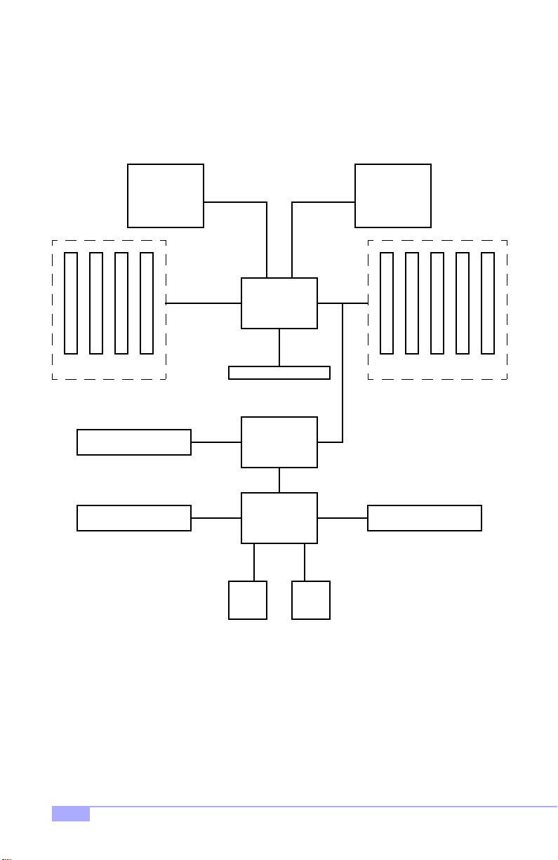
1.2 Tiger MP Syst em Block Diagram
AMD Athlon MP
Processor 0
Socket 462
184-pin Registered
DDR DIMMs
Winbond 83782D H/W
Floppy Device Hardware Monitoring
S2K 200/
266MHz bus
Dual-channel
200/266MHz
DDR SDRAM
bus
SMBus
AMD-762
Controller
AGP slot
AMD-766
Peripheral
Controller
LPC bus
Winbond
W83627HF
System
Bus
S2K 200/
266MHz bus
AGP 4x
bus
AMD Athlon MP
Processor 1
Socket 462
64-bit /
33MHz
PCI bus
64-bit / 33MHz
PCI bus
PCI slots
#1 - 5
Serial
Ports
6
LPT
http://www.tyan.com
Page 7

1.3 Hardware Specifications
Processor Information
Expansion Slots
Chipset Information
Hardware Monitoring
(manufacturing option)
Memory*
Integrated I/O
Integrated PCI IDE
Dual PGA462 ZIF sockets
Supports dual AMD Athlon MP processors
Two onboard VRMs
200MHz and 266MHz system bus support
One AGP slot supports 2x/4x modes
Four 64/32-bit 33MHz 5V PCI v2.2 slots
Two 32-bit 33MHz 5V PCI v2.2 slots
Total of seven usable slots
AMD-760 MP chipset
AMD-762 System Controller
AMD-766 Peripheral Bus Controller
Winbond W83627HF Super I/O ASIC
Winbond W83782D hardware monitoring
3-pin fan monitoring headers
2-pin chassis intrusion header***
CPU temperature and voltage monitoring***
Four 2.5V 184-pin DDR DIMM sockets
Supports up to 3.0GB* PC1600/2100 registered DDR
Supports ECC (72-bit) memory modules
One floppy connector supports up to two drives
Two 9-pin 16550-based serial ports
One 25-pin SPP/ECP/EPP parallel port
Four USB ports (two front panel via optional cable**,
USB v1.1)
PS/2 keyboard and mouse ports
Dual-channel master mode
Up to four Enhanced IDE devices
Support for UltraDMA-100/66/33 IDE and ATAPI compliant devices
BIOS
* Please check Tyan website for memory compatibility information: http://www.tyan.com
** Only certain chassis allow for frontside USB connection. Please check with your chassis vendor for
details on frontside USB connections. Tyan does not provide frontside USB cables.
*** Indicates an optional feature, may not be available on most Tiger MP models
Tiger MP S2460
Phoenix BIOS 4 Mb Flash
Supports APM 1.2 & ACPI 1.0
Auto-configuration of IDE hard disk types
User settings of hardware monitoring***
Multiple boot options
DMI 2.0 compliant
7
Page 8

Form Factor
ATX 12” x 10.3” (304.80mm x 261.62mm)
One 20-pin power connector (requires 30A on +5V line)
Stacked mouse & keyboard ports
Stacked two USB ports
Stacked one parallel, two serial ports
Regulatory
1.4 Software Specifications
OS
FCC Class B (Declaration of Conformity)
European Community CE (Declaration of Conformity)
Windows NT/2000
8
http://www.tyan.com
Page 9

Chapter 2: Board Installation
2.1 Installation
Once you’ve checked th at everything is ins ide the box (see p. 4 for details), you will then be ready to
install your mothe rboard . The m ounti ng ho le patt ern o f the m other board match es t he ATX board specif ications, so your chassis must be capable of suppor ting an Extended ATX board (check the mo therbo ard
dimensions provided on p. 8).
2.2 How to install our products right.. the first time.
Question: what’s the first thing I should do?
The first thing you should do is read the user’s manual. It contains important information which will make
configuration and setup much easier, as well as provide information on device installation and component
setup. By reading through the manual completely before installing your motherboard, you will have a
complete overview on the installation.
2.3 Here are some safety tips:
(1) Ground yourself properly before removing your motherboard from the antistatic bag. Unplug
the power from your computer power supply and touch any metal part on the computer case. (You
might also want to wear a grounded wrist strap.)
(2) Hold the motherboard by its edges and do not touch the bottom of the board.
(3) Avoid touching motherboard components, IC chips, connectors, and leads.
(4) Avoid touching pins of memory modules and chips.
(5) Place motherboard on a grounded antistatic surface or on the antistatic bag.
Having reviewed the precautions above, the next step is to take the motherboard out of the cardboard box
and static bag, hold it by its edges, and place it on a grounded antistatic surface (such as the bag it came
in), component side up. Then, inspect the board for damage.
NOTE: DO NOT APPLY POWER T O THE BOARD IF IT HAS BEEN DAMAGED!
Press down on any of the socketed ICs if it appears that they are not properly seated (the board should
still be on an antistatic mat or on top of the bag it came in). Do not touch the bottom of the board. Remember, don’t take any electronic device out of its protective bag until you are ready to actually start installing
it into the computer case (e.g. setting jumpers, etc.) If you do not ground yourself, you risk “zapping” the
motherboard or adapter card. Subsequent problems may not arise immediately because electrostatic discharge, unlike physical damage, causes the device to fail over time.
Tiger MP S2460
9
Page 10
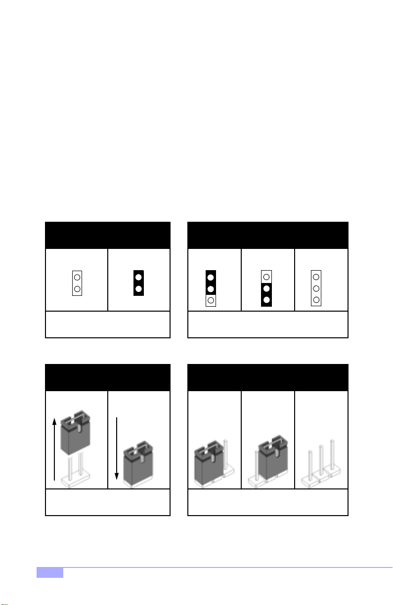
2.4 Quick References for Jumpers
In this manual, the term “close d” and “on” are used wh en referring to jumpers (or jumper pins) that are
active; “open” and “off” a re u s ed whe n re fer ring to j u mp ers (or j um per pin s) that are inactive. See Figure
2.0a and Figure 2.0c for examples of “on” and “off” pins and jumpers.
Jumpers and pins are connec ted by slipping the plastic jum per connector over the top of tw o adjacent
jumper pins (indica ted b y 1-2 or 2-3 ). Th e met al r od insid e the plast ic shell bridg es the gap b etween the
two pins, completing the circ uit. See Figure 2.0b and Figure 2.0d for more examples of 3-pin jumper
connections. NOTE: The small number “1” indicates pin 1.
The tables and maps on the following pages will help you set the jumpers for CPU speed, infrared, and
external connector pin assignments, among others. The miniature motherboard maps will help you locate
the jumpers on your board. Full page maps of the motherboard can be found on the next two pages.
2-pin jumpers
off on
Figure 2.0a
(overhead view)
1-2 2-3 open
3-pin jumpers
1
2
3
Figure 2. 0b
(overhead view)
2-pin jumpers 3-pin jumpers
1-2 2-3 openoff on
11
Figure 2. 0c
(front angle view)
Figure 2. 0d
(front angle view)
1
2
3
1
2
3
10
http://www.tyan.com
Page 11
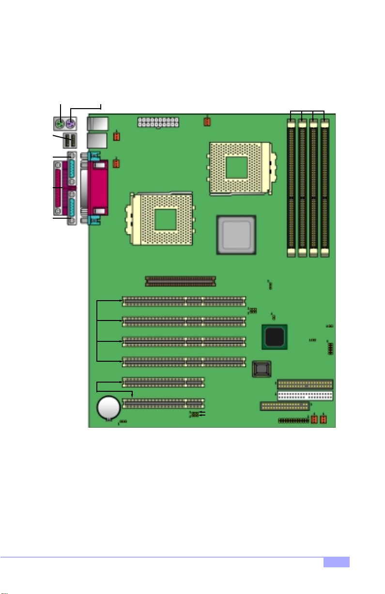
2.5 Map of Motherboard Jumpers
Mouse port
(upper port)
USB
Ports
Serial
port 1
port
Parallel
Serial
port 2
Keyboard port
(lower port)
1
2
3
(4) 64/32-bit
33MHz PCI slots
4
FAN3
P1FAN
20-pin power
connector
CPU1
AGP Slot
P0FAN
AMD-760
CPU0
MP
J52
J53
BIOS
(4) DDR DIMM
J89
J15
sockets
2341
J34
J90
J36
5
6
PCI slots
Battery
(2) 32-bit 33MHz
* Indicates an optional feature, may not be available on most Tiger MP models
J21
J48
J49
Primary IDE
Secondary IDE
FDD
Tiger MP S2460
J12
FAN1
FAN2
11
Page 12
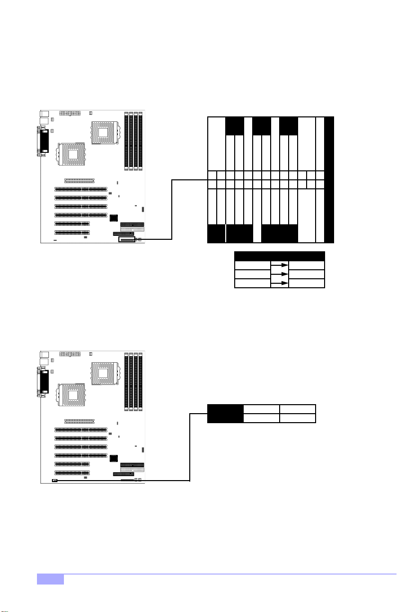
2.6 Setting up Jumpers and Onboard Connectors
Pinouts for certain connectors are available on the Tyan website: http://www.tyan.com
2.6-A. Front Pane l Conn ector (J12)
RST
PWR
26
GND
KEY
LK
SLP
SW
SWITCH
GND
19202122232425
no connect
KEYLOCK
GND
VCC
PWR
LED
SW
SWITCH
GND
1618
SPEAKER
SPEAKER
SW
SWITCH
GND
7
11131517
9
810
1214
no connect
no connect
+5VCC
53
46
VCC GND
HDD LED
1
2
Your chassis will usually come with connectors to install onto
the motherboard, such as HDD and Power LEDs. The Front
Panel Connector has been implemented for such purposes.
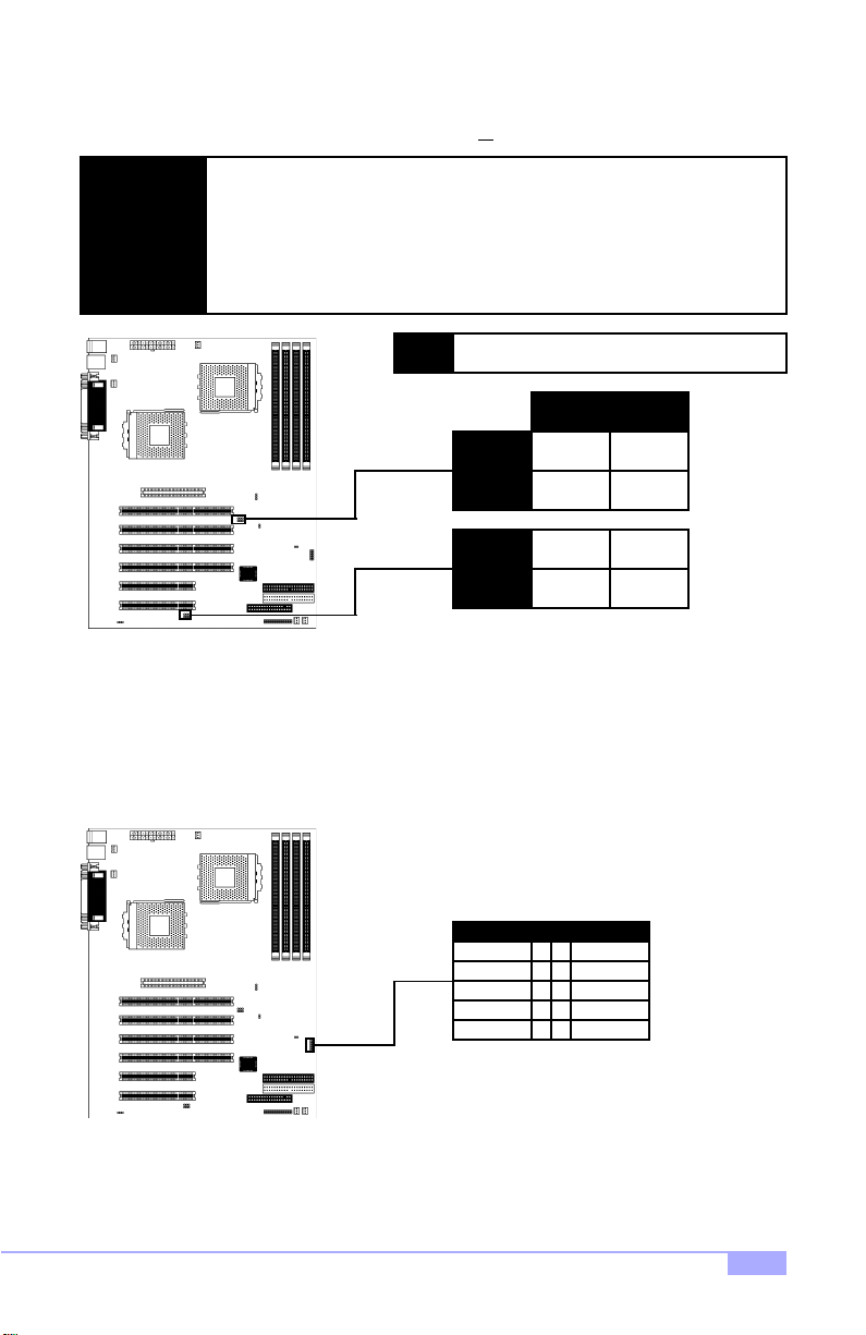
2.6-B. CMOS Reset (J21)
J21
If you have been lo cked out of your system because you forgot your password or set the CMOS incorrectly, or have just finished flashing your BIOS follow the instructions below.
1. Power off the system, and disconnect the power supply
2. Close pins 2-3 on J21
3. Wait about three seconds
4. Close pins 1-2 on J21, then power on the system again
By following this procedure, you will erase your password and reset the CMOS.
Abbreviations
PWR Power
SLP Sleep
1-2
normal
* default is 1-2
ResetRST
2-3
clear
12
http://www.tyan.com
Page 13
2.6-C. CPU Front Side Bus Jumpers (J48, J49; J52, J53) (READ NOTE BELOW)
With these jumpers, the CPU FSB can be set to either 200 or
YOU MUST SET THESE JUMPERS FOR PROPER CPU OPERATION. If your
CPU can only run at 200MHz, altering these FSB jumpers will not make the
CPU run at 266MHz.
NOTE:
Tyan takes no reponsibility and will not be held liable for damage related to operation of the CPU u sing different settings from t hose of the CPU manufa cturer’s
specified default settings.
NOTE:
266MHz.
You MUST set ALL FOUR JUMPERS to the
same speed. Damage may result otherwise!
266MHz 200MHz
J52
J53
J48
J49
2.6-D. Front-side USB H ead er* (J36)
This header allows for a USB connection* . The USB channel on this header is on a separate channel
from the rear USB connections channel. USB v1.1 is supported on this board.
USB Header (J36)
2-3
2-3
1-2
1-2
34
56
78
910
1-2
2-3
2-3
2-3
ground+VCC 1 2
groundsignal out
signal insignal in
signal outground
+VCCground
* Only certain chassis allow for frontside USB connection. Please check with your chassis vendor for
details on frontside USB connections. Tyan does not provide frontside USB cables.
Tiger MP S2460
13
Page 14
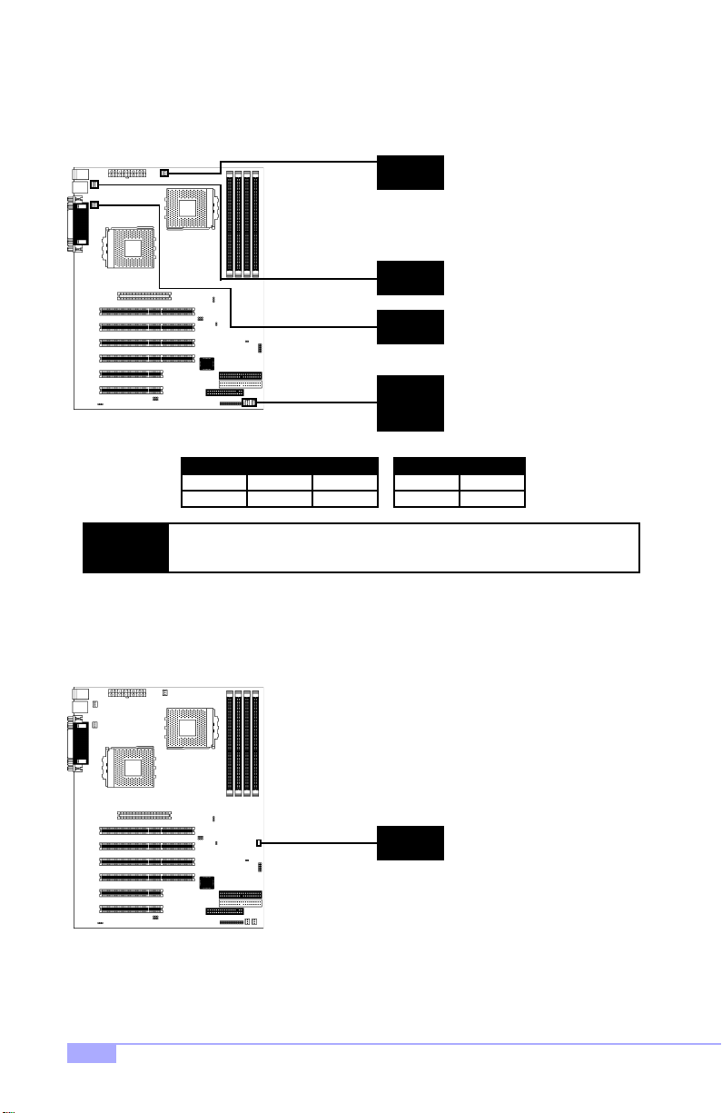
2.6-E. FAN Headers (P0FAN, P1FAN, FAN1, FAN2, FAN3)
These headers allow for extra fans to be installed. P0FAN and P1FAN are reserved for CPU0 and CPU1
(respectively). All other fans are left to the user’s discretion.
P0FAN
FAN3
P1FAN
FAN1
FAN2
12
ground
NOTE:
2.6-F. Chassis Intrusion* Header (J90) ( R ESERVED)
This header is provided in the event that your chassis has a chassis intrusion feature*, and that an application is available to manage this feature.
The FAN connector has a 12V, 300mA limitation. Tyan takes no responsibility
and will not be held liable for damage related to the misuse of any FAN header.
FAN
3
+12V speed
Specifications
12VVoltage
Amperage 300mA
J90
* Indicates an optional feature, may not be available on some Tiger MP models
14
http://www.tyan.com
Page 15
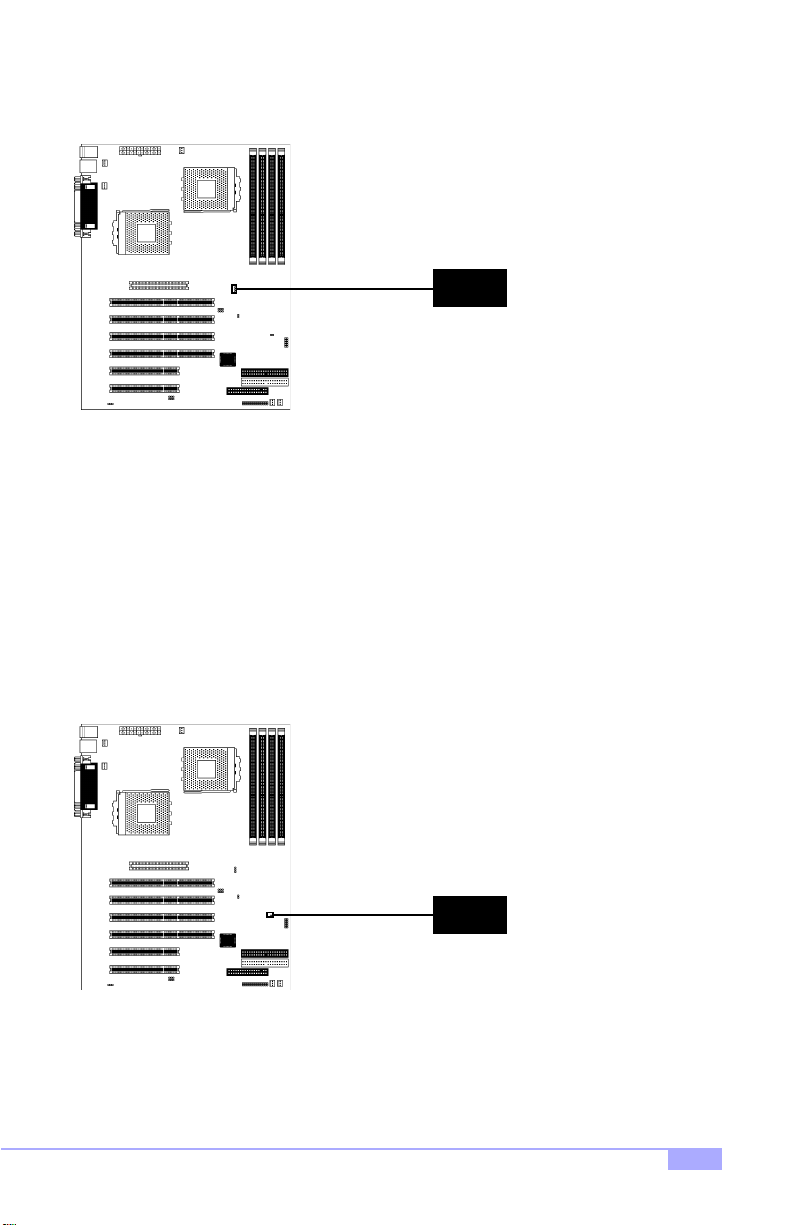
2.6-G. SMBus Connector* (J89)
This is a reserved feature for specific functions not usually required for normal board operation.
J59
2.6-H. Reserved Jumper* (J34) (RESERVED)
This is a reserved feature* for debugging purposes only. DO NOT ADJUST OR TAMPER WITH THIS!
J34
* Indicates an optional feature, may not be available on most Tiger MP models
Tiger MP S2460
15
Page 16
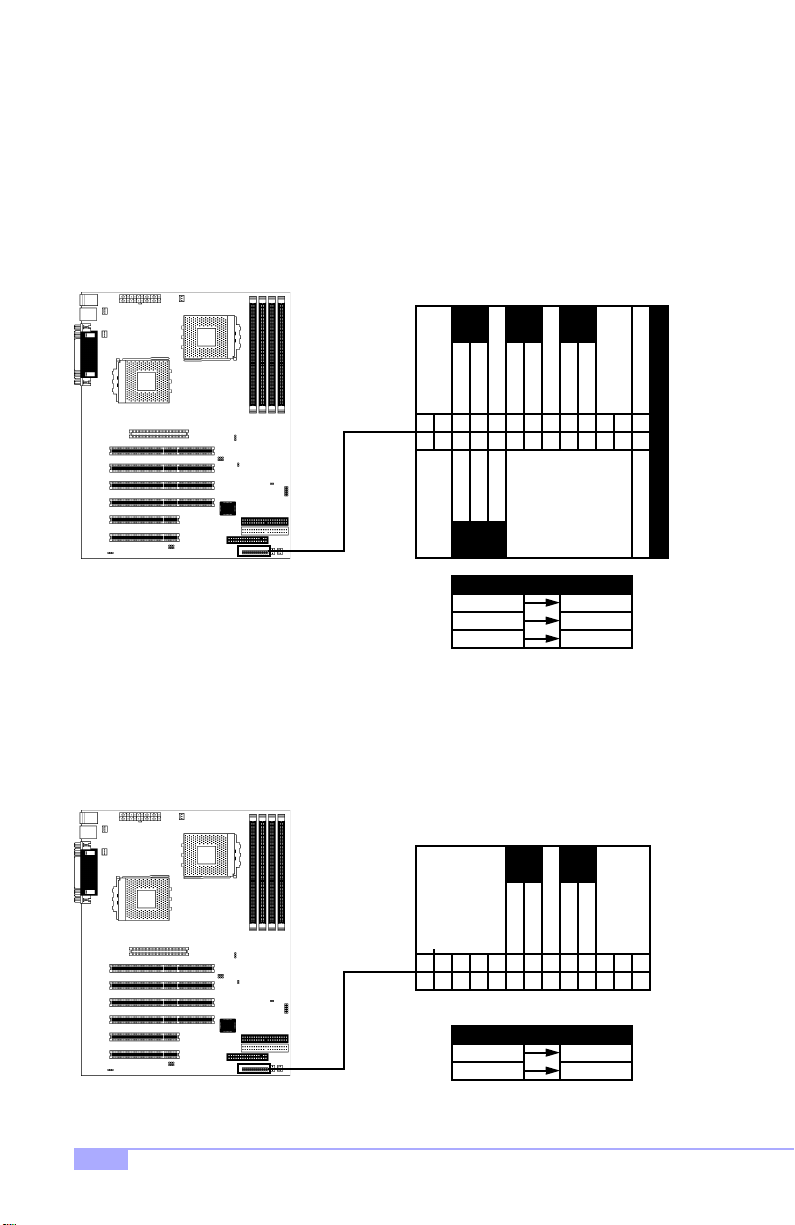
2.6-I. Soft Power Connector
The soft power c onnector is pa rt of jump er block J12 (pins 13 and 15) . This board uses the chipset for
power management, including turning on and off the system. If the power butto n function option in the
BIOS Power Management m enu is set to “On/Off” (wh ich is the d efault), pressing th e power bu tton once
after the BIOS has booted up will turn the system on and off. If the power button function is set to Suspend, pressing the power button once will wake up the system or send it to Suspend mode. In this case,
you cannot turn the syste m o ff unless you shu t d own thr oug h t he Windo ws op er ating syst em or you ho ld
the power button down for four seconds (BIOS-dependent feature).
RST
PWR
SLP
SW
SWITCH
GND
PWR
LED
GND
no connect
VCC
16181920212223242526
SW
SWITCH
SW
SWITCH
GND
9
11131517
GND
7
8101214
53
46
VCC GND
HDD LED
1
2
Abbreviations
PWR Power
SLP Sleep
2.6-J. Hardware Reset Switch Connector Installation
The reset switch on your chassis case provides you with the Hardware Reset function, which is the same
as power on/off, except that the system will immediately execute a cold start afte r the reset button is
pushed. The reset switch needs to be connected to jumper block J12 (pins 7 and 9).
PWR
SW
SWITCH
16181920212223242526
Abbreviations
PWR Power
RST Reset
16
ResetRST
RST
SW
SWITCH
GND
GND
9
7
8101214
53
46
1
2
11131517
http://www.tyan.com
Page 17

2.6-K. Flash Utility
You can upgrade the BIOS of this motherboard by using the Flash Utility (see p. 44). Check the Tyan
website for more details: http://www.tyan.com
BIOS
Tiger MP S2460
17
Page 18

2.7 Mounting the Motherboard into the Chassis
Your chassis may include mounting hardware. If mounting hardware w as included, yo u can use the fo llowing examples to help you in installing your motherboard into the chassis.
If your chassis has the studs integrated into the chassis wall, then yo u would only need to use screws
(possibly included with your chassis) to install the mother board. See the examples ( Figure 2.0, shown
below) for more details.
If the chassis includes mounting hardware without the studs pre-installed, then you will need to install the
motherboard using the mounting hardware as shown in t he examples below. Remember not to overtighten any of the sc rews, or you might risk breaking i nternal tr aces in the su rroundi ng area, or damage
the motherboard in some other way.
Other examples of how to install your motherboard using other hardware (that may or may not have been
included with your chassis) are shown below.
One solution for installing motherboardType of hardware Another solution Another solution
screw
motherboard
base
stud
chassis wall
18
NOTE:
motherboard
base
standoff
chassis wall
motherboard
base
standoff
chassis wall
Figure 2.0
The diagrams above are only representative of a few solu tions for installing a
motherboard into the chassis. The installation procedure fo r installing your motherboard into the chassis may differ.
http://www.tyan.com
Page 19

2.8 Installing Memory
Please keep in m ind t hat although some mem or y m od ul es m ay ap pe ar to b e hi gh -q uali ty, they may contain inferior or subs tandard parts . The type of m emory you choo se to install sho uld be checked ag ainst
the memory compatibility list, which is available from Tyan’s website at http://www.tyan.com
Here are some details of memory installation for this board:
At least one REGISTERED DDR DIMM* must be installed for the system to POST.
Supports 128MB, 256MB, 512MB**, & 1024MB** PC1600/2100 REGISTERED DDR ONLY*.
All installed memory will be automatically detected, so there is no need to set any jumpers.
The motherboard supports up to 3.0GB** of PC1600/2100 REGISTERED DDR memory ONLY*.
Memory Installation Procedure***
Step
Step
* This board supports DDR memory ONLY. Please check that you are using the correct type of memory.
** Not validated at time of print, please check Tyan website for memory compatibility information:
http://www.tyan.com
*** Manufacturer suggestion: start installation with DIMM (bank) 1 (see p.21)
Line your module up so that the pins fit into the socket. There is only one way your DIMM can
1
fit properly. Make sure that the short row of pins is lined up with the short gap in the DIMM
socket, just as the long row of pins should line up with the long gap in the DIMM socket.
short row of pins long row of pins
Insert the DIMM by pushin g the module into th e socket with even force. Do not insert one
2
end and then the other: install the whole module at once or you might bend the DIMM pins.
Make sure the DIMM is securely seated.
Tiger MP S2460
19
Page 20

Step
Lock the DIMM into place by pu shing the clips back on either end of th e socket onto the
3
notches in the ends of the DIMM (see pictures below for details).
1
Removing a DIMM
Removing a DIMM is ju st the r everse: pull ba ck the cli ps from the D IMM (s ee pictu res be low), an d carefully pull the module st raight out. Place the D IMMs in a n anti-static bag as soon as you r emove them to
avoid static damage.
1
2
2
20
http://www.tyan.com
Page 21

Suggested Memo r y Co nf i g ur at ion s
The table below shows some of the po ssible memory configuratio ns. Not all possible c onfigurations
are listed. Your memory configuration may differ from one or more of the combinations** shown below.
CPU 0
DIMM 1**DIMM 2DIMM 3DIMM 4
TOTAL
DIMM 1
DIMM 2
CPU 1
Total possible memory is 3.0GB* PC1600/2100 registered DDR SDRAM
0
0
128MB
128MB
256MB 512MB
256MB
0
0
256MB
0
0
256MB
256MB
256MB
256MB
1024MB
512MB
512MB
0
1024MB
2048MB*
128MB
0
0
0
128MB
128MB
64MB
DIMM 3
1024MB
1024MB
512MB
512MB
3072MB*
DIMM 4
1024MB
1024MB
1024MB
512MB
3584MB*192MB
* Not validated at time of print, please check Tyan website for memory compatibility information:
http://www.tyan.com
** Manufacturer suggestion: start installation with DIMM (bank) 1 (see above)
Tiger MP S2460
21
Page 22

2.9 Installing the CPU and Cooling Fan
AMD Athlon MP processors up to 1.4GHz can be used on this board. For more information on CPU compatibility, check Tyan’s website at: http://www.tyan.com.
When installing your CPU, remember the following:
The CPU is a sensitive electronic component and can easily be damaged by static electricity
Do not touch the CPU pins with your fingers
You should be able to insert the CPU into the socket with virtually no force
Do not press down hard on the CPU as you might bend or break pins, or otherwise damage the
CPU
The CPU voltage will automatically be detected by the motherboard, so there is no need to set
any jumpers or BIOS setting.
Installing the CPU
Before installing the CPU, check it for any visible damage. Make sure none of the pins ar e bent or missing. Be sure where Pin 1 is on both the CPU and the socket. The following steps each have a corresponding picture next to it to help guide you through the installation.
Step
Step
Step
Step
22
Carefully lift the arm of the ZIF socket until it is at a 90 degree angle
1
pointing away from the motherboard. Be very careful not to damage
any components that might be next to the socket.
There are two beveled corners on the CPU, which will match the
2
two angled corners on the socket. Carefully install the CPU by lining
both Pin 1 on the CPU an d Pin 1 on the socket, ma king sure the
pins actually fit into the socket. Do not force the CPU into the
socket: check the pin alignment of CPU pins to socket holes.
Push down lightly on the CPU while lowering the arm on the socket
3
to secure the CPU (se e right). A squeaking noise may be he ard
while lowering the arm, or the socket may make a ‘click’ noise when
the arm is locked into position: these noises are normal.
Install the CPU cooling fans (see next page), the n check
4
Section 2.6-C, p.13 for details on setting the CPU FSB
jumpers.
1
Pin 1
2
Arm moves down
3
to lock CPU
http://www.tyan.com
Page 23

Installing the Cooling Fan(s)
After a CPU has been installed, you will need to install the p roper cool ing device * for the CPU. Th is
device, a heatsink/fan com bination , can be purc hased at ma ny compute r retail store s. Installat ion of the
cooling device* may vary d epend ing on the fan m anufa cturer’s design. You should also take space i nto
consideration when install a cooling device*: make sure the cooling device is not too big, or else you may
end up damaging components around the CPU socket.
Tyan highly recommends that you use a thin layer of
some type of thermal compound (available from many
computer retail stores), between the CPU and heat sink,
to maximize distribution of heat away from the CPU.
Please use extra caution when installing any type of
clamp-style fan, or else dama ge may occur to the CPU
socket, and/or the CPU itse lf. See the picture to the
right for an exa mple of ho w to con nect the co oli ng fan ’s
power supply. Another diagram has also be en pro vided
below, to aid in CPU fan installation onto the socket.
Check the note below* for more details about installation.
Can be used to install
a cooling device
Mounting points on the CPU socket Close-up of fan connector
12
ground
NOTE:
Installing Chassis Fans
Alternatively, if you wish to also install chassis fans for increased cooling, headers are provided to power
those fans as we l l (s e e p. 1 4 , section 2.6-E). Chassis fan installation will vary depending on your chassis
manufacturer’s design. Please check with your chassis manufacturer for details on proper chassis fan
installation.
* Please check the AMD website for recommended cooling device solutions, and more information on
how to install cooling devices: http://www.amd.com/products/cpg/athlon/pdf/23986.pdf
The FAN connector has a 12V, 300mA limitation. Tyan takes no responsibility
and will not be held liable for damage related to the misuse of any FAN jumper.
FAN
3
+12V speed
Tiger MP S2460
Specifications
12VVoltage
Amperage 300mA
23
Page 24

2.10 Connecting IDE and Floppy Drives
A variety of IDE a nd ATAPI-compliant devic es can be installed on this mother board, such as h ard disk
drives (HDDs) and CD-ROMs.
Please keep in mind that on this mothe rboard, the primary IDE connec tor is BLACK, and the secondary IDE
connector is WHITE. See the picture to the rightfor an
example of the IDE cable properly connected to the
motherboard, with the BLUE end of the IDE cable
installed on the motherboard .
Pin 1 on the IDE cable is usually denoted by a red or colored stripe down o ne side of the cable. That side o f the
cable must match Pin 1 on the motherboard’s IDE connector. There will also be a key pin on the cable that
matches with a notch in the ID E connector, to ensure
proper installation. Consult the documentation that came
with your IDE/ATAPI device, or contact the device’s
manufacturer for more details on installation.
Please note that UltraDMA-100/66 IDE HDDs require a
special 80-wire cable (see pictu re at right), which has
additional grounding wires. This cable has been
included with this motherboard for your convenience.
The UltraDMA-100/66 cab le is backwards compatib le
with UltraDMA-33 and legacy IDE HDDs.
BLUE end goes to IDE connector
Pin 1
Only Tyan-approved cables are recommended for this mothe rbo ard. If you are using
NOTE:
Hard Disk Drive Fail message at bootup
No video or beeps during bootup
HDD lights are constantly on
an existing configuration with older cables, your system might not function pro perly.
Use only Tyan-approved cables (i.e. the ones included with your new motherboard).
Some symptoms of incorrectly installed HDDs are...
HDDs are not auto-detected
HDD does not power on
24
May be a Master/Slave configuration problem, bad
IDE cable, or BIOS mis-configuration. Consult the
HDD documentation or contact your HDD vendor.
May be a bad cable or lack of power going to the
drive. Check the cables for damage and bad connections.
Usually means the cable was installed backwards.
Bad IDE cable or defective drives/motherboard. Try
another HDD, or contact your HDD vendor.
Check power cables and cabling. May be a bad
power supply or IDE drive problem.
http://www.tyan.com
Page 25

Connecting Floppy Drives
See the pictu re be low for an example of a fl oppy cab le. Most of the current floppy drives on the ma rket
require that the cable be instal led with th e colored str ipe positi oned ne xt to the power connector. In most
cases, there will be a key pin on the cable which will force a proper connection of the cable.
The first floppy drive (someti mes denot ed as A:) is usually attached to the end of the cable with the twist in it.
Drive B: is usually conn ected to the second or third connector in the cable (the se cond or third connector a fter
you install Drive A:). Refer to your floppy drive’s installation instructions (if available), or contact your dealer if
you are unsure about how to attach the floppy drive(s).
Remember, you can only have 2 floppy drives connected at any given time.
Pin 1
3.5” connector
This connec tor goes
to motherboard
Drive B:Drive A:
5.25” connector Colored stripe
Figure 2.4*
Some symptoms of incorrectly installed FDDs are...
FDDs are not auto-detected
Floppy Drive Fail mes sag e at bo otup
FDD does not pow er on
FDD light is constantly on
Colored stripe
indicates Pin 1
indicates Pin 1
Usually caused by faulty cables, cables put in backwards, or a bad floppy or motherboard. Try another
floppy drive to verify the problem or try another
cable. Also check to see if the onboard floppy is
enabled in the BIOS.
The cable, floppy, or motherboard may be faulty. Try
another cable or floppy drive to verify.
Check power cables and cabling. May be a bad
power supply or IDE drive problem.
Usually signifies that the cable is on backwards.
Reverse the cable at the floppy drive end and try
again.
Match striped side with Pin 1
* Cable may vary. Diagram provided for reference only.
Tiger MP S2460
25
Page 26

2.11 Installing Add-on Cards
There are a few rules you need to follow when installing add-on cards. In order to assure proper operation
and a quick installation, adhere to the following guidelines:
If you are going to install a PCI-bus interface card on your system, be aware that any one of the
six PCI slots can support a Master or Slave device.
NEVER force a card into a slot. If it won’t fit properly, look at the socket on the motherboard to
make sure there are no wires or other obstructions to the slot. Damage will occur otherwise.
NEVER plug an ISA card into a PCI slot. You will void your warranty, and you will damage your
system board if you try to do this.
When plugging the card in, especially when installing long cards, try to push the entire card in at
one time. Don’t force one end of the card into the socket first and then the other, or a rocking
motion between the card and the slot might occur, and could damage the pins within the socket.
Make sure the cards are seated securely into their slots.
Before turning on the system, make sure no cards are touching.
Check the PCI device specifications with the PCI slot specifications (p.5) BEFORE installing!
When installing the add-on cards, make sure the cards are installed with even force; do not insert one
end and then the other. See the before (Figure 2.1a) and aft er (Figure 2.1b) example in sta l la t i on i ma g es
below for details.
1
Check orientation of card when installing
Figure 2.1a*
2
Push card down with even force
Figure 2.1b*
* diagrams are provided as an example for installation, and may not represent an actual slot
26
http://www.tyan.com
Page 27
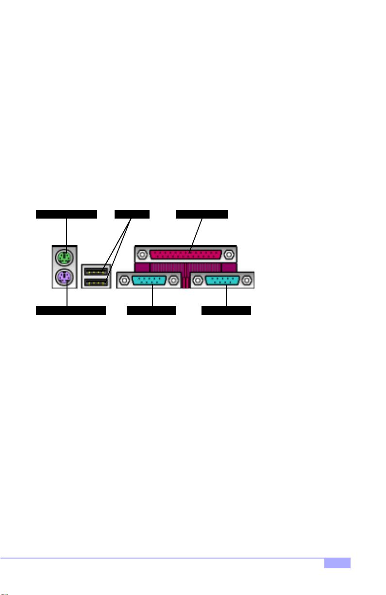
2.12 Connecting PS/2, USB, and Serial Devices
This motherboard includes ports for PS/2 mouse and keyboard, Universal Serial Bus (USB) devices, and
serial and parallel de vices. Please note that the upper PS/2 port is the mouse port, and the lower PS/2
port is for the keyboard (see Figure 2.3 below).
Installation of peripheral/external devices may vary. For details on installation of devices into the various
ports shown below, please consult your device’s documentation, device manufacturer, or your dealer for
details.
Connecting Serial and Parallel Ports
The serial and parallel ports can be used to connect various devices such as a mouse or printer. The connectors can only be connected one way: be sure and check the orientation of the connector before installing it into the port.
PS/2 Mouse Port
PS/2 Keyboard Port
USB Ports Parallel Port
Serial Port 1 Serial Port 2
Figure 2.3
Tiger MP S2460
27
Page 28
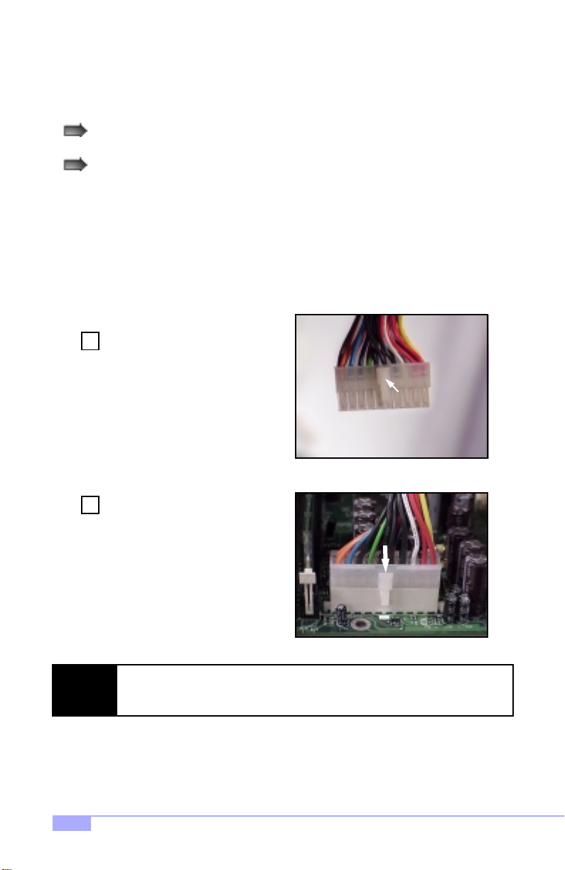
2.13 Connecting the power supply*
This motherboard requires the following:
ATX power supply, one that conforms to ATX standard 2.01 or better
A minimum of 30+A on the +5V power line*
The clip on the power connector should lock over the tab on the onboard connector. Y ou shouldn’t be able
to plug the power connector in any other way but just to be safe, make sure it looks like Figure 2.4b.
Make certain that you do not miss connecting any of the pins because if you do, you will void your warranty and possibly cause damage to yourself and/or your motherboard when the power is turned on. After
connecting the power, make sure the connector is seated firmly into its socket so it will not become loose
or fall off when the computer is jostled or moved.
Shown on the right, in Figure 2.4a, is
Step
the 20-pin connector of the ATX
1
power supply.
Note the clip in the image: it will help
you instal l the plug correctly.
This is the CLIP
Figure 2.4a
Step
**NOTE:
* Check http://www.tyan.com for updates and information about the Tiger MP
28
Shown on the right, in Figure 2.4b, is
2
the 20-pin connector plugged into the
board*.
The clip is over the TAB of the
onboard connector.
When you connect the cable into the
motherboard’s 20-pin onboard connector, it will make a CLICK noise as
it is installed.
This is normal.
Figure 2.4b is no t an image of the Tiger MP ATX power conne ctor. The Tiger MP
power connector tab face s to the inside of the motherboard. Image provided as an
example for installation only.
Note the TAB
Figure 2.4b**
http://www.tyan.com
Page 29

2.14 You are done!
After double-checking the jumper settings and cable connections, and putting the case back together, you
are done setting up the computer.
Installing a new motherboard may seem difficult, but by following these directions, you should have a
fairly uneventful time installing our products. If you do encounter problems, your vendor/dealer will be
able to help you, or you can consult one of our many technical support resources (see p. 63).
Tiger MP S2460
29
Page 30

2.15 Frequently Asked Questions (FAQ)
Q: My system sometimes becomes unstable. How should I check the system?
A: The first thing to do is to check and see if you have any device conflicts related to the IRQ, or DMA. If
you are using Microsoft Windows, the Control Panel is a good place to start investigating the conflict.
Please consult your operating system documentation for details. Secondly, check to make sure you are
using an ATX 2.01 or better power supply that has a minimum of 30A on the +5V power line. Lastl y,
make sure the motherboard is receiving adequete cooling.
Q: I have a question about memory compatibility; what memory will work on my motherboard?
A: Memory compatibility information can be found on Tyan’s website at: http://www.tyan.com
Q: I have a question about CPU compatibility; what CPU will work on my motherboard?
A: CPU compatibility information can be found on Tyan’s website at: http://www.tyan.com
Q: Where can I get additional accessories for my Tyan motherboard?*
A: You can purchase additional accessories such as USB cables*, as well as other Tyan-approved accessories at the Tyan Computer Online Store: http://www.etyan.com
Q: Where do I get pinout information for my motherboard?
A: Pinouts of certain headers are available on the Tyan website: http://www.tyan.com
Q: My motherboard is dead, how do I return it?
A: Contact the place of purchase or your distr ibutor for assistance to return the motherboard for service.
RMA issues will not be handled via e-mail by Tyan Tech Support. Please refer to the URL link here for
more details: http://www.tyan.com/support/html/faq_rma.html
Q: How do I upgrade my BIOS?
A: Check the section about the Flash Utility (see p. 46) for information on upgrading your BIOS. BIOS
update files, flash utilities, and instructions on how to install them are also available from the Tyan website
at: http://www.tyan.com
Q: Why do I get a “CMOS checksum invalid” er ror message during POST?
A: If you get the above error message or “Invalid configuration, run Setup” message, it is an indication that
the CMOS battery needs to be changed. Contact your dealer for assistance. Once you’ve replaced your
battery or flashed your BIOS, don’t forget to check the Clear CMOS section (see p.12) so that you can
reset your CMOS.
* If your chassis supports frontside USB connectors, it will usually come with the necessary cables.
Check that your chassis is frontside USB capable. Please check with your chassis vendor for details.
Tyan does not provide frontside USB cables.
30
http://www.tyan.com
Page 31

Chapter 3: BIOS Setup
Introduction to the BIOS setup
The BIOS is the basic inpu t/output syst em, requ ired by the computer to perform functions suc h as CPU
and hard drive supp ort . T his ch apt er des cri be s differe nt settings for the BIOS that can be use d to co nfigure your system.
The BIOS section of the manual is subject to change without notice and is provided here for reference purposes o nly. The settings an d conf iguration s of the BIOS are current at the t ime of pr int,
and therefore they may not be exactly the same as that displayed on your screen.
This manual describes the BIOS setup prog ram. The setup pro gram lets y ou modify b asic conf iguration
settings. The settings are the n sto red in a de dicated battery-backed memory, called NVRAM, that re tain s
the information when the power is turned off.
The BIOS in your motherboard is a customized version of an industry-standard BIOS for IBM PC AT-compatible personal comp uters. It supports the AMD At hlon famil y of proce ssors, and other com patible p rocessors. The BIOS provides critical low-leve l supp ort for th e system ce ntr al pro cess ing, m em ory, and I/O
subsystems.
The BIOS has been customized by add ing i m por tan t, but non- stan da rd, featu re s such as vir us and password protection, power management, a nd detailed fine- tuning of the ch ipset controlling the s ystem. The
rest of this manual is intende d to guide you through the process of configuring y our system using this
BIOS setup program.
Starting Setup
The BIOS is immediately a cti vat ed wh en yo u fi rs t tur n on the co mp ute r. The BIOS reads s ystem con figuration information in CM OS RAM and be gins the pro cess of checking out the system and configur ing it
through the Power-On Self Test (POST).
When these preliminaries are finishe d, the B IOS seeks a n operat ing system on one of t he data storage
devices (HDD, floppy drive, etc.) If one is found, the BIOS will launch that operatin g system and hand
control of system operations to it. You can start the setup program by pressing the [F2] key while the system is booting up.
Tiger MP S2460
31
Page 32

Setup Keys
The table below shows how to navigate in the setup program using the keyboard.
Key Function
Tab
Left/Right Arrow Keys
Up/Down Arrow Keys Move between selections
Enter
PgUp/PgDn Keys
Getting Help
Press [F1] to display a small help win dow that describ es the appropr iate keys to use and the possib le
selections for the highlighted item. To exit the Help Window press [ESC] or the [F1] key again.
In Case of Problems
If you discover that you have trouble booting the com puter after making and saving changes with the
BIOS setup program, you can restart the computer by either:
Holding the power button down until the computer shuts off
The best advice is to alte r only sett ings th at you th oroughl y under stand. I n particu lar, do not change settings in the Chipset scr een un less you ab solutely sure that you need to. The Chipset defaul ts were ca refully chosen by Tyan or your system manufacturer for the best performance and reliability. Even a
seemingly small change to the Chipset setup may cause the system to become unstable.
Moves from one selection to the next
Change from one menu to the next
Opens highlighted section
Change setting
Setup V ariations
Not all systems have the same setup program. While th e basic look and functio n of the setup program
remains more or le ss th e sam e f or all sy stem s, t he ap pea ran c e of your Setup screen may differ from the
screens shown here. Each sy stem design and chipset combination requ ire custom configurations. In
addition, the fina l appearance of the setup pr ogram depends on your system designer. Your system
designer can decide tha t certain item s should not be available for use r configurati on, and remove t hem
from the BIOS setup program.
32
http://www.tyan.com
Page 33

3.1 Main Setup
In this screen, you can alter general features such as the date and time, as well as access the IDE configuration screens. Note t hat the options listed below ar e f or opti o ns t hat can dir ectl y b e ch an ged wi thin the
Main Setup screen.
FORMAT:
System Time
System Date
Legacy Diskette A (..B)
Primary Master/Slave Discussed on p. 34
Secondary Master/Slave Discussed on p. 34
System / Extended Memory
Large Disk Access Mode
OPTIONS: hh = hours
NOTES: System time works on 24-hour format
FORMAT:
OPTIONS: mm = month
FORMAT:
OPTIONS: 360KB, 5 1/4”
NOTES: This option is provided for your floppy device
FORMAT:
OPTIONS: N/A
NOTES: Cannot be altered. Provided for your informa-
FORMAT:
OPTIONS:
NOTES: A large disk is one that has more than 1024
hh:mm:ss
mm = minutes
ss = seconds
mm/dd/yyyy
dd = day
yyyy = year
[size in MB] [media dimensions]
1.2MB, 5 1/4”
720KB, 3 1/2”
1.44/1.2 5MB, 3 1/2”
2.88MB, 3 1/2”
Not Installed
Disabled
needs. It is also linked to the Boot Sequence
in the Boot Menu.
[size in KB]
tion only.
[option]
Other Select Other if you have another
operating system such as UNIX.
cylinders, more than 16 heads, or more than
63 tracks per sector.
Boot Summary Screen
Tiger MP S2460
FORMAT:
OPTIONS: Disabled
NOTES: Enables or disables the information screen
[option]
Enabled
seen on boot-up of the system.
33
Page 34

3.1-A. Master and Slave screens
The following options are for setting the configuration of the IDE devices installed in the system.
Type
Cylinders
Heads
FORMAT:
OPTIONS:
NOTES: All options are dependent on the drive.
FORMAT: [#]
OPTIONS:
NOTES: All options are dependent on the drive.
FORMAT: [#]
OPTIONS:
NOTES: All options are dependent on the drive.
[option]
None
1 to 39
User The user must define the
Auto Auto-detect the drive
IDE Removeable Removeable read-and-
CD-ROM Readable CD-ROM drive.
AT API Removeable Removeable ATAPI media
1 to 65,536 Number of cylinders.
1 to 16 Number of read/write
Auto-typing is not able to
supply the drive type, or
the user ha s selected
None to disable any
drives that might be
installed.
Pre-configured drive
parameters. This option is
dependent on your drive.
different parameters of
the drive.
parameters.
write media (e.g. Zip
drive).
(e.g. USB Zip drive).
heads.
34
Sectors/Track
Landing Zone
Write Precomp
FORMAT: [#]
OPTIONS:
NOTES: All options are dependent on the drive.
FORMAT: [#]
OPTIONS:
NOTES: IDE devices do not require a Landing Zone.
FORMAT: [#] or [None]
OPTIONS:
NOTES: IDE devices do not require a Write Precomp.
1 to 63 Number of sectors per
1 to 2048 Number of the cylinders
1 to 2048
None
track.
specified as the landing
zone for the read/write
heads.
Number of the cylinder at
which to change the write
timing.
http://www.tyan.com
Page 35

(master and slave screens, continued)
Multi-Sector Transfers
LBA Mode Control
32-bit I/O
Transfer Mode
FORMAT: [option]
OPTIONS:
NOTES: All options are dependent on the drive.
FORMAT:
OPTIONS:
NOTES:
FORMAT:
OPTIONS:
NOTES:
FORMAT:
OPTIONS:
NOTES:
Disabled DIsables the feature.
Standard Standard is 1 sector per
2 sectors
4 sectors
8 sectors
16 sectors
[option]
Disabled / Enabled Enabling LBA causes logi-
All options are dependent on the drive.
[option]
Disabled / Enabled Enables 32-bit communi-
All options are dependent on the drive.
[option]
Standard
Fast PIO 1
Fast PIO 2
Fast PIO 3
Fast PIO 4
The Setup menu only lists those options supported by the drive and platform.
block.
Number of sectors trans-
ferred per block.
cal block addressing to be
used in place of Cylinders, Heads, and Sectors.
cation between CPU and
IDE card. Requires PCI or
local bus.
Selects the method for
transferring data between
the HDD and system
memory.
SMART Monitoring
Tiger MP S2460
FORMAT:
OPTIONS:
[option]
Disabled / Enabled Sel f- Mon itor ing An alysis-
Reporting Technology,
which monitors condition
of the HDD and reports
when a catastrophic IDE
failure is about to happen.
35
Page 36

3.2 Advanced Setup
Options such as I/O device interfaces can be altered through this scree n.
FORMAT: [option]
OPTIONS:
Reset Configuration Data
NOTES: Select Yes when required to restore the manu-
Yes Erases all configuration
No Does not erase ESCD.
facturer’s defaults.
data in a section of memory for ESCD (Extended
System Configuration
Data) which stores the
configuration set tings for
non-PnP plug-in devices.
FORMAT: [option]
USB Host Controller
USB BIOS Legacy Support
Chipset Configuration Discussed on p. 38
Keyboard Configuration Discussed on p. 39
I/O Device Configuration Discussed on p. 39
Onboard PCI IDE
Serial Port A (..B)
OPTIONS:
FORMAT: [option]
OPTIONS:
FORMAT: [option]
OPTIONS:
FORMAT: [option]
OPTIONS:
Disabled / Enabled Enables or disables the
Disabled Enables or disables sup-
Both ‘Both’ enables both IDE
Disabled Disables the ports.
Primary Enables the primary port
Secondary Enables the secondary
Disabled ‘Disabled’ turns off the
Enabled ‘Enabled’ requires you to
Auto ‘Auto’ makes the BIOS
USB onboard controller.
port for Legacy USB.
ports.
only.
port only.
port.
enter the base I/O
address and the INT number on the next line.
configure the port during
POST.
36
http://www.tyan.com
Page 37

(advanced setup, continued)
Mode
Base I/O
Interrupt
Parallel Port
Mode
FORMAT: [option]
OPTIONS:
NOTES: This option is only for Serial Port B.
FORMAT: [option]
OPTIONS:
NOTES: Recommended combinations include ‘3F8,
FORMAT: [option]
OPTIONS:
NOTES: Recommended combinations include ‘3F8,
FORMAT: [option]
OPTIONS:
FORMAT: [option]
OPTIONS:
Normal Selects the mode to use.
3F8, 2F8
3E8, 2E8
IRQ4’ and ‘2F8, IRQ3’.
IRQ4
IRQ3
IRQ4’ and ‘2F8, IRQ3’.
Disabled ‘Disabled’ turns off the
Enabled ‘Enabled’ requires you to
Auto ‘Auto’ makes the BIOS
Output only Standard one-way proto-
Bi-directional Two-way protocol for par-
EPP Enhanced Parallel Port
ECP Enhanced Capability Port
These options are dependent on the IRQ, and vice
versa.
These IRQs are paired
with the Base I/O option.
port.
enter the base I/O
address and the INT number.
configure the port during
POST.
col for parallel devices.
allel devices.
interface may provide
higher bandwidth, if an
EPP device is used.
interface may provide
higher bandwidth, if an
ECP device is used.
Base I/O
Interrupt
Tiger MP S2460
FORMAT: [option]
OPTIONS:
FORMAT: [option]
OPTIONS:
378
278
3BC
IRQ5
IRQ7
These options appear
when the parallel port is
set to ‘Enabled’.
These options appear
when the parallel port is
set to ‘Enabled’.
37
Page 38

(advanced setup, continued)
DMA Channel
PCI Configuration Discussed on p. 40
3.2-A. Chipset Configuration screen
Options related to the graphics interf ace can be alte red throu gh thi s scree n.
Graphics Aperture
FORMAT: [option]
OPTIONS:
FORMAT: [option]
OPTIONS:
DMA1
DMA3
32MB
64MB
128MB
256MB
512MB
1GB
None
These options appear
when parallel port is set to
‘Enabled’.
Sets the size of the memory area reserved for storage of graphics data
structures used by the
AGP.
SERR Signal Condition
ECC Config
FORMAT: [option]
OPTIONS:
FORMAT: [option]
OPTIONS:
None
Single bit
Multiple bits
Both ERR signal output for
Disabled No error checking.
EC (single bit) Error checking & status
ECC (multiple bits) Error checking & status
ECC Scrub Error checking & status
ERR signals not output
under any condition.
ERR signal output for a
single bit
ERR signal output for
multiple bits
both instances.
report enabled. Data not
corrected.
report enabled. Data is
corrected.
report enabled. Data is
corrected. Memory contents are corrected
(scrubbed) after all reads
with errors.
38
http://www.tyan.com
Page 39

3.2-B. Keyboard Configuration screen
Options related to the keyboard can be altered throu gh thi s scree n.
FORMAT: [option]
OPTIONS:
NumLock
Auto ‘Auto’ will have the BIOS
On NumLock will be on after
Off NumLock will remain off
taking control of the NumLock key at POST.
POST.
after POST.
FORMAT: [option]
OPTIONS:
Keyboard auto-repeat rate
FORMAT: [option]
OPTIONS:
Keyboard auto-repeat delay
3.2-C. I/O Configuration screen
Options related to the I/O interface can be altered through this screen.
FORMAT: [option]
OPTIONS:
PS/2 Mouse
FORMAT: [option]
OPTIONS:
Floppy disk contro l ler
30/sec
26.7/sec
21.8/sec
18.5/sec
13.3/sec
10/sec
6/sec
2/sec
1/4 sec
1/2 sec
3/4 sec
1 sec
AutoDetect BIOS will auto-detect the
Disabled Disable any installed PS/2
Enabled Enable any installed PS/2
Enabled Onboard floppy controller
Disabled Onboard floppy controller
Auto BIOS will detect the pres-
Sets speed at which keystrokes will be input into
the system.
Sets speed at which keystrokes will initially be
delayed from being input
into the system.
presence of a PS/2
mouse.
mouse device.
mouse device.
is enabled.
is disabled.
ence of a floppy controller.
Tiger MP S2460
39
Page 40

3.2-D. PCI Configuration screen
Options related to the PCI slots can be altered through this screen.
Primary Video
FORMAT: [option]
OPTIONS:
AGP
PCI
Selects primary video
boot device
FORMAT: [option]
OPTIONS:
PCI Device, Slot 1 (..2, 3, 4, 5)
3.2-E. PCI/PnP IRQ Exclusion screen
Options related to the PCI/PnP interrupts can be altered through this screen.
FORMAT: [option]
OPTIONS:
IRQ3 [..4, 5, 7, 10, 11]
3.2-F. PCI /PnP UMB Exclusion screen
Options related to the upper memory buffer (UMB) can be altered through this screen.
FORMAT: [option]
C800 - CBFF
CC00 - CFFF
D000 - D3FF
D400 - D7FF
D800 - DBFF
DC00 - DFFF
OPTIONS:
Option ROM Scan Enables or disables
(Enable or Disable)
Enable Master Enables selected device
(Enable or Disable)
Latency Timer Sets the bus master clock
(0020h, 0040h,
0060h, 0080h,
00C0h, Default)
Available
Reserved
Available
Reserved
device expansion ROM.
as a PCI bus master. Not
every device can function
as a master. Check your
device documentation.
rate. A device that has
high priority and high
throughput may benefit
from a greater value.
Sets the availability of PCI
IRQs to ISA devices. If set
to ‘Reserved’, ISA devices
are excluded from using
the IRQ in question.
Sets the availability of the
UMB address to ISA
devices. If set to
‘Reserved’, ISA devices
are excluded from using
the UMB address in question.
40
http://www.tyan.com
Page 41

3.3 Security Setup
Security options can be altered through this screen.
FORMAT: [press the [ENTER] key]
OPTIONS:
Set Supervisor Password
[Enter] Enter up to seven alpha-
numeric characters. You
will be asked to confirm
the password. In related
systems, features will be
accessible only by users
who use the supervisor
password.
FORMAT: [option]
OPTIONS:
Password on boo t
FORMAT: [option]
OPTIONS:
Fixed disk boot sector
FORMAT: [option]
Diskette Access
3.4 Power Setup
Power management options can be altered through this screen.
ACPI Enabled
OPTIONS:
FORMAT: [option]
OPTIONS:
Disabled
Enabled
Normal Disk is unrestricted.
Write Protect Write protect the boot
Disabled
Enabled
No
Yes
Enabling requires a password on boot. Also
requires prior setting of
the supervisor password.
If the supervisor password
is set and this option is
disabled, the BIOS
assumes the user is booting.
sector on the fixed disk.
Fixed disk will required a
password to Fdisk or format the drive.
Enabling this feature will
password-restrict diskette
drive access.
ACPI can be enabled or
disabled using this option.
Power Savings
Tiger MP S2460
FORMAT: [option]
OPTIONS:
Customized User must define the
Maximum Power
Savings
Maximum Performance
Disabled Turns off power manage-
power saving values.
Each of these options will
pre-define power saving
values for the user.
ment.
41
Page 42

(power setup, continued)
Standby Timeout
Auto Suspend Timeout
Resume on modem ring
Resume on time
Resume Time
FORMAT: [option]
OPTIONS:
FORMAT: [option]
OPTIONS:
FORMAT: [option]
OPTIONS:
FORMAT: [option]
OPTIONS:
FORMAT: [00:00:00]
OPTIONS:
Off
1 Minute
2 Minute
4 Minute
6 Minute
8 Minute
12 Minute
16 Minute
Off
5 Minutes
10 Minutes
15 Minutes
20 Minutes
30 Minutes
40 Minutes
60 Minutes
On
Off
On
Off
hours
minutes
seconds
Inactivity period required
to put system in Standby
(partial power shutdown).
Inactivity period required
after Standby to Suspend
(maximum power shutdown).
Wakes up system when
an incoming call is
detected by the modem.
Wakes up system at preset time.
Preset time to wake system up.
42
Resume Date
FORMAT: [00/00/0000]
OPTIONS:
month
day
year
Preset date to wake system up.
http://www.tyan.com
Page 43

3.5 Boot Setup
Boot settings can be altered through this screen. All options are arranged by vertical priority.
(menu dependent on devices
detected
3.6 Exit Menu
Selecting “Exit” will display this menu.
Exit Saving Changes
Exit Discarding Changes
Load Setup Defaults
Discard Changes
FORMAT: [option]
OPTIONS:
FORMAT: [option]
OPTIONS:
FORMAT: [option]
OPTIONS:
FORMAT: [option]
OPTIONS:
FORMAT: [option]
OPTIONS:
(dependent on
devices detected)
Yes
No
Yes
No
Yes
No
Yes
No
Each item detected as a
removeable device, will
be listed in this section.
As the user presses the
‘+’ key, the item will move
up in priority. The item at
the top will take first priority, the second item takes
next highest priority, and
so on.
Saves changes to CMOS
and exits BIOS setup.
Discard any changes and
then exit BIOS setup.
Loads preset defaults
from CMOS.
Discards all changes.
Save Changes
Tiger MP S2460
FORMAT: [option]
OPTIONS:
Yes
No
Saves all changes.
43
Page 44

Chapter 4: System Resources
Note: If you experience problems with setting up your system, always check the following things in the
following order:
MEMORY, VIDEO, CPU
By checking these items, you will most likely find out what the problem might have been when setting up
your system. For more information on troubleshooting, check the Tyan website at http://www.tyan.com
4.1 Beep Codes
Fatal errors, which halt the boot process, are communicated through a series or audible beeps. For example, if the Phoenix BIOS POST can initialize the video but an error occurs, an error message will be displayed. If it cannot display video, it will convey a series of beeps.
If you hear one long beep followed by two short beeps, then a video problem has probably occured and
the BIOS is having difficulty initializing the video display. Any other beep sequences that may or may not
occur are probably due to memory problems.
4.2 Flash Utility
Every BIOS file is unique for the motherboard it was designed for. For Flash Utilities, BIOS downloads,
and information on how to properly use the Flash Utility with your motherboard, you must check the Tyan
website: http://www.tyan.com
NOTE:
44
Please be aware that by flash ing your BIOS, you a gree that in the eve nt of a BIOS
flash failure, you must contact your dealer fo r a replacement BIOS. T here are no
exceptions. Tyan does not have a policy of replacing B IOS chips directly with end
users. In no event will Tyan be held responsible for damage done to the BIOS by the
end user.
http://www.tyan.com
Page 45

Appendix I: Glossary
ACPI (Advanced Configuration an d Power Interface): a pow er m anage ment s pecific ation th at al lows the
operating system to control the amount of power distributed to the computer’s devices. Devices not in use
can be turned off, reducing unnecessary power expenditure.
AGP (A
ccelerated Graphics Port): a PCI-base d inte rfa ce whic h was de sign ed spe ci fical ly for dem and s of
3D graphics applications. Th e 32-bi t AGP chann el directl y links the grap hics con troller to the main memory. While the channel runs at only 66 MHz, it supports data transmission during both the rising and falling
ends of the clock cycle, yielding an effective speed of 133 MHz.
ATAPI (AT
the disk controller on the dev ice itsel f. It all ows CD -ROMs an d tape dr ives to be co nfigure d as maste r or
slave devices, just like HDDs.
ATX: the form factor designed to rep lace the AT form factor. It improves on the AT design by rotating the
board 90 degrees, so tha t the IDE connecto rs are close r to the drive b ays, and the CPU is closer to the
power supply and cooling fan. The keyboard, mouse, USB, serial, and parallel ports are built-in.
Bandwidth: refers to carrying cap aci ty. The greater the ban dw idt h, th e m ore dat a the bus, phone line, or
other electrical path, can carry. Greater bandwidth, then, also results in greater speed.
BBS (B
of all Initial Program Load (IPL) devices, and then stores that list in NVRAM. IPL devices have the ability
to load and execute an OS, as well as provide the ability to return to the BIOS if the OS load process fails
for some reason. At that point, the next IPL device is called upon to attempt loading of the OS.
BIOS (B
instructions for controlling your computer’s hardware. Both the operating system and application software
use BIOS routines to ensure compatibility.
Buffer: a portion of RAM which is u sed to te mp ora ril y sto re d ata , usu all y fr om an a pplic a tion , tho ugh i t is
also used when printing, and in most keyboard dr ivers. The CPU can manipulat e data in a buffer before
copying it, all at once, to a disk drive. While this improves syst em performance --- readin g to or writing
from a disk drive a single time is much fa ster than doing so repeatedly --- there is also the possi bility of
losing your data should the system cr ash. Inf ormatio n sto re d in a bu ffer is te mp orarily st ore d, n ot p ermanently saved.
Attachment Packet Interface): also known as IDE or ATA; a drive implementation that includes
IOS Boot Specification): is a feature within the BIOS th at creates, p rioritizes , and m aintains a list
asic Input/Output System): the program that resides in the ROM chip, an d provides the basic
Bus: a data pathway. The term is used especially t o refer to the connec tion bet ween the pr ocessor and
system memory, and between the processor and PCI or ISA local buses.
Tiger MP S2460
45
Page 46

Bus mastering: allows peripheral devices and IDEs to access the system memory without going through
the CPU (similar to DMA channels).
Cache: a temporary storage area for data that will be needed often by an application. Using a cache lowers data access times, since th e ne ed ed i n for mat ion is stored in the SRAM instead of in the slow D RA M .
Note that the cache is also mu ch sm al le r th an your re gu lar m em or y: a typi ca l cach e size i s 51 2KB , wh ile
you may have as much as 4GB of regular memory.
Cache size: refers to the physical size of the cache onboard. This should not be confused with the cacheable area, which is the total amoun t of m emory wh ich ca n be sc anned by the syste m in se arch of da ta to
put into the cache. A ty pical setup would b e a ca che si ze o f 512KB , an d a ca cheable area of 5 12MB. In
this case, up to 512KB of the main memory onboard is capable of being cached. However, only 512KB of
this memory will be in the cache at any given moment. Any main memory above 512MB could never be
cached.
Closed and open jumpers: jumpers and jumper pins are active when they are “on” or “closed”, and inactive when they are “off” or “open”.
CMOS (C
the BIOS.
COM port: another name fo r t he seri a l po rt, whi ch is ca l led as su ch beca use i t tr an smits the eig ht b i ts o f
a byte of data along one w ire , an d re cei ve s da ta on another single wire (t ha t is, th e da ta i s t ran smi t ted in
serial form, one bit after another) . Parallel ports tran smit the bits of a byte on eight different w ires at the
same time (that is, in parallel form, eight bits at the same time).
DDR (D
output on both the rising and falling edge of th e system clock rather than on just the rising ed ge, potentially doubling output.
DIMM (D
need to be installed in pairs.
DIMM bank: sometim es called DIMM sockets, because the physical slot and th e logical unit are the
same. That is, one DIMM module fits into one DI MM socket, which is capable o f acting as a memory
bank.
DMA (D
(like soundcards or keyboards) to access the main memory without involving the CPU. This frees up CPU
resources for other tasks. As with IRQs, it is vital that you do not double up devices on a single line. Plugn-Play devices will take care of this for you.
Doze mode: in this mode, only the CPU’s speed is slowed.
omplementary Metal-Oxide Semiconductors): chips that hold the basic startup information for
ouble Data Rate) : is a te chno l ogy desig ned to do ub l e the clock sp eed of th e me mo ry. It activates
ual In-line Memory Modul e): faster and m ore capacious form of R AM than SIMM s, and do not
irect Memory Access): channels that are similar to IRQs. DMA chann els allow hardware devices
46
http://www.tyan.com
Page 47

DRAM (Dynamic RAM): wide ly available, very afford able form of RAM whi ch has the unfortunate tendency to lose data if it is not recharged regularly (every few milliseconds). This refresh requirement
makes DRAM three to ten times slower than non-recharged RAM such as SRAM.
ECC (E
rror Correction Code or Error Checking and Correcting): allows data to be checked for errors
during run-time. Errors can subsequently be corrected at the same time that they’re found.
EEPROM (E
unlike normal ROM, be upd ated. T his allow s you to keep up with ch anges in th e BIOS pro gram s withou t
having to buy a new chip. Tyan’s BIOS updates can be found at http://www.tyan.com
ESCD (E
in the system BIOS. This information helps properly configure the system each time it boots.
Fault-tolerance: a term descri bin g a syst em whe re on e com pon ent ca n qui ckl y be repl ace d wi thout cau sing a loss of service, such as in a RAID system.
Firmware: low-level software that controls the system hardware.
Form factor: an i nd ust ry t erm fo r the size, sh ape , p ow er su ppl y typ e, a nd ext ern al c onn ecto r type of the
Personal Computer Board (PCB) or motherboard. The standard form factors are the AT and ATX,
although Tyan also makes some Baby-AT and ATX Footprint boards.
Global timer: onboard hardware timer, such as the Real-Time Clock (RTC).
Handshaking: a form of encryption. One system, typically the server, sends an encryption scheme to
another agent, typically a client. Thus, the client’s data is protected during transmittal to the server.
HDD: stands for H
H-SYNC: controls the horizontal synchronization/properties of the monitor.
lectrically Erasable Programmable ROM): also called Flash BIOS, is a ROM chip which can,
xtended System Configuration Data): a format fo r stori ng infor ma tion a bou t P lug- n-Pl a y device s
ard Disk Drive, a type of fixed drive.
ntegrate d Circuit): the formal name for the computer chip.
IC (I
ntegrated Device/Drive Electronics): a simple, self-contained HDD interface. It can handle drives up
IDE (I
to 8.4 GB in size. Almost all IDE s sold now are in fact Enhanced IDEs (EIDEs), with maximum capa city
determined by the hardware controller.
IDE INT (IDE Interrupt): a hardware interrupt signal that goes to the IDE.
I/O (I
nput/Output): the connection between your computer and another piece of hardware (mouse, key-
board, etc.)
Tiger MP S2460
47
Page 48

Initial Program Load ( IPL): a feature built into BBS-compliant devices, describing those devices as
capable of loading and execu ting an OS, as w ell as being able to pro vide control ba ck to the B IOS if the
loading attempt fails.
IPL: see Initial Program Load.
IRQ (Interrupt Request): an electronic request that runs from a hardware device to the CPU. The interrupt
controller assigns priorities to incoming requests and delivers them to the CPU. It is important that there is
only one device hooked up t o each IRQ line; d oubling u p devices o n IRQ lin es can lock u p your sys tem.
Plug-n-Play operating systems can take care of these details for you.
ISA (I
ndustry Standard Architecture): a slower 8- or 16-bit bus (data pathway).
Latency: the amount of time that one part of a system spends waiting for another part to catch up. This is
most common when the syste m s end s da ta o ut t o a per iphe ra l device, and it waiting for the perip her al to
send some data back (peripherals tend to be slower than onboard system components).
Mirroring: see RAID.
NVRAM: ROM and EEPROM are both examples of Non-Volatile RAM, memory that holds its data without
power. DRAM, in contrast, is volatile.
OEMs (O
and hardware inside their case and sell them.
Parallel port: transmits the bits of a byte on eight different wires at the same time (that is, in parallel form,
eight bits at the same time).
PCI (P
ISA bus. Local buses are those which operate within a single system (as opposed to a network bus, which
connects multiple systems).
PCI PIO (PCI P
modes use the C PU for dat a transfer ( in contrast, D MA channel s do not). PCI refers to the type of bus
used by these modes to communicate with the CPU.
PCI-to-PCI bridge: allows you to connect multiple PCI devices onto one PCI slot.
Pipeline burst SRAM: a fast secondary cache. It is used as a secondary cache because SRAM is slower
than SDRAM, but usually large r. Data is cached first to the fa ster prim ary cache, and then, when the pr imary cache is full, to the slower secondary cache.
riginal Equipm ent Manufacturers): Compaq or IBM package other companies’ mother boards
eripheral Component Interconnect): a 32 or 64-bit local bus (data pathway) which is faster than the
rogrammable Input/Output) modes: the data transfe r modes used by IDE dri ves. These
48
http://www.tyan.com
Page 49

Pipelining: improves system perform ance by allowing the CPU to begin exe cuting a second instru ction
before the first i s com pleted. A pipeline can be li ke ned to a n asse mb ly li ne , wi t h a g iven pa rt of the pipeline repeatedly executing a set part of an operation on a series of instructions.
PM timers (P
utes until the system times out and enters sleep, suspend, or doze mode.
PnP (P
require little set-up to use. Novice end use rs can simply plu g them into a compu ter that is run ning on a
Plug-n-Play aware operatin g system ( such as Win dows 98), and go to wo rk. Devices a nd oper ating systems that are not Plug-n-Play require you to reconfigu re your system each time you ad d or change any
part of your hardware.
PXE (P
agement 2.0 baseline sp ecification . PXE was de signed to de fine a standa rd set of pr eboot pro tocol services within a client, towards the goal of allowing networked-based booting to boot using industry
standard protocols.
RAID (R
on many hard drives. B y using this m ethod, the data is sto red redundan tly, also the multiple hard drives
willl appear as a single drive to the operating system. RAID level 0 is is known as striping, where data is
striped (or overla pped) across multiple hard drives, but offers no fault-tolerance. RAID level 1 is known as
mirroring, which stores th e data within at least two hard dr ives, but does not stripe. RAID level 1 also
allows for faster access time and fault-toleranc e, since either hard dr ive can be read at the s ame time.
RAID level 0+1 is both str iping and mir roring, providing fault-toler ance, striping, an d faster access all at
the same time.
RAM (R
without touching the adjacent data, is ofte n used to refer to the system’s main memory. This memory is
available to any program running on the computer.
ower Management time rs) : software timers that count down the num ber of se con ds or min-
lug-n-Play): a design standard that has become ascendant in the industry. Plug-n-Play devices
reboot Exe c uti o n Environment): one of four components that together make up the Wired for Man-
edundant Array of Independ ent Disks): a way for the same dat a to be stor ed in different places
andom Access Memory): technically refers to a type of memory where any byte can be accessed
ROM (R
ead-Only Memory): a storage chip wh ich contains the BIOS ; the basic instructions req uired to
boot the computer and start up the operating system.
SDRAM (S
addresses open simultaneo usly. By transferring data alternat ely from one set of ad dresses and th en the
other, SDRAM cuts down on the delays associated with non -synchronous RAM, which mus t close one
address bank before opening the next.
Serial port: called as such because it tran smits the eight bits of a byte of data along one wire, and
receives data on another single wire (that is, the data is transmitted in serial form, one bit after another).
Tiger MP S2460
ynchronous Dynamic RAM): called as such because it can keep two sets of memory
49
Page 50

SIMM (Single In-line Memory Module): formerly the most common f orm of RAM for m otherboa rds. They
must be installed in pairs, and do not have the carrying capacity or the speed of DIMMs.
Sleep/Suspend mode: in this mode, all devices except the CPU shut down.
tatic RAM): unlike DRAM, th is type of RAM does not need t o be refreshed in order to pre vent
SRAM (S
data loss. Thus, it is faster, and more expensive.
Standby mode: in this mode, the video and fixed disk drive (usually the HDD) shuts down; all other
devices continue to operate normally.
Striping: see RAID.
UltraDMA/33/66/100: a fast version of the old DMA channel. UltraDMA is also called UltraATA. Without
the proper UltraDMA controller, your system cannot take advantage of the higher data transmission rates
of the new UltraDMA/UltraATA HDDs.
USB (U
niversal Serial Bus): a ver satile port. T his one po rt type ca n functi on as a serial, pa ral lel, mouse ,
keyboard, or joystick port. It is fas t enough to supp ort video transfer, and is capable of supp orting up to
127 daisy-chained peripheral devices.
VGA (V
ideo Graphics Array): the PC video display standard.
V-SYNC: controls the vertical properties of the monitor.
ZIF socket (Z
ing the sensitive CPU pins. The CPU is lightly placed in an open ZIF socket, and the metal level is pulled
down. This shifts the processor over and down, guiding it into place on the board.
50
ero Insertion Force socke t): these sockets make it poss ible to inse rt CPUs wit hout damag-
http://www.tyan.com
Page 51

Technical Support
If a problem arises with your system , you should turn to your dealer for he lp first. Your system has most
likely been configure d by t hem, a nd the y should have the best ide a of wh at har dware and so ftwa re your
system contains. Hence, they shou ld be of the mo st assist anc e. F urt her more, if you p urch ase d you r system from a dealer near you, you can actual ly bring your system t o them to have it service d, instead of
attempting to do so yourself (which can have expensive consequences).
Help Resources:
1. See the FAQ and beep codes section of this manual.
2. See the Tyan website for FAQ, bulletins, driver updates, and other
information: http://www.tyan.com
3. Contact your dealer for help BEFORE calling Tyan.
4. Check the Tyan user group: alt.comp.periphs.mainboard.tyan
Returning Merchandise for Service
During the warranty pe riod, contact your d istributor or system ve ndor FIRST for any product prob lems.
This warranty only covers no rm al cust ome r use and does n ot cove r da mag es i ncu rr ed du ring shipp i ng or
failure due to the alteration, misuse, abuse, or improper maintenance of products.
NOTE: A receipt or cop y of your invo ice ma rked with t he da te of pur chas e is re quir ed be fore any
warranty service can be rendered. You may obtain service by calling the manufacturer for a
Return Merchandis e Authorization (RM A) number. The RMA number should be prominently displayed on the outsid e of the sh ipp in g ca rt on an d th e p ack ag e sh ou ld be m ail ed pr ep aid . Tyan will
pay to have the board shipped back to you.
Tiger MP S2460
51
Page 52

Notice for the USA
Compliance Information Statement (Declaration of Conformity Procedure) DoC
FCC Part 15: This device complies with Part 15 of the FCC Rules.
Operation is subject to the following cond itions:
1)
this device may not cause harmful interference, and
2)
this device must accept any interference received including
interference that may cause undesired operation. If this
equipment does cause harmful interference to radio or television reception, which can be determined by turning the equiipment off and on, the user is encouraged to try one or more
of the following measures:
Reorient or relocate the receivin g
antenna.
Increase the separation between the
equipment and receiver.
Plug the equipment into an outlet on
a circuit different from that of the
receiver.
Consult the dealer or an experienced
radio/television technician for help.
Notice for Canada
This apparatus complies with the Class B limits for radio interference as specified in the Canadian Department of Communicat ions Radio Interference Regulations . (Cet appareil est conforme aux norm es de
Classe B d’interference ra dio tel que spécifié par le Mini stére Candien des Communicati ons dans les
réglements d’inteférence radio.)
Notice for Europe (CE Mar k)
This product is in conformity with the Council Directive 89/336/EEC, 92/31/EEC (EMC).
CAUTION: Lithium battery included with this board. Do not puncture, mutilate, or dispose of battery in fire.
Danger of explosion if ba ttery is i ncorrectl y replace d. Repl ace only wi th the same or equi valen t type recommended by manufacturer. Dispose of used battery according to manufacturer instructions and in
accordance with your local regulations.
52
Document # D1461-103
http://www.tyan.com
 Loading...