

Page 1
Transport GX21
B5102
1
2
3
1
2
RST
User’s Manual
Document Part Number: D1576-100
Page 2

ii
Page 3

Copyright
This publication, including all photographs, illustrations, and software, is protected under international copyright laws, with all rights
reserved. Neither this manual, nor any material contained herein,
may be reproduced without written consent of the manufacturer-.
Copyright 2003-4
Version 1.0
Disclaimer
Information contained in this document is furnished by TYAN Computer Corporation and has bee n reviewed for accu racy and reliability
prior to printing. TYAN assumes no liability whatsoever, and disclaims any express or impli ed warranty , relating to sale and/ or use of
TYAN products including liability or warranties relating to fitness for
a particular purpose or merchantability. TYAN retains the right to
make changes to product descriptions and/or specifications at any
time, without notice. In no event will TYAN be held liable for any
direct or indirect, incidental or consequential damage, loss of use,
loss of data or other malady resulting from errors or inaccuracies of
information contained in this document.
PREFACE
Tra dema rk Recognition
All registered and unregistered trademarks and company names
contained in this manual are property of their respective owners
including, but not limited to the following.
TYAN, TYAN Tomcat i875P S5102G3NR, and Transport GX21 are
trademarks of TYAN Computer Corporation.
Intel, Pentium 4, and combinations thereof are trademarks of Intel
Corporation.
Award, AwardBIOS, and combinations thereof are trademarks of
Phoenix Technologies.
Microsoft Windows is a trademark of Microsoft Corporation.
IBM, PC, AT, PS/2 are trademarks of IBM Corporation.
Winbond is a trademark of Winbond Electronics Corporation.
Portable Document Format (PDF) is a trademark of Adobe Corpora-
tion.
Page 4

Federal Communications Commission (FCC)
Notice for the USA Compliance Information State-
ment (Declaration of Conformity Pro cedure) DoC FCC
Part 15: This device complies with part 15 of the FCC
Rules
Operation is subject to the following conditions:
1) This device may not cause harmful interference, and
2) This device m ust ac ce pt any interference rece iv ed inc lu din g i nte rference that may caus e und es ired ope rati on. If th is equi pm ent does
cause harmful interference to radio or television reception, which
can be determined by turning the equipment off and on, the user is
encouraged to try one or more of the following measures:
– Reorient or relocate the receiving antenna.
– Increase the separation between the equipme nt and the
receiver.
– Plug the equipment into an outlet on a circuit different from
that of the receiver.
Consult the dealer on an experienc ed radio/ tele vi si on tec hni ci an for
help.
Notice for Can ad a
This apparatus compli es with the Class B limits for radio i nterference
as specified in the Canadian Department of Communications Radio
Interference Regulations. (Cet appareil est conforme aux norms de
Classe B d’interference radio tel que specifie par le Ministere Canadien des Communications dans les reglements d’ineteference
radio.)
Notice for Europe (CE Mark) Th is produc t is in conf ormity
with the Council Directive 89/336/EEC, 92/31/EEC
(EMC).
CAUTION: Lithium bat tery included w ith this board. D o not puncture,
mutilate, or dispose of battery in fire. Danger of explosion if battery
is incorrectly replaced. Replace only with the same or equivalent
type recommended by manufacturer. Dispose of used battery
according to manufacturer instructions and in accordance with your
local regulations.
ii
Page 5

About this Manual
This manual provides you with instructions on installing your
TransportGX21, and consists of the following sections:
Chapter 1: Provides an Introduction to the
Chapter 2: Covers procedures on installing the CPU, mem-
Chapter 3: Covers removal and replacement procedures for
Appendix Provides detailed specifications, and mainte-
Conventions
The following conventions are used in the manual:
Note: Calls attention to important information.
TransportGX21B5102 bare-bones, packing list,
describes the external components, gives a table
of key components, and provides block diagrams
of the system.
ory modules, an optional PCI card, and hard
drives.
pre-installed components.
nance and troubleshooting procedures. An
exploded diagram of the system is also provided.
Warning: Provides information to prevent harm
to user or damage to equipment.
iii
Page 6

SAFETY INFORMATION
Before installing and using the Transport GX21, take note of the following precautions:
– Read all instructions carefully.
– Do not place the unit on an unstable surface, cart, or stand.
– Do not block the sl ots and op ening on the unit, w hich are pro -
vided for ventilation.
– Only use the power source indica ted on the ma rki ng lab el. If
you are not sure, contact the Power Company.
– The unit uses a three-wire ground cable, which is equipped
with a third pin to ground the unit and prevent electric sho ck.
Do not defeat the purpose of this pin. If your outlet does not
support this kind of plug, contact your electrician to replace
your obsolete outlet.
– Do not place anything on the power cord. Place the power
cord where it will not be in the way of foot traffic.
– Follow all warnings and cautions in this manual and on the
unit case.
– Do not push object s in the ventil ation slot s as the y may tou ch
high voltage compo nen ts and result in shock and dam age t o
the components.
– When replacing pa rts , ensure that you u se p arts specifie d by
the manufacturer.
– When service or repairs have been done, perform routine
safety checks to verify that the system is operating correctly.
– Avoid using th e s ystem ne ar w a ter, in direct su nlight, or near
a heating device.
– Cover the unit when not in use.
iv
Page 7

Table of Contents
Chapter 1:Overview
1.1 About the Transport GX21 B5102 . . . . . . . . . . . . . . . . . . . . . . . . .1
1.2 System Requirements . . . . . . . . . . . . . . . . . . . . . . . . . . . . . . . . . . .1
1.3 Features. . . . . . . . . . . . . . . . . . . . . . . . . . . . . . . . . . . . . . . . . . . . . .2
1.4 Unpacking. . . . . . . . . . . . . . . . . . . . . . . . . . . . . . . . . . . . . . . . . . . .3
1.4.1 Box Contents (B5102G21S2H and B5102G21S2) . . . . . . .3
1.4.2 Accessories . . . . . . . . . . . . . . . . . . . . . . . . . . . . . . . . . . . . . 4
1.4.3 Opening the box. . . . . . . . . . . . . . . . . . . . . . . . . . . . . . . . . .5
1.5 About the Product . . . . . . . . . . . . . . . . . . . . . . . . . . . . . . . . . . . . . .6
1.5.1 Front View. . . . . . . . . . . . . . . . . . . . . . . . . . . . . . . . . . . . . .6
1.5.2 Rear View . . . . . . . . . . . . . . . . . . . . . . . . . . . . . . . . . . . . . .7
1.5.3 Internal View (B5102G21S2H). . . . . . . . . . . . . . . . . . . . . .8
1.5.4 Internal View (B5102G21S2) . . . . . . . . . . . . . . . . . . . . . . .9
1.5.5 Motherboard Block Diagram. . . . . . . . . . . . . . . . . . . . . . .10
Chapter 2:Setting Up
2.1 Before You Begin . . . . . . . . . . . . . . . . . . . . . . . . . . . . . . . . . . . . .11
2.1.1 Work Area . . . . . . . . . . . . . . . . . . . . . . . . . . . . . . . . . . . . .11
2.1.2 Tools . . . . . . . . . . . . . . . . . . . . . . . . . . . . . . . . . . . . . . . . .11
2.1.3 Precautions. . . . . . . . . . . . . . . . . . . . . . . . . . . . . . . . . . . . .12
2.2 Rack Mounting . . . . . . . . . . . . . . . . . . . . . . . . . . . . . . . . . . . . . . .13
2.2.1 Installing the Server in a Rack. . . . . . . . . . . . . . . . . . . . . .13
2.3 Installing Motherboard Components. . . . . . . . . . . . . . . . . . . . . . .17
2.3.1 Removing the Chassis Cover. . . . . . . . . . . . . . . . . . . . . . .17
2.3.2 Installing a CPU, Heatsink and Air Duct. . . . . . . . . . . . . .1 8
2.3.3 Installing Memory . . . . . . . . . . . . . . . . . . . . . . . . . . . . . . .21
2.3.4 Installing a PCI Card . . . . . . . . . . . . . . . . . . . . . . . . . . . . .22
2.4 Installing a Hard Drive . . . . . . . . . . . . . . . . . . . . . . . . . . . . . . . . .26
2.4.1 Installing an External Access S-ATA Hard Disk Drive . .26
2.4.2 Installing an Internal IDE or S-ATA Hard Disk Drive . . .28
Chapter 3:Replacing Pre-Installed Components
3.1 Introduction. . . . . . . . . . . . . . . . . . . . . . . . . . . . . . . . . . . . . . . . . .31
3.1.1 Work Area . . . . . . . . . . . . . . . . . . . . . . . . . . . . . . . . . . . . .31
3.1.2 Tools . . . . . . . . . . . . . . . . . . . . . . . . . . . . . . . . . . . . . . . . .31
3.1.3 Precautions. . . . . . . . . . . . . . . . . . . . . . . . . . . . . . . . . . . . .32
3.2 Disassembly Flowchart. . . . . . . . . . . . . . . . . . . . . . . . . . . . . . . . .33
3.3 Removing the Cover . . . . . . . . . . . . . . . . . . . . . . . . . . . . . . . . . . .34
3.4 Replacing Motherboard Components. . . . . . . . . . . . . . . . . . . . . .35
3.4.1 R emoving Add-On Components from the Motherboard. .35
v
Page 8

3.4.2 Disconnecting Cables . . . . . . . . . . . . . . . . . . . . . . . . . . . .36
3.4.3 Removing the Motherboard. . . . . . . . . . . . . . . . . . . . . . . .38
3.5 Replacing the CD-ROM/FDD. . . . . . . . . . . . . . . . . . . . . . . . . . . .39
3.6 Replacing the FDD with a HDD. . . . . . . . . . . . . . . . . . . . . . . . . .41
3.7 Replacing the LED Control Board . . . . . . . . . . . . . . . . . . . . . . . . 4 3
3.8 Replacing the S-ATA Backplane . . . . . . . . . . . . . . . . . . . . . . . . .44
3.8.1 2 Port S-ATA Backplane Features. . . . . . . . . . . . . . . . . . .46
3.9 Replacing the Power Supply. . . . . . . . . . . . . . . . . . . . . . . . . . . . .47
3.10 Replacing the Cooling Fans . . . . . . . . . . . . . . . . . . . . . . . . . . . . .4 9
Appendix
BIOS Setup
Specification
Hardware diagram
Technical Support
vi
Page 9

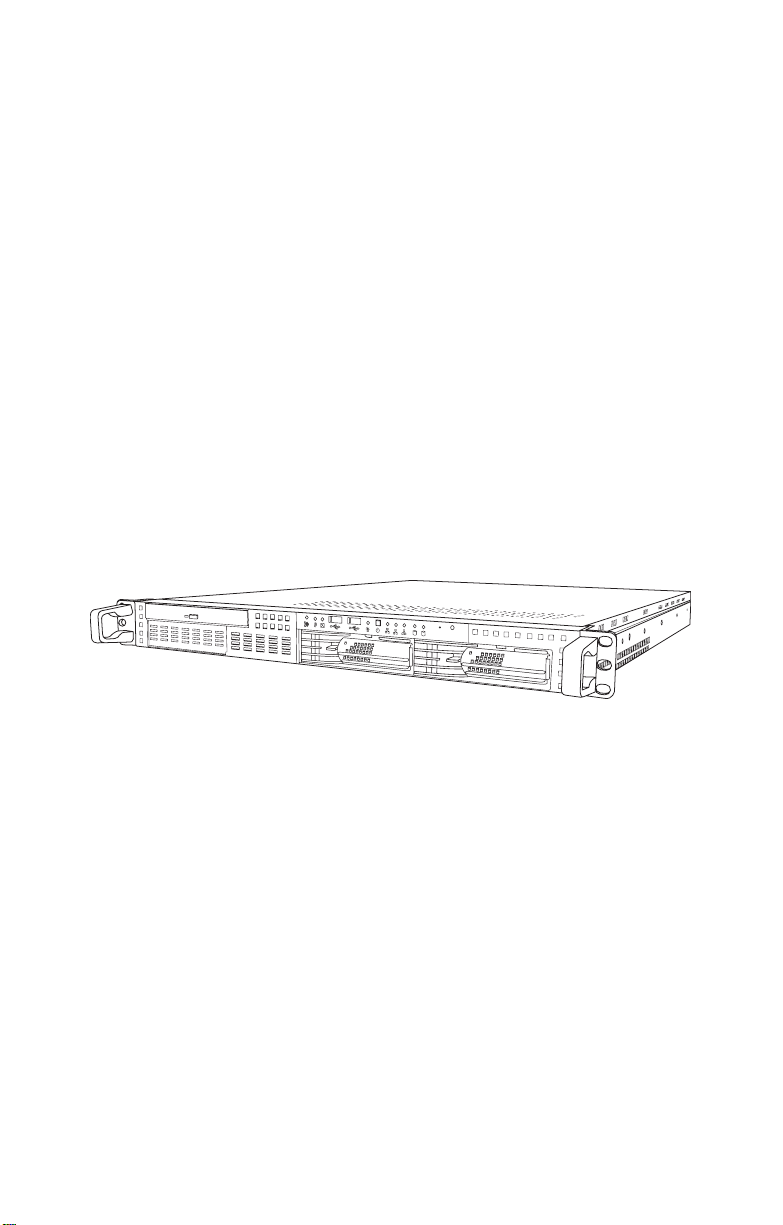
1.1 About the Transport GX21 B5102
Chapter 1: Overview
1.1 About the Transport GX21 B5102
Congratulations on your purchase of th e Transport GX21
B5102 rack mounted, barebone system for Intel®
Pentium® 4 processor. The Transport GX21 B5102 uses an
advanced Intel chipset for optimum performance and reliability. Integrated storage contoller and Gigabit Ethernet ports
combine to provide powerful computing capacity and optimal
I/O bandwidth for the most demanding enterprises.
The rugged, industry standard 19-inch, rack mountable
design contains 2 HDD bays, 1 slim CD-ROM bay and 1 3.5inch FDD or additional HDD bay making it both flexible and
practical.
1.2 System Requirements
There are 2 different SKUs of Transport GX21 .
Model
B5102G21S2
(OEM Only)
B5102G21S2H
(Standard)
HDD Tray
Type
Internal
(fixed)
Removable Yes
Hot-swap
Support
No No
HDD
Backplane
2-port
S-ATA
A choice of S-ATA and IDE HDD is possible with the
B5102G21S2 and the modular design makes installation of
new HDDs simple. S-ATA is a new HDD standard that uses
serial data transfer methods, unlike the traditional IDE
devices which rely on parallel data transfer.
Chapter 1: Overview 1
Page 10

1.3 Features
1.3 Features
Enclosure
• 1U, industry standard , 19 -inc h rackmountable chassis
• (2) HDD bays
• (1) slim CD-ROM bay
• (1) 3.5-inch bay for FDD or
additiona l HDD bay
• Dimension: D 21.5 x W 19 x H 1.7
inch (547x432x43 mm)
Processors
• Single ZIF PGA478 socket
• Supports one Intel® Pentium® 4
Northwood and Pre scott processor,
up to 3.2GHz
• Support 800/533/400MHz FSB
Chipset
• Intel 875P (Canterwood) MCH
• Intel 82801EB (ICH5) Sout h Br idge
• Winbond W83627HF Super I/O chip
Memory
• 128-bit dual channe l mem ory bus
• (4) DDR DIMM sockets
• Supports up to 4GB unbuffered
PC3200/2700/2100 DDR SDRAM
• Supports ECC/non-ECC ty pe memory modules
• Registered memory, not supported
Expansion Slots
(1) 32-bit/33MHz PCI slo t
Back I/O Ports
• Stacked PS/2 mouse/keyboard ports
• (2) USB 2.0 ports
• (1) 9-pin UART Serial port
• (3) RJ-45 LAN ports
• (1) VGA port
Front Panel Features
• I/O
(2) USB 2.0 ports
• LED indicators
– (1) IDE channel status LED
–(1) Power LED
– (1) FAN Fail LED
– (2) HDD acti vi ty LED
• Switch
– Power switch
– Reset switch
– Mute switch
Integrated Storage Controller
• Dual channel IDE
• Promise PDC20378 RAID
Accelerator, supports 2- port S-ATA
& 1 Ultra ATA-133 channel with
RAID 0, 1, 0+1
Storage
• B5102G21S2H: 2 x external access
drive bays
• B5102G21S2: 2 x in t er nal dr iv e
bays
• (1) slim type 24x CD-ROM drive
• (1)x Optional 3.5 " FD D
Networking
• (2) Gigabit Ethernet ports (Intel
82547EI GbE and 82541EI GbE
LAN controller)
• (1) 10/100 Mbps LAN port (Intel
82562EM controller)
Video
• ATI® Rage™ XL PCI graphics controller
• 8 MB Frame Buffer of video memory
BIOS
• Award® BIOS 8.0 on 4 Mbit LP C
Flash ROM
• Supports APM 1.2 & ACPI 1. 0
Motherboard
• TYAN Tomcat i875P S5102G3NR
motherboard
• ATX footprint (9.6 x 12-inch)
Power Supply
ATX12V, 1U, 300W with PFC
Cooling
• (5) 40x40x28mm, 11000rpm
• Power supply fan
• CPU heatsink
Regulatory
• FCC Class B (Declaration of Conformity)
• CE (Declaration of Conformity)
2 Chapter 1: Overview
Page 11
1.4 Unpacking
1.4 Unpacking
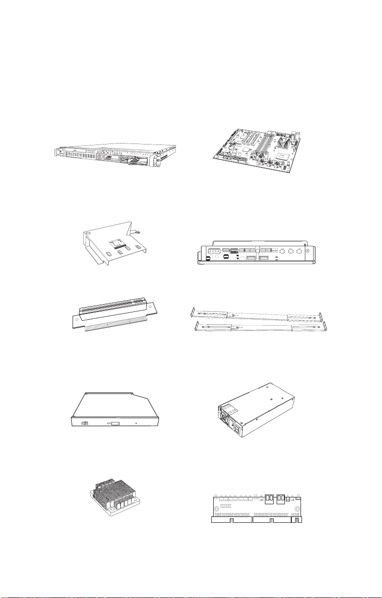
1.4.1 Box Contents (B5102G21S2H and B5102G21S2)
The following illustration displays all the components that
come with your Transport GX21 B5102 barebone system.
Ensue all items are present before begining installation
1
2
3
1
2
R
S
T
1
2
1U chassis. (2 external drive bays for
B5102G21S2H; 2 internal drive bays
for B5102G21S2) P/N 342730800001
1 x Air duct (pre installed)
P/N 412223700108
1 x 32 bit, 5V PCI riser card (pre installed).
P/N 412223700100
Slim CD-ROM Drive (pre installed).
P/N 52340061006
1 x Tomcat I875P-P4 S5012G3NR motherboard (pre installed). P/N 541172670026
ON KE
1
23456
1 x S-ATA backplane with 2 HDD trays
pre installed. (Not included with
B5102G21S2) P/N 412223700099
1 x sliding rail package with two sliding rails, plus mounting screws and
bracket.
P/N 341730200001
1 x ATX, 12V 300W 1U power supply,
(pre installed).
P/N 471172400035
1 x CPU Heatsink.
P/N 342730200001
1x LED control board (pre ins talled).
P/N 412223700102
Chapter 1: Overview 3
Page 12
1.4 Unpacking
h
ttp
://w
w
w
.tyan.c
om
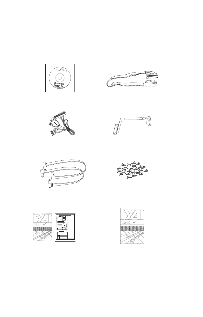
1.4.2 Accessories
If any items are missing or appear damaged, contact your
retailer or browse to TYAN’s Web site for service:
http://www.tyan.com.
The Web s ite also provides information on other TYAN products, plus FAQs, compatibility lists, BIOS settings, and more.
1 x Tyan driver CD
P/N 565172760103
1 x front panel cable (pre installed).
P/N 422730200002 (B5102G21S2H)
P/N 422730200001 (B5102G21S2)
2 x S-ATA cables, motherboard to
S-ATA board (pre installed).
P/N 422730200007
Jumpers
and
Tomcati875PS5102 BoardParts
CMOS Clear
JP3
1
High Performance Motherboard
User's Manual
Tomcat i875P
KB-MO1
Mouse(Top)
KB(Bottom)
USB1
LAN(Top)
USB(Bottom)
CN1
(COM1)
J2
(VGA)
LAN1
LAN2
(Optional)
S5102
#D 1528 - 100
Revision 1.0
J8 Front
Pin
Pin
P/N : 12-0012-3431
J6
CPU FAN
PWR1
lntel
10/100 LAN
lntel
lntel
GbE LAN
875P
S5102
DIMM1
DIMM2
DIMM3
DIMM4
32-bit 33MHz (5V)PCI PCI1
lntel
GbE LAN
(Optional)
32-bit 33MHz (5V)PCI PCI2
32-bit 33MHz (5V)PCI PCI3
USB2
USB3
ATI
8MB
RAGE XL
USB4
SDRAM
W83627HF
1
Chassls
J1
FAN
32-bit 33MHz (5V)PCI PCI4
COM2
J4
LPT1
J10
FDD
1
Panel Connector
2
1
PWR SPKR
PWR_LED
POWER
POWER
LED+
GND
GND
2
46810
1 3 5 7 9 11 13 15 17
HDD_LED+
HDD_LED-
GND
BUTTONBUTTON
RESET
RST
HD_LED
Normal
Pin 1-2 Close:
PWR2
(Default)
PGA478B
Pin 2-3 Close:
Claer
CMOS
CPU
Chassis FAN
J1
(via a cable)
COM2 port
J4
SMDC
(System
J5
Management Daughter
LED1
Connector
Card)
CPU FAN
J6
Connector
SMBus_0
J7
POWER
J9
FAN
J15
J13
CMOS
Serial ATA Connector
SATA1
JP3
lntel
1
(SATA3 / SATA4 by
SATA2
ICH5
PRI-IDE
SEC-IDE
PDC20378 Optional)
SATA3
LED2
SATA4
BIOS
1
Front USB Header
(via
USB2 /
1
an optional cable)
USB3 /
BT1
1
SATA1SATA2
USB4
EFI1
RAID-IDEJ12
PDC20378
POWER FAN
SATA3 SATA4
J8
J7
J9
SMDCJ5
18
17
SPEAKER
Power Supply
GND
GND
VCC
NC
S5102
is
The Tomcat
i875P
ATX
compatible.
ATXand 12V
12 14
16 18
ATX
2 power connectors:
(4-pin)
+
ATX12V
(20-pin)
VCC
CIRRX
IRRX
GND
IRTX
power connectors:
Manual for details
Check User's
IR
Rev.
1.00
http://www.TYAN.com
1 x 40 pin ATA33 IDE cable for CD-ROM (pre installed). P/N 422730200009
1 x 34 pin FDD cable.
P/N 422730200005
1 x spare screw pack.
1U 2-Way Server Platform
B2880T1S
Transport GX28
ID : 1540 - 100
Revision 1.0
Hardware
Installation Guide
Tomcat i875P S5102 motherboard quick reference guide
and user manual.
P/N 561572670002
1 x Transport GX21
hardware
Installation guide.
P/N 561872670002
4 Chapter 1: Overview
Page 13
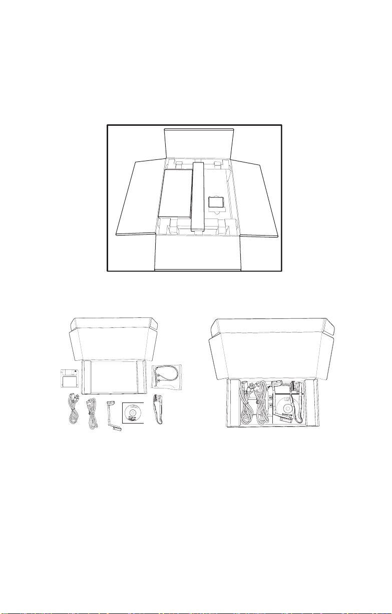
1.4.3 Opening the box
htt
p
:
/
/
ww
w
.
t
y
a
n.
co
m
h
t
t
p:
/
/
w
w
w
.
t
ya
n
.
c
o
m
Carefully open the box and ensure that all components are
present and undamaged. This product should arrive packaged as illustrated belo w.
Box contents as packaged (with heatsink)
1.4 Unpacking
Accessory Pack
(unpacked)
Chapter 1: Overview 5
Accessory pack (as packaged)
Page 14
1.5 About the Product
1.5 About the Product
The following views show you the product.
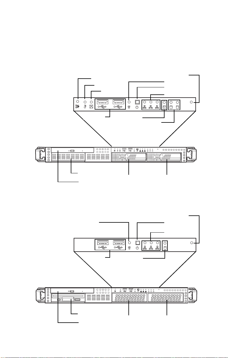
1.5.1 Front View
Model B5102G21S2H
USB ports
FDD (optional)
CD-ROM drive
Model B5102G21S2
Power LED
Mute LED
Temp fail LED
Fan fail LED
IDE channel
Reset
switch
Power LED
Power switch
LAN LEDs
1
3
status
2
HDD
1 2
RST
activity
1
3
2
1 2
RST
Hard drive bay 2 Hard drive bay 1
Reset
switch
Power switch
LAN LEDs
1
3
2
USB ports
1
IDE channel
RST
status
1
2
1
3
2
132
RST
1 2
RST
FDD (optional)
CD-ROM drive
Hard drive bay 2 Hard drive bay 1
6 Chapter 1: Overview
Page 15
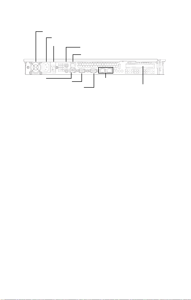
1.5.2 Rear View
Ventilation fan
ATX 12V 300W PSU
Power switch
1.5 About the Product
Stacked PS/2 mouse/keyboard ports
RJ-45 LAN ports
USB Ports
VGA port
Serial port
(COM1)
RJ-45 LAN ports
Expansion slot
Chapter 1: Overview 7
Page 16
1.5 About the Product
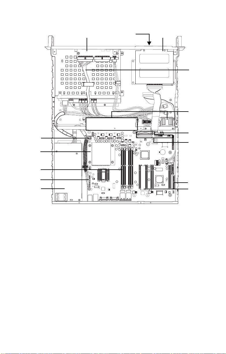
1.5.3 Internal View (B5102G21S2H) 1 23
9
10
4
5
6
7
8
1. LED control board
2. FDD (optional)
3. CD-ROM
4. ATX 12V power connector
(4 pin)
5. CPU/heatsink assembly
6. Memory slots x 4
7. Power connector
8. ATX 12V 300W power supply
(20 pin)
9. Front panel cable
10. 40x40x28 mm fans x 5
11
12
13
14
11. S-ATA hard drive connectors
x 2
12. IDE connectors x 3
13. FDD connector
14. 32-bit 5V riser card
8 Chapter 1: Overview
Page 17
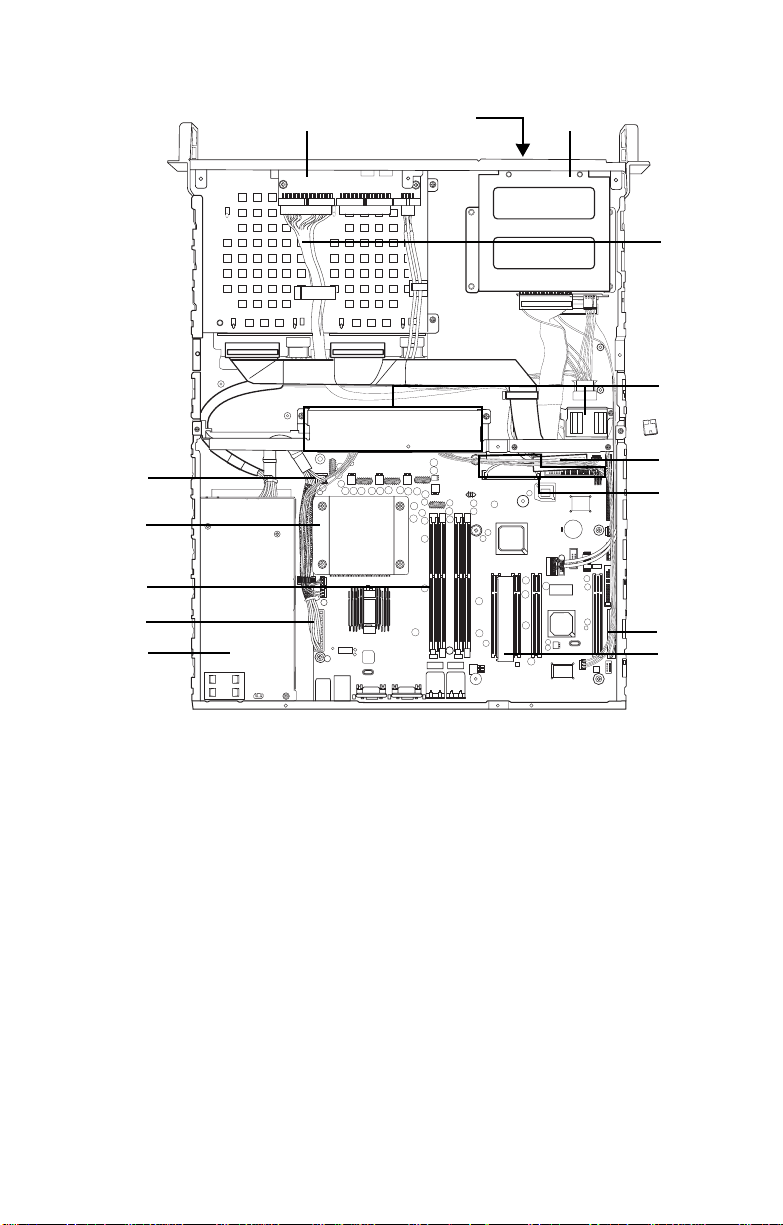
1.5.4 Internal View (B5102G21S2) 1 23
1.5 About the Product
9
10
4
5
6
7
8
1. LED control board
2. FDD (optional)
3. CD-ROM
4. ATX 12V power connector
(4 pin)
5. CPU/heatsink assembly
6. Memory slots x 4
7. Power connector
8. ATX 12V 300W power supply
(20 pin)
9. Front panel cable
11
12
13
14
10. 40x40x28 mm fans x 5
11. S-ATA hard drive connectors
x 2
12. IDE connectors x 3
13. FDD connector
14. 32-bit 5V riser card
Chapter 1: Overview 9
Page 18
1.5 About the Product
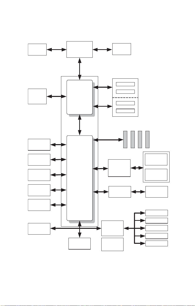
1.5.5 Motherboard Block Diagram
VRD10.0
CSA Interface
Intel 82547EI
Gigabit
Ethernet
USB 2.0
8 ports, 480Mb/s
2 X ATA 100/66/
33 Ports
2 X Serial ATA
Ports 150MB/s
Intel 82541EI
Gigabit Ethernet
(Optional)
800/533/400 MHz
266 MB/s
mPGA478
Processor Socket
System Bus
Intel 82875P MCH
Intel 82801EB
Intel 875P Chipset
266 MB/s
Hub Link 1.5
ICH5
Channel A
Channel B
PCI BUS
ICS-952607
Syatem Memory
DDR 400/333/266
Promise
PDC20378
RAID 0, 1, 0+1
ATI Rage XL
DDR
DDR
DDR
DDR
Four PCI Masters
2 X Serial ATA
RAID Ports
150MB/s
One ATA 133
IDE RAID Ports
1 x VGA
connector
Intel 82562EM
10/100 MB LAN
Keyboard
Mouse
Floppy
Parallel
Serial 1/2
Port 80 Post
Display
FirmWare Hub
LPC Interface
Winbond
W83627F/HF
LPC SIO
ADM1027
Hardware
Monitor
(optional)
10 Chapter 1: Overview
Page 19

2.1 Before You Begin
This chapter explains how to install the CPU, CPU heatsink,
memory modules, and hard drives. Instructions on inserting a
PCI card are a lso given.
Take note of the precautions mentioned in this section when
installing your system.
2.1.1 Work Area
Make sure you have a stable, clean working environment.
Dust and dirt can get into components and cause malfunctions. Use containers to keep small components separated.
Putting all small components in separate containers prevents
them from becoming lost. Adequate lighting and proper tools
can prevent you from accidentally damagi ng the inte rnal
components.
2.1.2 Tools
The following procedures require only a few tools, including
the following:
2.1 Before You Begin
Chapter 2: Setting Up
• A cross head (Phillips) screwdriver
• A grounding strap or an anti-static pad
Most of the electrical and mechanical connections can be disconnected using your fingers. It is recommended that you do
not use needle-nosed pliers to remove connectors as these
can damage the soft metal or plastic parts of the connectors.
Chapter 2: Setting Up 11
Page 20

2.1 Before You Begin
2.1.3 Precautions
Components and electronic circuit boards can be damaged
by discharges of static electricity. Working on a system that is
connected to a power supply can be extremely dangerous.
Follow the guidelines below to avoid damage to the
Transport GX21 or injury to yourself.
• Ground yourself properly before removing the top
cover of the system. Unplug the power from the
power supply and then touch a safely grounded
object to release static charge (i.e. power supply
case). If available, wear a grounded wrist strap. Alternatively, discharge any static electricity by touching
the bare metal chassis of the unit case, or the bare
metal body of any other grounded appliance.
• Avoid touching motherboard components, IC chips,
connectors, memory modules, and leads.
• The motherboard is pre-installed in the system.
When removing the motherboard, always place it on
a grounded anti-static surface until you are ready to
reinstall it.
• Hold electronic circuit board s by the edge s onl y. Do
not touch the components on the board unless it is
necessary to do so. Do not flex or stress circuit
boards.
• Leave all components inside the static-proof packag-
ing that they ship with until they are ready for installation.
• After replacing optional devices, make sure all
screws, springs, or other small parts are in place and
are not left loose inside the case. Metallic parts or
metal flakes can cause electrical shorts.
Notes:
• All connectors are keyed to only attach one w ay.
• Always use the correct screw size as indicated in the
procedures.
12 Chapter 2: Setting Up
Page 21
2.2 Rack Mounting
The Transport GX21can be mounted in a rack using the supplied rack mounting kit.
Rack mounting kit
Sliding Rails x 2:
Standard Mounting Brackets x 4
Mounting Ears x 2
Nuts, Screws and Washers Kit x 1
2.2.1 Installing the Server in a Rack
Follow these instructions to mount the Transport GX21
B5102 into an industry standard 19" rack
Before mounting the Transport GX21 in a rack, ensure that all
internal components have been installed and that the unit has
been fully tested. Maintenance can be performed on the unit
while in a rack but it is preferable to install the device in a fully
operational condition.
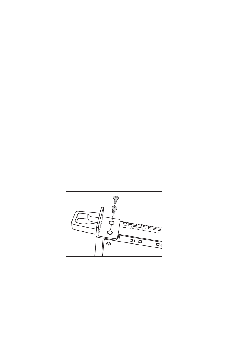
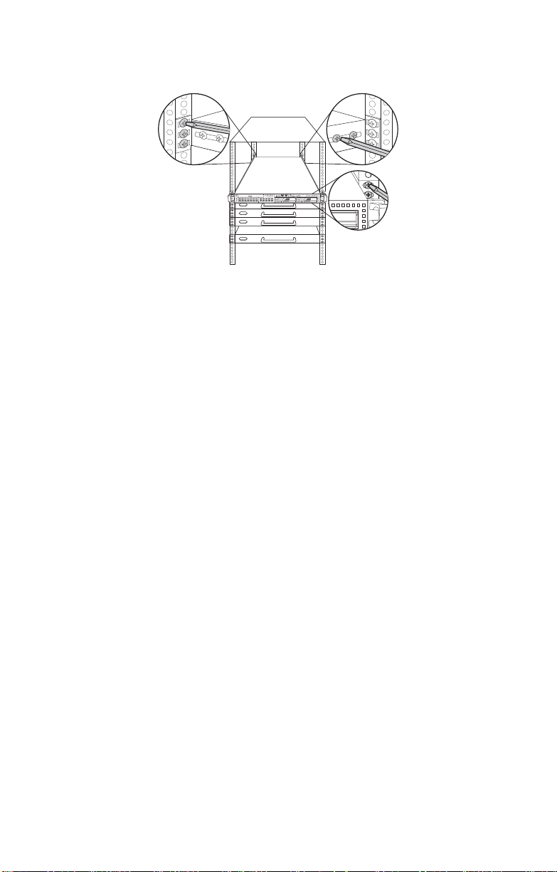
1. Screw the mounting ears to the Transport GX21 as shown using 4 screws from the supplied nuts, screws and washers kit.
2.2 Rack Mounting
Chapter 2: Setting Up 13
Page 22
2.2 Rack Mounting
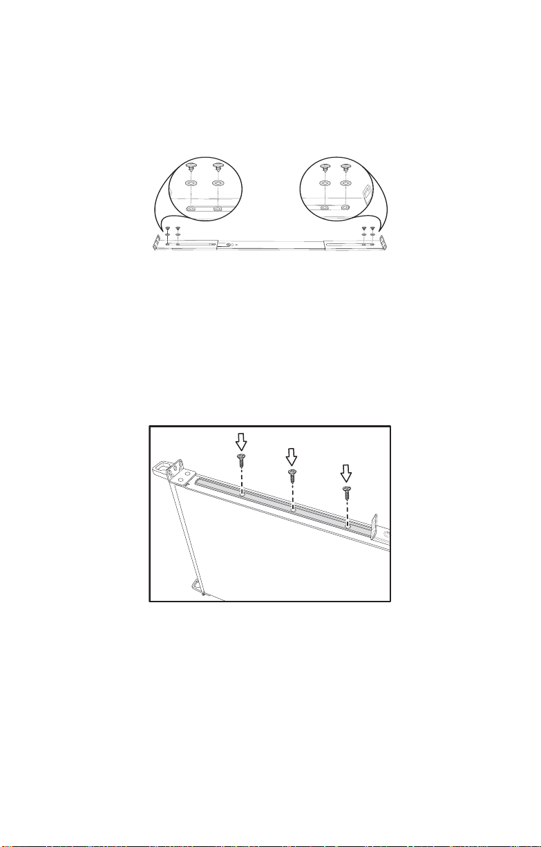
2. Screw the sliding rail mounting brackets to the sliding
rails as shown, using the short black screws from the
supplied nuts, screws and washers kit. Ensure that the
brackets with the cut away section (to accommodate the
handles on the front of the unit) are fixed to the front end
of the rail.
Note: Do not tighten the brackets to the
rails as you will need to adjust their position
later.
3. Fully extend the sliding rails until they lock.
4. Screw each sliding rail to the side of the Transport GX21 as shown. You will need 3 short, silver colored screws from the supplied nuts, screws and washers kit, for each rail.
5. Return the sliding rails to their shortest position.
14 Chapter 2: Setting Up
Page 23
2.2 Rack Mounting
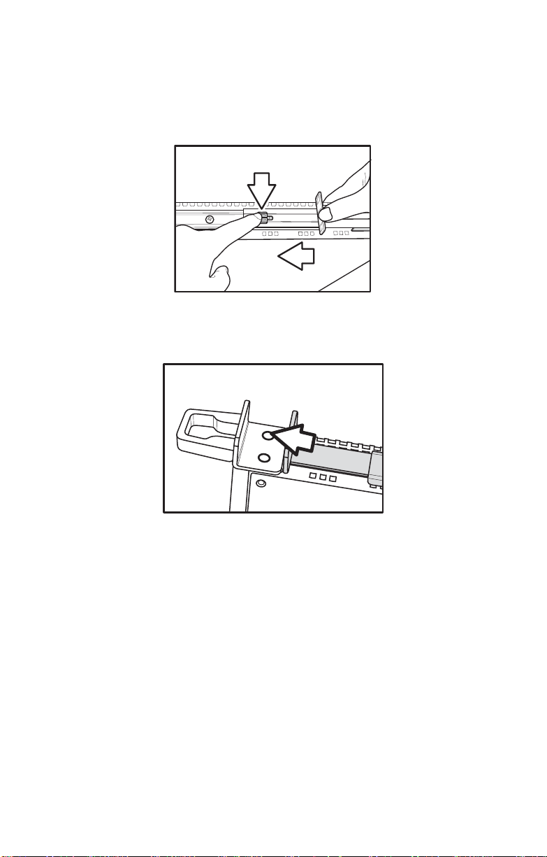
Note: When fully extended, the sliding rails
will lock. The release mechanism is located
on the sliding rail as shown. Press the
release mechanism while pushing the sliding
rails to shorten them.
6. With the rails in their shortest condition, adjust both front mounting brackets so that they are flush with the front of the unit.
7. Accurately measure the depth of your rack and adjust the rear brackets accordingly.
8. When all brackets are positioned correctly, tighten them.
Chapter 2: Setting Up 15
Page 24
2.2 Rack Mounting
9. Lift the unit into place in the rack and screw it into place as shown.
Note: To avoid injury , it is strongly recom-
mended that two people lift the
Transport GX21into place while a third person screw it to the rack.
1
2
132
RST
16 Chapter 2: Setting Up
Page 25
2.3 Installing Motherboard Components
2.3 Installing Motherboard Components
This section describes how to install components on to the
motherboard, including CPU, memory modules and PCI card.
2.3.1 Removing the Chassis Cover
Follow these instructions to remove the Transport GX21
chassis cover.
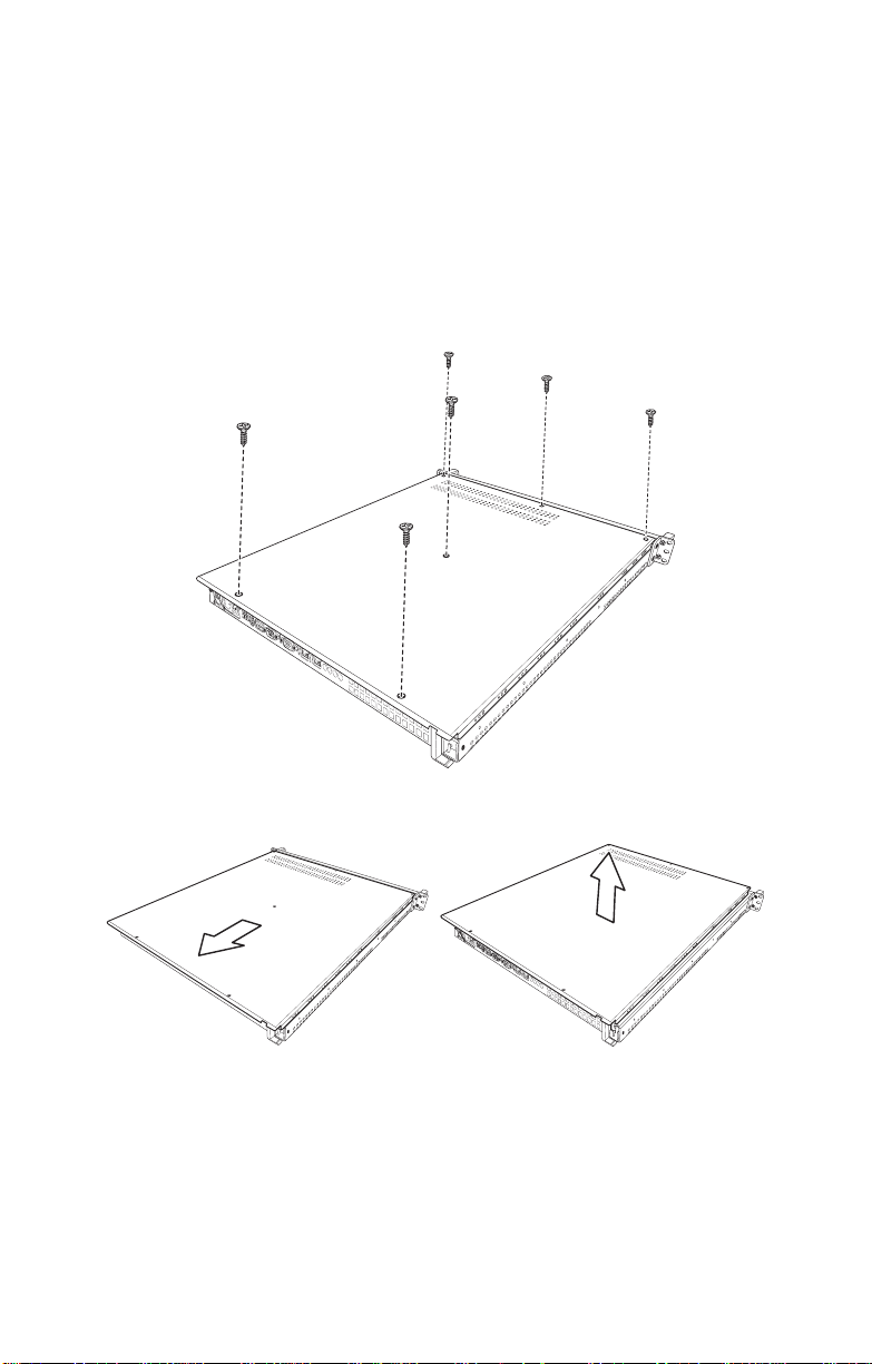
1. Remove the six screws securing the chassis cover.
2. Slide the cover in the direction of the arrow (A) and then lift the cover off (B).
A
Chapter 2: Setting Up 17
B
Page 26
2.3 Installing Motherboard Components
2.3.2 Installing a CPU, Heatsink and Air Duct
Follow these instructions to install a CPU, CPU heatsink and
air duct.
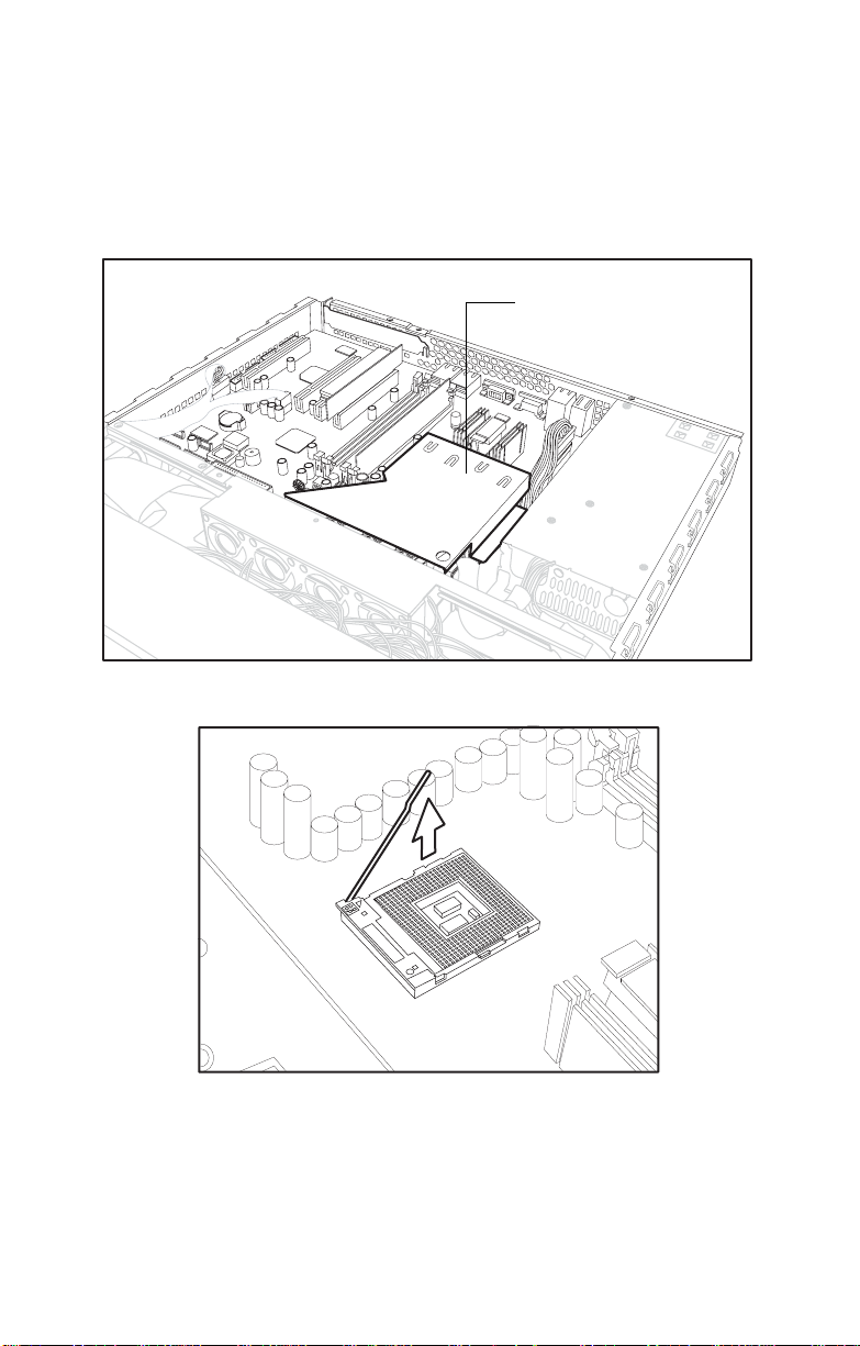
1. Remove the pre-installed air duct. Refer to the illustration on top of the air duct to locate the 2 screws.
CPU socket under air duct
2. Pull the CPU lever up to unlock the CPU socket.
18 Chapter 2: Setting Up
Page 27
2.3 Installing Motherboard Components
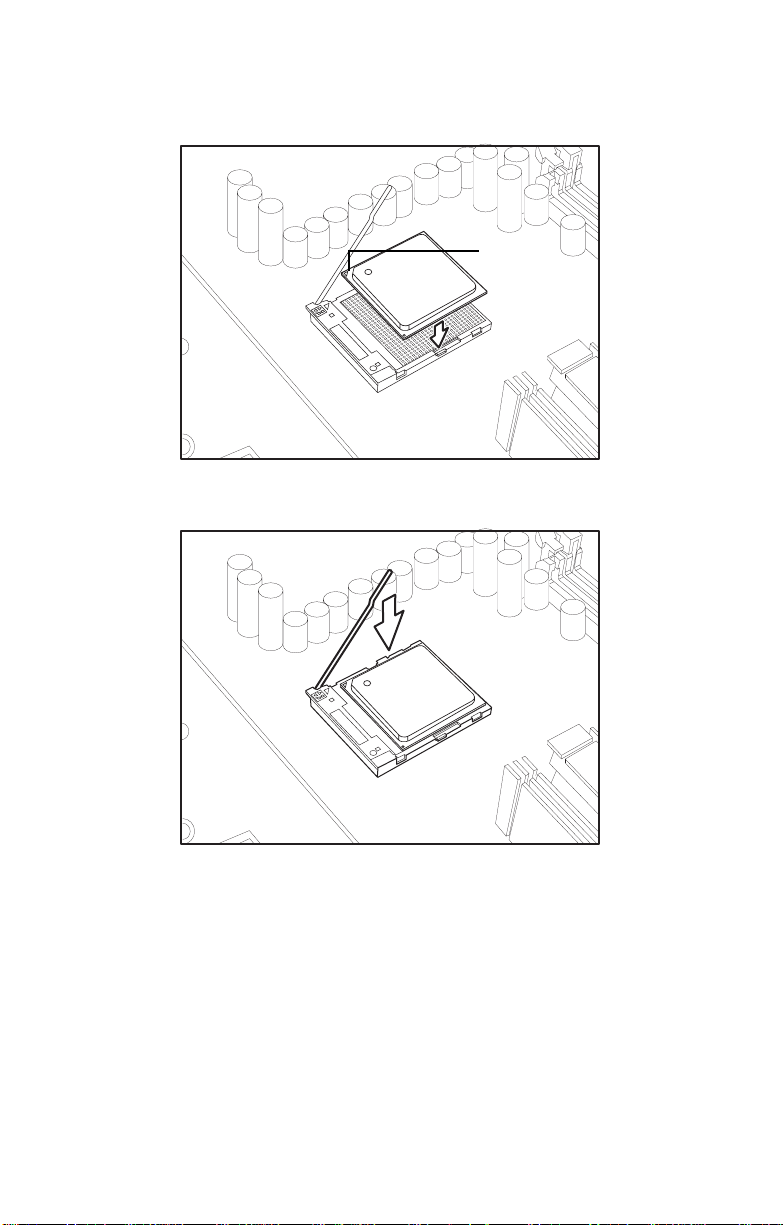
3. Place the CPU in the CPU socket, ensuring that pin 1 is located as shown in the following il lustr ati on .
Pin 1
4. Press the CPU socket lever down in the direction shown to secure the CPU.
5. Apply thermal grease to the top of the CPU and place the CPU heatsink on the CPU.
Chapter 2: Setting Up 19
Page 28
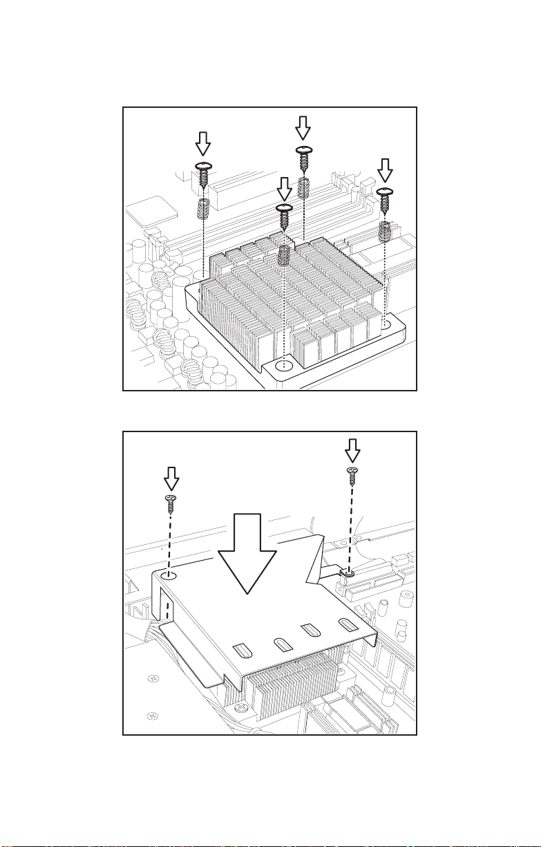
2.3 Installing Motherboard Components
6. Align the heatsink screw holes with the holes on the motherboard and insert the four heatsink screws as shown.
7. Place the air duct over the heatsink and replace the heat shield screws to secure it to the motherboard.
20 Chapter 2: Setting Up
Page 29
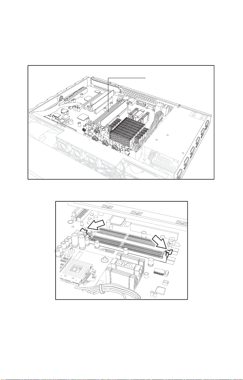
2.3.3 Installing Memory
Follow these instructions to install memory modules on the
motherboard.
1. Locate the memory slots on the motherboard.
2. Press the memory slot locking levers in the direction of the arrows as shown in the following illustration.
2.3 Installing Motherboard Components
Memory slo ts
3. Align the memory module with the slot; the module has indentations that align with notches in the slots.
Chapter 2: Setting Up 21
Page 30
2.3 Installing Motherboard Components
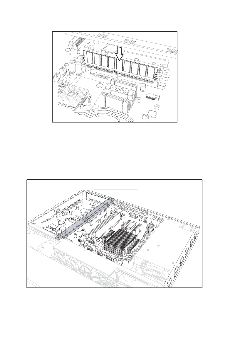
4. Insert the memory module into the slot as shown.
When inserted properly, the memory slot locking levers lock
onto the indentations at the ends of the module.
2.3.4 Installing a PCI Card
Follow these instructions to install a PCI card.
1. Remove the pre-installed PCI retention bar
PCI riser card
22 Chapter 2: Setting Up
Page 31

2.3 Installing Motherboard Components
2. Remove the screw securing the PCI faceplate to the chassis.
3. Slide the PCI card clamp out as shown.
4. Slide the dust cover out.
Chapter 2: Setting Up 23
Page 32

2.3 Installing Motherboard Components
5. Slide the PCI card into place and then insert it into the
PCI slot on the riser card. Ensure that it is inserted correctly.
Insert PCI card tip in slot here.
Riser Card
6. Reinsert the PCI card clamp.
24 Chapter 2: Setting Up
Page 33

2.3 Installing Motherboard Components
7. Insert the screw to secure the PCI card to the chassis.
Chapter 2: Setting Up 25
Page 34

2.4 Installing a Hard Drive
2.4 Installing a Hard Drive
The Trasport GX21 barebone system supports both Serial
ATA and IDE hard drives. However, if you have purchased
the B5102G21S2H model with pre-installed S-ATA
backplane, only S-A TA hard drives can be used.
2.4.1 Installing an External Access S-ATA Hard Disk Drive
Follow these instructions to install a S-ATA hard drive.
1. Press the drive bay locking lever latch in the direction of the arrow (1) and pull the locking lever open (2).
1
2
3
1
2
R
S
T
1
2
2. Slide the drive bay out.
1
2
3
1
2
R
S
T
3. Place an S-ATA hard drive into the drive bay.
26 Chapter 2: Setting Up
Page 35

2.4 Installing a Hard Drive
4. Insert hard drive screws to secure the hard drive to the drive bay.
5. Reinsert the drive bay into the chassis, ensuring that the
HDD rear connector is securely connected to the backplane connector.
1
2
3
1
2
R
S
T
Chapter 2: Setting Up 27
Page 36

2.4 Installing a Hard Drive
2.4.2 Installing an Internal IDE or S-ATA Hard Disk Drive
Follow these instructions to install an IDE or S-ATA hard
drive.
1. Remove the IDE or S-ATA data cable and power connector from the HDD.
2. Remove the screw securing the HDD tray to the chassis.
3. Slide the HDD tray out.
28 Chapter 2: Setting Up
Page 37

2.4 Installing a Hard Drive
4. Place an IDE or S-AT A HDD into the tray , and secure with 4 screws.
5. Reinsert the HDD tray and secure with a screw.
6. Connect the IDE or S-ATA data cable and power cable connector to the HDD.
Chapter 2: Setting Up 29
Page 38

2.4 Installing a Hard Drive
30 Chapter 2: Setting Up
Page 39

Chapter 3: Replacing Pre-Installed
3.1 Introduction
This chapter explains how to replace pre installed components including the motherboard, LED control board, FDD
and CD-ROM drive. There is also a section showing how to
replace a FFD with a HDD.
Take note of the precautions in this section when installing
your system.
3.1.1 Work Area
Make sure you have a stable, clean working environment.
Dust and dirt can get into components and cause malfunctions. Use containers to keep small components separated.
Putting all small components in separate containers keeps
them from becoming lost. Adequate lighting and proper tools
can prevent you from accidentally damagi ng the inte rnal
components.
3.1 Introduction
Components
3.1.2 Tools
The procedures that follow require only a few tools, including
the following:
• A cross head (Phillips) screwdriver
• A grounding strap or an anti-static pad
Most of the electrical and mechanical connections can be disconnected using your fingers. It is recommended that you do
not use needle-nosed pliers to remove connectors as these
can damage the soft metal or plastic parts of the connectors.
Chapter 3: Replacing Pre-Installed Components 31
Page 40

3.1 Introduction
3.1.3 Precautions
Components and electronic circuit boards can be damaged
by static electricity . Working on a system that is connected to
a power supply can be extremely dangerou s. Foll ow the
guidelines below to avoid damage to the Transport GX21 or
injury to yourself.
• Ground yourself properly before removing the top
cover of the system. Unplug the power from your
computer power supply and then touch a safely
grounded object to release static charge (i.e. power
supply case). If available, wear a grounded wrist
strap. Alternatively , discharge any static electricity by
touching the bare metal chassis of the unit case, or
the bare metal body of any other grounded appliance.
• Avoid touching motherboard components, IC chips,
connectors, memory modules, and leads.
• The motherboard is pre-installed in the system.
When removing the motherboard, always place it on
a grounded anti-static surface until you are ready to
reinstall it.
• Hold electronic circuit board s by the edge s onl y. Do
not touch the components on the board unless it is
necessary to do so. Do not flex or stress circuit
boards.
• Leave all components inside the static-proof packag-
ing that they ship with until they are ready for installation.
• After replacing optional devices, make sure all
screws, springs, or other small parts are in place and
are not left loose inside the case. Metallic parts or
metal flakes can cause electrical shorts.
Notes:
• All connectors are keyed to only attach one w ay.
• Always use the correct screw size as indicated in the
procedures.
32 Chapter 3: Replacing Pre-Installed Components
Page 41

3.2 Disassembly Flowchart
The following flowchart outlines the disassembly procedure.
Rear Components
Chassis cover
CPU/heatsink assembly
Air duct
Mainboard
Power supply
Front Components
Chassis cover
3.2 Disassembly Flowchart
DIMMs
PCI card
Mainboard
Cooling Fan Assembly
LED control board
Cooling Fan
S-ATA Backplane
PCBs
CD-ROM
FDD
Chapter 3: Replacing Pre-Installed Components 33
Page 42

3.3 Removing the Cover
3.3 Removing the Cover
Before replacing any parts you must remove the chassis
cover.
Follow these instructions to remove the cover of the
Transport GX21 chassis cover.
1. Remove the six screws securing the chassis cover.
2. Slide the cover in the direction of the arrow (A) and then lift the cover off (B).
A
34 Chapter 3: Replacing Pre-Installed Components
B
Page 43

3.4 Replacing Motherboard Components
3.4 Replacing Motherboard Components
Follow these instructions to replace motherboard components, including the motherboard.
3.4.1 Removing Add-On Components from the Motherboard
Before removing the motherboard, remove the CPU, memory
modules, disconnect all cables and remove the PCI card if
you have one installed.
Follow these instructions to remove the mainboard.
1. Remove the riser card retention bar as shown below.
2. Remove the PCI riser card.
Chapter 3: Replacing Pre-Installed Components 35
Page 44

3.4 Replacing Motherboard Components
3.4.2 Disconnecting Cables
Disconnect all the cables on the board
1. Disconnect the main and ATX power cables.
Main powerATX12V power
2. Disconnect the CD-ROM (A) and S-ATA hard drive (B) cables.
A
B
36 Chapter 3: Replacing Pre-Installed Components
Page 45

3.4 Replacing Motherboard Components
Note: If an FDD or IDE HDD is installed,
you must disconnect these cables too.
3. Disconnect the front panel switch/LED connector.
4. Disconnect the front panel USB connector.
Chapter 3: Replacing Pre-Installed Components 37
Page 46

3.4 Replacing Motherboard Components
3.4.3 Removing the Motherboard
Follow these instructions to remove the motherboard from the
chassis when all add-on components have been removed.
1. Remove the 8 screws securing the motherboard to the chassis.
2. Remove the motherboard.
38 Chapter 3: Replacing Pre-Installed Components
Page 47

3.5 Replacing the CD-ROM/FDD
3.5 Replacing the CD-ROM/FDD
Follow these instructions to replace the CD-ROM or FDD.
1. Remove the data cable from the slim CD-ROM adapter.
2. Remove the power cable from the slim CD-ROM adapter.
3. Remove the 2 screws that secure the adapter board to the slim CD-ROM and lift it free from the chassis.
Chapter 3: Replacing Pre-Installed Components 39
Page 48

3.5 Replacing the CD-ROM/FDD
4. Remove the 4 screws securing the drive bay to the chassis.
5. Lift the drive bay free from the chassis.
6. Remove the 4 small screws securing the CD-ROM or FDD in the drive bay.
7. Slide the CD-ROM or FDD from the drive bay.
40 Chapter 3: Replacing Pre-Installed Components
Page 49

3.6 Replacing the FDD with a HDD
3.6 Replacing the FDD with a HDD
Follow these instructions to replace the FDD with a HDD
1. Remove the power and data cables from the back of the CD-ROM drive and FDD.
Note: Unless you are intending to replace
the CD-ROM drive, there is no need to
remove the CD-ROM backplane.
2. Remove the 4 screws that secure the drive bay housing to the chassis.
Chapter 3: Replacing Pre-Installed Components 41
Page 50
3.6 Replacing the FDD with a HDD
3. Slide the drive bay housing backwards and lift it clear of the chassis.
4. Remove the 4 screws that secure the FDD in the drive bay and lift it free of the drive bay housing.
5. Place a HDD in the drive bay housing and secure with 4 screws. Refer to section 2.4.2 In stalling an Intern al IDE or S-ATA Hard Disk Drive for details on installing a hard disk.
6. Replace the drive bay housing in the chassis and secure with 4 screws.
7. Replace the powe r and data cable s for the CD-ROM drive and the new HDD unit.
42 Chapter 3: Replacing Pre-Installed Components
Page 51

3.7 Replacing the LED Control Board
3.7 Replacing the LED Control Board
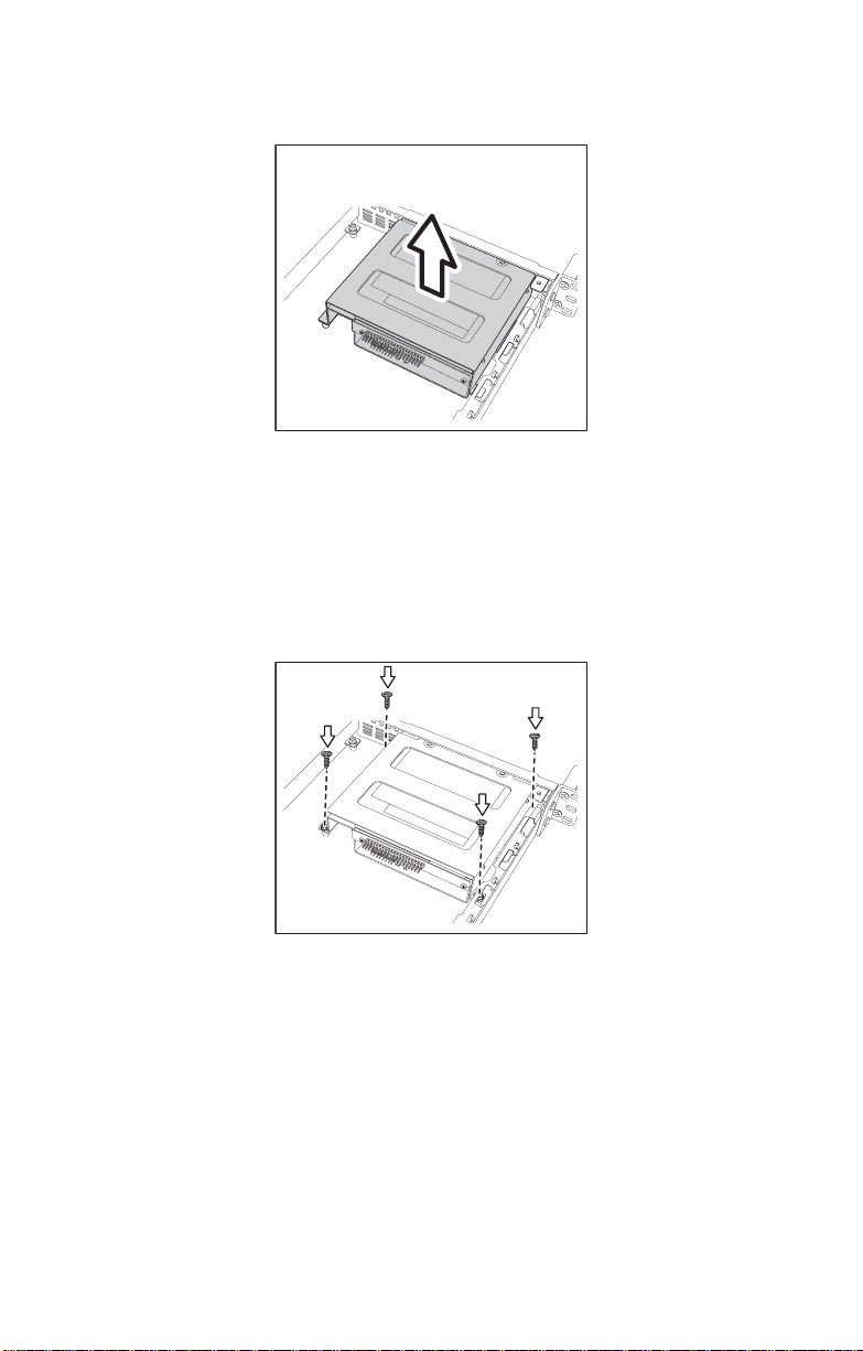
Follow these instructions to remove the LED control board.
1. Remove the 2 screws securing the metal retaining plate to the chassis.
2. Lift the retaining plate free of the chassis, as shown below.
3. Unplug the front panel ribbon cable connector from the rear of the LED control panel.
4. Unplug the other end of the ribbon cable from the backplane of the HDD as shown...
5. Lift the ribbon cable free from the chassis.
Chapter 3: Replacing Pre-Installed Components 43
Page 52

3.8 Replacing the S-ATA Backplane
6. Remove the 2 screws securing the LED control board to the chassis.
7. Lift the LED control board free from the chassis.
3.8 Replacing the S-ATA Backplane
Note: This section appllies to
B5102G21S2H model only.
1. Remove the 2 screws securing the metal retaining plate to the chassis and lift the retaining plate free.
2. Remove the cables from the rear of the S-ATA back plane.
44 Chapter 3: Replacing Pre-Installed Components
Page 53

3.8 Replacing the S-ATA Backplane
3. Remove the 5 screws that secure the backplane bracket to the chassis.
4. Lift the backplane bracket free from the chassis as shown
Chapter 3: Replacing Pre-Installed Components 45
Page 54

3.8 Replacing the S-ATA Backplane
A
P
3.8.1 2 Port S-ATA Backp lane Fe atu res
U1 monitor fan1,
fan2 temperature
U2 monitor fan3,
fan4
U3 monitor fan5
J6 12C connector
Fan 5 connector
Fan 4 connector
Fan 3 connector
Fan 2 connector
Fan 1 connector
function set switch
1 LED pin output, 2
x 6 pin header
ON KE
23456
1
J3 serial ATA7 pin connector
J4 HDD2 serial AT
7 pin connector
BZ1 buzzer
J5 DC power input
connector
46 Chapter 3: Replacing Pre-Installed Components
Page 55

3.9 Replacing the Power Supply
3.9 Replacing the Power Supply
1. Remove the 4 screws that secure the fa n assembly to t he chassis.
2. Lift the fan assembly clear to give access to the power supply cables.
3. Remove power cables from the motherboard, HDDs and FDD if installed.
Chapter 3: Replacing Pre-Installed Components 47
Page 56

3.9 Replacing the Power Supply
4. Remove the 2 screws from the mounting bracket that secure the power supply to the chassis.
5. Remove the 2 scre ws fr om the p ower supply rear bracke t that secure it to the chassis.
6. Lift the power supply clear of the chassis.
7. Remove the 2 screws that secure the power supply bracket to the power supply and remove the bracket.
48 Chapter 3: Replacing Pre-Installed Components
Page 57

3.10 Replacing the Cooling Fans
3.10 Replacing the Cooling Fans
Follow these instructions to replace the cooling fans.
1. Remov e all the co oling fan powe r sup pl y cables.
Note: Cooling fan power supply cables are
connected to the motherboard in the
B5102G21S2 model, and to the S-ATA backplane in the B5102G21S2H model. Refer to
the following diagrams for details.
B5102G21S2H cooling fan power supply connections:
B5102G21S2 cooling fan power supply connections:
Chapter 3: Replacing Pre-Installed Components 49
Page 58

3.10 Replacing the Cooling Fans
Note: To lift the fan assembly clear of the
chassis, you may fin d it necessa ry to remove
the plastic cable ties which secure the fan
cables.
2. Remove the 2 screws which secure t he cooling fan bracket to the chassis.
3. Lift the cooling fan assembly from the chassis.
50 Chapter 3: Replacing Pre-Installed Components
Page 59

3.10 Replacing the Cooling Fans
4. Remove the 4 screws that secure each cooling fan to the cooling fan bracket.
5. Lift the cooling fan clear of the bracket.
6. Repeat step 5 until all the necessary cooling fans have been removed from the cooling fan bracket.
Chapter 3: Replacing Pre-Installed Components 51
Page 60

3.10 Replacing the Cooling Fans
52 Chapter 3: Replacing Pre-Installed Components
Page 61

Appendix
BIOS Setup
Installation
The BIOS is the basic input/output system, the firmware on
the motherboard that enables your hardware to interface with
your software. The BIOS determines what a computer can do
without accessing programs from a disk. The BIOS contains
all the code required to control the keyboard, display screen,
disk drives, serial communications, and a number of miscellaneous functions. This chapter describes the various BIOS
settings that can be used to configure your system.
The BIOS section of this manual is subject to change without
notice and is provided for reference purposes only. The settings and configurations of the BIOS are current at the time of
print and are subject to change, and therefore may not match
exactly what is displayed on screen.
This section describes the BIOS setup program. The setup
program lets you modify basic configuration settings. The settings are then stored in a dedicated, battery-backed memory
(called NVRAM) that retains the information even when the
power is turned off.
This motherboard’s BIOS is a customized versi on of the
industry-standard BIOS for IBM PC AT-compatible personal
computers. The BIOS provides critical, low-level support for
the system’s central processing unit (CPU), memory, and I/O
subsystems.
This BIOS has been customized by adding important features
such as virus and password protection, power management,
and chipset “tuning” features that control the system. This
section will guide you through the process of configuring the
BIOS for your system setup.
53
Page 62

Starting Setup
The BIOS is immediately activated when you turn on the
computer. The BIOS reads system configuration in CMOS
RAM and begins the process of checking the system and
configuring it through the Power-On-Self-Test (POST).
When the preliminary tests are complete, the BIOS searches
for an operating system on one of the system’s data storage
devices (hard drive, CD-ROM, etc). If an operating system is
found, the BIOS will launch that operating system and hand
over control to it. You can enter the BIOS setup by pressing
the [Delete] key when the machine boots up and begins to
show the memory count.
Setup Basics
The table below shows how to navigate the setup program
using the keyboard.
Table 1: Navigation Keys
Key Function
T ab Moves from one selection to the
next
Left/Right
Arrow Keys
Up/Down
Arrow Keys
Enter Opens highlighted section
PgUp/PgDn
Keys
Change from one menu to the
next
Move between selections
Change settings.
Getting Help
Pressing [F1] will display a small help window that describes
the appropriate keys to use and the possible selections for
the highlighted item. To exit the Help Window, press [ESC] or
the [F1] key again.
54
Page 63

In Case of Problems
If you have trouble booting your computer after making and
saving the changes with the BIOS setup program, you can
restart the computer by holding the power button down until
the computer shuts off (usually within 4 seconds); resetting
by pressing CTRL-ALT-DEL; or clearing the CMOS.
The best advice is to only alter settings that you thoroughly
understand. In particular, do not change settings in the
Chipset section unless you are absolutely sure of wha t you
are doing. The Chipset defaults have been carefully chosen
either by TYAN or your system manufacturer for best performance and reliability. Even a seemingly small change to the
Chipset setup options may cause the system to become
unstable or unusable.
Differences in Setup
Not all systems will have the same BIOS setup layout or
options. While the basic look and function of the BIOS setup
remains more or less the same for most systems, the appearance of your Setup screen may differ from the charts shown
in this document. Each system design and chipset combination requires a custom configuration. In addition, the final
appearance of the Setup program depends on the system
designer. Y our system designer may decide that certain items
should not be available for user configuration, and may
remove them from the BIOS setup program.
Note: On the following pages, options writ-
ten in bold type represent the BIOS Setup
default.
55
Page 64

BIOS Setup - Main Screen
The Phoenix - AwardBIOS CMOS Setup Utility main screen
is displayed as follows:
Phoenix – AwardBIOS CMOS Setup Utility
XStandard CMOS Features
XAdvanced BIOS Features
XAdvanced Chipset Features
XIntegrated Peripherals
XPower Management Setup
XPnP/PCI Configurations
XPC Health Status
Esc: Quit ↑ ↓ ← →: Select Item
F10: Save & Exit Setup
Time, Date, Hard Disk Type
Standard CMOS Features
XFrequency/Voltage Control
XLoad Fail-Safe Defaults
XLoad Optimized Defaults
XSet Supervisor Password
XSet User Password
XSave & Exit Setup
XExit Without Saving
Use this menu for basic system configuration.
Advanced BIOS Features
Use this menu to set the advanced features available on your
system.
Advanced Chipset Features
Use this menu to change the values in the chipset registers
and optimize your system's performance.
Integrated Peripherals
Use this menu to specify your settings for integrated peripherals.
Power Management Setup
Use this menu to specify your settings for power management.
PnP / PCI Configuration
Use this menu to view and set PCI and PnP options.
PC Health Status
Use this menu to show your system temperature, speed and
voltage status.
Frequency/Voltage Control
Use this menu to specify your settings for frequency/voltage
control.
56
Page 65

Load Fail-Safe Defaults
Use this menu to load the BIOS default values for the minimal/stable performance settings for your system to operate.
Load Optimized Defaults
Use this menu to load the BIOS default values that are factory settings for optimal performance of system operations.
While Award has designed the custom BIOS to maximize
performance, the factory has the right to change these
defaults to meet their needs.
Supervisor / User Password
Use this menu to set User and Supervisor Passwords.
Save & Exit Setup
Save CMOS value changes to CMOS and exit setup.
Exit Without Save
Abandon all CMOS value changes and exit setup.
57
Page 66

Standard CMOS Features
In this section, you can alter general features such as the
date and time, as well as access to the IDE configuration
options. Note that the options listed below are for settings
that can be directly changed within the Main Setup screen.
Y ou can use the arrow keys to highlight the item and then use
the <PgUp> or <PgDn> keys to select the value you want in
each item.
Phoenix – AwardBIOS CMOS Setup Utility
Standard CMOS Features
Date (mm: dd: yy)
Time (hh: mm: ss)
IDE Channel 0 Master
X
IDE Channel 0 Slave
X
IDE Channel 1 Master
X
IDE Channel 1 Slave
X
IDE Channel 2 Master
X
IDE Channel 3 Master
X
Drive A
Drive B
Video
Halt On
Based Memory
Extended Memory
Total Memory
↑↓←→: Move
F1: General Help
F5: Previous Values
Enter: Select
Thu, Apr 3 2003
13: 31: 30
[None]
[None]
[None]
[None]
[None]
[None]
[1.44M, 3.5 in.]
[None]
[EGA/VGA]
[All Errors]
640K
64512K
65536K
+/-/PU/PD: Value
F6: Fail-Safe Defaults
Item Help
______________________
Menu Level
Change the day, month,
year and century
F10: Save
F7: Optimized Defaults
X
ESC: Exit
58
Page 67

Date / Time Setup
System Date: Adjusts the system date.
MMMonths
DDDays
YYYYYears
System Time: Adjusts the system clock.
HHHours (24hr. format)
MMMinutes
SSSeconds
IDE Master / Slave Setup
With this option the computer detects IDE drive types from
drive C to drive F. The choices are:
None / Auto / Manual
Drive A / B:
This option defines the floppy drive type. The choices are:
None / 360K, 5.25in / 1.2M, 5.25in / 720K, 3.5in
/ 1.44M, 3.5in / 2.88M, 3.5in
Video:
This option defines the video display mode. The choices are:
EGA/VGA / CGA 40 / CGA 80 / MONO
Halt On:
This option determines whether the computer should stop
booting when an error is detected during power up. The
choices are:
No Errors / All Errors / All, But Keyboard / All,
But Diskette / All, But Disk/Key
59
Page 68

Advanced BIOS Features
In this section, you can fine tune features that affect system
speed and boot-up options.
Phoenix – AwardBIOS CMOS Setup Utility
Advanced BIOS Features
Virus Warning
CPU L1 & L2 Cache
Hyper-Threading Technology
Quick Power On Self Test
XBoot Sequence
Boot Up NumLock Status
Gate A20 Option
Typematic Rate Setting
X Typematic Rate (Chars/Sec)
X Typematic Delay (Msec)
Security Option
APIC Mode
MPS Version Control For OS
OS Select For DRAM > 64MB
HDD S.M.A.R.T Capability
Report No FDD For WIN 95
Small Logo (EPA) Show
↑↓←→: Move
F5: Previous Values
Enter: Select
+/-/PU/PD: Value
F6: Fail-Safe Defaults
Virus Warning
This option toggles virus protection on or off for boot sector
writes. If this function is enabled, the BIOS will display a
warning message on screen and then beep an alarm, if there
is an attempt to write data to the boot sector of the IDE hard
drive. The choices are:
[Disabled]
[Enabled]
[Enabled]
[Enabled]
[Press Enter]
[On]
[Fast]
[Disabled]
6
250
[Setup]
[Enabled]
[1.4]
[Non-OS2]
[Disabled]
[No]
[Disabled]
F10: Save
Item Help
____________________
Menu Level X
Allow you to choose
the VIRUS warning
feature for IDE Hard
Disk boot sector
protection. If this
function is enabled
and someone attempt
to write data into
this area, BIOS will
show a warning
message on screen
and alarm beep
ESC: Exit
F1: General Help
F7: Optimized Defaults
Disabled / Auto
CPU L1 & L2 Cache
This option toggles the use of CPU L1 and L2 cache. The L1
cache is also called the primary cache or internal cache and
is built into the processor. The L2 cache also called as the
external cache, is placed between the CPU and the DRAM
(dynamic RAM). A me mory cache, so metim es ca lled a ca che
store or RAM cache, is a portion of memory made of highspeed static RAM (SRAM) instead of the slower and cheaper
dynamic RAM (DRAM) used for main memory. These caches
60
Page 69

store frequently accessed instructions and data. Memory
caching is effective because most programs access the same
data or instructions over and over. By keeping as much of this
information as possible in SR AM, the computer avoids
accessing the slower DRAM. The choices are:
Enabled / Disabled
Hyper-Threading Technology
This option allows you to enable or disable Hyper -Th readi ng
Technology. Hyper-Threading Technology is a form of simultaneous multi-threading technology (SMT) where multiple
threads of software applications can be run simultaneously
on one processor. This is achieved by duplicating the architectural state on each processor, while sharing one set of processor execution resources. Hyper-Threading Technology
also delivers fast er resp ons e times for m ulti -t aski ng work loa d
environments. By allowing the processor to use on-die
resources that would otherwise have been idle, HyperThreading Technology provides a performance boost on
multi-threading and multi-tasking operations. The choices
are:
Enabled / Disabled
Note: Hyper-Threading Technology is
applicable only for Intel processors. It does
not apply to any other processor including
AMD.
Quick Power On Self Test
This option allows the system to skip self tests (POST) for
faster startup. The choices are:
Enabled / Disabled
Boot Sequence
This setting controls the order that the BIOS uses to look for a
boot device from which to load the operating system during
the boot process. The boot sequence options are shown
below:
61
Page 70

Phoenix – AwardBIOS CMOS Setup Utility
Boot Sequence
XHard Disk Boot Priority
First Boot Device
Second Boot Device
Third Boot Device
Boot Other Device
↑↓←→: Move
F5: Previous Values
Enter: Select
[Press Enter]
[Floppy]
[Hard Disk]
[LS120]
[Enabled]
+/-/PU/PD: Value
F6: Fail-Safe Defaults
Set the boot priority of the system. For example in the figure
shown above, the First Boot Device is set to Floppy, the Second Boot Device to Hard Disk and the third Boot Device to
LS120 drive.
The BIOS searches the Floppy Drive, Hard Disk and the
LS120 drive in that order, looking for an Operating System to
load.
Bootup NumLock Status
This option, when enabled, automatically turns on your NumLock key when the system is booted. This is a matter of personal taste.The choices are:
F10: Save
Item Help
_____________________
Menu Level XX
Select Your Boot
Device Priority
ESC: Exit
F1: General Help
F7: Optimized Defaults
On/Off
Gate A20 Option
This feature determines how Gate A20 is used to address
memory above 1MB. When this option is set to Fast, the
motherboard chipset controls the operation of Gate A20. But
when set to Normal, a pin in the keyboard controller controls
Gate A20. Setting Gate A20 to Fast improves memory
access speed and thus, overall system speed, especially with
OS/2 and Windows.
62
Page 71

This is because OS/2 and Windows enter and leave protected mode via the BIOS, so Gate A20 needs to switch often
from enabled to disabled and back again. Setting this feature
to Fast improves memory access performance above 1MB
because the chipset is much faster at switching Gate A20
than the keyboard controller. It is recommended that you set
it to Fast for faster memory accesses. The choices are:
Normal / Fast
Typematic Rate Setting
This feature enables you to control the keystroke repeat rate
when you depress a key continuously. When enabled, you
can manually adjust the settings using the two typematic controls (Typematic Rate and Typematic Delay). If disabled, the
BIOS will use the default setting. The choices are:
Enabled/Disable
Typematic Rate (Chars/Sec)
This setting defines the number of characters repeated per
second when holding down a key on the keyboard. The possible values are:
6 / 8 / 10 / 12 / 15 / 20 / 24 / 30
Typematic Delay (Msec)
This setting defines the delay (in milli-seconds) that occurs at
keystroke before the key will start to repeat. The possible values are:
250 / 500 / 750/ 1000
Security Option
Setting this option to System will set the BIOS to ask for the
password each time the system boots up.
If you choose Setup, then the password is only required for
access into the BIOS setup menus. The choices are:
Setup / System
63
Page 72

APIC Mode
This option allows you to enable or disable Advan ced Pro grammable Interrupt Controller (APIC) Mode. APIC mode
provides multi-processor interrupt management and incorporates both static and dynamic symmetric interrupt distribution
across all processors. In systems with multiple I/O subsystems, each subsystem can have its own set of interrupts.
Each interrupt pin is individually programmable as either
edge or level triggered. The interrupt vector and interrupt
steering information can be specified per interrupt. An indirect
register accessing scheme optimizes the memory space
needed to access the I/O APIC's internal registers. To
increase system flexibility when assigning memory space
usage, the I/O APIC's two-register memory space is re-locatable. The choices are:
Enabled / Disabled
Note: Once the operating system is
installed, such as Windows XP, this setting
cannot be changed without reinstalling the
operating system, regardl es s of whethe r the
initial setting is Disabled or Enabled.
MPS Version Control For OS
This feature is only applicable to multiprocessor motherboards as it specifies the version of the Multi-Processor
Specification (MPS) that the motherboard will use. The MPS
is a specification by which PC manufacturers design and
build Intel architecture systems with two or more processors.
MPS 1.1 was the original specification. MPS version 1.4 adds
extended configuration tables for improved support of multiple PCI bus configurations and greater expandability in the
future. In addition, MPS 1.4 introduces support for a secondary PCI bus without requiring a PCI bridge.
Select the APIC mode depending on the operating system
installed: select 1.1 for Win NT 3.52, and 1.4 for Win NT4.0,
Win2000 and WinXP etc. The choices are:
1.4 / 1.1
Note: This option cannot be changed if the
APIC Mode is set to Disabled.
64
Page 73

OS Select Fo r DRAM > 64MB
This BIOS feature determines how systems with more than
64MB of memory are managed. A wrong setting can cause
problems like erroneous memory detection.
If you are using an older version of the IBM OS/2 operating
system, you should select OS/2.
If you are using the IBM OS/2 Warp v3.0 or higher operating
system, you should select Non-OS/2.
If you are using an older version of the IBM OS/2 operating
system but have already installed all the relevant IBM FixPaks, you should select Non-O S/2.
Users of non-OS/2 operating systems (like Microsoft Windows XP) should select the Non-OS2 option. The choices
are:
Non-OS2 / OS2
HDD S.M.A.R.T. Capability
This BIOS feature controls support for the hard disk's
S.M.A.R.T. (Self Monitoring Analysis and Reporting Technology) capability.
S.M.A.R.T . is supported by all current hard disks and it allows
the early prediction and warning of impending hard disk
disasters. You should enable it if you want to use S.M.A.R.T.aware utilities to monitor the hard disk's condition. Enabling it
also allows the monitoring of the hard disk's condition over a
network.
While S.M.A.R.T. looks like a really great safety feature, it
isn't really that useful or even necessary for most users. For
S.M.A.R.T. to work, it is not just a matter of enabling it in the
BIOS. You must also keep a S.M.A.R.T.-aware hardware
monitoring utility running in the background all the time.
This is okay if the hard disk you are using has a spotty reputation and you need advanced warning of any impending failure. However, hard disks these days are mostly reliable
enough to make S.M.A.R.T. redundant. Unless you are running mission-critical applications, it is very unlikely that
S.M.A.R.T. will be of any use at all.
S.M.A.R.T. is still useful in providing some protection against
data loss by continuously monitoring hard disks for signs of
65
Page 74

impending failure. If you have critical or irreplaceable data,
you should enable this BIOS feature and use S.M.A.R.T.aware hardware monitoring software. Even with S.M.A.R.T.
enabled, we recommend that regular backups are made. For
best performance, set this option to Disabled. The choices
are:
Enabled / Disabled
Report No FDD For WIN 95
Set this option to Yes if you are using Windows 95/98 without
a floppy to release IRQ6 (this is required to pass Windows
95/98's SCT test and get the logo). The choices are:
No / Yes
Small Logo (EPA) Show
This option toggles the display of the EPA Energy Star logo at
POST. The choices are:
Enabled / Disabled
66
Page 75

Advanced Chipsets Features
This section describes advanced chipset features.
Phoenix – AwardBIOS CMOS Setup Utility
Advanced Chipset Features
DRAM Timing Selectable
CAS Latency Time
Active to Precharge Delay
DRAM RAS# to CAS# Delay
DRAM RAS# Precharge
System BIOS Cacheable
Video BIOS Cacheable
Delay Prior to Thermal
DRAM Data Integrity Mode
↑↓←→: Move
F5: Previous Values
Enter: Select
F6: Fail-Safe Defaults
[By SPD]
[2]
[8]
[4]
[4]
[Enabled]
[Disabled]
[16 Min]
[ECC]
+/-/PU/PD: Value
DRAM Timing Selectable
This option permits you to either manually select memory timings, or allow the SPD (Serial Presence Detect) to determine
the said timings automatically. The choices are:
Manual / By SPD
Note: On all memory timing settings, a
lower number is more aggressive.
CAS Latency Time
This setting controls the time delay (in clock cycles - CLKs)
that passes before the DRAM starts to carry out a read command after receiving it. This also determines the number of
CLKs for the completion of the first part of a burst transfer. In
other words, the lower the latency, the faster the transaction.
The possible values are:
F10: Save
Item Help
______________________
Menu Level X
ESC: Exit
F1: General Help
F7: Optimized Defaults
2 / 2.5 / 3
67
Page 76

Active to Precharge Delay
This setting is the number of clock cycles needed after a bank
active command before a precharge can occur. The possible
values are:
8 / 7 / 6 / 5
DRAM RAS# to CAS# Delay
This setting is the number of cycles from when a bank activate command is issued until a read or write command is
accepted, that is, before the CAS becomes active. The possible values are:
4 / 3 / 2
DRAM RAS# Precharge
This setting is the number of cycles needed to return data to
its original location to close the bank or number of cycles to
page memory before the next bank activate command can be
issued. The possible values are:
4 / 3 / 2
System BIOS Cacheable
Enabling this option will cause the BIOS code from ROM to
be copied on to the much faster RAM at location F0000hFFFFFh, thus increasing system performance. However, if
any program writes to this memory area, a system error may
result. The choices are:
Disabled / Enabled
VIDEO BIOS Cacheable
Enabling this option will cause the VIDEO BIOS code from
the video adapter’s ROM to be copied on to the much faster
RAM, thus increasing system performance. However, if any
program writes to this memory area, a system error may
result. The choices are:
Disabled / Enabled
68
Page 77

Delay Prior to Thermal
This BIOS feature is only valid for systems that are powered
by 0.13µ Intel Pentium 4 processors with 512KB L2 cache.
These processors come with a Thermal Monitor which consists of an on-die thermal sensor and a Thermal Control Circuit (TCC).
When the Thermal Monitor is in automatic mode and the thermal sensor detects that the processor has reached its maximum safe operating temperature, it will activate the TCC. The
TCC will then modulate the clock cycles by inserting null
cycles, typically at a rate of 50-70% of the total number of
clock cycles. This results in the processor "resting" for 5070% of the time.
As the die temperature drops, the TCC will gradually reduce
the number of null cycles until no more is required to keep the
die temperature below the safe point. Then the thermal sensor turns the TCC off. This mechanism allows the processor
to dynamically adjust its duty cycles to ensure its die temperature remains within safe limits.
The Delay Prior To Thermal BIOS feature controls the activation of the Thermal Monitor's automatic mode. It allows you to
determine when the Pentium 4's Thermal Monitor should be
activated in automatic mode after the system boots. For
example, with the default value of 16 Minutes, the BIOS activates the Thermal Monitor in automatic mode 16 minutes
after the system starts booting up.
Generally, the Thermal Monitor should not be activated
immediately on booting as the processor will be under a
heavy load during the booting process. This causes a sharp
rise in die temperature from its cold state. Because it takes
time for the thermal output to radiate from the die to the heat
sink, the thermal sensor will register the sudden spike in die
temperature and prematurely activate the TCC. This unnecessarily reduces the processor's performance during the
booting up process.
Therefore, to ensure optimal booting performance, the activation of the Thermal Monitor must be delayed for a set period
of time.
It is recommended that you set this BIOS feature to the lowest value (in minutes) that exceeds the time it takes to fully
69
Page 78

boot up your computer. For example, if it takes 5 minutes to
fully boot up your system, you should select 8 Minutes.
You should not select a delay value that is unnecessarily
long. Without the Thermal Monitor, your processor may heat
up to a critical temperature (approximately 135°C), at which
point the thermal sensor shuts down your processor by
removing the core voltage within 0.5 seconds. The possible
values are:
4 min/ 8 min / 16 min / 32 min
DRAM Data Integrity Mode
This BIOS feature controls the ECC feature of the memory
controller.
ECC, which stands for Error Checking and Correction,
enables the memory controller to detect and correct single-bit
soft memory errors. The memory controller will also be able
to detect double-bit errors although it will not be able to correct them. This provides increased data integrity and system
stability. However, this feature can only be enabled if you are
using special ECC memory modules.
Because present day processors use 64-bit wide data paths,
72-bit (64-bit data + 8-bit ECC) ECC memory modules are
required to implement ECC. Please note that the maximum
data transfer rate of the 72-bit ECC memory module is the
same as the 64-bit memory module. The extra 8-bits are only
for the ECC code and do not carry any data. So, using 72-bit
memory modules will not give you any boost in performance.
In fact, because the memory controller has to calculate the
ECC code for every data word that is read or written, there
will be some performance degradation, roughly in the region
of 3-5%.
If you are using standard 64-bit memory modules, you must
select the No n-ECC option.
But if you have the 72-bit ECC memory modules, you should
enable the ECC feature for greater stability and data integrity.
The choices are:
ECC / Non-ECC
70
Page 79

Integrated Peripherals
This section describes how to fine tune onboard peripheral
features.
Phoenix – AwardBIOS CMOS Setup Utility
Integrated Peripherals
XOnChip IDE Device
XOnboard Device
XSuperIO Device
↑↓←→: Move
F5: Previous Values
Enter: Select
+/-/PU/PD: Value
F6: Fail-Safe Defaults
OnChip IDE Device
Phoenix – AwardBIOS CMOS Setup Utility
IDE HDD Block Mode
On-Chip Primary PCI IDE
IDE Primary Master PIO
IDE Primary Slave PIO
IDE Primary Master UDMA
IDE Primary Slave UDMA
On-Chip Secondary PCI IDE
IDE Secondary Master PIO
IDE Secondary Slave PIO
IDE Secondary Master UDMA
IDE Secondary Slave UDMA
**On-Chip Serial ATA
Setting**
On-Chip Serial ATA
Serial ATA Port0 Mode
Serial ATA Port1 Mode
[Press Enter]
[Press Enter]
[Press Enter]
F10: Save
OnChip IDE Device
[Enabled]
[Enabled]
[Auto]
[Auto]
[Auto]
[Auto]
[Enabled]
[Auto]
[Auto]
[Auto]
[Auto]
[Enabled]
[Auto]
[SATA 0 Master]
SATA 1 Master
Item Help
_______________________
Menu Level X
ESC: Exit
F1: General Help
F7: Optimized Defaults
Item Help
______________________
Menu Level XX
↑↓←→: Move
F5: Previous Values
Enter: Select
+/-/PU/PD: Value
F6: Fail-Safe Defaults
F10: Save
ESC: Exit
F1: General Help
F7: Optimized Defaults
71
Page 80

IDE HDD Block Mode
The IDE HDD Block Mode feature speeds up hard disk
access by transferring data from multiple sectors at once
instead of using the old single sector transfer mode. When
you enable it, the BIOS will automatically detect if your hard
disk supports block transfers and configure the proper block
transfer settings for it. Up to 64KB of data can be transferred
per interrupt with IDE HDD Block Mode enabled.
If you disable IDE HDD Block Mode, only 512 bytes of data
can transferred per interrupt. This degrades performance
quite a bit. For optimal performance, enable this option. The
choices are:
Enabled / Disabled
Note: Microsoft recommends that WinNT
4.0 users without Service Pack 2 disable IDE
HDD Block Mode as it causes data corruption.
On-Chip Primary PCI IDE
IDE hard drive controllers can support up to two separate
hard drives. These drives have a master/slave relationship
which is determined by the cabling configuration used to
attach them to the controller. Your system supports two IDE
controllers-- a primary and a secondary-- so, up to four separate hard disks can be installed.
PIO means Programmed Input/Output. Rather than have the
BIOS issue a series of commands to effect a transfer to or
from the disk drive, PIO allows the BIOS to tell the controller
what it wants and then let the controller and the CPU perform
the complete task by themselves. This is simpler and more
efficient (and faster).
Your system includes two built-in IDE controllers, both of
which operate on the PCI bus. This setup item allows you
either to enable or disable the primary contro ll er. You might
choose to disable the controller if you were to add a higher
performance or specialized controller. The choices are:
Enabled / Disabled
72
Page 81

Primary / Secondary Master/ Slav e PIO
The four IDE PIO (Programmed Input / Output) fields let you
set a PIO mode (0-4) for each of the four IDE devices that the
onboard IDE interface supports. Modes 0 through 4 provide
successively increased performance. In Auto mode, the system automatically determines the best mode for each device.
The choices are:
Auto / Mode 0 / Mode 1 / Mode 2 / Mode 3 /
Mode 4
Primary / Secondary Mast er/ Slave UDMA
This option allows you to select the mode of operation for the
Ultra DMA/33 implementation. This is possible only if your
IDE hard drive supports UDMA and the operating environment includes a DMA driver (Windows 95 OSR2 or a thirdparty IDE bus master driver). UDMA (Ultra DMA) is advanced
technology that provides for even faster throughput, up to
33.3 MB/s in UDMA mode 2 and 66.7 MB/s in UDMA mode 4,
twice to four times that of EIDE, for much lower prices than
SCSI. Many new computers come with large UDMA drives
and UDMA interfaces, and it's possible to add a UDMA interface card (such as the Promise Ultra33 or Ultra66) to an
existing system to boost speed, even on older non-UDMA
drives. If your hard drive and your system software both support Ultra DMA/33, select Auto to enable BIOS support. The
choices are:
Auto / Disabled
On-Chip Serial ATA
The integrated peripheral controller contains a S-ATA interface with support for two S-ATA channels. Serial ATA is a
point-to-point connection and allows multiple ports to be
aggregated to a single controller typically located either on
the motherboard or an add-in RAID card. Through backplanes and external enclosures, Serial ATA can be deployed
in high-capacity server and networked-storage environments.
Serial ATA technology can deliver 1.5 Gbps (150 MB/sec) to
each drive within a disk drive array. Select “Enabled” to activate each channel separately. The choices are:
Enhanced Mode / S-ATA Only
73
Page 82

Serial ATA Port 0/1 Mode:
This item allows you to set S-ATA mode.
Primary Master / Primary Slave / Secondary
Master / Secondary Slave
Onboard Device
Phoenix – AwardBIOS CMOS Setup Utility
Onboard Device
USB Controller
USB 2.0 Controller
USB Keyboard Support
USB Mouse Support
Onboard Promise Raid Ctrl
CSA LAN (Giga-LAN)
↑↓←→: Move
F5: Previous Values
Enter: Select
+/-/PU/PD: Value
F6: Fail-Safe Defaults
[Enabled]
[Enabled]
[Disabled]
[Disabled]
[Enabled]
[Enabled]
F10: Save
Item Help
_________________________
Menu Level XX
ESC: Exit
F7: Optimized Defaults
USB Controller
This option enables or disables IRQ allocation for the USB
(Universal Serial Bus) controller. Enable this if you are using
a USB device. If you disable this while using a USB device,
you may have problems running that device. However, if you
don't use any USB devices, set the option to Disabled. It will
free up an IRQ for other devices to use. The choices are:
Enabled / Disabled / 1&2 USB Port / 2&3 USB
Port / 1&3 USB Port / 1 Port / 2 Port / 3
Port
Note: This option is for the older USB 1.1
specification
F1: General Help
USB 2.0 Controller
This option enables or disables IRQ allocation for the USB 2
(Universal Serial Bus - Specification 2.0) controller. Enable
this if you are using a USB 2 device. If you disable this while
using a USB 2 device, you may have problems running that
device. However, if you don't use any USB 2 devices, set the
74
Page 83

option to Disabled. It will free up an IRQ for other devices to
use. The choices are:
Enabled / Disabled
Note: USB 2.0 has a throughput of 480
Mbps (40 times faster than USB 1.1) and is
fully backward compatible with USB 1.1
USB Keyboard Support
Set this option to enabled if your system has a USB controller
(including USB 2.0) and a USB keyboard. The choices are:
Enabled / Disabled
USB Mouse Support
Set this option to enabled if your system has a USB controller
(including USB 2.0) and a USB mouse. The choices are:
Enabled / Disabled
Onboard Promise RAID Ctrl
This option allows you to enable or disable the onboard
Promise Raid Controller function. RAID - Redundant Array of
Independent (or Inexpensive) Disks is a category of disk
drives that employ two or more drives in combination for fault
tolerance and performance. RAID disk drives are used frequently on servers. The choices are:
Enabled / Disabled
CSA LAN (GbE LAN)
This option allows you to enable or disable CSA LAN GbELAN function. Communication Streaming Architecture (CSA)
reduces PCI bottlenecks and increases throughput by offloading network traffic from the PCI bus. With CSA-based
motherboards, network data can be transferred at a very high
rate with lower latency. CSA has also twice the bandwidth
(2Gbps) of a PCI32 bus (1Gbps).This new interface performs
networking tasks more efficiently, achieves bi-directional
gigabit speeds and eliminates network traffic through the PCI
bus. The choices are:
Enabled / Disabled
75
Page 84

Super IO Controller
Phoenix – AwardBIOS CMOS Setup Utility
Super IO Device
Onboard FDC Controller
Onboard Serial Port 1
Onboard Serial Port 2
UART Mode Select
RxD, TxD Active
IR Transmission Delay
UR2 Duplex Mode
Onboard Parallel Port
Parallel Port Mode
EPP Mode Select
ECP Mode Use DMA
↑↓←→: Move
F5: Previous Values
Enter: Select
[Enabled]
[3F8 / IRQ4]
[2F8 / IRQ3]
[Normal]
[Hi, Lo]
[Enabled]
[Half]
[378 / IRQ7]
[SPP]
[EPP1.7]
[3]
+/-/PU/PD: Value
F6: Fail-Safe Defaults
Onboard FDC Controller
Set this option to enabled if your system has a floppy disk
controller (FDC) installed on the system board and you wish
to use it. If you install an add-in FDC or if the system has no
floppy drive, set this option to disabled. The choices are:
Enabled / Disabled
Onboard Serial Port 1 / 2
To use the first and second serial ports on the system, select
an address and corresponding interrupt for the first and second serial ports. The possible values are:
F10: Save
Item Help
_________________________
Menu Level XX
ESC: Exit
F1: General Help
F7: Optimized Defaults
3F8/IRQ4 / 2E8/IRQ3 / 3E8/IRQ4 / 2F8/IRQ3 /
Disabled / Auto
UART Mode Select
This option allows the second serial port to be used either as
a normal serial port or as an infrared port. Select Normal for a
normal serial port. The choices are:
Normal / IrDA and ASKIR
76
Page 85

The available modes are as follows:
• ASKIR - The ASKIR setting allows infrared serial communication at a maximum baud rate of 56K baud.
• HPSIR - The HPSIR setting allows infrared serial communication at a maximum baud rate of 115K baud.
• FIR - The FIR (Fast IR) setting allows infrared serial
communication at a maximu m baud rate of 4M baud.
• Normal - Set s serial port 2 to operate in no rmal mo de.
This is the default setting.
RxD, TxD Active
This BIOS feature allows you to set the infra-red reception
(RxD) and transmission (TxD) polarity and is linked to the
second serial port. If you disable the second serial port, this
feature will not be available.
There are four options available, based on combinations of Hi
and Lo. You will need to consult your IR peripheral's documentation to determine the correct polarity. Choosing the
wrong polarity will prevent a proper IR connection from being
established with the IR peripheral. The choices are:
Hi, Hi / Hi, Lo / Lo, Hi / Lo, Lo
IR Transmission Delay
Enabling this option introduces a 4 character delay when SIR
is changed from TX mode to RX mode. The choices are:
Enabled / Disabled
UR2 Duplex Mode
This setting defines whether the IR port should operate in full
duplex or half duplex mode. In full duplex mode, the IR port
can receive and transmit at the same time. In half duplex
mode, the IR port can either receive or transmit but cannot do
both at the same time. Full duplex allows for better and faster
communication. The choices are:
Half / Full
77
Page 86

Onboard Parallel Port
To use the parallel port on the system, select an address and
corresponding interrupt for the parallel port. The possible values are:
378/IRQ7 / 278/IRQ5 / 3BC/IRQ7 / Disabled
Parallel Port Mode
This option allows the user to select the parallel port mode.
This is linked to the parallel port so if you disable the parallel
port, this feature will not appear or will appear greyed out.
There are four options. The default value is Normal (SPP)
which will work with all parallel port devices. However, it is the
slowest transfer mode and should only be used when faster
transfer modes cannot be used.
There are two faster bidirectional modes available - the ECP
(Extended Capabilities Port) and EPP (Enhanced Parallel
Port) modes. ECP uses the DMA protocol to achieve data
transfer rates of up to 2.5Mbits/s and provides symmetric
bidirectional communication. On the other hand, EPP uses
existing parallel port signals to provide asymmetric bidirectional communication.
Generally, because of its FIFOs and the DMA channel it
uses, ECP is good for large data transfers (useful for scanners and printers). On the other hand, EPP is better with links
that switch directions frequently (like parallel port drives).
However, the manufacturer of your parallel port peripheral
may have designated a preferred parallel port mode for the
device in question. In that case, it's best to follow their recommendation.
For those who don't know what mode to select but at least
know that their parallel port device supports bidirectional
transfers, the BIOS offers the ECP+EPP mode. If you select
this mode, then the parallel port device will be able to use
either one of those modes. However, this should be considered as a last resort as you may be needlessly tying up an
IRQ for nothing if your device does not use ECP at all. Or, the
BIOS may not select the best parallel port mode for the
device. If possible, set the parallel port to the transfer mode
that best suits your parallel port device. The choices are:
SPP / EPP / ECP / ECP+EPP
78
Page 87

EPP Mode Select
There are two versions of the EPP transfer protocol - EPP 1.7
and EPP 1.9. This BIOS feature allows you to select the version of EPP that the parallel port should use.
Generally, EPP 1.9 is the preferred setting because it supports the newer EPP 1.9 devices and most EPP 1.7 devices;
and offers advantages like support for longer cables. However, because certain EPP 1.7 devices cannot work properly
with an EPP 1.9 port, this BIOS feature was implemented to
allow you to set the EPP mode to EPP 1.7 when such an
issue ocurrs.
Therefore, it is recommended that you set this BIOS feature
to EPP 1.9. But if you have trouble connecting to your parallel
port device, switch to EPP 1.7. The choices are:
EPP1.9 / EPP1.7
ECP Mode Use DMA
This BIOS feature determines which DMA channel the parallel port should use when it is in ECP mode.
The ECP mode uses the DMA protocol to achieve data transfer rates of up to 2.5 Mbits/s and provides symmetric bidirectional communications. For all this, it requires the use of a
DMA channel.
By default, the parallel port uses DMA Channel 3 when it is in
ECP mode. This works fine in most situations.
This feature is provided just in case one of your add-on cards
requires the use of DMA Channel 3. In such a case, you can
use this BIOS feature to force the parallel port to use the
alternate DMA Channel 1.
Please note that there is no performance advantage in
choosing DMA Channel 3 over DMA Channel 1 or vice versa.
As long as either Channel 3 or Channel 1 is available for your
parallel port to use, the parallel port will be able to function
properly in ECP mode. The choices are:
DMA1 / DMA3
79
Page 88

Power Management Setup
This section describes power management setup options.
Phoenix – AwardBIOS CMOS Setup Utility
Power Management Setup
ACPI Function
Power Management
Video Off Method
Video Off In Suspend
Suspend Type
MODEN Use IRQ
Suspend Mode
HDD Power Down
CPU THRM-Throttling
XPower On Setup
XReload Global Timer
Events
↑↓←→: Move
F5: Previous Values
Enter: Select
ACPI Function
If your system supports ACPI, then enable this ACPI function.
ACPI (Advanced Configuration and Power Interface) establishes industry-standard interfaces for OS-directed configuration and power management on laptops, desktops, and
servers.
ACPI allows the Operating System (instead of the BIOS) to
control Power Management (OSPM). The ACPI Standard
defines hardware registers (which are implemented in chipset
silicon), BIOS interfaces, which include configuration tables,
control methods, and motherboard device enumeration and
configuration; system and device power states, and the APCI
thermal model.
All devices in the system can communicate with each other
about resource use. The operating system has the most
knowledge on a running system's state, and so is in the best
position to perform power management. The choices are:
[Enabled]
[User Define]
[DPMS]
[Yes]
[Stop Grant]
[3]
[Disabled]
[Disabled]
[50.0%]
[Press Enter]
[Press Enter]
+/-/PU/PD: Value
F6: Fail-Safe Defaults
F10: Save
Item Help
_________________________
Menu Level X
ESC: Exit
F1: General Help
F7: Optimized Defaults
Enabled / Disabled
80
Page 89

Power Management Option
This function allows you to set the default parameters of
power-saving modes. Set this to User Define to choose your
own parameters.The following table shows the parameters
for Maximum Saving and Minimum Saving options for the
various modes:
Table 2: Power Management Modes
Mode Doze Standby Suspend
Min Saving 1 hour 1 hour 1 hour 15 min
Max Saving 1 min 1 min 1 min 1 min
The various choices are:
HDD Power
Down
User Define / Maximum Saving / Minimum Sav-
ing
Video Off Method
This option defines the method used to power off video. The
various methods are:
• Blank Screen: The system BIOS will only send a
blank screen when disabling video.
• V/H SYNC + Blank: In addition to Blank screen, the
BIOS will also turn off the V-SYNC & H-SYNC signals
from VGA cards to monitor.
• DPMS: Select this option if your monitor supports the
Display Power Management Signaling (DPMS) standard of the Video Electronics Standards Association
(VESA). Use the software supplied for your video subsystem to select video power management values.
The choices are:
V/H SYNC+Blank / Blank / DPMS
81
Page 90

Note: Green monitors detect the V/H
SYNC signals to turn off their electron guns.
It is important to realize that the CRT consumes the most power (several hundred
watts) of any system. To really save energy,
you must shut it down when not in use.
Green monitors (also known as Energy Star
monitors) reduce power usage by 90% without actually turing off the CRT. To make a
green monitor function properly you MUST
use Video Off Method = V/H Sync, because
this tells the Green Monitor to shut down. If
you incorrectly use the "Blan k Scre en" setting then you will just get a blank screen
which still consumes 100% power. If you
have a screensaver running, then you will
not have CPU inactivity, and the standard
BIOS options will not shut the CRT down
ever. So, turn OFF your screensaver in the
WINDOWS control panel, not in the BIOS.
Video Off In Suspend
This option defines the time frame in which the video will be
disabled under current power management settings. The settings are:
• Always On: System BIOS will never turn off the
screen.
• Suspend => Off: System BIOS turns of the screen
when system is in SUSPEND mode.
The choices are:
Always On / Suspend -> Off
82
Page 91

Suspend Type
This option defines the system suspend type. The two suspend types are:
• Power on Suspend: If this is selected, the CPU will
enter into Doze mode.
• Stop Grant: If this is selected, the CPU clock will enter
into Sleep mode.
In both of these modes, the system activities are detected by
monitoring the IRQ signals or I/O. The choices are:
Stop Grant/ Power On Suspend
MODEM Use IRQ
This setting allows you to select the interrupt request (IRQ)
line assigned to the modem (if any) on your system. Activity
of the selected IRQ always awakens the system. The possible values are:
N/A / 3 / 4 / 5 / 7 / 9 / 10 / 11
Suspend Mode
This option defines the method used to power off the system.
The two methods are:
• Standby Mode: This mode is an intermediate level of
system inactivity shutdown. In this mode, the processor slows down to an even lower activity level than
doze mode, and the video and hard disk drives are
powered down.
• Sleep Mode: This mode is the deepest level of system
inactivity shutdown. In this mode all system devices
are shutdown (except for any that the BIOS is specifically told to keep running) and the processor is shut
down to a trickle mode.
The choices are:
Disabled / Standby / Sleep
83
Page 92

HDD Power Down
Also known as Hard Disk Timeout or IDE Standby Power
Down Mode, this setting allows automatic power down of IDE
drives after a specified period of inactivity 10 minutes is a
suggested minimum, to avoid undue wear and tear on the
drive. The choices are:
Disabled / 1 minutes / 5 minutes / 10 minutes /
30 minutes / 45 minutes / 60 minutes
CPU THRM-Throttling
This BIOS feature determines the clock speed of the processor when it is in the Suspend To RAM (STR) power saving
mode. It has no effect when the processor is in normal active
mode.
Available options for this BIOS feature are preset values of
the processor's power consumption. They range from 12.5%
to 87.5%. Please note that these options reflect the desired
power consumption of the processor, not its clock speed. The
clock speed of the processor will be determined based on the
option chosen.
The default setting is usually 62.5%. This means the processor will be running at a clock speed that allows it to use
37.5% less power.
The choice of what you should set the processor to run at is
really up to you. The lower the value, the more power you will
save when the processor is in Suspend To RAM mode. Generally, it would be nice to minimize power consumption while
in Suspend To RAM mode. The only potential drawback
might be a slightly longer time required to bring the processor
back to speed.
It is common for this BIOS feature to be mistaken as a BIOS
control for the Pentium 4's Thermal Monitor feature. However, the clock throttling provided by this BIOS feature is
completely different from the Pentium 4's Thermal Monitor
feature. The possible values are:
87.5% / 75.0% / 62.5%/ 50.0%/ 25.3%/ 12.5%
84
Page 93

Power On Setup
Phoenix – AwardBIOS CMOS Setup Utility
Power On Setup
PWRON After PWR-Fail
Soft-off by PWR-BTTN
Wake-Up by PCI card
Power On by Ring
Power On by Giga Lan
Resume by Alarm
X Date (of Month) Alarm
X Resume Time (hh: mm: ss)
Power ON Function
KB Power ON Password
Hot key Power ON
↑↓←→: Move
F5: Previous Values
Enter: Select
F6: Fail-Safe Defaults
[off]
[Instant-off]
[Disabled]
[Disabled]
[Disabled]
[Disabled]
0
0: 0: 0
[BUTTON ONLY]
[Enter]
[Ctrl-F1]
+/-/PU/PD: Value
F10: Save
PWRON After PWR-Fail
This option defines the state of the system when power fails
and returns again. If On is selected, the system automatically
switches on when power is resumed. If Former - Sts is
selected, the system automatically switches on and restores
itself to the state it was last in when power failed. The choices
are:
On / Off / Former- Sts (Former Status)
Soft-off by PWR-BTTN
This option defines the time before the system powers off
when you press the Power Button. The two choices are:
Item Help
_________________________
Menu Level XX
ESC: Exit
F1: General Help
F7: Optimized Defaults
Instant off / Delay 4 sec.
Wake Up by PCI Card
If enabled, this option awakens the system from a soft off
state with an input signal from PME on the PCI card. The
choices are:
Enabled / Disabled
85
Page 94

Power on by Ring
If enabled, this option turns on the system when the modem
is dialed into. The choices are:
Enabled / Disabled
Power on by Giga Lan
If enabled, this option turns on the system by means of the on
board Gigabit Lan function.
The choices are:
Enabled / Disabled
Resume by Alarm
This option allows your system to turn on at a pre-selected
time. The choices are:
Enabled / Disabled
POWER ON Function
This BIOS feature allows you to select the method to turn on
your computer.
By default, this feature is set to Button Only. This allows your
computer to be started up only through the use of the power
button or switch. Other available options are:
• A Keyboard 98-compatible keyboard (which may
come with a wake-up button)
• A keyboard hot key (for non-Keyboard 98 keyboards)
• A mouse button (either the right or left button)
• By entering a power on password
If you select the Mouse Left option, the left button of the
mouse will be used to start up the system. The Mouse Right
option selects the right mouse button as the power on button
instead.
86
Page 95

Note: Please note that only PS/2 mice
support the Mouse Left or Mouse Right
options. Mice using serial or USB connections do not support this power on function.
The Keyboard 98 option will only work if you are using Windows 98 or better and have the appropriate keyboard. Then
you can use the keyboard's wake-up or power-on button to
start up the computer.
Older keyboards that do not conform to the Keyboard 98
standard and therefore do not have the special wake-up button can use the Hot Key option instead. There are twelve hot
keys available: Ctrl-F1 to Ctrl-F12. Select the hot key you
want and you will be able to start up the computer using that
hot key.
There is no performance advantage in choosing any one of
the options above. So, choose the option that you are most
comfortable with. The possible values are:
Password / Hot Key / Mouse left / Mouse Right /
Any Key / Button only/ Keyboard 98
KB Power ON Password
This option is enabled only when Password is used as a
selection in the previous option. Use this item to install a
power on password. The default Password is blank (Just
press the Enter Key).
Hot Key Power ON
This option is enabled only when Hot Key is used as a selection in the previous option. Use this item to select a Power
ON Hot Key. The choices are:
Ctrl – F1 / Ctrl-F2…..F12
87
Page 96

Reload Global Timer Events
These options allows you to specify the events that will activate the power management timer.
Phoenix – AwardBIOS CMOS Setup Utility
Reload Global Timer Events
Primary IDE 0
Primary IDE 1
Secondary IDE 0
Secondary IDE 1
FDD,COM,LPT Port
PCI PIRQ[A-D]#
↑↓←→: Move
F5: Previous Values
Enter: Select
[Disabled]
[Disabled]
[Disabled]
[Disabled]
[Disabled]
[Disabled]
+/-/PU/PD: Value
F6: Fail-Safe Defaults
Reload Global Timer Events are I/O events whose occurrence can prevent the system from entering a power saving
mode or can awaken the system from such a mode. In effect,
the system remains alert for anything which occurs to a
device which is configured as Enabled, even when the system is in a power down mode. The devices to which this
option is applicable are:
• Primary IDE 0
• Primary IDE 1
• Secondary IDE 0
• Secondary IDE 1
• FDD, COM, LPT Port
• PCI PIPQ[A-D]
F10: Save
Item Help
_________________________
Menu Level XXX
ESC: Exit
F1: General Help
F7: Optimized Defaults
Note:
Default: All disabled
88
Page 97

PnP/PCI Configurations
This section allows configuring PnP/PCI resources.
Phoenix – AwardBIOS CMOS Setup Utility
PnP / PCI Configurations
Reset Configuration Data
Resources Controlled By
X IRQ Resources
PCI / VGA Palette Snoop
PCI Device list
PCI1 INT Assignment
PCI2 INT Assignment
PCI3 INT Assignment
PCI4 INT Assignment
CNR LAN INT
Promise S-ATA INT
Assignment
Intel i541 INT Assignment
↑↓←→: Move
F5: Previous Values
Enter: Select
[Disabled]
[Auto (ESCD)]
Press Enter
[Disabled]
[Enabled]
[Auto]
[Auto]
[Auto]
[Auto]
[Auto]
[Auto]
[Auto]
+/-/PU/PD: Value
F6: Fail-Safe Defaults
Reset Configuration Data
If you install a new piece of hardware or modify your computer's hardware configuration, the BIOS will automatically
detect the changes and reconfigure the ESCD (Extended
System Configuration Data). Therefore, there is usually no
need to manually force the BIOS to reconfigure the ESCD.
However, the occasion may arise where the BIOS may not be
able to detect the hardware changes. A serious resource
conflict may occur and the operating system may not even
boot as a result. This is where the Reset Configuration Data
BIOS feature comes in.
This BIOS feature allows you to manually force the BIOS to
clear the previously saved ESCD data and reconfigure the
settings. All you need to do is enable this BIOS feature and
then reboot your computer. The new ESCD should resolve
the conflict and allow the operating system to load normally.
F10: Save
Item Help
________________________
Menu Level X
Default is Disabled.
Select Enabled to
Reset Extended System
Configuration Data
ESCD> when you exit
Setup if you have
Installed a new add-on
and the system
reconfiguration has
caused such a serious
conflict that the OS
cannot boot
ESC: Exit
F1: General Help
F7: Optimized Defaults
89
Page 98

Please note that the BIOS will automatically reset it to the
default setting of Disabled after reconfiguring the new ESCD.
So, there is no need for you to manually disable this feature
after rebooting. The choices are:
Enabled / Disabled
Resources Controlled By
When this option is set to AUTO, the BIOS by using ESCD,
controls the IRQ and DMA assignments of all of the boot and
PNP devices in the system. If you set this option to Manual,
you will be able to manually assign all IRQ and DMA information.The choices are:
Manual / Auto (ESCD)
PCI / VGA Palette Snoop
This option is only useful if you use an MPEG card or an addon card that makes use of the graphics card's Feature Connector. When enabled, it corrects incorrect color reproduction
by "snooping" into the graphics card's framebuffer memory
and modifying (synchronizing) the information delivered from
the graphics card's Feature Connector to the MPEG or addon card. It will also solve the problem of display inversion to a
black screen after using the MPEG card. The choices are:
Enabled / Disabled
PCI 1 INT Assignment
This setting defines the IRQ for the 1st PCI device. The possible values are:
Auto / 3 / 4 / 5 / 7 / 8 /11 / 12 /14 /15
CNR LAN INT Assignment
This setting defines the IRQ for the CNR LAN device. The possible values are:
Auto / 3 / 4 / 5 / 7 / 8 /11 / 12 /14 /15
90
Page 99

Promise S-ATA INT Assignment:
This setting defines the IRQ for the Promise S-ATA device. The possible values are:
Auto / 3 / 4 / 5 / 7 / 8 /11 / 12 /14 /15
Intel i541 INT Assignment:
This setting defines the IRQ for the Intel i541 device. The possible values are:
Auto / 3 / 4 / 5 / 7 / 8 /11 / 12 /14 /15
91
Page 100

PC Health Status
This section monitors critical parameters of your PC and can
automatically shutdown the PC if the temperature of the processor exceeds the specified threshold value. This is only
available if there is a Hardware Monitor onboard.
Phoenix – AwardBIOS CMOS Setup Utility
PC Health Status
CPU Warning Temperature
Current CPU Temp.
Current System Temp.
Current Power Fan Speed
Current Chassis Fan Speed
Current CPU Fan Speed
Vagp (V)
Vcore(V)
3.3 V
+5 V
+12 V
-12 V
VBAT (V)
5VSB (V)
Shutdown Temperature
↑↓←→: Move
F5: Previous Values
Enter: Select
[Disabled]
[Disabled]
+/-/PU/PD: Value
F6: Fail-Safe Defaults
CPU Warning Temperature
The CPU W ar nin g Temperature sett ing allo ws fo r a thr es hol d
temperature to be set for safe CPU operation. If the temperature threshold is passed by the CPU, a warning alert sounds
through the system speaker. The possible values are:
F10: Save
Item Help
_________________________
Menu Level X
ESC: Exit
F1: General Help
F7: Optimized Defaults
50°C, 122°F / … / 70°C, 158°F / Disabled (S tep
by 3°C).
92
 Loading...