

Page 1

Transport GS10 / / / B2094T15
Revision 1.00
Copyright © TYAN Computer Corporation, 2003. All rights reserved. No part of this manual may
be reproduced or translated without prior written consent from TYAN Computer Corp .
All registered and unre gistered trademarks and company names contained in this manual are
property of their respective owners including, but not limited to the following:
TYAN, Transport GS10 B2094T15 are trademarks of TYAN Computer Corporation.
Intel, Xeon, and combinations thereof are trademarks of Intel Corporation.
Phoenix BIOS are trademarks of Phoenix Technology.
Microsoft, Windows are trademarks of Microsoft Corporation.
IBM, PC, AT, PS/2 are trademarks of IBM Corporation.
Promise is a trademark of Promise Technology.
ATI, ATI RAGE is a trademark of ATI Technologies Incorporated.
Winbond is a trademark of Winbond Electronics Corporation.
Portable Document Format (PDF) is a trademark of Adobe Corporation.
Information contained in this document is furnished by TYAN Computer Corporation and has
been reviewed for accuracy and reliability prior to printing. TYAN assumes no liability
whatsoever, and disclaims any express or implied warranty, relating to sale and/or use of TYAN
products including liability or warranties relating to fitness for a particular purpose or
merchantability. TYAN retains the right to make changes to product descriptions and/or
specifications at any time, without notice. In no event will TYAN be held liable for any direct or
indirect, incidental or consequential damage, loss of use, loss of data or other malady resulting
from errors or inaccuracies of information contained in this document.
http://www.TYAN.com
1
Page 2

0 Table of Contents
1 Introduction .......................................................................................................................5
2 Cabinet Installation........................................................................................................11
3 Setting Up the System................................ ....................................................................21
Safety Precautions........................................................................................................4
1.1 Before You Begin ........................................................................................................5
Unpacking....................................................................................................................5
1.2 Product Description......................................................................................................6
1.3 Specifications...............................................................................................................7
1.4 System View................................................................................................................8
Front View ...................................................................................................................8
Rear View ....................................................................................................................9
System Assembly Flowchart ......................................................................................12
2.1 System Assembly .......................................................................................................13
Opening the Cover .....................................................................................................13
Installing the CPU......................................................................................................13
Installing System Memory.........................................................................................15
Installing a Hard Disk Drive......................................................................................16
Installing a Riser Card................................................................................................17
2.2 Rack Mounting...........................................................................................................18
Cabinet Slides and Ears..............................................................................................18
Cabinet into the Rack .................................................................................................20
Locking Tab...............................................................................................................20
3.1 System Requirements.................................................................................................21
3.2 Placing the System .....................................................................................................21
3.3 Making the Connection..............................................................................................22
3.4 Configuring the System.............................................................................................23
Before You Begin ......................................................................................................23
Using the LCD Console.............................................................................................23
Setting the Configuration ...........................................................................................24
Setting Up With the Web Browser ............................................................................26
3.5 Rebooting the System ................................................................................................26
3.6 Powering Down the System.......................................................................................26
3.7 Linux RedHat Installation Notes................................................................................27
http://www.TYAN.com
2
Page 3

4 Configuring the System.................................................................................................29
4.1 BIOS Setup Program..................................................................................................29
Starting BIOS Setup...................................................................................................29
Main Menu.................................................................................................................30
Advanced Menu .........................................................................................................30
Security Menu............................................................................................................32
Power Menu ...............................................................................................................32
Boot Menu..................................................................................................................33
Exit Menu...................................................................................................................33
4.2 Jumper Settings..........................................................................................................34
5 Installing Software Drivers ..........................................................................................35
5.1 Installation Instructions for Windows........................................................................35
5.2 Installation Instructions for Linux RedHat ................................................................36
LCD Driver ................................................................................................................36
RAID (Redundant Arrays of Inexpensive Disks) Driver...........................................36
6 Expanding the System ...................................................................................................39
6.1 Opening the Cover .....................................................................................................41
6.2 Installing an Expansion Card .....................................................................................42
6.3 Adding a Secondary Hard Disk Drive.......................................................................43
6.4 Adding a CD Drive (for test purpose)........................................................................45
With a Secondary Hard Disk Drive Installed.............................................................45
Without a Secondary Hard Disk Drive Installed.......................................................46
7 Using RAID ......................................................................................................................45
7.1 About RAID ...............................................................................................................47
7.2 Creating an Array.......................................................................................................48
Creating an Array for Performance (RAID 0) ...........................................................49
Creating a Security Array (RAID 1) with New Drives..............................................49
Creating a Security Array (RAID 1) With an Existing Data Drive
and a New Drive........................................................................................................49
7.3 Viewing Drive Assignments......................................................................................50
7.4 Changing the Array ....................................................................................................51
Deleting an Array.......................................................................................................51
Rebuilding a Mirrored Array .....................................................................................51
8 Appendix...........................................................................................................................51
Caution Texts Concerning Lithium Batteries............................................................53
Technical Support ......................................................................................................54
http://www.TYAN.com
3
Page 4

Safety Precautions
l Use the type of power indicated on the marking label.
l Ensure electrical circuits are not overloaded; consider the nameplate ratings of all the
connected equipment and ensure you have over current protection.
l Do not disable the power cord ground feature. This equipment was designed to connect to a
grounded (earthed) power outlet. The grounding plug is an important safety feature.
l Ensure that the power outlet is located or installed near the equipment and is easily
accessible.
l Do not allow anything to rest on the power cord. Do not locate this product where persons
will walk on the cord.
l Ensure the ambient temperature around the equipment (which may be higher than the room
temperature) is within the limits specified in section 1.3.
l Slots and openings in the cabinet are provided for ventilation. Do not block or cover these
openings. Do not push objects of any kind into cabinet slots or openings.
l Do not allow USB devices to be hot plugged during installation of the Linux operating
system.
l Use the command ‘expert’ to start Linux installation during ‘boot:’ when prompted, if
you want to use the RAID function on your system. Insert the RAID driver diskette for
Linux when prompted into the USB floppy drive, and follow the onscreen instructions to
complete the installation process.
http://www.TYAN.com
4
Page 5
1 Introduction
This chapter introduces the features and functions of the product.
1.1 Before You Begin
This manual provides hardware -related information of the system for administrators who use it to
develop and host web sites. The ad ministrators should be familiar with operating systems and web
browsers.
Depending on the model purchased, your system may come with pre-installed software. For
software information, refer to the documentation accompanying the software.
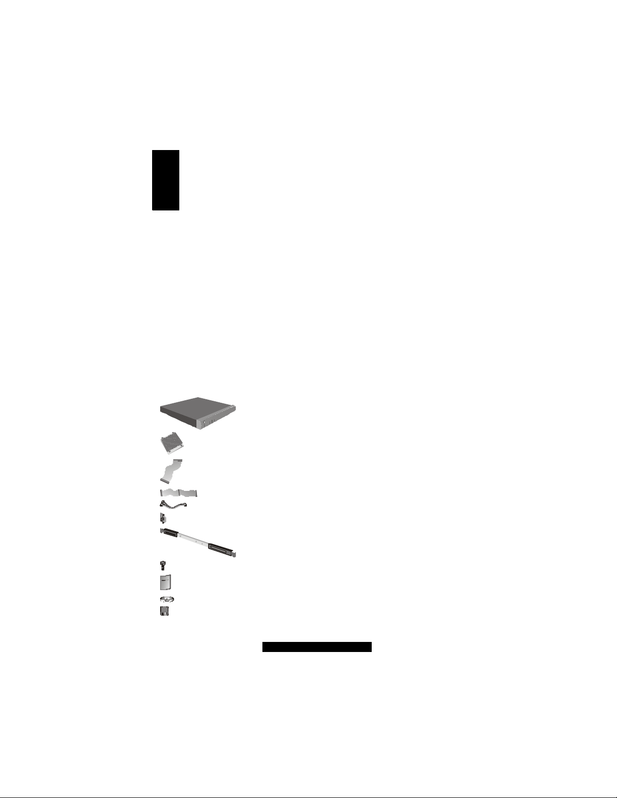
Unpacking
After unpacking the shipping carton, you should find these standard items:
1x Transport GS10 chassis
1x heatsink
2x two-headed IDE cable
1x three-headed IDE cable
1x three-headed power cable
1 pair mounting ears
Rack slides (option)
http://www.TYAN.com
Mounting screws
1x User’s Manual
1x driver CD
1x software driver flopp y disk for RAID
5
Page 6
Inspect all the items. If any item is damaged or missing, notify your dealer immediately.
Http Socket
Socket
Socket
Socket
Keep the shipping carton and packing materials in case you need to ship or store the computer in
the future.
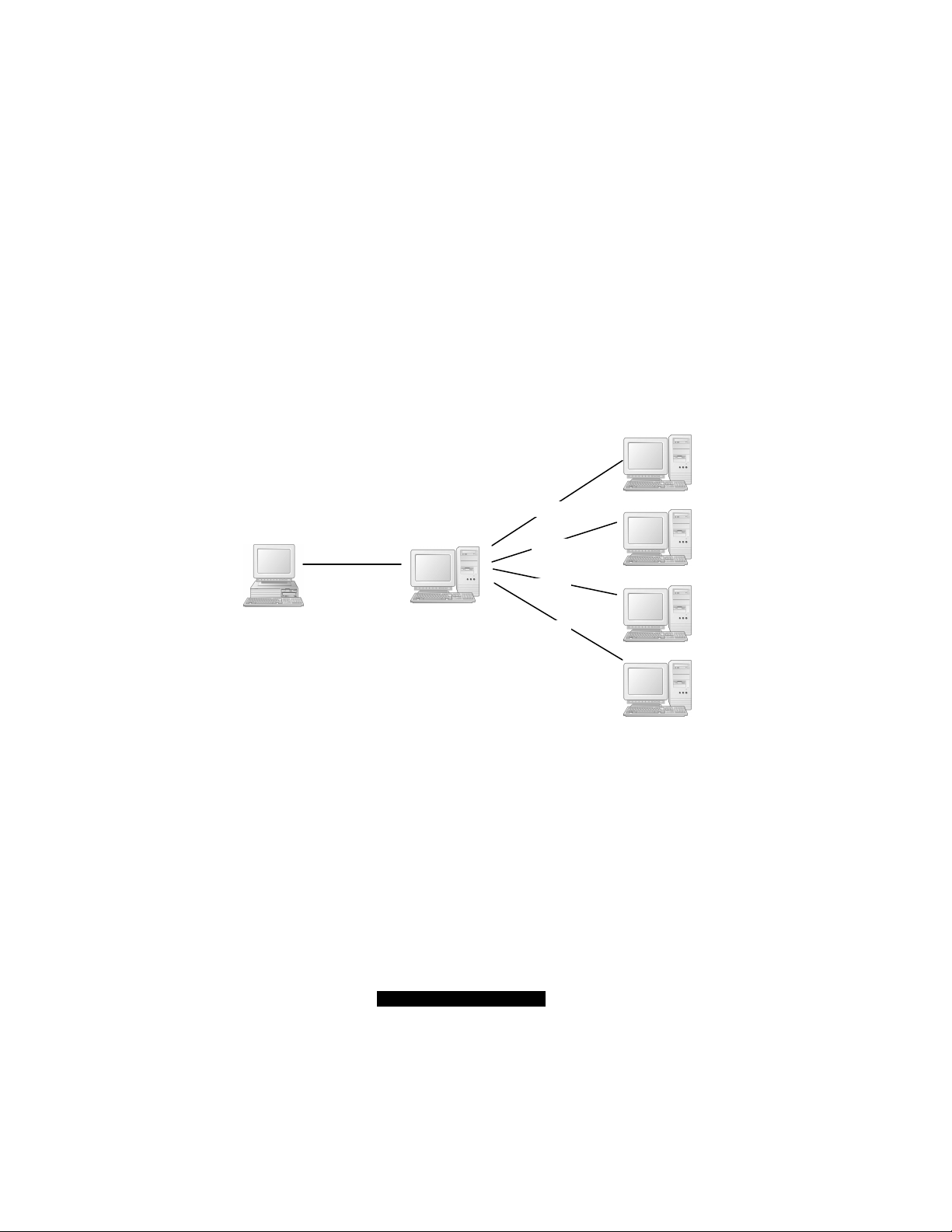
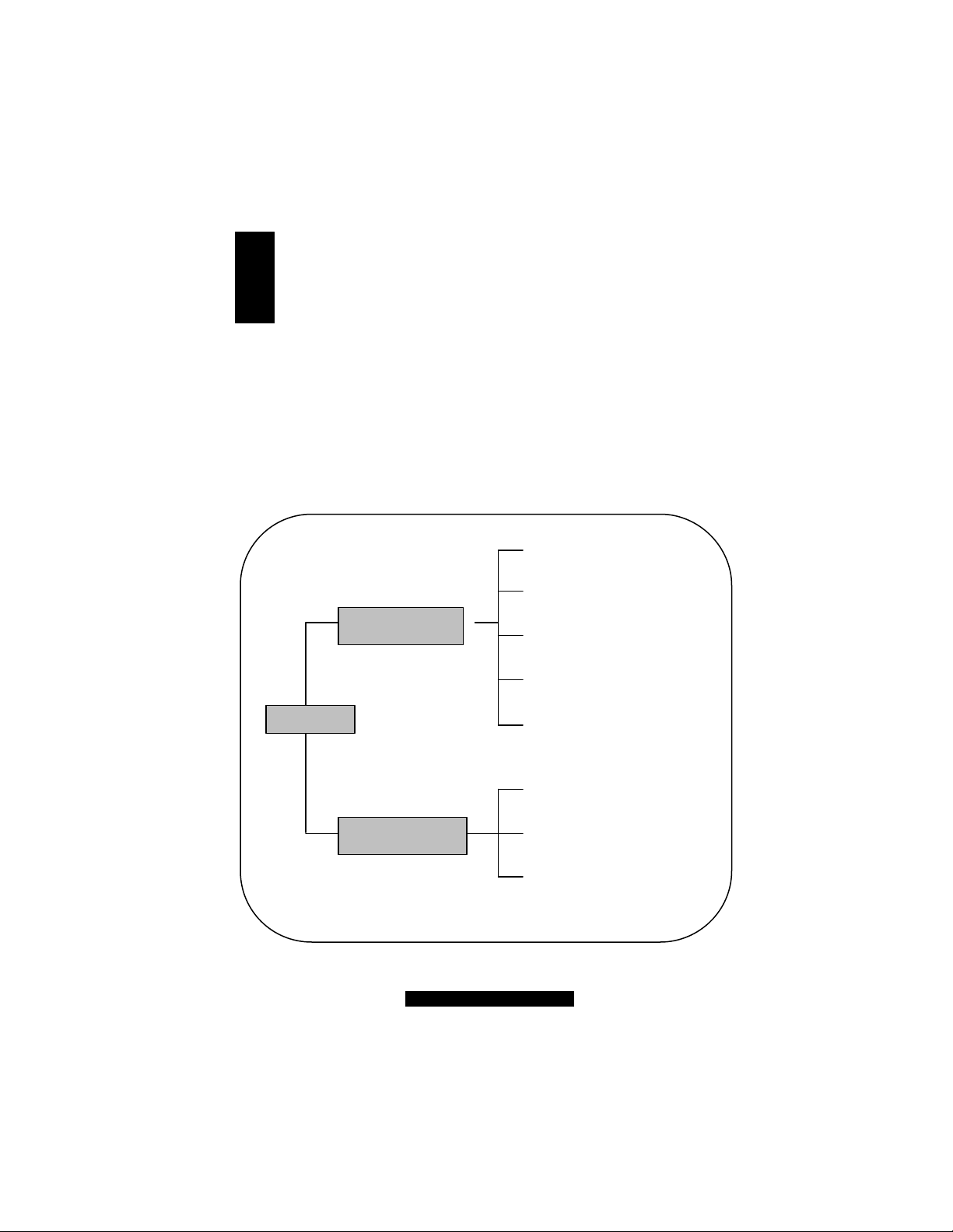
1.2 Product Description
Congratulations on purchasing the system. It is a server appliance providing a dedicated
web-hosting platform, pre-packaged in an industry standard 1U rackmount enclosure.
With appropriate application software, the system offers a full suite of Internet services including
web publishing, file transfer and email services. And through a browser, the administrator can
easily maintain the server through any client device.
Proxy Server
DNS Server
Browser
WWW Server
FTP Server
Mail Server
6
http://www.TYAN.com
Page 7

1.3 Specifications
NOTE: Specifications are subject to change without notice.
Processor
• Single socket 478
• Intel Pentium 4 processor up to 3.06 GHz
• Supports 400/533 MHz FSB
Chipset
• Intel 845E MCH
• MCH + ICH- 4
• NS PC87366 Super I/O chip
Memory
• Dual channel memory bus
• Two 184-pin DDR DIMM slots
• DDR 200 /266 support
• Up to 2 GB of unbuffered DDR
• Supports non -ECC/ECC type memory
modules
Expansion Slot
• 32-bit/33MHz PCI v2.2 slot
Integrated PCI Graphics
• ATI RageTM XL PCI graphics controller
• 8 MB frame buffer of video memory
External I/O Ports (Rear)
• One 9-pin UART serial port
• One VGA port
• Two RJ-45 LAN connectors
• Two USB 2.0 ports
Front Panel Features
• LED Indicator s
– Power
– LAN 1 and LAN 2 Link/Activity
– HDD
• LCD interface
– 2 x 16 digits
– Connected via COM2
– Four direction buttons plus one “Select”
and one “Cancel ” button
Networking
• Two 10/100Base -TX Ethernet LAN ports
(Intel 825 51QM controller)
• Supports TCP, UDP, IPv4 Checksum
off-load
Storage Interface
• Integrated two master IDE RAID controller
• Supports RAID level 0, 1
Storage Capacity
• Up to two IDE drives
Integrated Hardware Monitoring
• Integrated in Super I/O
• CPU temperature and v oltage monitoring
• CPU and system fan speed monitoring
• 3 x 3-Pin header for s ystem fans
BIOS
• Phoenix BIOS on 4 MB Flash (FWH)
• ACPI 1.0b / APM 1.2
• Detect function of H/W monitoring
• Auto configuration of IDE hard disk types
• Quick boot and multiple boot options
• LAN remote boot (PXE) support
• Power Management: S1 and S5 -type
Environment
• Operating temperature:
• Operating humidity:
Cabinet Form Factor
• Sub-1U rack- mountable chassis
• Dimension:
• Weight: 7 k g
Power Supply
• ATX12V 250W with PFC
Accessory
• One 32 -bit single PCI riser card
Regulatory
• FCC Class A (Declaration of Conformity)
• CE (Declaration of Conformity)
(Promise PDC20276)
and control
0 ? (32 ? ) to 40 ? (104 ? )
0 % to 80 % non -condensing
W16.7 x D15.3 x H1.7 inch
W424 x D387.7 x H43.5mm
http://www.TYAN.com
7
Page 8
1.4 System View
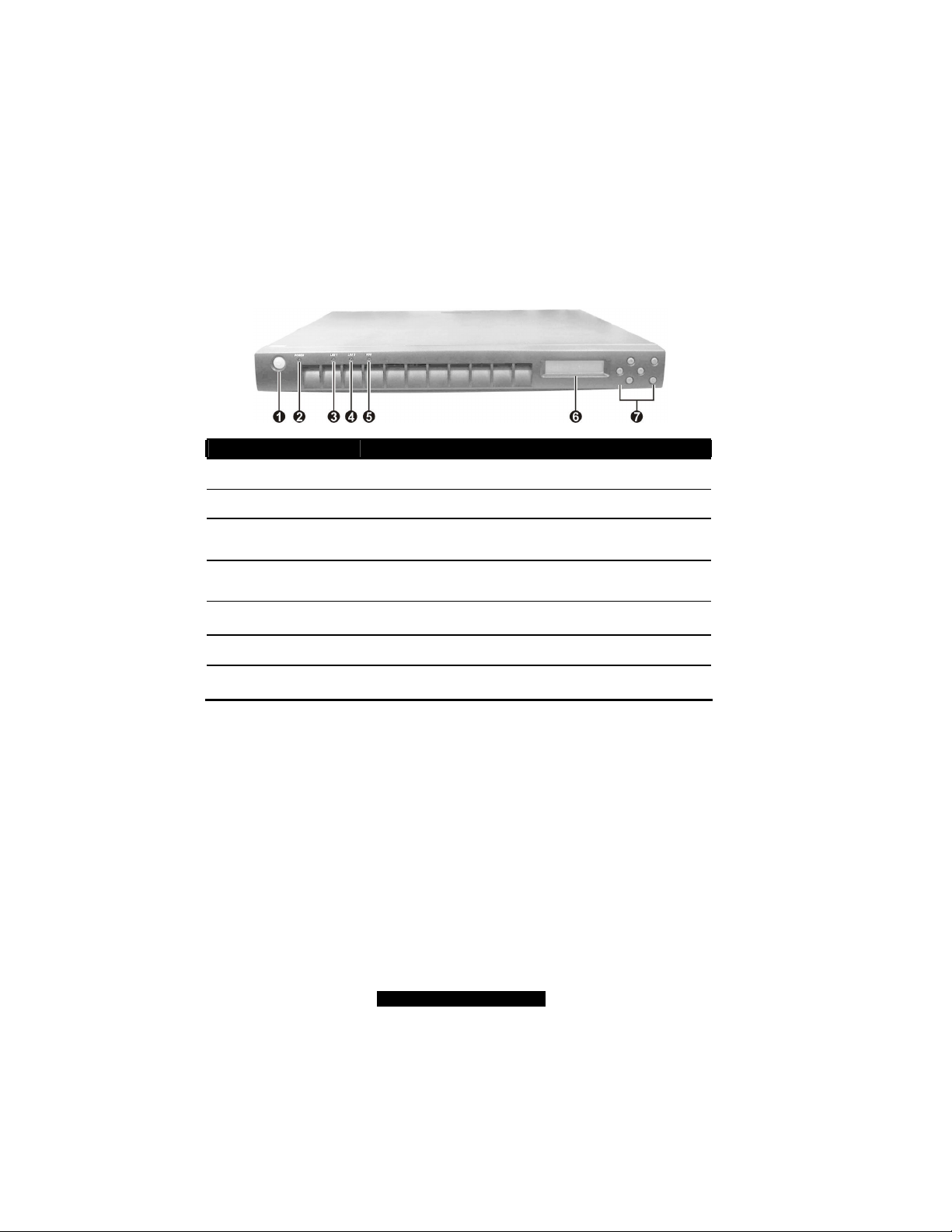
Front View
Ref
Œ
•
Ž
•
•
‘
’
Component Description
Power Button Turns the power on and off (soft-off).
Power Indicator Glows green when the power is on.
LAN1 Indicator Indicates an active network connection on LAN1 (external connection).
LAN2 Indicator Indicates an active network connection on LAN2 (internal connection).
Hard Disk Drive
Indicator
LCD Screen Displays messages and values entered.
Control Buttons Allow you to enter network configuration information, reboot the system,
Indicates activity on the hard disk drive.
and power down the system.
http://www.TYAN.com
8
Page 9
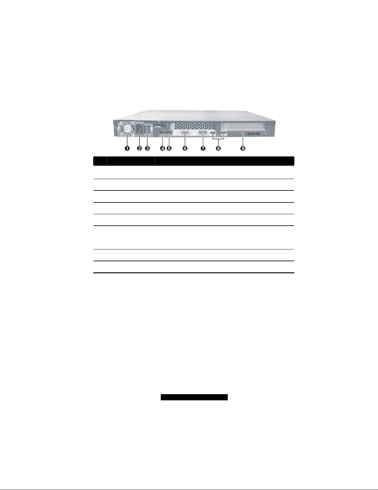
Rear View
Ref
Œ
•
Ž
•
•
‘
’
“
”
Component Description
Ventilation Openings Maintain proper operating temperature. Do not cover or block the
openings.
Power Connector Connects the power cord.
Power Switch Turns the main power of the system on and off.
LAN1 Connector Connects the LAN cable for internal network connection.
LAN2 Connector Connects the LAN cable for external network connection.
VGA Port Connects an external CRT monitor .
Serial Port Connects a serial device .
USB Ports Each of the two ports connects a USB device.
Expansion Slot Allow you to install a PCI card. (See page 17 for installation instructions.)
http://www.TYAN.com
9
Page 10

Page 11
2 Cabinet Installation
System Assembl
y Rack Mounting
Hard Disk Drive
Cabinet
Rails and Ears
Cabinet
into the Rack
Locking Tab
DIMM
Riser Card
Start
This chapter, which is divided into two sections, provides instructions on the hardware installation
of the system. System Assembly section illustrates how to assemble each component of the
system. Rack Mounting section describes the procedures for mounting the system into the rack.
You can use the system assembly flowchart and the chart next to determine the proper sequence
for removing or installing components to the server.
Cabinet Cover
CPU and Heatsink
11
http://www.TYAN.com
Page 12
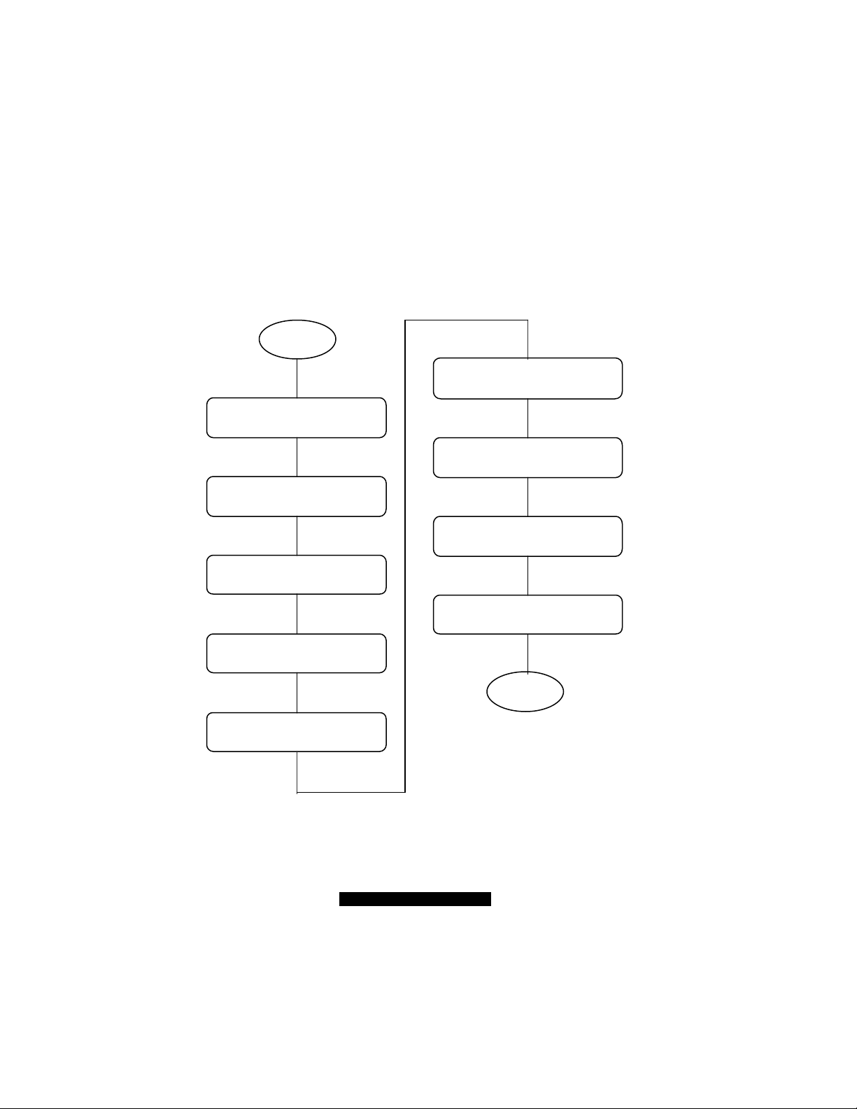
System Assembly Flowchart
FINISH
START
REMOVE CA
BINET
COVER
INSTALL
INSTALL
INSTALL
CONNECT H
ARD DISK
INSTALL
CHECK IF ALL PARTS
REPLACE
The following flowchart shows the basic procedures of system assembly:
NOTE: Please wear anti- static gloves when handling electrical components and exercise
caution during the installation process. For more information, contact your local dealer or
an experienced technician.
AND AIR DUCT
CPU AND HEATSINK
REPLACE AIR DUCT
DRIVE CABLE
AND POWER CORD
RISER CARD
ARE PROPERLY CONNECTED
CABINET COVER
SYSTEM MEMORY
HARD DISK DRIVE
12
http://www.TYAN.com
Page 13
2.1 System Assembly
When installing a device, be sure to read the instructions accompanying the device together with
the relevant section in this chapter.
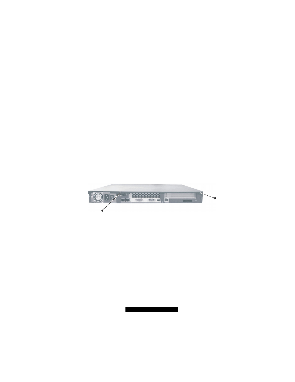
Opening the Cover
CAUTION:
l Static electricity can destroy electronic devices. Whenever you handle an option outside
of its protective packaging, first discharge any static electricity from your body by
touching a protective grounding device or unpainted metal on the rear panel of the
system before unplugging the power cord.
l Before you install any option, turn all power switches off. Unplug all power cords from
the system and all peripherals. Leaving the power on can cause serious damage to your
system.
l If the system is mounted on an equipment rack, remove the system from the rack and
take it to a service area. Do not attempt to disassemble the system while it is still in the
1. Remove two screws from the back of the system. Pull the cover backward to detach it.
2. To replace the cover, slide the cover forward and replace t he two screws.
equipment rack.
WARNING: Before you remove or install these modules, make sure that the system is not
turned on or connected to AC power.
Installing the CPU
Your system supports Socket 478 Intel Pentium 4 processor up to 3.06 GHz.
1. Remove the cabinet cover (see previous section).
2. Remove the air duct from the chassis by unfastening three side screws.
13
http://www.TYAN.com
Page 14
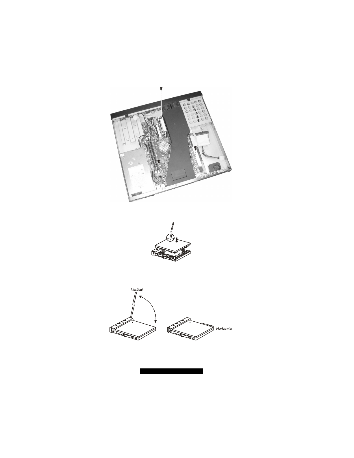
3. Locate the CPU socket and lift the socket arm up to the vertical position. Align the new CPU
so its Pin 1 corner (beveled corner) is at the Pin 1 corner of the socket.
4. Insert the CPU pins into the socket. Press the arm downward to the horizontal position. You
will feel some resistance while doing so. This is normal as the pressure starts to secure the
CPU in place.
14
http://www.TYAN.com
Page 15

5. Align the four points of the heatsink socket and secure with four screws following a diagonal
sequence.
6. Place the air duct back into place and secure with three screws.
7. Replace the cabinet cover.
Installing System Memory
Your system has two 184-pin DIMM (Dual In-line Memory Module) sockets to support a
maximum of 2 G B. You must follow these requirements for the DIMM to be used with the
system:
l Unbuffered DDR- SDRAM (Double Data Rate Synchronous DRAM) with ECC
l PC1600/PC2100-compliant
l 2.5 V
Follow this procedure to install a DIMM:
1. Open the cabinet cover (see previous section).
2. Locate the DIMM sockets.
15
http://www.TYAN.com
Page 16
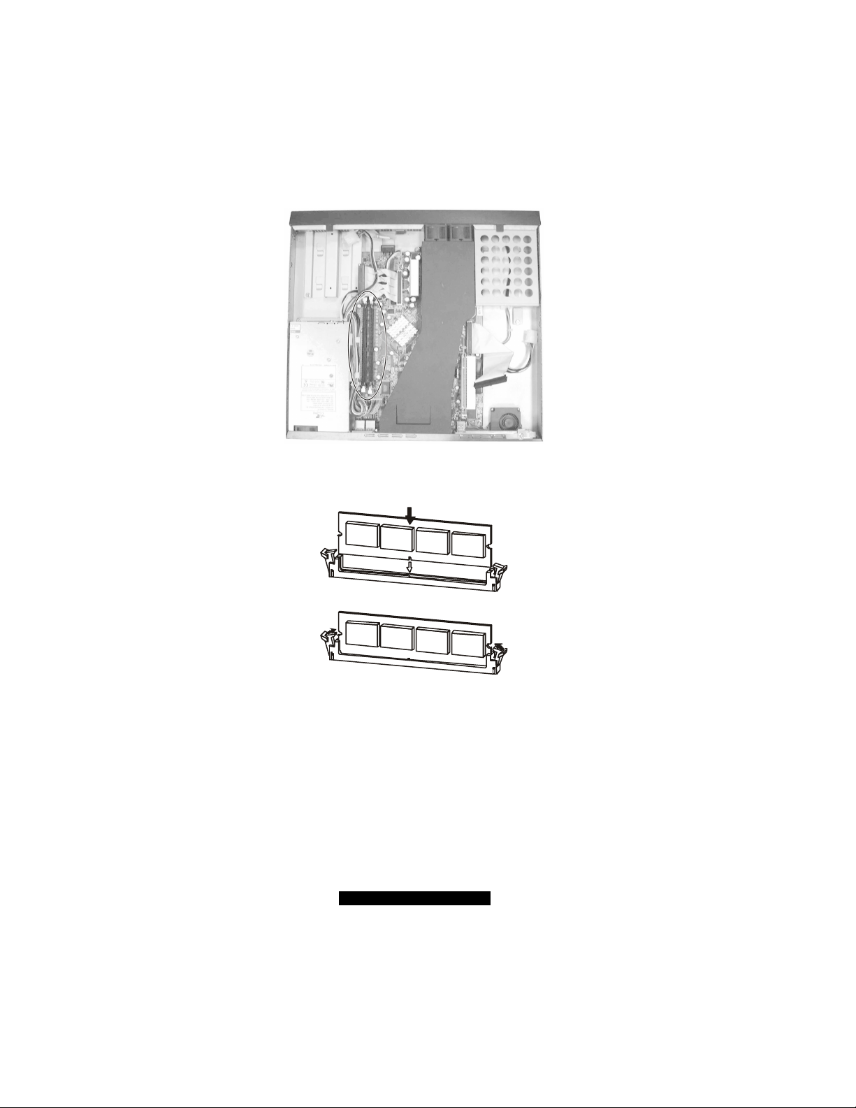
3. To install the DIMM, make sure the retaining clips are in the unlocked position, then align the
DIMM’s notched end with the socket’s corresponding end and firmly insert the DIMM into
the socket. Finally push the retaining clips inwards to lock the DIMM in place.
4. Replace the cabinet cover.
Installing a Hard Disk Drive
NOTE: Make sure that the jumper setting of the hard disk drive is set to “Master.” (See the
hard disk drive’s documentation for information.)
1. Remove the cabinet cover (see previous section).
2. Remove the screw from the hard disk drive bracket and detach the bracket from the cabinet.
16
http://www.TYAN.com
Page 17
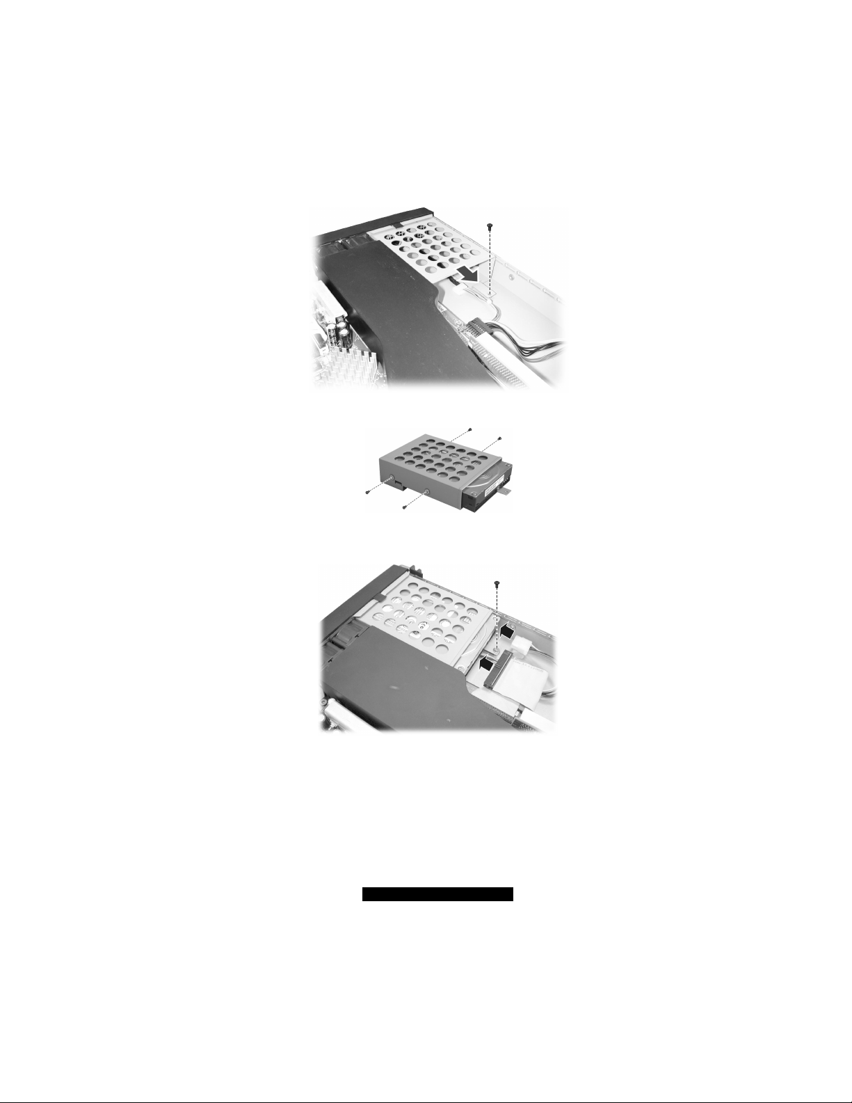
3. Fit a hard disk drive to the bracket and secure with four screws.
4. Fit the bracket with the hard disk driv e back into place and secure with one screw. Connect
the data cable and power cord.
5. Replace the cabinet cover.
6. You can create or rebuild RAID for the hard disk drive (see chapter 7 for information).
Installing a Riser Card
Your system has one PCI slot located on the system board. You need to install a riser card to be
able to install an expansion card for additional or enhanced functions.
1. Remove the cabinet cover (see previous section).
17
http://www.TYAN.com
Page 18

2. Locate the PCI slot.
3. Firmly press the riser card’s edge connector into the PCI slot.
4. Replace the cabinet cover.
2.2 Rack Mounting
T he slide rackmount kit provides a sliding rackmount solution for the product. Slides enable
optimal serviceability of the server from the front of the rack, including a ccessibility to the rear of
the server for cabling and the capability for top cover removal. It is compatible with most 19” EIA
standard 4 post racks with non-threaded holes.
After unpacking the shipping carton, you should find these standard items:
l 2 mounting ears
l 2 rack slides (inner and outer slides)
l 4 post slide mount adapters
l hex screws (+) and hex nuts (for outer slides)
l hex screws (for slide mount adapter – dark colored)
Inspect all the items. If any item is damaged or missing, notify your dealer immediately.
Cabinet Slides and Ears
1. Attach the mounting ears to the side near the front of the cabinet. Then secure each with two
screws.
18
http://www.TYAN.com
Page 19

2. Detach the inner slide from the outer slide by pressing on the release latch Πand pulling
apart the inner slide from the outer slide •. Do the same for the other slide.
3. Align the inner slide’s first round screwhole with the screwhole on the system chassis beside
the mounting ears and attach the screw together with next screwhole. Do the same for the
other side.
NOTE: For the correct orientation on mounting the inner slides to the cabinet, refer to the
picture above.
4. Attach a post slide mount adapter to the front end of the outer slide by securing 2 sets of hex
screws and hex nuts together without stretching the inner rails.
5. Attach a post slide mount adapter to the rear end by moving the inner rails to expose the
screw holes. Do the same for the other outer slide.
6. Attach the newly assembled outer slide with the post slide mount adapters to the front and
rear corner s of the rack that you will use to place the system chassis by securing only the first
and last screwholes (dark-colored screws), omitting the middle screwhole. Do the same for
the other side.
19
http://www.TYAN.com
Page 20

Cabinet into the Rack
Slide system cabinet Πwith the inner slides previously installed into the inner rails of the outer
slides attached to the rack and press on the release latch • until the front panel is aligned with the
front edge of the rack.
Locking Tab
To prevent the system chassis from sliding on its rails, secure the system cabinet to the rack with a
screw on each of the mounting ears Ž (optional – refer to the figure above).
20
http://www.TYAN.com
Page 21

3 Setting Up the System
This chapter tells you how to set up the system for use.
3.1 System Requirements
To use the system, you need :
l A 10Base-T, 10/100Base-TX, or 100Base-TX TCP/IP -based LAN
l A computer connected to the network that uses a Web browser (Netscape Navigator or
Microsoft Internet Explorer, version 4.0 or later)
l Network parameters including IP address for the system, the subnet mask of your network,
and a gateway/router address (if communicating with other networks)
l Third-party software applications (if not supplied or pre- installed)
3.2 Placing the System
You can either place the system on a flat surface – a desk or shelf, for example – or install it in a
standard 19 -inch equipment rack.
To place the system on a flat surface, attach the rubber feet to the corners in the bottom of the case.
If you will be using the system in an equipment rack, you need to purchase a slide rackmount kit.
(Please contact your dealer.)
CAUTION: Before installing the system in an equipment rack, make sure that:
l The ambient temperature around the system (which may be higher than the room
temperature) is within the limits specified in section 1.3.
l There is sufficient airflow around the unit.
l Electrical circuits are not overloaded.
21
http://www.TYAN.com
Page 22

l The equipment is properly grounded.
l Do not place any objects on top of the system.
3.3 Making the Connection
1. Connect one end of a Category 5 Ethernet cable to the LAN1 connector on the system and the
other end to the network socket that connects to the external network.
2. Connect one end of a Category 5 Ethernet cable to the LAN2 connector on the system and the
other end to the network socket that connects t o the clients.
3. Connect one end of the power cord to the system and the other end to an electrical outlet.
4. Switch on (I) the main power switch on the back of the system.
NOTE: After the power switch is switched on for the first time, it can remain in the ON
position. For later powering on and off, use the power button on the front of the system.
5. Press the power button to turn on the system. The hard disk drive spins up, the fan turns on,
and the LCD screen lights up. A number of status messages are displ ayed on the screen
during the boot process.
22
http://www.TYAN.com
Page 23

CAUTION: It is important to follow the proper power-down procedure for turning off the
system. See section 3.6 in this chapter.
3.4 Configuring the System
After you have made the network and power connections, you can configure the network settings
using the LCD console.
Before You Begin
NOTE: To take advantage of the LCD console feature, make sure that the LCD driver is
correctly installed (see chapter 5).
Before you begin, make sure that you have the following information ready:
l IP address assigned to the system
l Subnet mask of your network
l Gateway/router address (necessary only if communicating with other networks)
Using the LCD Console
The LCD screen on the front of the system displays two lines of text. The first line shows the
information required; the second line shows the data already entered. You can enter the data by
using the arrow buttons to the right of the LCD screen.
The Left arrow button moves the cursor to the left.
The Right arrow button moves the cursor to the right.
The Up arrow button increases the digit located at the cursor position.
The Down arrow button decreases the digit located at the cursor position.
The S (Select) button accepts the data entered or selects the option displayed.
The C (Cancel) cancels the data entered or the option displayed.
23
http://www.TYAN.com
Page 24

Setting the Configuration
For Linux
1. Press the button according to the number of times specified on the following table, and
you will see the corresponding prompt.
KEY PRESS PROMPT FUNCTION
once (1)
twice (2)
thrice (3)
four (4) times
five (5) times
six (6) times
seven (7) times
eight (8) times
nine (9) times
NIC1 IPADDR
Change?
NIC1 NETMASK
Change?
NIC2 IPADDR
Change ?
NIC2 NETMASK
Change ?
Default GW
Change ?
Primary DNS
Change ?
Secondary DNS
Change ?
Reboot
Server ?
Shutdown
Server ?
E nter the IP address assigned to NIC 1 (Network
Interface Card)
E nter the netmask of NIC 1
E nter the IP address assigned to NIC 2
E nter the netmask of NIC 2
E nter IP address of the gateway for your network
E nter IP address of the primary DNS for your network
E nter IP address of the secondary DNS for your
network
Allows you to reboot the server
Allows you to shutdown the server
2. Press the button to confirm selection of the option displayed.
3. Use the button to increase or button to decrease the value.
4. Then, press the button to accept the data entered and return to the main screen.
NOTE: Please restart the LCD driver under Linux when you change the NIC settings from
Static to DHCP by running “killall LCDdaemon”, and then running
/LCD/LCDdaemon.
24
http://www.TYAN.com
Page 25

For Windows
1. Press the button according to the number of times specified on the following table, and
you will see the corresponding prompt.
KEY PRE SS PROMPT FUNCTION
once (1)
twice (2)
thrice (3)
four (4) times
five (5) times
six (6) times
seven (7) times
eight (8) times
nine (9) times
ten (10) times
eleven (11) times
twelve (12) times
NIC1 IPADDR
Change?
NIC1 NETMASK
Change?
NIC1 GATEWAY
Change?
NIC1 DNS1
Change?
NIC1 DNS2
Change?
Reboot
Server?
Shutdown
Server?
NIC2 IPADDR
Change?
NIC2 NETMASK
Change?
NIC2 GATEWAY
Change?
NIC2 DNS1
Change?
NIC2 DNS2
Change?
E nter the IP address assigned to NIC1
E nter the netmask of your network to NIC1
E nter IP address of the gateway for your network
E nter the primary DNS address assigned to the
NIC1
E nter the secondary DNS address assigned to the
NIC1
Allows you to reboot the server
Allows you to shutdown the server
E nter IP address assigned to the NIC2
E nter netmask address assigned to the NIC2
E nter gateway address assigned to the NIC2
E nter primary DNS address assigned to the NIC2
E nter secondary DNS address assigned to the NIC2
2. Press the button to confirm selection of the option displayed.
3. Use the button to increase or button to decrease the value .
4. Then, press the button to accept the data entered and return to the main screen.
NOTE: If you press the button to cancel the configuration, you must go through the
entry process again.
25
http://www.TYAN.com
Page 26

Setting Up With the Web Browser
The remainder of the setup process is performed through a Web browser (Netscape Navigator or
Microsoft Internet Explorer, version 4.0 or later) on any client computer connected to the server.
Depending on your model, all the software may have been pre-installed by the manufacturer or
dealer. See the software manual for setup instructions.
3.5 Rebooting the System
Follow this procedure to reboot the system:
For Linux
Press the button eight times or pre ss two times , and you will see the prompt:
Reboot server?
Press the button.
For Windows
Press the button six times, and you will see the prompt: Reboot server?
Press the button.
3.6 Powering Down the System
CAUTION: To prevent possible loss of data, it is important to follow the proper
power-down procedure for turning off the system.
Follow this procedure to power down the system:
For Linux
Press the button nine times or press , and you will see the prompt: Shut down
server?
Press the button and when the power is off, the power indicator turns off.
26
http://www.TYAN.com
Page 27

For Windows
Press the button seven times , and you will see the prompt: Shut down server?
Press the button and when the power is off, the power indicator turns off.
3.7 Linux RedHat Installation Notes
Due to the compatibility limitation between Linux RedHat 7.3 (and up) and some types of HDD,
the following warning message may appear during Linux installation:
The kernel was unable to re-read the partition table on /dev/hd*
Device or resource busy, this means Linux knows nothing about any modifications you made.
You should reboot your computer before doing anything with /dev/hd* (hd* refers to the
HDD’s method of connection, e.g., the master device of IDE0 is /dev/had while the master
device of IDE1 is /dev/hdc).
In this case, you can select the “Ignore” key until the warning message window is closed. T hen
you may encounter two different possibilities depending on whether the Linux partition on the
HDD was implemented the first time or not.
l First possibility:
When the HDD has RedHat 7.3 (and up) present in the Linux partition (and the current
installation is only for modifying, deleting, or adding a Linux partition), then the
installation program will continue with the rest of the process.
l Second possibility:
When the HDD does not have RedHat 7.3 (and up) present in the Linux partition (even if
there is any other type of partition existing, e.g. , NTFS), the installation program may show
this message –
An error occurred trying to initializ e swap on device hdc3, this
problem is serious and the installation cannot continue, Press
Enter to reboot your system
to suggest that you reboot your system. Then you can re- install RedHat 7.3 (and up) to solve
this issue (you may encounter the warning me ssage on the first possibility, just ignore it).
NOTES:
l The above possibilities may occur when you use a type of HDD which is not compatible
with Linux O/S. If you use the latest version (e.g., Linux RedHat 9.0 or the new
Seagate Alpine series HDD), then the above possibilities may not occur.
l The above possibilities will not affect system performance.
27
http://www.TYAN.com
Page 28

Page 29

4 Configuring the System
4.1 BIOS Setup Program
BIOS Setup (SCU or Setup Configuration Utility) is a program for configuring the BIOS (Basic
Input/Output System) settings of the system.
You need to run the BIOS Setup program when:
l You see an error message on the screen requesting you to run Setup.
l You want to restore the factory default settings.
l You want to modify some specific settings according to the hardware.
l You want to modify some specific settings to optimize system performance.
Starting BIOS Setup
NOTES:
l The Setup screens shown in this chapter are for your reference only. The actual items
or settings on your computer may differ.
l The Setup program may hav e been updated after the publication of this manual.
l The settings you select in your operating system might override similar settings in
To run BIOS Setup, press Del when the prompt appears in the screen during system startup. The
prompt shows up on the screen for only a few seconds. You must press Del quickly.
Use the keyboard to move around and make selections. Keyboard information can be found at the
bottom of the screen. A brief description of keyboard usage is listed next:
Setup.
Key Function
F1
←, →
↑, ↓
+, − Scrolls forward or backward among the values for the highlighted field.
Enter
Esc
Displays help information.
Selects a menu title.
Moves the highlight up or down among fields.
Pops up an option window for the highlighted field.
1) Returns to the main menu from a sub-menu.
29
http://www.TYAN.com
Page 30

2) Exits Setup.
F9 Restores the Setup defaults.
F10
Saves changes and exits Setup.
Main Menu
The Main menu contains the basic configuration settings of your system.
System Time sets the system time (Hour, Minute, Second).
System Date sets the system date (Day, Month, Year).
Primary/Secondary Master/Slave Each of these four items sets the type of the IDE device in
your system.
NOTE: Your computer cabinet can accommodate up to two IDE devices only although the
BIOS supports up to four devices.
Boot Features
Summary Screen enables or disables the displaying onscreen of various system information
while booting.
QuickBoot Mode sets if the system will skip certain tests while booting. This will decrease
the time needed to boot the system.
System Memory Shows the total memory on your system.
Extended Memory Shows the total extended memory on your system.
Advanced Menu
The Advanced menu contains the input/output configuration settings of the system.
Installed O/S sets the operating system to be installed.
Reset Configuration Data Normally, you would leave this field disabled. Select Yes to reset the
Extended System Configuration Data (ESCD) when you exit Setup if you have installed a new
add-on de vice and the system reconfiguration has caused such a serious conflict of resources that
the operating system cannot boot.
Large Disk Access Mode Select DOS or Other.
Local Bus IDE Adapter enables or disables the integrated local bus IDE adapter.
Legacy USB Support enables or disables support for Legacy Universal Serial Bus in
non-USB -aware operating systems like DOS.
Spread Spectrum enables or disables the Spread Spectrum function to reduce the EMI
(Electro-Magnetic Interference) effect.
30
http://www.TYAN.com
Page 31

Advanced Chipset Control
Graphics Aperture sets the memory size of AGP VGA device.
Enable Memory Gap enables or disables memory gap.
USB 2.0 Controller enables or disables USB 2.0 controller.
ECC Config allows you to enable or disable support for ECC-type of memory. Available
only if you are using an ECC-type DDR- SDRAM memory.
ECC Error Type generates interrupt when an ECC error occurs. Available only if you are
using an ECC-type DDR-SDRAM memory.
SERR Signal Condition selects ECC error condition that SERR# be asserted.
Frequency Ratio Only available if you are using an unlocked processor. If the processor’s
frequency multiple is locked, you will not see this item.
Advanced Processor Options
APIC Interrupt Routing turns on and initializes I/O APIC (Advanced Programmable
Interrupt Controller).
Compatible FPU Code enables or disables FPU (Floating Point Unit).
I/O Device Configuration
Serial Port A/B, Base I/O Address, and Interrupt Sets the input/output address and
interrupt request line (IRQ) for the on-board serial ports (COMA/COMB) controller.
Fan Speed Control enables or disables fan speed control.
Hardware Monitor Configuration The following items on your system are monitored:
l VDDQ (voltage)
l Vcc 2.5 (voltage)
l Vcc (voltage)
l +5 Vsb (voltage)
l Vcc 3 (voltage)
l Vcc P (voltage)
l CPU Temperature
l System Temperature
l FAN1 (speed)
l FAN2 (speed)
l FAN3 (speed)
Onboard Device Configuration
Onboard ATI RAGE XL enables or disables onboard ATI VGA controller.
Onboard Intel NIC1/NIC2 enables or disables onboard Intel 82551QM LAN1/LAN2
controller.
Onboard Promise RAID enables or disables onboard Promise PDC20276 controller.
Console Redirection The Console Redirection is a feature for monitoring POST messages and
running Setup and DOS from a remote serial terminal.
31
http://www.TYAN.com
Page 32

COM Port Address if enabled, will use a port on the system board.
Baud Rate enables the specified baud rate.
Console Type enables the specified console type.
Flow Control enables Flow Control.
Console Connection indicates whether the console is connected directly to the system or
uses a modem to connect.
Continue C.R. After POST enables Console Redirection after operating system has loaded.
Security Menu
The Security menu contains the security settings that protect your system against unauthorized
use.
Supervisor/User Password indicates if a Supervisor or User password exists.
Set Supervisor/User Password sets the Supervisor/User password. The Supervisor can access
the Setup program and boot the system while the User can only boot the system. Passwords are
not cas e sensitive.
Diskette Access sets the accessibility of the floppy disk drive.
Fixed Disk Boot Sector protect the boot sector against any changed.
CAUTION: Set this item to disabled before installing an operating system, running
Fdisk or Format program, or when re-installing software. Otherwise, the intended
action will fail.
Virus Check Reminder displays the virus check reminder message during system boot up.
System Backup Reminder displays the system back up reminder message during system boot
up.
Password on Boot determines if the system will request a password when starting up.
Power Menu
The Power menu contains the power management settings that help save system power.
Enable ACPI enables or disables ACPI (Advanced Configuration Power Interface) – a power
management standard used by the operating system.
Power Saving sets the power saving mode.
Standby Timeout sets the timer for the system to enter Standby mode when it has been idle for
the set time period.
Resume On Modem Ring sets if the system will wake up from Standby mode when an incoming
call occurs.
Resume On Time/Resume Time allows the system to wake up at a specific time.
32
http://www.TYAN.com
Page 33

Wake On LAN allows the system to wake up upon detection of any activity on the LAN.
Power Button Behavior sets the desired system power state when the power button is pressed.
Suspend Mode selects the type of Suspend mode.
After Power Failure sets the mode of operation if there has been an AC power loss. Power Off
causes the system to remain off when power is restored. Power On causes the system to start up
when power is restored. Last State causes the system to return to the state it was before power loss.
Boot Menu
The Boot menu allows you to set the priority of the booting devices. There are six possible
devices:
l Removable Devices
l Hard Drive
l CD-ROM
l IBA 4.1.06 Slot 0230 (LAN Intel 82551QM#1)
l IBA 4.1.06 Slot 0238 (LAN Intel 82551QM#2)
Use the up or down arrow key to select a device and press the plus (+) key to move the device
upward or minus ( −) key to move it downward.
Exit Menu
The Exit menu contains the ways of exiting the Setup program.
Exit Saving Change saves the changes you have made and exits the Setup program.
Exit Discarding Change exits the Setup program without saving any changes.
Load Setup Defaults loads the default values for all Setup items.
Discard Changes loads previous values for all Setup items.
Save Changes saves the changes you have made.
33
http://www.TYAN.com
Page 34

4.2 Jumper Settings
Jumpers provide a way to reconfigure the circuitry on the system board for specific needs. When
you change the CPU or want to reset the BIOS configuration, you need to change the jumper
settings.
See the next figure for jumper locations and the table that follow for jumper definitions.
CAUTION: Jumpers not described in this section are reserv ed for factory use only. Do not
change the default settings.
Jumper Definition Setting Description
1- 2 Normal (default) CCMOS1 CMOS setting
JP1 CPU bus
frequency
setting
2- 3 Clear CMOS
1- 2 Auto-detect (default)
2- 3 100 MHz
None 133 MHz
To clear the RTC and CMOS RAM, set CCMOS1 to
2 -3 for one second and set it back to 1-2 again.
34
http://www.TYAN.com
Page 35

5 Installing Software Drivers
You need to install the software drivers using the CD supplied with your system. The drivers are
required for taking full advantage of its unique features.
NOTE: The driver CD may have been updated after this User’s Manual was completed. If
your CD is different from that described in this chapter, refer to the README files on the
CD. These files contain the latest information from the software supplier.
5.1 Installation Instructions for Windows
An autorun program is provided on the driver CD to help you easily install the drivers. As you
insert the CD, the autorun program automatically starts. If you need to start the program manually,
run t he TYANCD.exe program of the CD.
The main screen appears as shown next:
35
http://www.TYAN.com
Page 36

5.2 Installation Instructions for Linux RedHat
LCD Driver
The LCD driver is required to enable your system to use the LCD panel to set the network, restart
and shutdown the server. To install this driver, follow these steps:
1. Insert the driver CD into the CD drive.
2. Browse to the following directory: /mnt/cdrom/ and create the following directory:
/tempLCD.
3. Unzip the LCDxx.tar.gz file located in the /mnt/cdrom/ directory into the
/tempLCD directory. After unzipping, the following files should appear:
LCDdaemon
LCDInstall
readme.txt
4. Run LCDInstall (./LCDInstall).
5. Enable the LCD controller:
36
http://www.TYAN.com
Page 37

cd /LCD
./LCDdaemon.
6. To enable the LCD controller after system boot up, add the following into the file
/etc/rd.local.
cd /LCD
./LCDdaemon
RAID (Redundant Arrays of Inexpensive Disks) Driver
The RAID driver is required to enable your system to use RAID IDE devices. To install this
driver, follow these steps:
The files are located on the following locations:
l Driver CD \Promise\20276\Linux directory
l Driver floppy disk for RAID
1. Extract the contents of the ZIP file on to a formatted floppy disk. (ZIP file can be extracted by
using WinZIP in Windows or Unzip in Linux).
2. Label this floppy disk as “FastTrak Driver Disk.”
Installing the driver into an existing system –
1. Boot the Linux system and login as root .
2. Insert the FastTrak driver disk into the USB floppy drive and issue the following commands:
# mount /dev/sdb /mnt/floppy
# cd /mnt/floppy
# sh install
Answer Yes/No when you are asked to perform the setup configuration.
Upon selecting Yes to bind the driver into the Linux system boot up, issue the following
commands:
# cd ..
# umount /dev/sdb
NOTE: All IDE channels except the first and second ones are disabled for the "Linux 2.4
IDE issue." It can be enabled by removing “ide2=0 ide3=0 ide4=0 ide5=0 ide6=0 ide7=0
ide8=0 ide9=0” in /etc/lilo.conf or /boot/grub/grub.conf.
3. Reboot the Linux RedHat system.
Installing the driver into a new system –
1. Start the RedHat Linux installation using a CD boot up .
37
http://www.TYAN.com
Page 38

2. At the "Welcome to RedHat Linux ..." installation screen, a prompt labeled "boot:" will
appear at the bottom of the screen.
3. Press TAB and append the parameters at the "boot:" prompt, then press Enter.
NOTE: Linux Kernel 2. 4.x will wrongly identify the Promise ATA RAID controller as an IDE
controller. This would result in the built-in Linux IDE driver trying to handle the controller
and can prevent the proper FastTrak ATA RAID driver from being loaded. Follow the
installation instructions and the parameter commands referred next. This is known as an
"IDE issue."
“Linux ide0=0x1f0,0x3f6,14 ide1=0x170,0x376,15 ide2=0 ide3=0
ide4=0 ide5=0 ide6=0 ide7=0 ide8=0 ide9=0 expert”
4. At the "Devices" window, insert the FastTrak driver disk in the floppy drive and then select
"OK" or "Yes" to continue the installation.
5. Enable the "Configure advanced boot loader options" option at the Boot Loader
Configuration menu, and type the following kernel parameters in the general kernel
parameters field.
"ide0=0x1f0,0x3f6,14 ide1=0x170,0x376,15 ide2=0 ide3=0 ide4=0
ide5=0 ide6=0 ide7=0 ide8=0 ide9=0”
6. Follow the onscreen instructions to continue.
7. When the warning message "The kernel was unable to re -read the
partition table on /dev/sd(x), (Device or resource busy)...", do
not click “Skip,” just click “Ignore” to continue the installation.
8. Press Ctrl+Alt+F2 when the "Congratulations" window appears.
9. Insert the FastTrak driver disk and type the following commands to load FastTrak driver:
# umount /tmp/s db (for safety issue, just in case)
# chroot /mnt/sysimage
When using the USB floppy drive, choose the USB floppy device such as /dev/sdb.
# mount /dev/sdb /mnt
# cd /mnt
# sh setup-ft
10. Choose your desired selection, after the FastTrak driver installation has been completed.
# cd /
# umount /mnt
# exit
11. Press Ctrl+Alt+F7 and click "Exit" to exit the installation.
NOTE for Linux RedHat 8.0: After you have installed the RAID driver, and If the USB
floppy drive is not shown, obtain the USB device driver file fir st, then perform the following:
38
http://www.TYAN.com
Page 39

1. Click the Gnome menu then click System Tools.
2. Select the Hardware Browser window and click Floppy Disks.
3. Obtain the USB floppy drive’s device file “ /dev/sdX” where X can be a .. z.
4. Activate the floppy drive by using the device file /dev/sdX.
39
http://www.TYAN.com
Page 40

Page 41

6 Expanding the System
You can expand the capabilities of the system by adding or upgrading internal devices. When
installing a device, be sure to read the instructions accompanying the device together with the
relevant section in this chapter.
6.1 Opening the Cover
CAUTION:
l Static electricity can destroy electronic devices. Whenever you handle an option
outside of its protective packaging, first discharge any static electricity from your body
by touching a protective grounding device or un painted metal on the rear panel of the
system before unplugging the power cord.
l Before you install any option, turn all power switches off. Unplug all power cords from
the system and all peripherals. Leaving the power on can cause serious damage to
your sy stem.
l If the system is mounted on an equipment rack, remove the system from the rack and
take it to a service area. Do not attempt to disassemble the system while it is still in the
1. Turn off the power of the system.
2. Disconnect all power cords and cables from the system.
3. Remove two screws from the back of the system. Pull the cover backward to detach it .
equipment rack.
41
http://www.TYAN.com
Page 42

6.2 Installing an Expansion Card
Retainer
Your system supports one PCI slot located on a riser card. You can install a PCI expansion card
for additional or enhanced functions. Follow this procedure to install an expansion card:
1. Before you purchase a PCI expansion card to add to the system, make sure that the card is
less than 7 inches (177.8 mm) long. Otherwise, it will not fit into the place.
2. Open the cabinet cover (see section 6.1 in this chapter).
3. Remove the screw, lift the small retainer, and then the metal slot cover. Keep the cover for
future use when you remove the card.
4. Firmly press the expansion card’s edge connector into the expansion slot and secure the
retainer with the screw.
5. Replace the cabinet cover.
42
http://www.TYAN.com
Page 43

NOTE: According to the standard X86 structure, there is only 128 k (C0000h-DFFFFh)
shadow RAM for system option ROM. For this system, the RAID card option ROM
engrosses 64 k, the onboard ATI VGA card engross es 32 k, the onboard LAN engrosses
more than 10 k, so the remain ing space for option ROM is very limited. You may encounter
the possibility that some PCI cards (e.g., SCSI PCI card) cannot be initialized and used
when the PCI card needs more shadow RAM for its option ROM. When you encounter this
possibility, please close the onboard device you are not presently us ing temporarily
(disable the options under the Onboard Device Configuration sub- items on the BIOS
Setup’s Advanced menu (refer to Chapter 4 Advanced Menu).
6.3 Adding a Secondary Hard Disk Drive
You can add a second hard disk drive. It is advised that you select a hard disk drive that meets the
following specifications. A hard disk drive that does not meet these specifications can cause
reliability problems in your system.
l Peak current draw: must not exceed 1.8 amperes maximum (at 5 volts) and 0.7 amperes
maximum (at 12 volts)
l Rotational speed: 5400/7200 rpm
l Interface: Ultra ATA66/100 (ATA133 for models supporting RAID)
l Operating temperature: must be able to operate in environments up to 55 °C
l Operating humidity: 10% to 90% (non-condensing)
l IDE and RAID IDE cannot be used at the same time
If you want to add a second hard disk drive, follow this procedure.
NOTE: Make sure that the jumper of the second hard disk drive is set to “Master.” (See the
hard disk drive’s document for information.)
1. Remove the cabinet cover (see section 6 .1 in this chapter).
2. Locate the bracket for the secondary hard disk drive, next to the power supply. Remove the
screw and slide the bracket off the metal tabs to detach it.
43
http://www.TYAN.com
Page 44

Secondary IDE Connector
3. Secure the hard disk drive to the bracket with four bottom screws.
4. Fit the bracket with the hard disk drive back into place and secure with one screw.
5. Connect one end of the data cable to the secondary IDE connector (see figure above) and the
other end to the rear of the hard disk drive.
NOTE: Connect the data cable to the secondary RAID IDE connector if using RAID disk
drive.
6. Connect the power cord to the rear of the hard disk drive.
7. You can create RAID for the hard disk drives (see Chapter 7 for information).
44
http://www.TYAN.com
Page 45

6.4 Adding a CD Drive (for test purpose)
Three-headed power
In case you need to use a CD drive with your system, follow this procedure.
WARNING: You are advised not to make frequent connection and disconnection on the
IDE connector as this might cause damage to the data cable and connector pins.
CAUTION: Follow the instructions in this section carefully. The DVD or CD drive contains a
laser device. D o not attempt to open the DVD or CD drive’s enclosure or remove a DVD or
CD drive using any procedures other than those contained in this section to avoid the risk of
exposure to harmful radiation.
With a Secondary Hard Disk Drive Installed
1. Remove the cabinet cover (see section 6.1).
2. Unplug the data cable and power cord from the rear of the secondary hard disk drive. Unplug
the other end of the data cable from the secondary IDE connector on the system board.
3. Use the three -headed power cable that came with your system and connect the single end to
the previously unplugged power cord (Œ) from step 2. Connect the remaining two ends of the
power cable, one to the rear of the secondary hard disk drive (•) and the other to the rear of
the CD drive (Ž).
cable
4. Use the three -headed data cable that came with your system and connect the single end to the
secondary IDE connector (Œ). Connect the remaining two ends of the data cable, one to the
rear of the secondary hard disk drive (•) and the other end to the rear of the CD drive (Ž).
45
http://www.TYAN.com
Page 46

Three-headed data cable
NOTE: You cannot replace the cabinet cover with a CD drive installed. Restore the old
connections after using the CD drive to be able to replace the cabinet cover.
Without a Secondary Hard Disk Drive Installed
1. Remove the cabinet cover (see section 6.1 in this chapter).
2. Connect one end of the data cable to the secondary IDE connector (see figure on page 44) and
the other end to the rear of the CD drive.
3. Connect the power cord to the rear of the CD drive.
NOTE: You cannot replace the cabinet cover with a CD drive installed. Remove the CD
drive after using it to be able to replace the cabinet cover.
46
http://www.TYAN.com
Page 47

7 Using RAID
7.1 About RAID
Depending on the model, your syst em may support RAID (Redundant Array of Inexpensive
Disk). The purpose of RAID is to combine multiple small, inexpensive disk drives into an array of
disk drives that appears to the system as a single logical storage device and yields performance
exceeding that of a Single Large Expensive Drive (SLED).
Your system provides a FastBuild Utility for creating your array. There are two types of array
architectures that you can create:
l RAID 0
In this type, data is split across drives, resulting in higher data thr oughput. Performance is
good but the failure of any disk in the array results in data loss. This type is commonly
referred to as striping.
l RAID 1 (Recommended)
In this type, data are written to two drives. If either drive fails, no data is lost. This type is
commonly referred to as mirroring.
NOTE: Use the command ‘expert’ to start Linux installation during ‘boot:’ when
prompted, if you want to use the RAID function on your system. Insert the RAID driver
diskette for Linux when prompted into the USB floppy drive, and follow the onscreen
instructions to complete the installation process.
CAUTION:
l You must use an 80-wire, 40-pin cable when connecting an Ultra ATA/133 hard drive to
the system board.
l If creating a Security array using an existing hard drive, back up any necessary data.
Failure to follow this could result in data loss.
47
http://www.TYAN.com
Page 48

7.2 Creating an Array
1. Boot your system and when the following messages display on the screen, press Ctrl+F to run
FastBuild Utility.
MBFastTrak133 Lite ™ BIOS Version 2.00.0.XX
© 19 95-2000 Promise Technology, Inc. All Rights Reserved.
No array defined...
Press <Ctrl -F> to enter FastBuild ™ Utility
Or press <ESC> key to continue booting the system.
2. The FastBuild Utility main menu appears on the screen.
FastBuild ™ Utility 1.xx © 199x-200x Promise Technology, Inc.
Auto Setup ....................................... [1]
View Drive Assignments ......................... [2]
View Array ....................................... [3]
Delete Array..................................... [4]
Rebuild Array ................................... [5]
Controller Configuration ....................... [6]
Press 1...6 to Select Option [ESC] Exit
[Keys Available]
3. Press 1 to acc ess the Auto Setup Options menu. This is the fastest and easiest way to create
your array.
Optimize Array for: Performance
Typical Application usage: A/V Editing
Mode .................................Stripe
Drives used in Array .................... 2
Array Disk Capacity ................. 16126
FastBuild ™ Utility 1.xx © 199x-200x Promise Technology, Inc.
[↑] Up [↓] Down [←, → , Space] Change Option [ESC] Exit [Ctrl-Y] Save
[Auto Setup Options Menu]
[ Auto Setup Configuration ]
[Keys Available]
[ Main Menu ]
To move within the menu, use the up, down, left, and right arrow keys. To change the option,
use the spacebar.
4. Create your desired array. See the following subsections for details.
48
http://www.TYAN.com
Page 49

Creating an Array for Performance (RAID 0)
1. If you need performance instead of security, select Performance for the Optimize Array for
item.
2. Depending on how you will be using your system, select A/V Editing, Server or Desktop for
the Typical Application usage item.
3. Press Ctrl+Y to save and create the array.
4. Reboot your system.
5. Once the array has been created, you will need to FDISK and FORMAT the array as if it were
a new single hard disk drive.
Creating a Security Array (RAID 1) with New Drives
1. If you have two new drives and need security, select Security for the Optimize Array for
item.
2. Press Ctrl+Y to save and create the array. The messages as shown next will appear.
Do you want the disk image to be duplicated to another? (Yes/No)
Y - Create and Duplicate
N - Create Only
3. Press N for the Create Only option.
4. When messages appear on the screen indicating that the array has been created, press any key
to reboot.
5. Once the array has been created, you will need to FDISK and FORMAT the array as if it were
a new single hard disk drive.
Creating a Security Array (RAID 1) With an Existing Data Drive and a New
Drive
Use this method if you have a drive that already contains data or is the boot device in your system.
You will need another drive of identical or larger storage capacity.
1. Select Security for the Optimize Array for item.
2. Press Ctrl+Y to save and create the array. The messages as shown next will appear.
Do you want the disk image to be duplicated to another? (Yes/No)
Y - Create and Duplicate
N - Create Only
49
http://www.TYAN.com
Page 50

3. Press Y for the Create and Duplicate option. The messages as shown next will appear asking
you to select the Source drive to use.
Channel:ID Drive Model Capacity (MB)
Channel:ID Drive Model Capacity (MB)
Channel:ID Drive Model Capacity (MB)
1: Master QUANTUMCR8.4A 8063
2: Master QUANTUMCR8.4A 8063
[Please Select A Source Disk]
[↑] Up [↓] [ESC] Exit [Ctrl-Y] Save
Source Disk
Target Disk
4. Use the arrow keys to select the drive containing data to be copied.
5. Press Ctrl+ Y to save and start duplication.
6. Press Y when the messages appear asking if you want to continue. FastBuild Utility will then
copy all data from the Source drive to the Target drive.
7. When messages appear on the screen indicating that the array has been created, press any key
to reboot.
7.3 Viewing Drive Assignments
You can view whether drives are assigned to a disk array or are unassigned. The View Drive
Assignments screen indicates the channel ID, drive model, capacity, assignment and mode (data
transfer rate: U 6 = 133 MB/sec, U5 = 100 MB/sec and U4 = 66 MB/sec).
To view drive assignments, access the main menu (as described in section 7.2 steps 1 and 2) and
select 2.
Channel:ID Drive Model Capacity(MB) Assignment Mode
1: Master QUANTUMCR8.4A 8063 Array 1 U5
2: Master QUANTUMCR8.4A 8063 Array 1 U5
FastBuild ™ Utility 1.xx © 199x-200x Promise Technology, Inc.
[View Drive Assignments]
[Keys Available]
[↑] Up [↓] Down [ESC] Exit Mode (U=UDMA, P=PIO, D=DMA)
50
http://www.TYAN.com
Page 51

7.4 Changing the Array
After you have created an array, you can delete or rebuild an array.
Deleting an Array
CAUTION: Deleting an existing disk array could result in data loss. Make sure to record all
array information including the array type, the disk members, and stripe block size in case
you need to undo a deletion.
Deleting an array is not the same as deleting data from the drives. If you accidentally delete an
array, before it is used again, the array can normally be recovered by defining the array identical to
the deleted array.
1. Access the main menu (as described in section 7.2 steps 1 and 2) and select 4.
Array No RAID Mode Total Drv Capacity (MB) Status
Array 1 Stripe 2 16126 Functional
Array 2 —— —— —— ——
Array 3 —— —— —— ——
Array 4 —— —— —— ——
2. Use the up or down arrow key to highlight the array you wish to delete and press Del.
3. Press Ctrl+Y when the messages appear on the screen asking if you want to delete this array.
4. Create a new array after deletion is completed.
FastBuild ™ Utility 1.xx © 199x-200x Promise Technology, Inc.
[↑] Up [↓] Down [ESC] Exit [Del] Delete
[Delete Array Menu]
[Keys Available]
Rebuilding a Mirrored Array
If an error is detected in a mirrored disk array, an error message will appear on the screen during
system startup. In this case, you can use the Rebuild function to recover from an error.
CAUTION: Drives must be replaced if they are physically damaged.
1. During startup, when an error message appears on the screen indicating a failed drive, press
Ctrl+ Y to access the FastBuild Utility main menu.
2. Select 3 to view the array.
3. Select the failed array to identify its Channel ID.
4. Turn off the system.
5. Replace the failed drive with an identical model (see page 16 for information).
51
http://www.TYAN.com
Page 52

6. Reboot the system and enter the FastBuild Utility main menu.
7. Select 5 to rebuild the array.
Array No RAID Mode Total Drv Capacity (MB) Status
Array 1 Mirror 2 16126 Critical
Array 2 —— —— —— ——
Array 3 —— —— —— ——
Array 4 —— —— —— ——
FastBuild ™ Utility 1.xx © 199x-200x Promise Technology, Inc.
[↑] Up [↓] Down [ESC] Exit [Enter] Select
[Rebuild Array Menu]
[Keys Available]
8. Highlight the array with “Critical” status and press Enter.
Array No RAID Mode Total Drv Status
Array 2 Mirror 2 Critical
Stripe Block: Not Available
Channel:ID Drive Model Capacity (MB)
1: Slave QUANTUMCR8.4A 8063
FastBuild ™ Utility 1.xx © 199x-200x Promise Technology, Inc.
[↑] Up [↓] Down [ESC] Exit [Enter] Select
[Rebuild Array Menu]
[Select Drive for Rebuild]
[Keys Available]
9. Highlight the replacement drive under [Select Drive for Rebuild].
10. Press Enter. All existing data on the replacement drive will be written over with mirrored
information from the array drive. A progress bar will appear on the screen.
11. Reboot the system when the process is completed.
52
http://www.TYAN.com
Page 53

8 Appendix
Caution Texts Concerning Lithium Batteries
ADVARSEL!
Lithiumbatteri - Eksplosionsfare ved fejlagtig håndtering. Udskiftn ing må kun ske med
batteri af samme fabrikat og type. Levér det brugte batteri tilbage til leverandøren.
ADVARSEL:
Eksplosjonsfare ved feilaktig skifte av batteri. Benytt samme batteritype eller en
tilsvarende type anbefalt av apparatfabrikanten. Brukte batterier kasseres i henhold til
fabrikantens instruksjoner.
VARNING:
Explosionsfara vid felaktigt batteribyte. Använd samma batterityp eller en ekvivalent typ
som rekommenderas av apparattillverkaren. Kassera använt batteri enligt fabrikantens
instruktion.
VAROITUS:
Paristo voi räjähtää, jos se on virheellisesti asennettu. Vaihda paristo ainoastaan
valmistajan suosittelemaan tyyppiin. Hävitä käytetty paristo valmistajan ohjeiden
mukaisesti.
CAUTION:
Danger of explosion if battery is incorrectly replaced. Replace only with the same or
equivalent type recommended by the equipment manufacturer. Discard used batteries
according to manufacturer's instructions.
VORSICHT:
Explosionsgefahr bei unsachgemäßem Austausch der Batterie. Ersatz nur durch
denselben oder einen vom Hersteller empfohlenen gleich -wertigen Typ. Entsorgung
gebrauchter Batterien nach Angaben des Herstellers.
DANISH
NORWEGIAN
SWEDISH
FINNISH
ENGLISH
DEUTSCH
53
http://www.TYAN.com
Page 54

FRENCH
ATTENTION:
II y a danger d’explosion s’il y a remplacement incorrect de la batterie. Remplacer
uniquement avec une batterie du même type ou d’un type équivalent recommandé par le
constructeur. Mettre au rebut les batteries usagées conformément aux instructions du
fabricant.
Technical Support
If a problem arises with your system, you should turn to your dealer for help first. Your system has
most likely been configured by them, and they should have the best idea of what hardware and
software your system contains. Hence, they should be of the most assistance. Furthermore, if you
purchased your system from a dealer near you, you can actually bring your system to them to have
it serviced, instead of attempting to do so yourself (which can have expensive consequences).
Help Resources
1. See the TYAN website for FAQs, bulletins, driver updates, and other inf ormation:
http://www.TYAN.com
2. Contact your dealer for help BEFORE calling TYAN.
3. Check the TYAN user group: alt.comp.periphs.mainboard.TYAN
Returning Merchandise for Service
During the warranty period, contact your distrib utor or system vendor FIRST for any product
problems. This warranty only covers normal customer use and does not cover damages incurred
during shipping or failure due to the alteration, misuse, abuse, or improper maintenance of
products.
NOTE: A receipt or copy of your invoice marked with the date of purchase is required
before any warranty service can be rendered. You may obtain service by calling the
manufacturer for a Return Merchandise Authorization (RMA) number. The RMA number
should be prominently displayed on the outside of the shipping carton and the package
should be mailed prepaid. TYAN will pay to have the board shipped back to you.
54
http://www.TYAN.com
Page 55

Notice for the USA
Compliance Information Statement (Declaration of Conformity Procedure) DoC
FCC Part 15: This device complies with part 15 of the FCC Rules
Operation is subject to the following conditions:
1. This device may not cause harmful interference, and
2. This device must accept any interference received including interference that may cause
undesired operation. If this equipment does cause harmful interference to radio or television
reception, which can be determined by turning the equipment off and on, the user is
encouraged to try one or more of the following measures:
l Reorient or relocate the receiving antenna.
l Increase the separation between the equipment and the receiver.
l Plug the equipment into an outlet on a circuit different from that of the receiver.
l Consult the dealer on an experienced radio/television technician for help.
Notice for Canada
This apparatus complies with the Class B limits for radio interference as specified in the Canadian
Department of Communications Radio Interference Regulations. (Cet appareil est conforme aux
norms de Classe B d’interference radio tel que specifie par le Ministere Canadien des
Communications dans les reglements d’ineteference radio.)
CAUTION: Lithium battery included with the system board. Do not puncture, mutilate, or
dispose of battery in fire. Danger of explosion if battery is incorrectly replaced. Replace
only with the same or equivalent type recommended by manufacturer. Dispose of used
battery according to manufacturer instructions and in accord ance with your local
regulations.
Notice for Europe (CE Mark)
This product is in conformity with the Council Directive 89/336/EEC, 92/31/EEC
(EMC).
Document #: D1532-10 0
55
http://www.TYAN.com
 Loading...