


Tomcat i7221A S5151 User’
s Manual
S5151
Tomcat i7221A
///
Revision 1.0
Copyright © TYAN Computer Corporation, 2004-2005. All rights reserved. No part of this
manual may be reproduced or translated without prior written consent from TYAN Computer
Corp.
All registered and unregis tered trademarks and company names contained in this manual are
property of their respective owners including, but not limited to the following.
TYAN, Tomcat, i7221 and S5151 are trademarks of TYAN Computer Corporation.
Intel Prescott and combinations thereof are trademarks of Intel Corporation.
Promise is a trademark of Promise Technology, Inc.
Award, AwardBIOS are trademarks of Award Software Incorporated.
Microsoft and Windows are trademarks of Microsoft Corporation.
IBM, PC, AT and PS/2 are trademarks of IBM Corporation.
Winbond is a trademark of Winbond Electronics Corporation.
SMSC is a trademark of Standard Microsystems Corporation.
Broadcom is a trademark of Broadcom Corporation.
Portable Document Format (PDF) is a trademark of Adobe Corporation.
Information contained in this document is furnished by TYAN Computer Corporation and has
been reviewed for accuracy and reliability prior to printing. TYAN assumes no liability
whatsoever, and disclaims any express or implied warranty, relating to sale and/or use of
TYAN products including liability or warranties relating to fitness for a particular purpose or
merchantability. TYAN retains the right to make changes to product descriptions and/or
specifications at any time, without notice. In no event will TYAN be held liable for any direct or
indirect, incidental or consequential damage, loss of use, loss of data or other malady resulting
from errors or inaccuracies of information contained in this document.
http://www.tyan.com
i

Tomcat i7221A S5151
Table of Contents
Table of Contents
Before you begin….................................................................................................................v
Chapter 1: Introduction..........................................................................................................1
1.1 Congratulations!...........................................................................................................1
1.2 Hardware Specifications..............................................................................................1
Chapter 2: Board Installation.................................................................................................1
2.1 Installing the Motherboard............................................................................................1
2.1.1 Installation Notes ...............................................................................................1
2.2 Board Image ................................................................................................................2
2.3 Block Diagram..............................................................................................................3
2.4 Motherboard Components ...........................................................................................4
2.5 Jumpers and Connectors.............................................................................................5
2.5.1 Com Port: J5......................................................................................................6
2.5.2 SO-DIMM Socket: J12.......................................................................................6
2.5.3 Serial ATA RAID Connectors: J20/J21/J22/J23 (SATA1 / SATA 2 / SATA 3 /
SATA4).......................................................................................................................7
2.5.4 LAN1/LAN2/LAN3 Disabled Headers: JP2/JP1/JP3..........................................7
2.5.5 Front Panel LAN1/LAN2 Link and Active LED Connectors: JP5/JP6.................8
2.5.6 Front Panel LAN1/LAN2 Speed LED Pin-Headers: JP4/JP7 .............................8
2.5.7 Front Fan Connectors: JP17/JP18/JP23............................................................9
2.5.8 Chassis Fan Connector: JP8.............................................................................9
2.5.9 CPU Fan Connector: JP22 ..............................................................................10
2.5.10 Front Panel USB 2.0 Connectors: JP12/JP13 ...............................................10
2.5.11 Clear CMOS Jumper: JP15 ...........................................................................11
2.5.12 Front Panel System Connector: JP16............................................................11
2.5.13 SMDC Connector: JP20 ................................................................................12
2.5.14 PCI-X Speed Select Header: JP14................................................................12
2.5.15 SMDC/ASF2.0 Select Headers:JP24/JP25....................................................13
2.6 Mounting the Motherboard.........................................................................................14
2.7 Installing Memory.......................................................................................................15
2.7.1 Memory Installation Procedure........................................................................16
2.8 Installing the Processor and Cooling Fan...................................................................17
2.9 Installing Drive Cables ...............................................................................................20
2.10 Installing Expansion Cards.......................................................................................21
2.11 Connecting External Devices...................................................................................21
2.11.1 Onboard LAN LED Color Definition ...............................................................22
2.12 Installing the Power Supply......................................................................................22
2.13 Finishing Up .............................................................................................................23
Chapter 3: BIOS Setup............................................................................................................1
3.1 About the BIOS............................................................................................................1
3.1.1 Starting Setup....................................................................................................1
3.1.2 Setup Basics......................................................................................................1
3.1.3 Getting Help.......................................................................................................1
3.1.4 In Case of Problems .......................................................................................... 2
3.1.5 Setup Variations................................................................................................2
3.2 Main BIOS Setup .........................................................................................................2
3.3 Standard CMOS Features............................................................................................4
3.4 Advanced BIOS Features............................................................................................5
3.4.1 CPU Features .................................................................................................... 7
3.4.2 Boot Sequence................................................................................................10
3.4.3 Console Redirection........................................................................................12
3.5 Advanced Chipsets Features.....................................................................................12
3.5.1 PCI Express Root Port Function ...................................................................... 14
http://www.tyan.com
ii

Tomcat i7221A S5151
Table of Contents
3.6 Integrated Peripherals................................................................................................16
3.6.1 OnChip IDE Device..........................................................................................16
3.6.2 Onboard Device...............................................................................................18
3.6.3 Super IO Device..............................................................................................20
3.7 Power Management Setup.........................................................................................22
3.7.2 Power On Setup..............................................................................................24
3.7.3 Reload Global Timer Events ............................................................................ 25
3.8 PnP/PCI Configurations.............................................................................................26
3.8.1 IRQ Resources................................................................................................27
3.9 PC Health Status .......................................................................................................28
3.10 Frequency/Voltage Control......................................................................................28
3.11 Load Fail-Safe Defaults............................................................................................30
3.12 Load Optimized Defaults..........................................................................................30
3.13 Supervisor/User Password Setting...........................................................................31
3.14 Save & Exit Setup....................................................................................................32
3.15 Exit Without Saving..................................................................................................32
Chapter 4: SATA/RAID Setup (for SATA RAID model).........................................................1
4.1 Configuring BIOS for Intel RAID for Serial ATA on board.............................................1
4.1.1 Creating, Deleting, and Resetting RAID Sets .................................................... 1
4.1.2 Create RAID 0 or RAID 1 Volume......................................................................1
4.1.3 Delete RAID Volume..........................................................................................2
4.1.4 Reset RAID Da ta ............................................................................................... 2
4.2 Loading the Intel Application Accelerator RAID Edition Driver During Operating
System Install.....................................................................................................................2
4.2.1 Instructions on Creating F6 Floppy Diskette......................................................2
4.2.2 Installation Using F6 Method .............................................................................3
4.3 Intel RAID Option ROM................................................................................................4
4.3.1 Description.........................................................................................................4
4.3.2 Confirming Version of Intel RAID Option ROM Installed....................................4
4.3.3 Using the Intel RAID Option ROM.....................................................................4
4.4 Installing the Intel Application Accelerator RAID Edition ............................................10
4.4.1 Installation Caution..........................................................................................10
4.4.2 Steps to Take Before Installing the Intel Application Accelerator RAID Edition 10
4.4.3 Obtaining and Installing the Intel Application Accelerator RAID Edition...........10
4.5 Confirming the Intel Application Accelerator RAID Edition is Installed .......................14
4.6 Confirming Version of Intel Application Accelerator RAID Edition Installed ................ 14
4.6.1 Using the Intel Application Accelerator RAID Edition Utility: ............................ 15
4.6.2 RAID Driver File Properties:............................................................................. 15
4.7 Issues During Installation...........................................................................................15
4.7.1 Symptom: Incompatible Hardware...................................................................15
4.7.2 Symptom: Unable to launch Intel(R ) Application Accelerator Readme file......15
4.8 “RAID Ready”.............................................................................................................16
4.8.1 “RAID Ready” Definition ..................................................................................16
4.8.2 “RAID Ready” System Requirements ..............................................................16
4.8.3 Steps on Setting Up a “RAID Ready” System..................................................16
4.8.4 Converting a “RAID Ready” System into RAID 0 or RAID 1 System with
Migration Feature .....................................................................................................16
4.9 RAID Migration Instructions.......................................................................................17
4.9.1 Create RAID Volume from Existing Hard Drive................................................18
4.9.2 Migration Process May Take Considerable Time to Complete ........................21
4.10 Uninstalling the Intel Application Accelerator RAID Edition......................................22
4.10.1 Uninstall Warning...........................................................................................22
4.10.2 Windows* 2003 / Windows 2000...................................................................22
4.11 Unattended Installation Under Windows* 2003 / Windows 2000..............................23
http://www.tyan.com
iii

Tomcat i7221A S5151
Table of Contents
4.12 Intel Storage Utility...................................................................................................23
4.12.1 Description.....................................................................................................23
4.12.2 Create Volume Manually................................................................................23
4.12.3 Successful Creation.......................................................................................27
4.13 Configure BIOS for Adaptec RAID for Serial ATA on Board .....................................28
4.13.1 BIOS Configuration........................................................................................28
4.13.2 Installing Serial ATA (SATA) hard disks.........................................................28
4.13.3 Adaptec RAID Configuration Utility ................................................................28
4.13.4 Manage Array................................................................................................29
4.13.5 Create Array ..................................................................................................30
4.13. 6 Add/Delete Hotspare....................................................................................32
4.13.7 Initialize Drives...............................................................................................32
Chapter 5: Diagnostics...........................................................................................................1
Appendix I: Glossary..............................................................................................................1
Appendix II: Post Error Code for BIOS..................................................................................7
Technical Support.................................................................................................................12
4.13.8 Disk Utilities ...................................................................................................33
5.1 Beep Codes.................................................................................................................1
5.2 Flash Utility ..................................................................................................................1
http://www.tyan.com
iv
Tomcat i7221A S5151 Before you begin…
Before you begin…
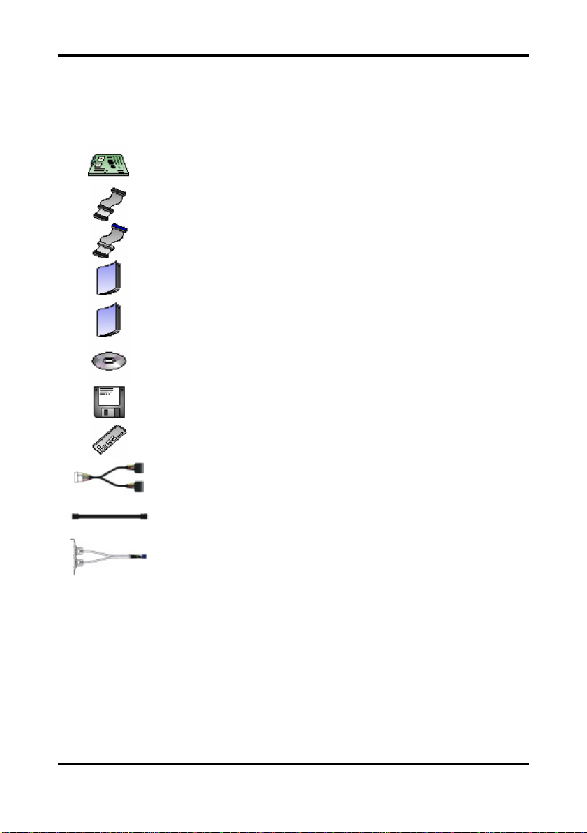
Check the package contents before you proceed.
The retail motherboard package should contain the following:
1 x Tomcat i7221A S5151 motherboard
1 x 34-Pin floppy drive cable
1 x Ultra-DMA-133/100/66/33 IDE cable
1 x Tomcat i7221A S5151User’s Manual
1 x Tomcat i7221A S5151 Quick Reference Guide
1 x TYAN driver CD
1 x Intel 82801FR (ICH6R) Driver Diskette
1 x Adaptec Driver Diskette
1 x I/O shield
2 x Serial ATA power cable
If any of these items are missing, please contact your vendor or dealer for replacement before
continuing with the installation process.
4 x Serial ATA cable
1 x USB2.0 cable
http://www.tyan.com
v

Tomcat i7221A S5151
Chapter 1: Introduction
Chapter 1: Introduction
1.1 Congratulations!
Congratulations on your purchase of the TYAN Tomcat i7221A S5151 , one of the most
powerful and versatile motherboard solutions available for Intel Prescott and Tejas processors.
Based on the Intel E7221 MCH chipset, the S5151 offers exceptional performance and
outstanding features. With the x1 PCI Express slots, onboard two Gigabit Ethernet ports,
Serial ATA RAID, four Dual-channel DDR DIMM sockets and four optional SCSI ports, the
Tomcat i7221A S5151 is ideal to fit your server/workstation needs.
For more information about this and other TYAN products, visit the TYAN Web site at
http://www.tyan.com. Product FAQs, a list of distributors and advanced BIOS information are
also available on the Web site.
1.2 Hardware Specifications
Processors
Ÿ Single Socket-T (LGA775 socket)
Ÿ Intel “P rescott” processor with EM64T
support
Ÿ 800/533MHz FSB support
Expansion Slots
Ÿ One PCI -X 64-bit 133/100/66MHz bus
supports with
? One PCI-X slot
? One proprietary 200-pin SO-DIMM
connector
Ÿ Two x1 PCI Express connectors
Ÿ One 32/33 PCI v2.3 slots
Chipset
Ÿ Intel E7221 GMCH
Ÿ Intel ICH6R South Bridge
Ÿ Intel PXH-V I/O bridge
Ÿ SMSC DME1737 Super I/O
System Management
Ÿ SMSC DME1737 w/ hardware monitoring
Ÿ One 3+1-pin CPU Fan header w/
tachometer input and temperature-sensing
auto fan control
Ÿ Four 3-pin system Fan headers (two w/
tachometer input and temperature-sensing
auto fan control)
Ÿ Temperature and voltage monitoring
Ÿ Watchdog timer
Ÿ Port 80 code display LED
Memory
Ÿ Dual memory channels
Ÿ Supports Up to 4 DDR-333/400 DIMM
Ÿ Up to 4GB unbuffered, ECC/Non-ECC
m emory
Integrated I/O Interfaces
Ÿ One floppy connector
Ÿ Four USB 2.0 ports (via cable)
Ÿ One COM2 port (via cable)
Ÿ One LPT port (via cable)
Ÿ Power/IDE/SATA LED connectors
Ÿ Two 2+2-pin headers for front panel
LAN LED
Ÿ TYAN 2 x 9 front -panel pin headers
Integrated LAN Controllers
Ÿ Two GbE LAN controllers
? Two Broadcom BCM5721 PCI
Express GbE LAN controller
? Operating at x1 PCI-E interface
? ASF 2.0 support
Ÿ One 10/100 Ethernet LAN controller
? Intel 82551
Optional modules
Ÿ M7901, SO-DIMM Ultra 320 SCSI card
? Adaptec AIC-7901X single-channel
Ultra 320 SCSI controller
? Adaptec HostRAID support w/RAID
0, 1, 10 supported
Ÿ M7902, SO-DIMM Ultra 320 SCSI card
? Adaptec AIC-7902W dual-channel
Ultra 320 SCSI controller
? Adaptec HostRAID support w/RAID
0, 1, 10 supported
Ÿ M8110 SO-DIMM SATA card
? Adaptec AIC-8110 SATA I controller
? Support up to 4-port (M8110) SATA
port running at 1.5GB/s
? Adaptec HostRAID support with
RAID 0, 1, 10 supported
1-1
http://www.tyan.com

Tomcat i7221A S5151
Chapter 1: Introduction
Integrated PCI IDE (ICH6R)
Ÿ Single channel master mode supports two
IDE devices
Ÿ Support for ATA-100/66/33 IDE drives and
ATAPI compliant devices
Integrated Serial ATA (ICH 6R)
Ÿ Four Serial ATA Host controllers embedded
Ÿ Support four Serial ports running at 1.5Gb/s
Ÿ RAID 0, 1 support
Integrated PCI Graphics
Ÿ 8-bit VGA DAC embedded the MCH to
support an analog display
Rear Panel I/O ports
Ÿ Stacked PS/2 Mouse & Keyboard ports
Ÿ One 15-pin VGA port
Ÿ One 9-pin COM port
Ÿ Two RJ45 10/100/1000 Base-T port w/
activity LED
Ÿ One RJ45 10/100 Base-T port w/activity
LED, 2x USB2.0 combo ports
TYAN reserves the right to add support or discontinue support for any OS
with or without notice.
BIOS
Ÿ Award BIOS 8Mbit Flash ROM
Ÿ Support APM 1.2 & ACPI 1.0
Ÿ PnP, DNI 2.0, WfM 2.0 Power
Management
Power
Ÿ EPS12V support, on board 4-phase
VRM
Ÿ Universal 24-pin + 8-pin power
connectors
Ÿ 4-pin auxiliary power connector
Form Factor
Ÿ ATX footprint
Ÿ 9.6” x 12.0” (243.8mm x 304.8mm)
Regulatory
Ÿ FCC Class B (Declaration of
Conformity)
Ÿ CE (Declaration of Conformity)
Ÿ BSMI
Note
1-2
http://www.tyan.com

Tomcat i7221A S5151 Chapter 2: Board Installation
Chapter 2: Board Installation
2.1 Installing the Motherboard
The Tomcat i7221A S5151 motherboard conforms fully to the ATX specification. Before
continuing with the installation, confirm that your chassis supports a standard ATX
motherboard. If you are unsure, contact your dealer for more information.
2.1.1 Installation Notes
This user manual contains important information and you should read it thoroughly before
attempting the installation procedure.
Precautions:
• Static electricity can damage components on your motherboard. Be fore touching the
product, discharge any static build up in yourself by touching a well grounded object
such as a metal water pipe or a grounded electrical appliance. TYAN re commends
putting on a good quality grounded wrist strap before removing your motherboard from
the antistatic bag.
• Disconnect your computer from the power supply before any disassembly procedure is
attempted.
• Touch the motherboard as little as possible and do not touch the bottom of the board at
• all. Bending or flexing the motherboard may break delicate components or copper tracks
on the board.
• Avoid touching any of the motherboard components.
• Place the motherboard on a grounded antistatic surface or on the antistatic bag in wh ich
the board was shipped.
• Inspect the board for damage.
Read the following sections for detailed instructions on how to install your motherboard in a
chassis and add a processor, memory, and disk drives.
Warning
Do not apply power to the board if it appears damaged.
2-1
http://www.tyan.com
Tomcat i7221A S5151 Chapter 2: Board Installation
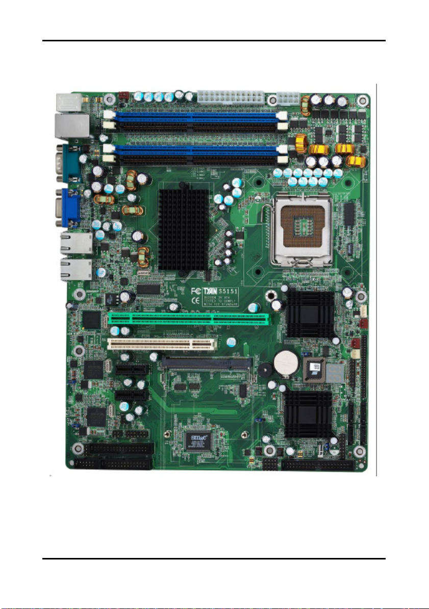
2.2 Board Image
The following is an image of the Tomcat i7221A S5151.
The above photograph is purely representative. Due to engineering updates and new
board revisions, certain components may change and or be repositioned. The picture
above may or may not look exactly like the board you received.
2-2
http://www.tyan.com
Tomcat i7221A S5151 Chapter 2: Board Installation
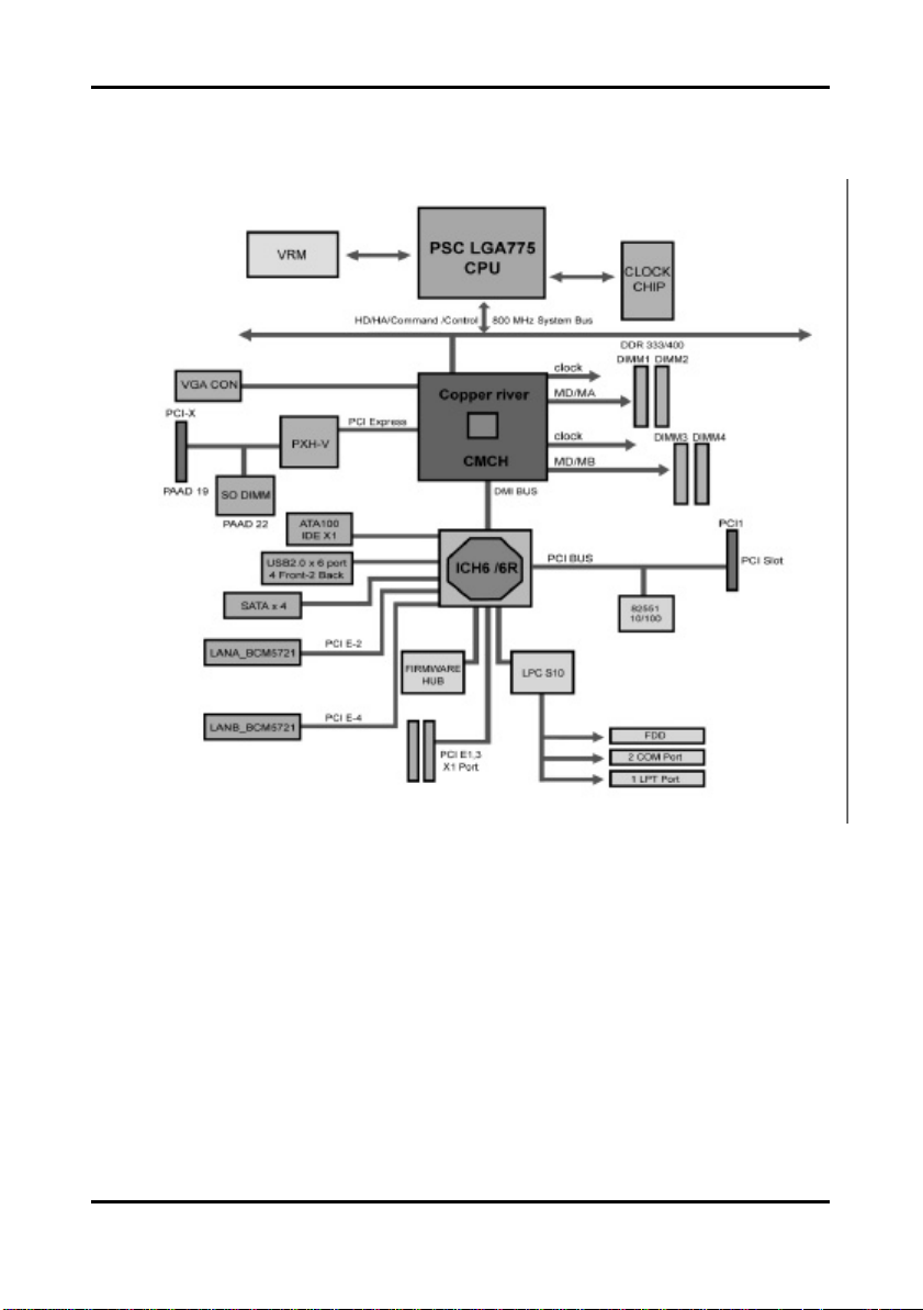
2.3 Block Diagram
The following is a block diagram of the Tomcat i7221A S5151.
2-3
http://www.tyan.com
Tomcat i7221A S5151 Chapter 2: Board Installation
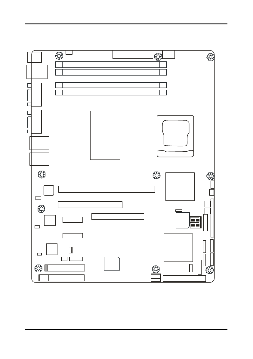
2.4 Motherboard Components
The diagram below shows the main motherboard components.
PS/2
JP8
DIMM 4
USBX2
LAN
DIMM 3
DIMM 2
COM
DIMM 1
PORT
VGA
INTEL
E7221
LAN
LAN
LAN
82551
1
JP3
X1 PCI Express
1
JP1
1
JP2
Broadcom
5721
Broadcom
5721
X1 PCI Express
J25P
JP26
1
JP4/JP5/JP6/JP7
1
LPT
This diagram represents the latest version of the motherboard available at the time of
publishing. The board you receive may or may not look exactly like the above diagram.
64-bit 133/100/66MHz PCI-X
32-bit 33MHz (5V) PCI
SO-DIMM
1 1
JP24
SMSC
FDD
I/O
Parts are not drawn to scale.
PXH-V
1
JP14
BIOS
INTEL
ICH6R
JP15
IDE J17
JP12
1
1
JP13
INTEL
1
JP22
JP23
JP17
JP18
1
JP16
SATA3
SATA1
JP9
SMDC
SATA4
SATA2
2-4
http://www.tyan.com
Tomcat i7221A S5151 Chapter 2: Board Installation
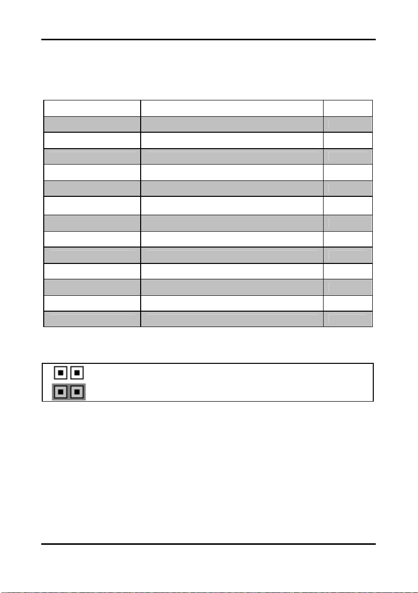
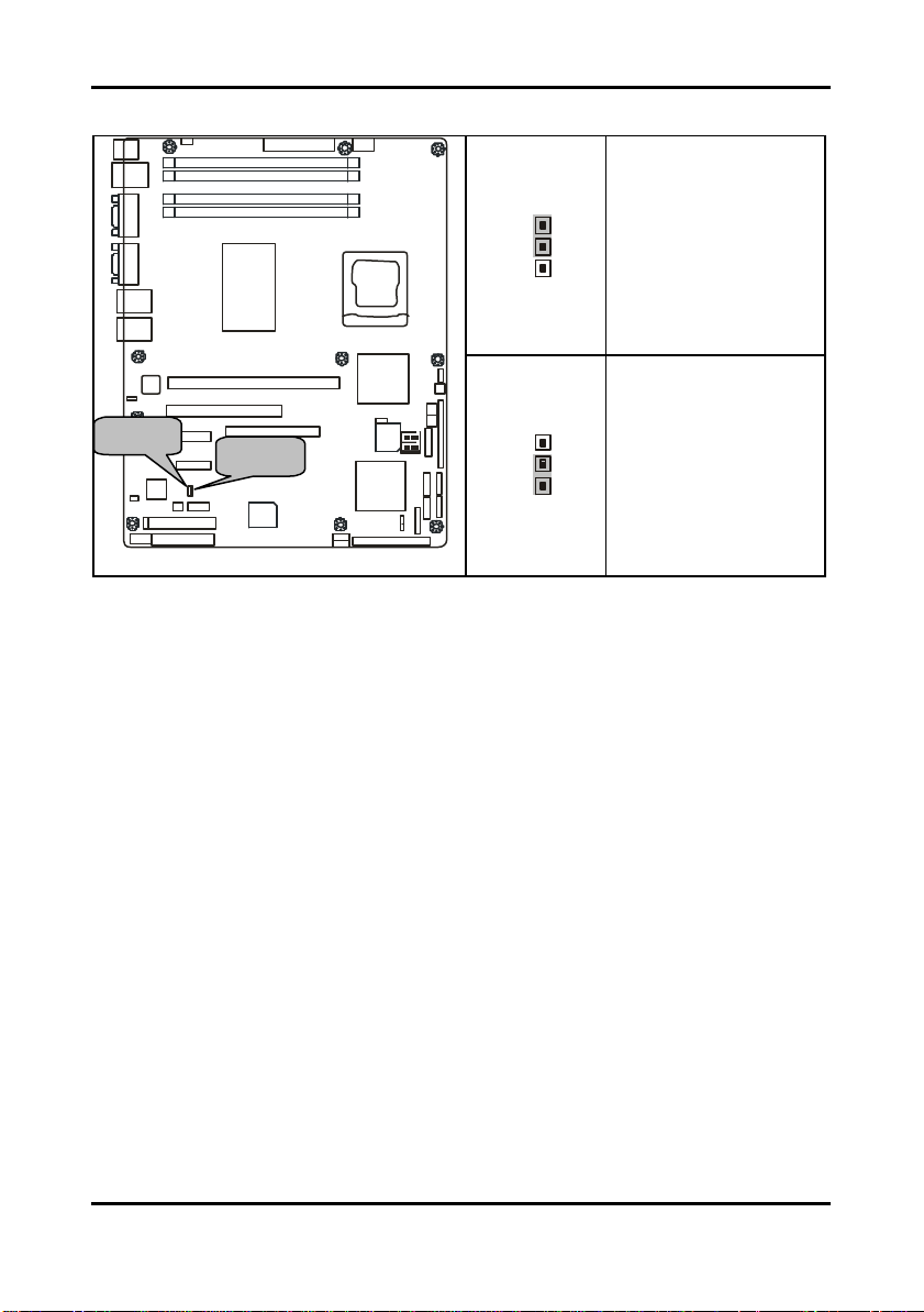
2.5 Jumpers and Connectors
Jumpers and pin headers are provided on your motherboard for configuration and connection
to peripherals. The following section shows you how to set your jumpers and use your pin
headers.
Connector Function Ref. Page
J5 COM2 port Page 2-6
J12 SO-DIMM socket Page 2-6
J20/J21/J22/J23 Serial ATA RAID connectors Page 2-7
JP1/JP2/JP3 LAN2/LAN1/LAN3 disabled headers Page 2-7
JP4/JP7 Front Panel LAN1/LAN2 Speed LED pin-headers Page 2-8
JP5/JP6
JP8 Chassis Fan connector Page 2-9
JP20 SMDC connector Page 2-12
JP12/JP13 Front panel USB2.0 connectors Page 2-10
JP14 PCI -X speed select header Page 2-12
JP15 Clear CMOS jumper Page 2-11
JP17/JP18/JP23 Front fan connectors Page 2-9
JP24/JP25 SMDC/ASF2.0 select headers Page 2-13
* Some jumpers and headers are optional and not available with the board due to the different
configurations.
Jumper Legend
Jumper OFF – open (without jumper cap)
Jumper ON – closed (with jumper cap)
Front Panel LAN1/LAN2 Link and Active LED
connectors
Page 2-8
2-5
http://www.tyan.com
Tomcat i7221A S5151 Chapter 2: Board Installation
9 1
J5 J12
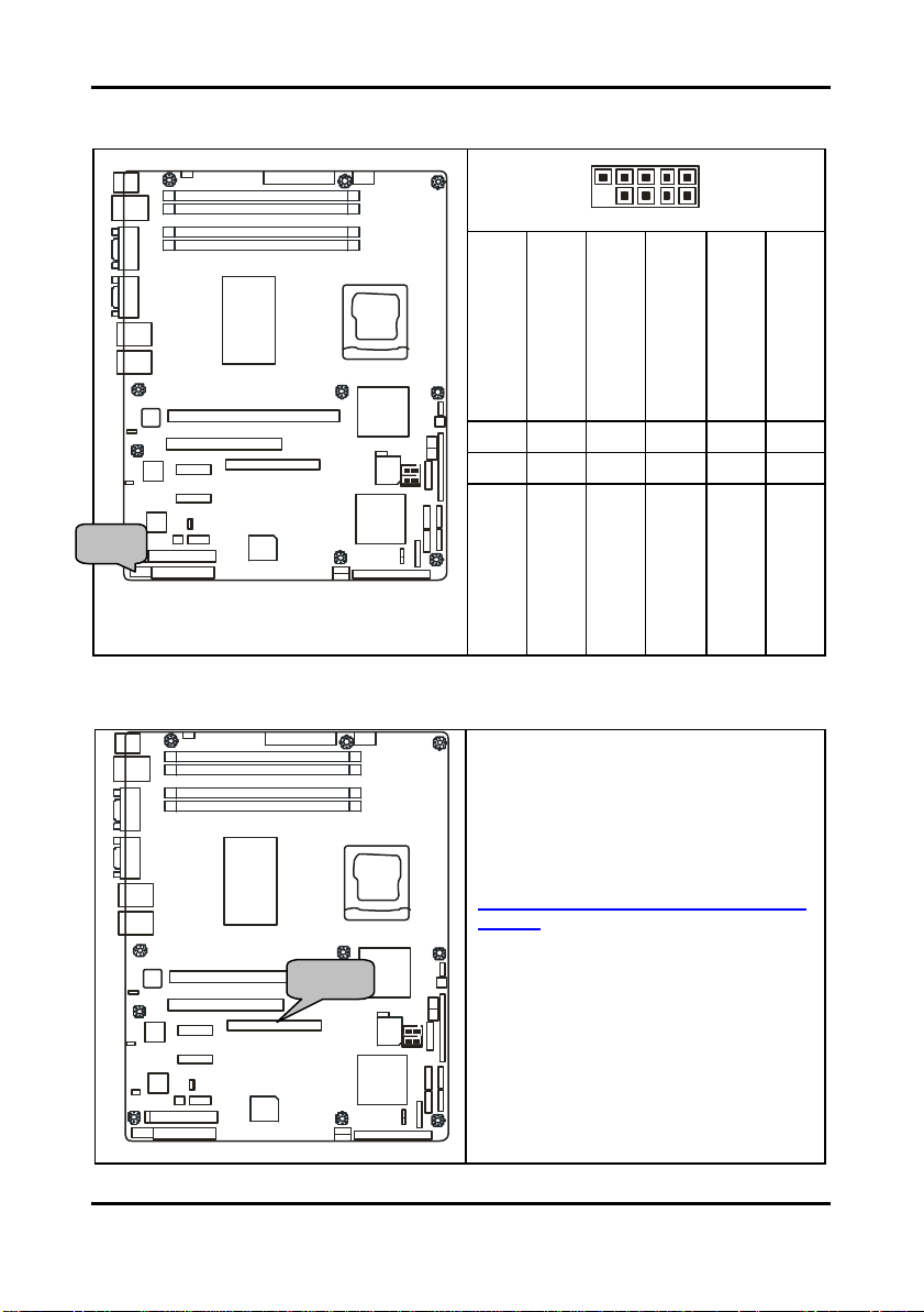
2.5.1 Com Port: J5
JP18
PS/2
USBX2
LAN
COM
PORT
DIMM 4
DIMM 3
DIMM 2
DIMM 1
10 2
VGA
LAN
JP3
JP3
JP1
JP2
JP4/JP5/JP6/JP7
LAN
LAN
82551
BROADCOM
5721
BROADCOM
BROADCOM
5721
5721
LPT
J5
64bit 133/100/66MHz PCI-X
32-bit 33MHz (5V) PCI
X1 PCI Express
X1 PCI Express
J25P JP24
FDD
INTEL
E7221
SO-DIMM
SMSC
I/O
2.5.2 SO-DIMM Socket: J12
JP18
PS/2
USBX2
LAN
COM
PORT
VGA
LAN
LAN
INTEL
E7221
DIMM 4
DIMM 3
DIMM 2
DIMM 1
Signal Description
GND
(Ground)
DTR
(Data-Terminal-Ready)
TX
(Transfer-Data)
RX
(Receive-Data)
DCD
INTEL
INTEL
JP22
PXH-V
PXH-V
JP23
Pin#
JP17
JP14
JP18
BIOS
INTEL
SATA3
ICH6R
SATA1
J19
JP13
JP12
JP15
IDE J17
Pin#
SMDC
JP16
SATA4
SATA2
9 7 6 3
10 8 5 4
RI
CTS
NC/Key
(Ring-Indicator)
(Clear-to-Send)
RTS
Signal Description
(Data Carrier Detect)
1
2
DSR
(Data-Set-Ready)
(Request-to- Send)
Connect SCSI Daughter Card
Compatible with Tyan Taro M7902 or
M7901
Also connect SO-DIMM SATA card
Compatible with Tyan Taro M8110
http://www.tyan.com/products/html/access
ory.html
JP3
JP3
JP1
JP2
JP4/JP5/JP6/JP7
J5
LAN
82551
BROADCOM
5721
BROADCOM
BROADCOM
5721
5721
32-bit 33MHz (5V) PCI
X1 PCI Express
X1 PCI Express
J25P JP24
FDD
LPT
64bit 133/100/66MHz PCI-X
SO-DIMM
SMSC
I/O
INTEL
INTEL
PXH-V
PXH-V
JP14
BIOS
INTEL
ICH6R
JP13
JP12
JP15
IDE J17
http://www.tyan.com
JP22
JP23
JP17
JP18
SMDC
JP16
SATA4
SATA3
SATA1
SATA2
J19
2-6
Tomcat i7221A S5151 Chapter 2: Board Installation
You may use any two of the four Serial
ATA ports to have the support of RAID 0
and 1 through the on board ICH6R south
1
1
1
3
3
1
Enable
SATA
JP3 JP1 JP2
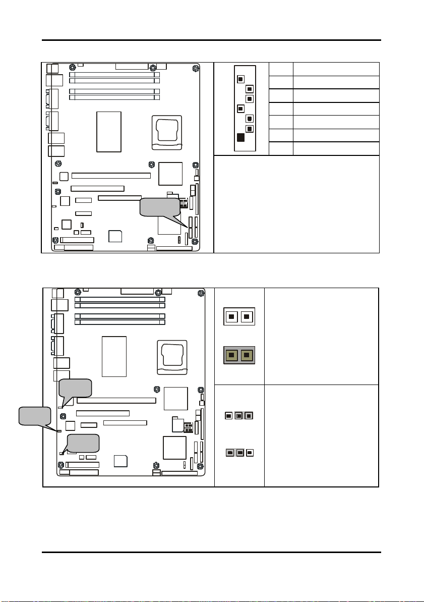
2.5.3 Serial ATA RAID Connectors: J20/J21/J22/J23 (SATA1 / SATA2 / SATA3 / SATA4)
JP18
PS/2
USBX2
LAN
COM
PORT
VGA
LAN
LAN
INTEL
E7221
DIMM 4
DIMM 3
DIMM 2
DIMM 1
7
1
7 GND
6 RXP
5 RXN
4 GND
3 TXN
2 TXP
1 GND
JP3
JP3
JP1
JP2
JP4/JP5/JP6/JP7
J5
LAN
82551
BROADCOM
5721
BROADCOM
BROADCOM
5721
5721
32-bit 33MHz (5V) PCI
X1 PCI Express
X1 PCI Express
J25P JP24
FDD
LPT
64bit 133/100/66MHz PCI-X
SO-DIMM
SMSC
I/O
INTEL
JP22
PXH-V
PXH-V
JP23
JP17
JP14
JP18
BIOS
JP16
INTEL
SATA3
ICH6R
SATA1
J19
JP13
JP12
JP15
IDE J17
Connects to the Serial ATA ready drives
via the Serial ATA cable
SMDC
SATA4
bridge chip.
SATA2
INTEL
2.5.4 LAN1/LAN2/LAN3 Disabled Headers: JP2/JP1/JP3
PS/2
USBX2
LAN
COM
PORT
VGA
LAN
JP3
JP3
JP1
JP2
JP4/JP5/JP6/JP7
LAN
J5
LAN
82551
BROADCOM
5721
BROADCOM
BROADCOM
5721
5721
JP18
32-bit 33MHz (5V) PCI
X1 PCI Express
X1 PCI Express
J25P JP24
FDD
LPT
DIMM 4
DIMM 3
DIMM 2
DIMM 1
INTEL
E7221
64bit 133/100/66MHz PCI-X
SO-DIMM
SMSC
I/O
INTEL
INTEL
JP22
PXH-V
PXH-V
JP23
JP17
JP14
JP18
BIOS
SMDC
JP16
INTEL
ICH6R
JP13
IDE J17
JP12
SATA4
SATA3
SATA1
SATA2
J19
JP15
JP1/JP2
OPEN: Disabled
CLOSED: Enabled (Default)
JP3
Pin 1-2 Closed:
(Default)
Pin 2-3 Closed: Disable
2-7
http://www.tyan.com
Tomcat i7221A S5151 Chapter 2: Board Installation
1
1
SATA4
SATA2
1
SATA4
SATA2
JP5/JP6
JP4/JP7
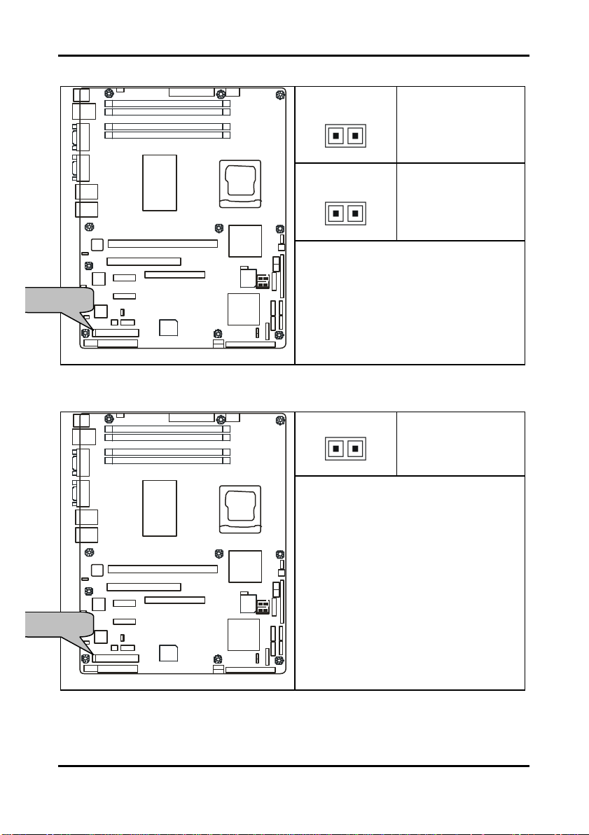
2.5.5 Front Panel LAN1/LAN2 Link and Active LED Connectors: JP5/JP6
PS/2
USBX2
LAN
COM
PORT
VGA
LAN
JP3
JP3
JP1
JP2
JP4/JP5/JP6/JP7
LAN
J5
LAN
82551
BROADCOM
5721
BROADCOM
BROADCOM
5721
5721
JP18
32-bit 33MHz (5V) PCI
X1 PCI Express
X1 PCI Express
J25P JP24
FDD
LPT
DIMM 4
DIMM 3
DIMM 2
DIMM 1
INTEL
E7221
64bit 133/100/66MHz PCI-X
SO-DIMM
SMSC
I/O
INTEL
INTEL
PXH-V
PXH-V
JP14
BIOS
INTEL
ICH6R
J19
JP13
JP12
JP15
IDE J17
JP5 (for LAN1)
Pin 1: LED+
Pin 2: LED-
JP6 (for LAN2)
Pin 1: LED+
Pin 2: LED-
JP22
JP23
JP17
Use these headers to connect with the
JP18
front panel link/activity LEDs for LAN1 and
SMDC
LAN2.
JP16
SATA3
SATA1
2.5.6 Front Panel LAN1/LAN2 Speed LED Pin-Headers: JP4/JP7
JP18
PS/2
USBX2
LAN
COM
PORT
VGA
LAN
LAN
INTEL
E7221
DIMM 4
DIMM 3
DIMM 2
DIMM 1
Pin 1: Green+
Pin 1: Orange+
Use these headers to connect with the
front panel dual color LEDs to indicate the
speed of LAN1 and LAN2.
Off = 10 LAN
JP22
JP23
Green = 100 LAN
JP17
Orange = GbE LAN
JP18
SMDC
Reference section 2.11.1 for the correct
JP16
LAN LED color definition.
SATA3
SATA1
JP4 for LAN1, JP7 for LAN2
JP3
JP3
JP1
JP2
JP4/JP5/JP6/JP7
J5
LAN
82551
BROADCOM
5721
BROADCOM
BROADCOM
5721
5721
32-bit 33MHz (5V) PCI
X1 PCI Express
X1 PCI Express
J25P JP24
FDD
LPT
64bit 133/100/66MHz PCI-X
SO-DIMM
SMSC
I/O
INTEL
INTEL
PXH-V
PXH-V
JP14
BIOS
INTEL
ICH6R
J19
JP13
JP12
JP15
IDE J17
2-8
http://www.tyan.com
Tomcat i7221A S5151 Chapter 2: Board Installation
+12V
GND
NC
+12V
GND
NC
JP8 JP23 JP17 JP18
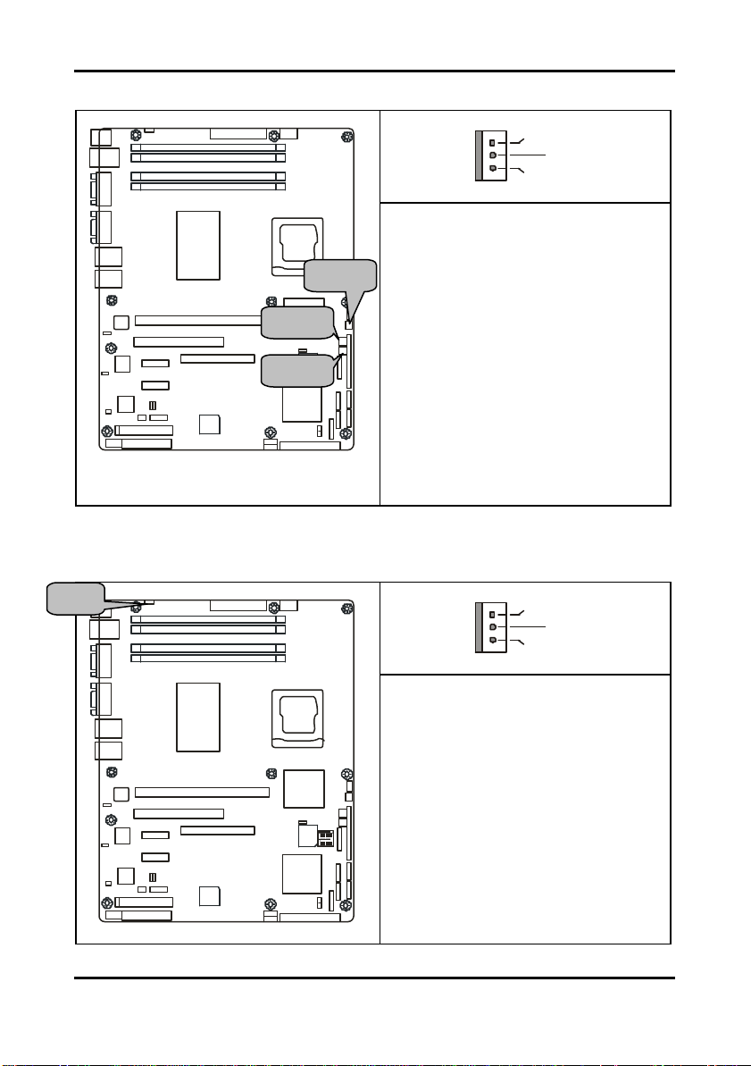
2.5.7 Front Fan Connectors: JP17/JP18/JP23
JP8
PS/2
USBX2
LAN
COM
PORT
VGA
LAN
LAN
INTEL
E7221
DIMM 4
DIMM 3
DIMM 2
DIMM 1
Use these header s to connect the chassis
cooling fans to your motherboard to keep
the system stable and reliable.
JP17 and JP23 support the tachometer
JP3
JP3
JP1
JP2
JP4/JP5/JP6/JP7
J5
LAN
82551
BROADCOM
5721
BROADCOM
BROADCOM
5721
5721
32-bit 33MHz (5V) PCI
X1 PCI Express
X1 PCI Express
J25P JP24
FDD
LPT
64bit 133/100/66MHz PCI-X
SO-DIMM
SMSC
I/O
INTEL
JP22
PXH-V
PXH-V
JP23
JP17
JP14
JP18
BIOS
JP16
INTEL
SATA3
ICH6R
SATA1
J19
JP13
JP12
JP15
IDE J17
monitoring and auto fan speed control.
SMDC
SATA4
SATA2
INTEL
2.5.8 Chassis Fan Connector: JP8
JP8
PS/2
USBX2
LAN
COM
PORT
VGA
LAN
LAN
INTEL
E7221
DIMM 4
DIMM 3
DIMM 2
DIMM 1
Use this header to connect the chassis
cooling fan to your motherboard to keep
the system at optimum performance
levels.
JP3
JP3
JP1
JP2
JP4/JP5/JP6/JP7
J5
LAN
82551
BROADCOM
5721
BROADCOM
BROADCOM
5721
5721
32-bit 33MHz (5V) PCI
X1 PCI Express
X1 PCI Express
J25P JP24
FDD
LPT
64bit 133/100/66MHz PCI-X
SO-DIMM
SMSC
I/O
INTEL
JP22
PXH-V
PXH-V
JP23
JP17
JP14
JP18
BIOS
JP16
INTEL
SATA3
ICH6R
SATA1
J19
JP13
JP12
JP15
IDE J17
These connectors support the tachometer
monitoring and auto fan speed control.
SMDC
SATA4
SATA2
INTEL
2-9
http://www.tyan.com
Tomcat i7221A S5151 Chapter 2: Board Installation
+12V
V3P3
Speed Control
Tachometer
9 1
JP22 JP13 JP12
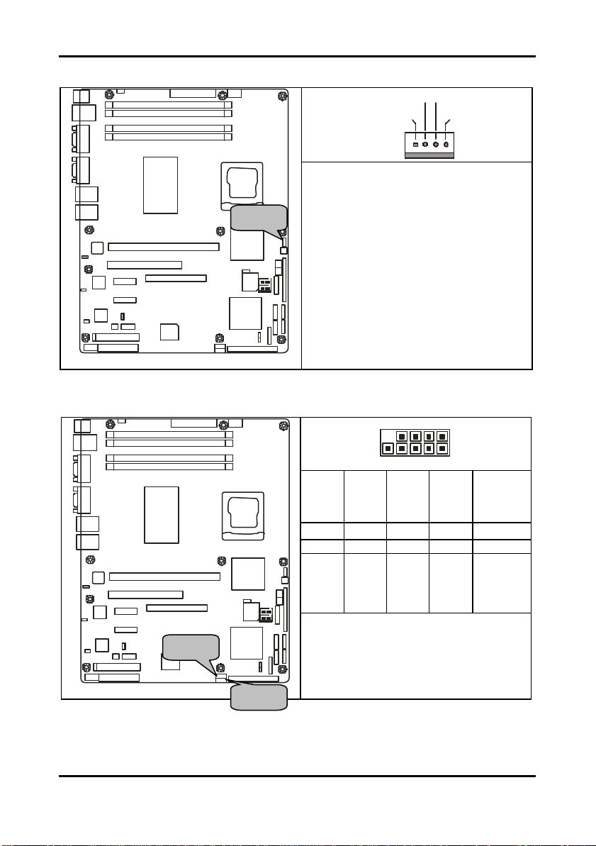
2.5.9 CPU Fan Connector: JP22
JP18
PS/2
USBX2
LAN
COM
PORT
VGA
LAN
JP3
JP3
JP1
JP2
JP4/JP5/JP6/JP7
LAN
J5
LAN
82551
BROADCOM
5721
BROADCOM
BROADCOM
5721
5721
32-bit 33MHz (5V) PCI
X1 PCI Express
X1 PCI Express
J25P JP24
FDD
LPT
DIMM 4
DIMM 3
DIMM 2
DIMM 1
INTEL
E7221
64bit 133/100/66MHz PCI-X
SO-DIMM
SMSC
I/O
Use this header to connect the processor
cooling fan to your motherboard to keep
the system stable and reliable.
INTEL
INTEL
PXH-V
PXH-V
JP14
JP18
BIOS
INTEL
SATA3
ICH6R
SATA1
J19
JP13
JP12
JP15
IDE J17
This connector supports the tachometer
JP22
monitoring and auto fan speed control.
JP23
JP17
SMDC
JP16
SATA4
SATA2
2.5.10 Front Panel USB 2.0 Connectors: JP12/JP13
JP18
PS/2
USBX2
LAN
COM
PORT
DIMM 4
DIMM 3
DIMM 2
DIMM 1
10 2
VGA
LAN
JP3
JP3
JP1
JP2
JP4/JP5/JP6/JP7
LAN
J5
LAN
82551
BROADCOM
5721
BROADCOM
BROADCOM
5721
5721
32-bit 33MHz (5V) PCI
X1 PCI Express
X1 PCI Express
J25P JP24
FDD
LPT
INTEL
E7221
64bit 133/100/66MHz PCI-X
SO-DIMM
SMSC
I/O
INTEL
INTEL
PXH-V
PXH-V
JP14
BIOS
INTEL
ICH6R
JP13
JP12
JP15
IDE J17
http://www.tyan.com
NC
GND
Data 1+
Data 1 -
+5V
9 7 5 3 1
10 8 6 4 2
JP22
JP23
JP17
JP18
JP16
SATA3
SATA1
J19
GND
SMDC
Use these headers to Connect to the USB
SATA4
devices via the enclosed USB cable.
SATA2
GND
Data 2+
Data 2 -
+5V
2-10
Tomcat i7221A S5151 Chapter 2: Board Installation
3
1
1 2
17 18
JP15 JP16
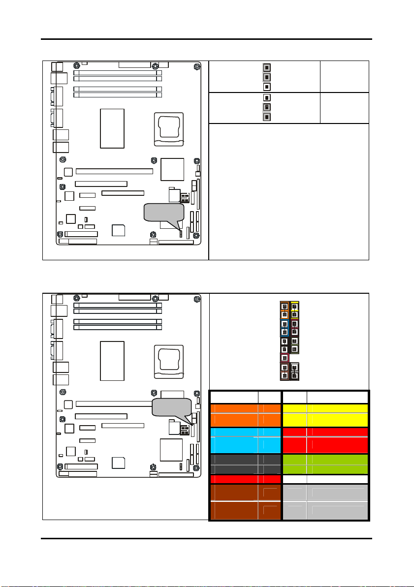
2.5.11 Clear CMOS Jumper: JP15
JP18
PS/2
USBX2
LAN
COM
PORT
DIMM 4
DIMM 3
DIMM 2
DIMM 1
1
Default
Clear
VGA
LAN
LAN
INTEL
E7221
Use this jumper when you forgot your
system/setup password or need to clear
3
system BIOS setting.
JP22
JP23
How to clear the CMOS data
JP17
- P ower off system and disconnect
JP18
SMDC
JP16
SATA4
SATA2
power supply from AC source
- Use jumper cap to close Pin_2 and 3
for several seconds to Clear CMOS
- Replace jumper cap to close Pin_1
and 2 (default setting)
- Reconnect power supply to AC
source
P ower on system
JP3
JP3
JP1
JP2
JP4/JP5/JP6/JP7
J5
LAN
82551
BROADCOM
5721
BROADCOM
BROADCOM
5721
5721
32-bit 33MHz (5V) PCI
X1 PCI Express
X1 PCI Express
J25P JP24
FDD
LPT
64bit 133/100/66MHz PCI-X
SO-DIMM
SMSC
I/O
INTEL
INTEL
PXH-V
PXH-V
JP14
BIOS
INTEL
SATA3
ICH6R
SATA1
J19
JP13
JP12
JP15
IDE J17
2.5.12 Front Panel System Connector: JP16
JP18
PS/2
USBX2
LAN
COM
PORT
DIMM 4
DIMM 3
DIMM 2
DIMM 1
VGA
LAN
JP3
JP3
JP1
JP2
JP4/JP5/JP6/JP7
LAN
J5
LAN
82551
BROADCOM
5721
BROADCOM
BROADCOM
5721
5721
32-bit 33MHz (5V) PCI
X1 PCI Express
X1 PCI Express
J25P JP24
FDD
LPT
INTEL
E7221
64bit 133/100/66MHz PCI-X
SO-DIMM
SMSC
I/O
INTEL
INTEL
PXH-V
PXH-V
JP14
JP18
BIOS
INTEL
SATA3
ICH6R
SATA1
J19
JP13
JP12
JP15
IDE J17
Function PIN PIN Function
JP22
JP23
JP17
JP16
SMDC
SATA4
SATA2
HD_LED+
HD_LED-
GND
Reset
Button
EXINT +5V
EXINT
+5VSB
SMBUS
Data
SMBUS
Clock
1 2
3 4
5 6
7 8
9 10
11 12
13 14
15 16
17 18
PLED+
PLED-
Power Button
GND
NC
GND
NC
GND
INTRU
2-11
http://www.tyan.com
Tomcat i7221A S5151 Chapter 2: Board Installation
1
3
3
1
JP20 JP14
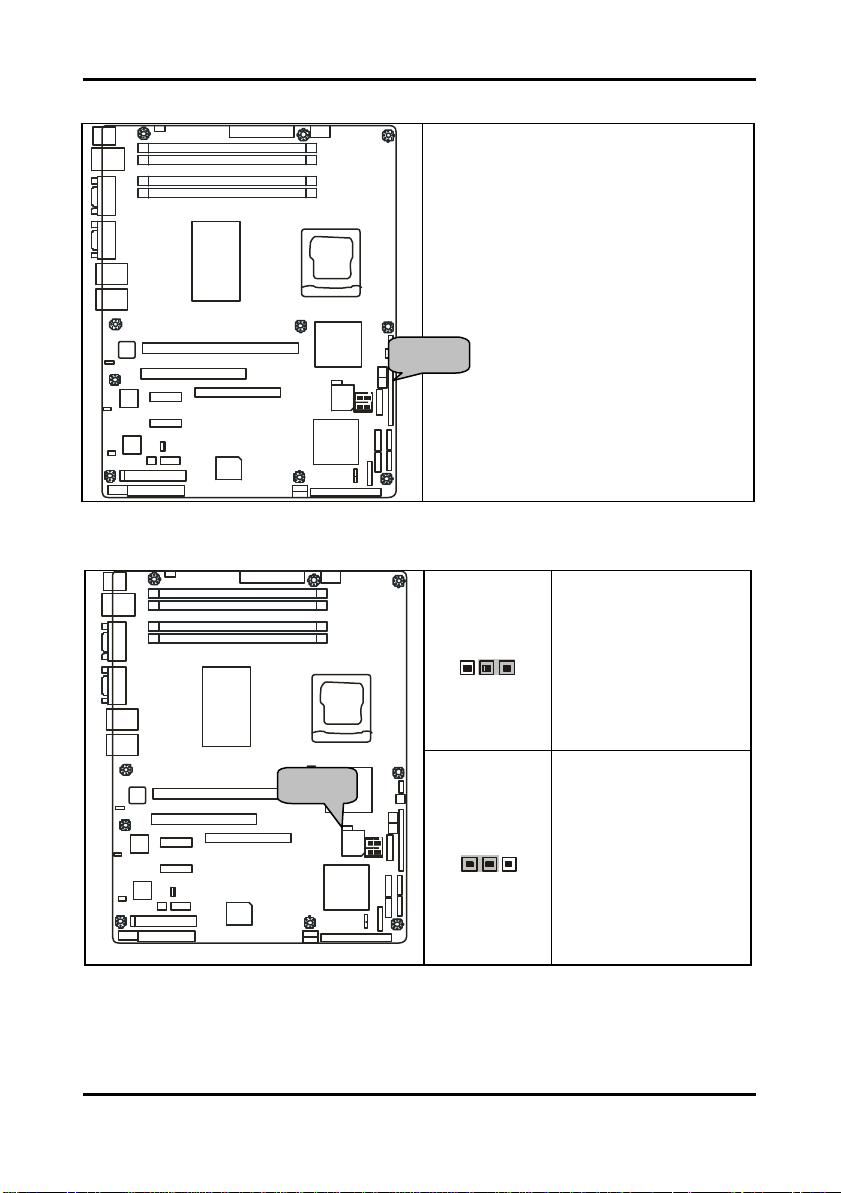
2.5.13 SMDC Connector: JP20
PS/2
USBX2
LAN
COM
PORT
VGA
LAN
JP3
JP3
JP1
JP2
JP4/JP5/JP6/JP7
LAN
J5
LAN
82551
BROADCOM
5721
BROADCOM
BROADCOM
5721
5721
JP18
32-bit 33MHz (5V) PCI
X1 PCI Express
X1 PCI Express
J25P JP24
FDD
LPT
DIMM 4
DIMM 3
DIMM 2
DIMM 1
INTEL
E7221
64bit 133/100/66MHz PCI-X
SO-DIMM
SMSC
I/O
INTEL
INTEL
PXH-V
PXH-V
JP14
JP18
BIOS
INTEL
SATA3
ICH6R
SATA1
J19
JP13
JP12
JP15
IDE J17
For connection with Tyan Server
Management Daughter Card (SMDC)
*Optional on some versions of the S5151
motherboard.
JP22
JP23
JP17
SMDC
JP16
SATA4
SATA2
2.5.14 PCI-X Speed Select Header: JP14
JP18
PS/2
USBX2
LAN
COM
PORT
VGA
LAN
LAN
INTEL
E7221
DIMM 4
DIMM 3
DIMM 2
DIMM 1
Pin 1-2 Closed: 133MHz
(Default)
JP3
JP3
JP1
JP2
JP4/JP5/JP6/JP7
J5
LAN
82551
BROADCOM
5721
BROADCOM
BROADCOM
5721
5721
32-bit 33MHz (5V) PCI
X1 PCI Express
X1 PCI Express
J25P JP24
FDD
LPT
64bit 133/100/66MHz PCI-X
SO-DIMM
SMSC
I/O
INTEL
INTEL
PXH-V
PXH-V
JP14
BIOS
INTEL
ICH6R
JP13
JP12
JP15
IDE J17
http://www.tyan.com
JP22
JP23
JP17
JP18
SMDC
JP16
SATA4
SATA3
SATA1
SATA2
J19
Pin 2-3 Closed: 100MHz
2-12
Tomcat i7221A S5151 Chapter 2: Board Installation
3
1
JP25 JP24
2.5.15 SMDC/ASF2.0 Select Headers:JP24/JP25
JP18
PS/2
USBX2
LAN
COM
PORT
VGA
LAN
JP3
JP3
JP1
JP2
JP4/JP5/JP6/JP7
LAN
J5
LAN
82551
BROADCOM
5721
BROADCOM
BROADCOM
5721
5721
32-bit 33MHz (5V) PCI
X1 PCI Express
X1 PCI Express
J25P JP24
FDD
LPT
DIMM 4
DIMM 3
DIMM 2
DIMM 1
INTEL
E7221
64bit 133/100/66MHz PCI-X
SO-DIMM
SMSC
I/O
1
Support ASF 2.0
INTEL
INTEL
JP22
PXH-V
PXH-V
JP23
JP17
JP14
JP18
BIOS
SMDC
JP16
INTEL
ICH6R
JP13
IDE J17
JP12
SATA4
SATA3
SATA1
SATA2
J19
JP15
3
Support SMDC card
2-13
http://www.tyan.com
Tomcat i7221A S5151 Chapter 2: Board Installation
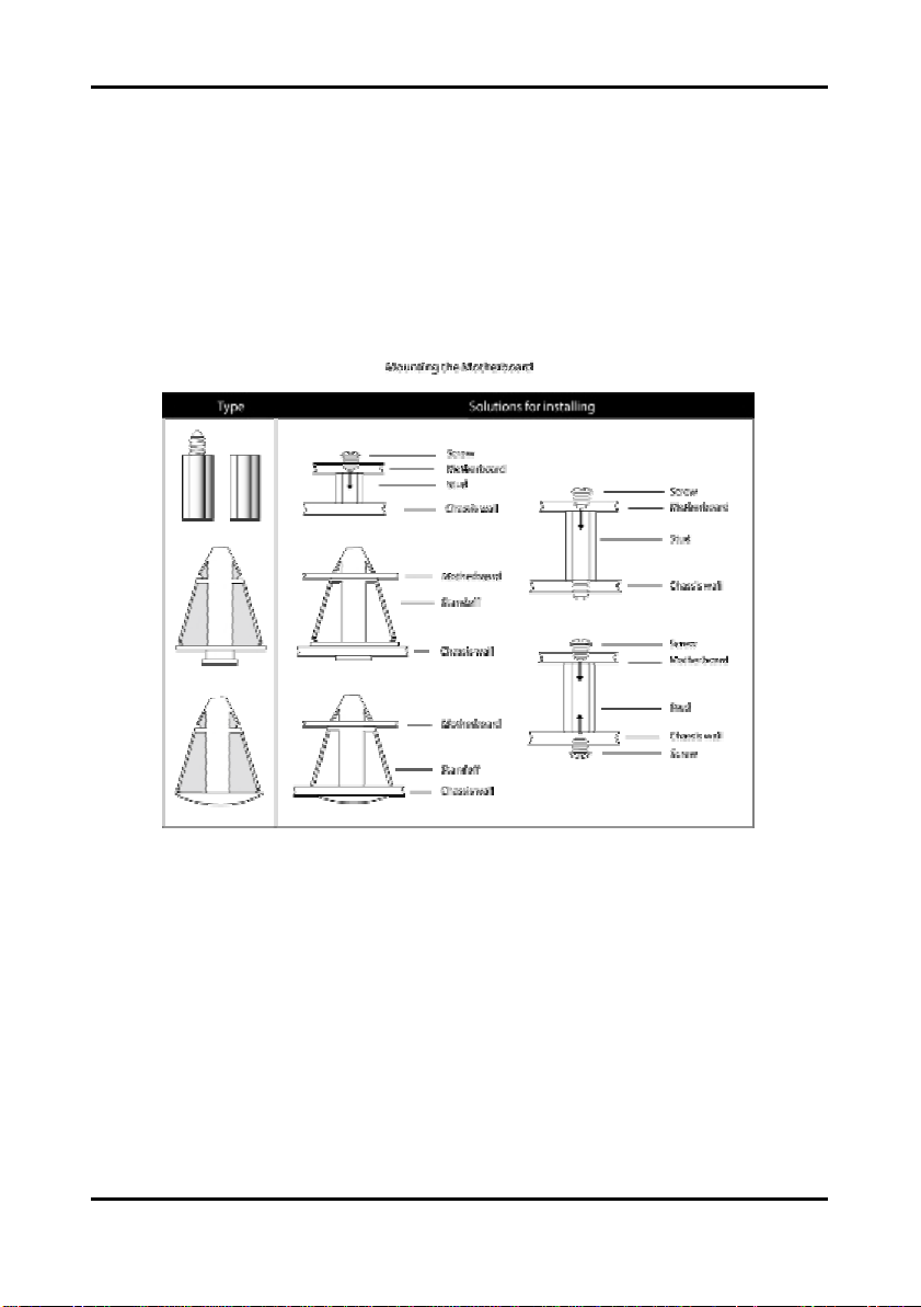
2.6 Mounting the Motherboard
Before installing your motherboard, ensure that your chassis is fully com patible. The Tomcat
i7221A S5151 motherboard conforms fully to the ATX specification. Your chassis should
include preinstalled mounting posts that match exactly with the mounting holes in the
motherboard. Lay the motherboard on top of the mounting holes to ensure that all the
necessary mounting posts exist in your chassis and that they match the mounting holes on
the motherboard.
Some chassis’ include plastic studs instead of metal. Although the plastic studs are usable,
TYAN recommends using metal studs with screws that will fasten the motherboard more
securely in place.
See the diagram below for some examples of typical motherboard fixing studs.
TIP: Use metal studs if possible, as they hold the motherboard into place more securely than
plastic standoffs.
2-14
http://www.tyan.com
Tomcat i7221A S5151 Chapter 2: Board Installation
DDR Unbuffered ECC
DDR Unbuffered
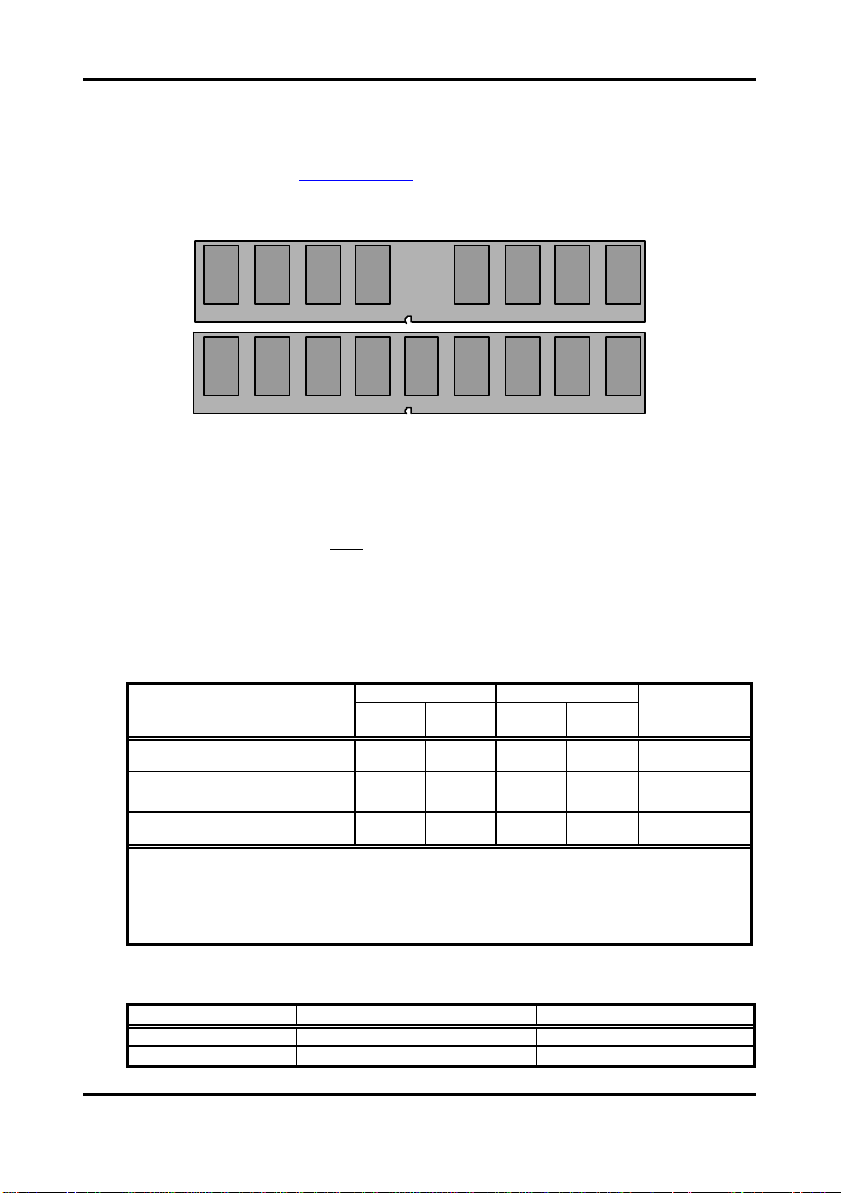
2.7 Installing Memory
Before installing memory, ensure that the mem ory you have is compatible with the
motherboard and processor. PC2700/PC3200 (DDR333/DDR400) modules are required.
Check the TYAN Web site at: www.tyan.com for details of the type of mem ory recommended
for your motherboard.
The following diagram shows common types of memory modules.
Key points to note before installing memory:
• 128MB, 256MB, 512MB and 1GB Non-Reg/ECC or Non-Reg/N on-ECC
PC2700/PC3200 DDR memory modules are supported
• All installed memory will be automatically detected and no jumpers or settings need
to be set.
• The Tomcat i7221A S5151 supports up to 4GB of memory
• Registered Memory is NOT supported .
• You can install either single or double-sided modules on this motherboard. Each
DIMM can work in single-channel mode or dual-channel mode. Please note that
memory modules of the same type and density are required while using dualchannel DDR. Mismatched memory may cause system instability.
Refer to the following table for details of dual-channel DDR.
Dual -Channel Mode
Two DIMM Symmetrical
Population
Two DIMM Symmetrical
Population
Four DIMM Symmetrical
Population
Note
1. ü = Installing 128MB ~ 1GB Memory modules
2. Symmetrical DIMM’s must be identical
- Same DRAM Technology, eg 128M-bit, 256-bit, etc.
- Same DRAM bus width, eg x8 or x16
- Matched Sided DIMM ’s (Single Sided or Double Sided)
Channel A Channel B
DIMM1
(Blue)
DIMM2
(Black)
ü ü 256MB~2GB
ü ü 256MB~2GB
ü ü ü ü 512MB~4GB
DIMM3
(Blue)
DIMM4
(Black)
• Supported System Bus Frequency and Memory Speed Combinations
CPU FSB DDR DIMM Type Memory Frequency
800MHz PC2700 or PC3200 333MHz or 400MHz
533MHz PC2700 333MHz
2-15
http://www.tyan.com
System
Density
Tomcat i7221A S5151 Chapter 2: Board Installation
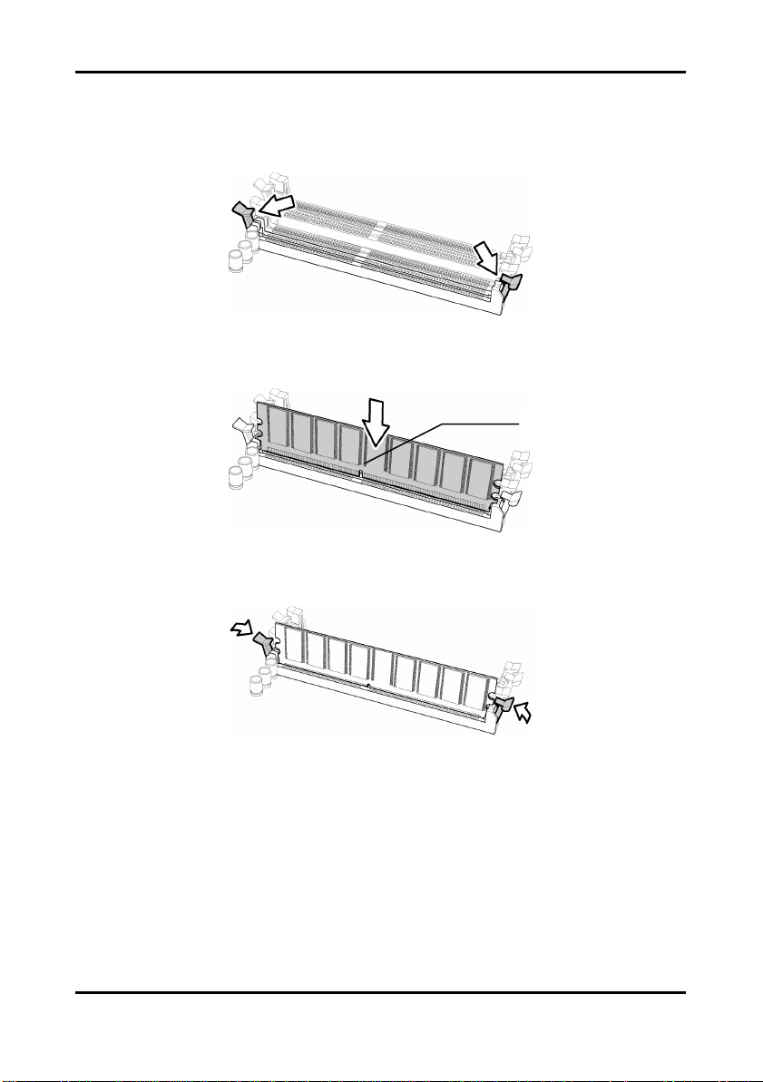
2.7.1 Memory Installation Procedure
Follow these instructions to install memory modules into the Tomcat i7221A S5151.
1. Press the locking levers in the direction shown in the following illustration.
2. Align the memory module with the socket. The memory module is keyed to fit only one
way in the socket.
Key slot
3. Seat the module firmly into the socket by gently pressing down until it sits flush with the
socket. The locking levers pop up into place.
2-16
http://www.tyan.com
Tomcat i7221A S5151 Chapter 2: Board Installation
2.8 Installing the Processor and Cooling Fan
Your Tomcat i7221A S5151 supports the latest processor technologies from Intel. Check the
TYAN website for latest processor support:
http://www.tyan.com
Processor Installation
The processor should be installed carefully. Make sure you are wearing an antistatic strap and
handle the processor as little as possible.
Follow these instructions to install your processor
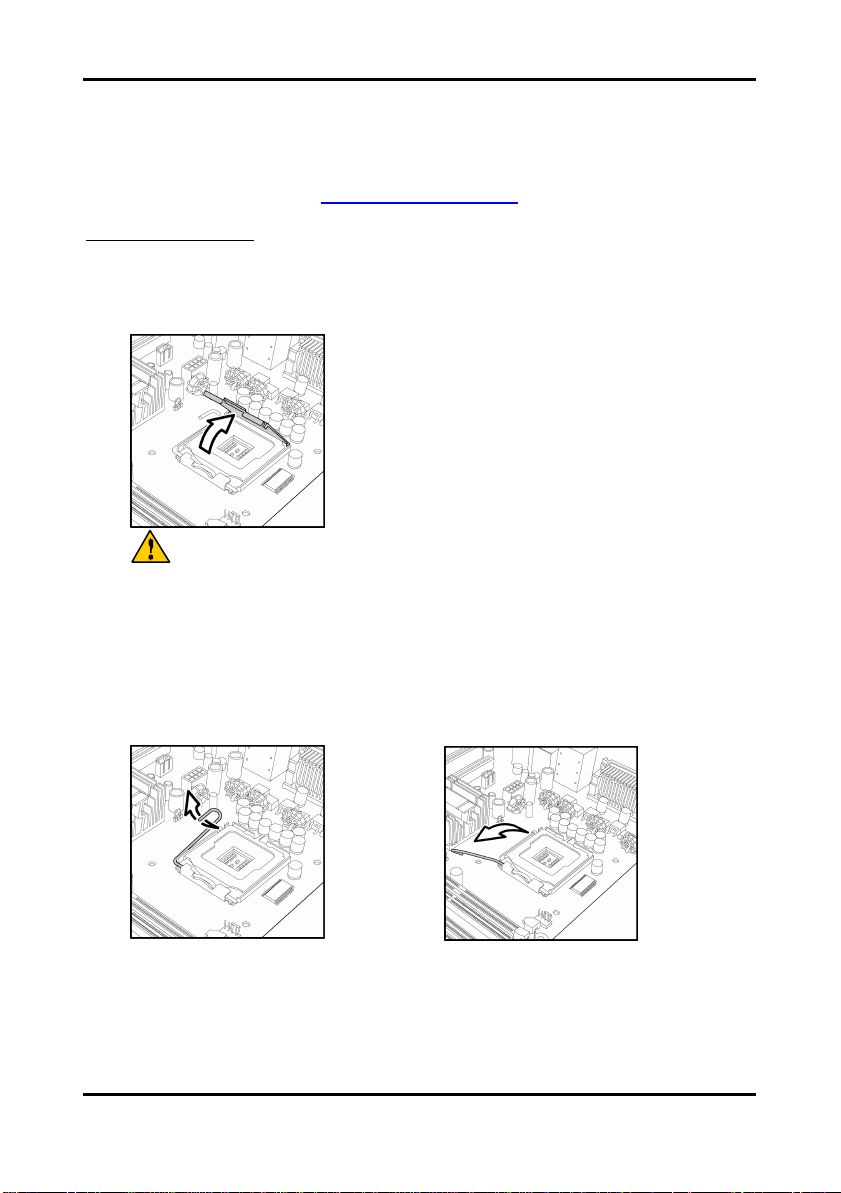
1. Locate the processor socket on the motherboard and lift the protective cover off as
shown.
WARNING:
This new processor socket designed by
Intel is easily damaged. The processor has
to be installed very carefully to prevent the
contact pins of the socket from breaking. It
is strongly recommended that the
processor installation job to be handled by
an experienced technician.
2. Pull the locking lever out of it’s locked position and let it spring into the open position.
2-17
http://www.tyan.com
Tomcat i7221A S5151 Chapter 2: Board Installation
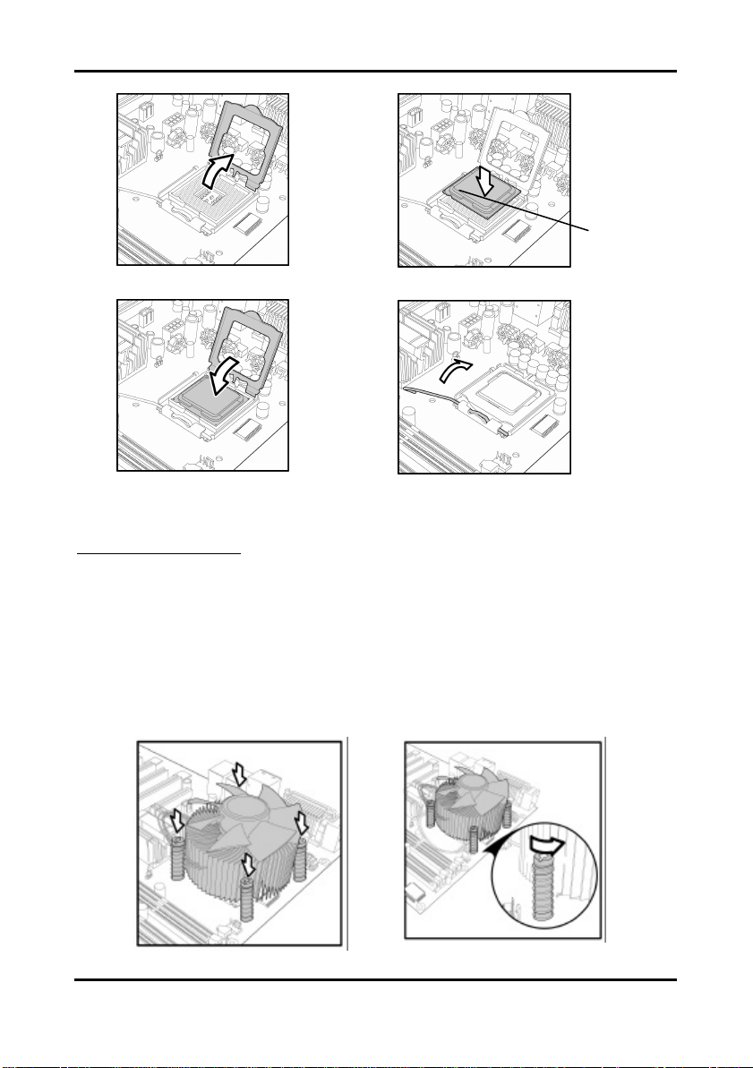
Pin 1
3. Lift the metal cover to expose the socket interior and place the socket in as shown.
4. Close the cover and return the locking lever to its locked position.
Cooling Fan Installation
After you have installed the processor, the heatsink should be installed to ensure that the
processor runs efficiently and does not overheat. Use the heatsink supplied for best results.
Follow these instructions to install the heatsink shown.
1. Apply some thermal compound (also called heatsink compound or thermal grease) to
the top of the processor. Try and apply a thin, even layer over the top of the processor.
2. Align the heatsink with the four holes around the processor socket.
3. Press the heatsink down until the four screws are se curely seated in the holes.
4. Use screw drive to secure the four screws.
2-18
http://www.tyan.com
Tomcat i7221A S5151 Chapter 2: Board Installation
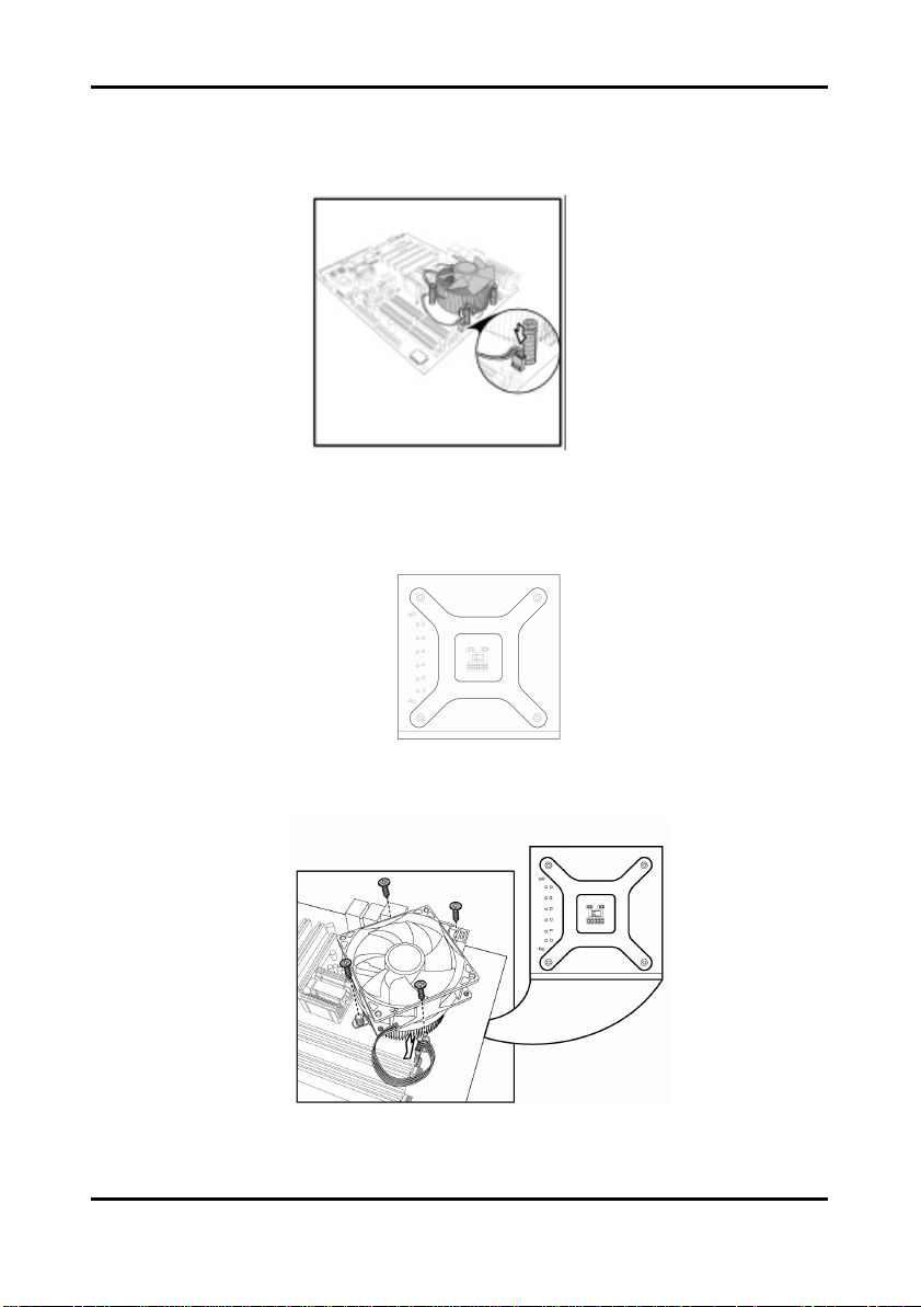
To remove the heatsink you will need to twist each of the black locking pegs until they spring
up and unlock the heatsink from the motherboard.
Remember to connect the power supply for the fan to complete the installation.
Some heat sinks require a bracket to be installed beneath the motherboard before the heat
sink is placed on the top side of the motherboard. To install a heat sink like this:
1 Turn the motherboard upside down and place the rear bracket in position with the
mounting posts poking through the corresponding holes in the motherboard.
2 Turn the motherboard the right way up, holding the bracket in place.
3 Place the heat sink assembly on top of the processor.
It should match up with the mounting holes on the rear bracket.
4 Screw the heat sink assembly into place.
If there is a fan on the heat sink you will need to connect the power lead for the fan to
one of the fan power supply pin headers on the motherboard.
2-19
http://www.tyan.com
Tomcat i7221A S5151 Chapter 2: Board Installation
Colored cable denotes pin 1
2.9 Installing Drive Cables
TIP: IDE and FDD connectors are “keyed” to only allow insertion only one way. S5151
m otherboard has two on-board IDE channels, each supporting two drives.
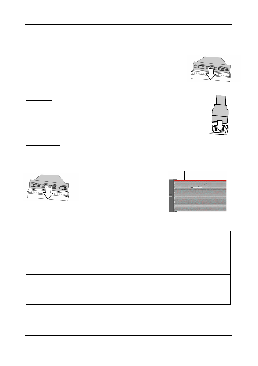
IDE Cable
When connecting to an IDE cable to a drive, Pin 1 on the IDE cable
(usually designated by a colored wire) should be closest to the drive
power connector.
The blue end of the cable connects directly to the motherboard and the
black end of the connector goe s to the IDE device.
Serial ATA
Attaching Serial ATA cables to the Serial ATA connectors are illustrated below:
Plug in one end of the Serial ATA cable into the motherboard Serial ATA
connector, and the other end into the drive. Each standard Serial ATA cable has
two connectors, one at each end. Connectors are the same on both ends.
Floppy Drives
Floppy disk drive (FDD) cables are installed the same way as IDE cables. Usually connectors
are keyed to prevent insertion the wrong way. In most cases the cable should be inserted into
the drive with pin 1 closest to the power input. FDD cables usually have a single red wire that
marks pin 1. See the diagram below.
Symptoms of incorrectly installed floppy drives
Drive is not automatically detected
Drive Fail message at b oot up
Drive does not power on
Drive activity light is constantly on
Usually caused by faulty cables, cables put in
backwards or a faulty floppy drive. Try another
floppy drive or try replacing the cable. Check to
see if the onboard floppy controller is enabled in
the BIOS setup.
The cable, floppy drive or motherboard may be
faulty. Try another drive or cable.
Check power cable and cabling. A faulty power
supply or drive cable could be the problem.
Usually signifies that the cable on the drive is
inserted backwards. Reverse the cable at the
floppy drive end and try again.
2-20
http://www.tyan.com
Tomcat i7221A S5151 Chapter 2: Board Installation
X1 PCI Express Slot
2.10 Installing Expansion Cards
Before installing add-in cards, you should ensure that they are fully compatible with your
motherboard. For this rea son, we’ve provided the diagrams below, showing the expansion
slots that appear on your motherboard.
PCI -X Slot
PCI Slot
Expansion cards should be pushed firmly into the appropriate slot. Excessive force can
damage both the card and the motherboard and care sh ould be taken.
Notes
Unplug the power connector to the motherboard before performing
system hardware changes, to avoid damaging the board or expansion
cards
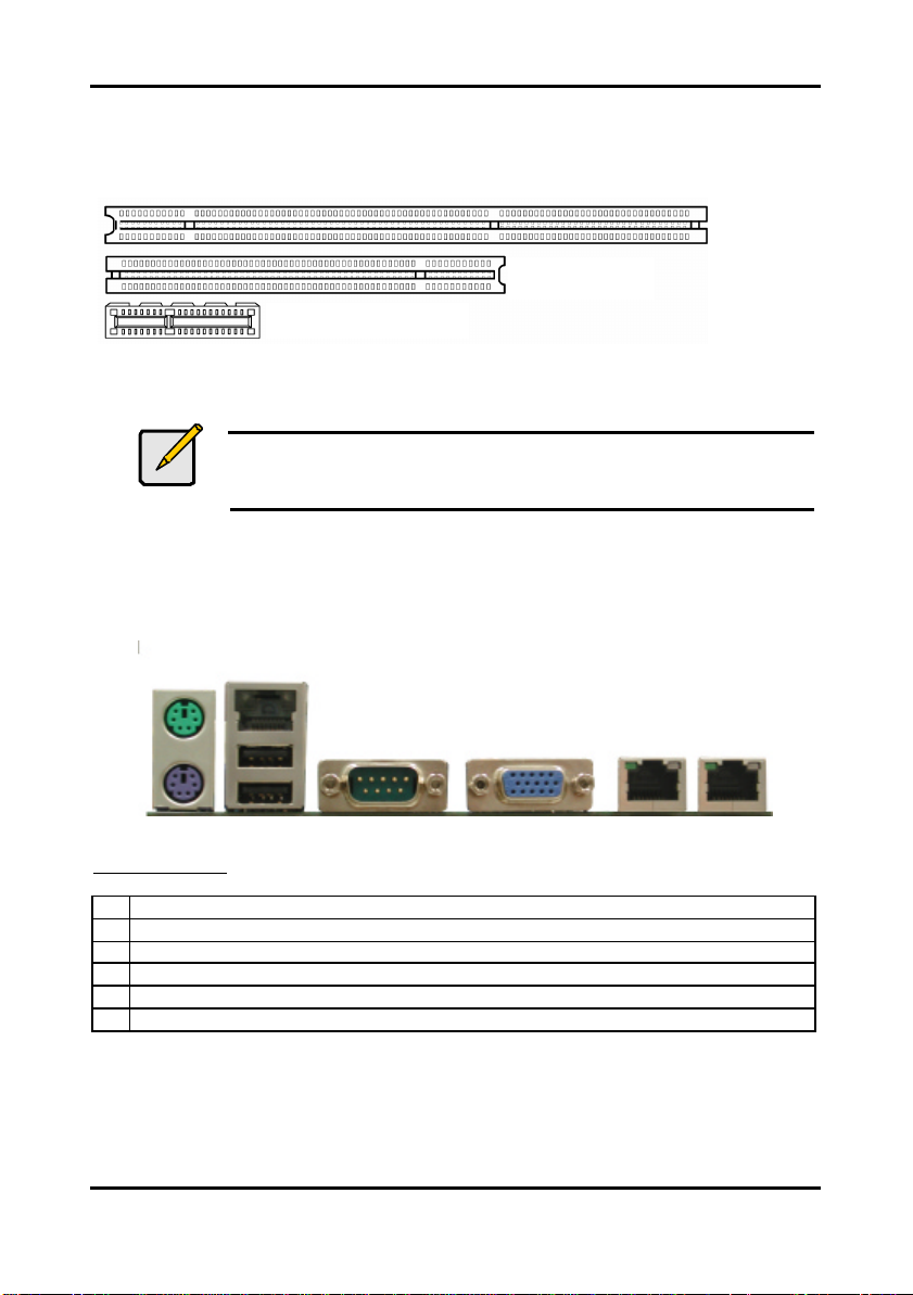
2.11 Connecting External Devices
Your new motherboard supports a number of different interfaces for connec ting peripherals.
See the diagram below. Some I/O ports may not be available with the board due to the
different configuration.
A B C D E F
Port definitions:
A PS2 mouse port (green)/ keyboard port (purple)
B 10/100 LAN + USB 2.0 ports x 2
C Serial port (green)
D VGA port (blue)
E LAN2 Gigabit Ethernet port
F LAN1 Gigabit Ethernet port
Peripheral devices can be plugged straight into any of these ports but sof tware may be
required to complete the installation.
2-21
http://www.tyan.com
Tomcat i7221A S5151 Chapter 2: Board Installation
2.11.1 Onboard LAN LED Color Definition
The two onboard Ethernet ports have green and yellow LED’s to indicate LAN status. The
chart below illustrates the different LED states.
10/100/1000 Mbps LAN Link/Activity LED Scheme
Left LED Right LED
10 Mbps
100 Mbps
1000 Mbps
No Link Off Off
Link Green Off
Active Blinking Green Off
Link Green Green
Active Blinking Green Green
Link Green Orange
Active Blinking Green Orange
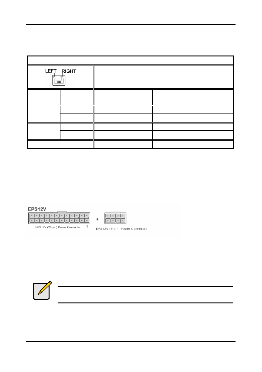
2.12 Installing the Power Supply
There are two power connectors on your Tomcat i7221A S5151. The Tomcat i7221A S5151
requires that you have an EPS12V power supply that has a 24-pin and an 8-pin power
connector. Please be aware that ATX 2.x, ATX12V and ATXGES power supplies are not
compatible with the board and can damage the motherboard and/or CPU(s).
Disconnect power supply from electrical outlet
1. Connect the EP12V 8-pin power connector
2. Connect the EP12V 24-pin power connector
3. Connect power cable to power supply to power outlet
Make sure you have connected both connectors before attempting to apply power to the
board.
Note
Unplug the power supply before plugging in the 24-pin and 8-pin power
cables to motherboard.
2-22
http://www.tyan.com

Tomcat i7221A S5151 Chapter 2: Board Installation
2.13 Finishing Up
Before closing up your chassis, make sure that all cables and wires are connected properly,
especially IDE cables and most importantly, jumpers. You may have difficulty powering on
your system if the motherboard jumpers are not set corre ctly.
If you experience difficulty, you can find help by asking your vendor for assistance. If they are
not available for assistance, please find setup information and documentation online at our
website (www.tyan.com) or by calling your vendor’s support line.
2-23
http://www.tyan.com

Tomcat i7221A S5151 Chapter 3: BIOS Setup
Chapter 3: BIOS Setup
3.1 About the BIOS
The BIOS is the basic input/output system, the firmware on the motherboard that enables your
hardware to interface with your software. This chapter describes different settings for the
BIOS that can be used to configure your system.
The BIOS section of this manual is subject to change without notice and is provided for
reference purposes only. The settings and con figurations of the BIOS are current at the time of
print, and therefore may not match exactly what is displayed on screen.
This section describes the BIOS setup program. The setup program lets you modify basic
configuration settings. The settings are then stored in a dedicated, battery-backed memory
(called NVRAM) that retains the information when the power is turned off.
This motherboard’s BIOS is a customized version of the industry -standard BIOS for IBM PC
AT-compatible personal computers. The BIOS provides critical, low-level support for the
system’s central processing unit (CPU), memory, and I/O subsystems.
This BIOS has been customized by adding important features such as virus and password
protection, power management, and chipset “tuning” features that control the system. This
section will guide you through the process of configuring the BIOS for your system setup.
3.1.1 Starting Setup
The BIOS is immediately activated when you turn on the computer. The BIOS reads system
con figuration in CMOS RAM and begins the process of checking out the system and
configuring it through the Power-On-Self-Test (POST).
When these preliminary tests are complete, the BIOS searches for an operating system on
one of the system’s data storage devices (hard drive, CD-ROM, etc). If one is found, the BIOS
will launch that operating system and hand control over to it. You can enter the BIOS setup by
pressing the [Delete] key when the machine boots up and begins to show the memory count.
3.1.2 Setup Basics
The table below shows how to navigate in the setup program using the keyboard.
3.1.3 Getting Help
Pressing [F1] displays a small help window that describes the appropriate keys to use and the
possible selections for the highlighted item. To exit the Help Window, press [ESC] or the [F1]
key again.
Key Function
Tab Moves from one selection to the next
Left/Right Arrow Keys Changes from one menu to the next
Up/Down Arrow Keys Moves between selections
Enter Opens highlighted section
PgUp/PgDn Keys Changes settings.
3-1
http://www.tyan.com

Tomcat i7221A S5151 Chapter 3: BIOS Setup
3.1.4 In Case of Problems
If you have trouble booting the computer after making and saving changes with the BIOS
setup program, restart the com puter by holding the power button down until the computer
shuts off (usually within 4 seconds); resetting by pressing CTRL-ALT-DEL; or clearing the
CMOS.
Only alter settings that you thoroughly understand. In particular, do not change settings in the
Chipset section unless you are sure of the outcome. TYAN or your system manufacturer has
carefully chosen the chipset defaults for best performance and reliability. Even a small change
to the Chipset setup options may cause the system to become unstable or unu sable.
3.1.5 Setup Variations
While the basic look and function of the BIOS setup remains more or less the same for most
systems, the appearance of your Setup screen may differ from the charts shown in this
section. Each system design and chipset com bination requires a custom configuration. In
addition, the final appearance of the Setup program depends on the system designer. Your
system designer may decide that certain items should not be available for user configuration,
and remove them from the BIOS setup program.
Note
On the following pages, options written in bold type represent the BIOS
Setup default.
3.2 Main BIOS Setup
When you enter Phoenix - AwardBIOS CMOS Setup Utility, the following screen will appear as
below:
Standard CMOS Features
Use this menu for basic system configuration.
Advanced BIOS Features
Use this menu to set the Advanced Features available on your system.
Advanced Chipset Features
Use this menu to change the values in the chipset registers and optimize your system's
performance.
3-2
http://www.tyan.com

Tomcat i7221A S5151 Chapter 3: BIOS Setup
Integrated Peripherals
Use this menu to specify your settings for integrated peripherals.
Power Management Setup
Use this menu to specify your settings for power management.
PnP / PCI Configuration
This entry appears if your system supports PnP / PCI.
PC Health Status
Use this menu to show your system temperature, speed and voltage status.
Frequency/Voltage Control
Use this menu to specify your settings for fr equency/voltage control.
Load Fail-Safe Defaults
Use this menu to load the BIOS default values for the minimal/stable performance for your
system to operate.
Load Optimized Defaults
Use this menu to load the BIOS default values that are factory settings for optimal
performance system operations. While Award has designed the custom BIOS to maximize
performance, the factory has the right to change these defaults to meet their needs.
Supervisor / User Password
Use this menu to set User and Supervisor Passwords.
Save & Exit Setup
Save CMOS value changes to CMOS and exit setup.
Exit Without Saving
Abandon all CMOS value changes and exit setup.
3-3
http://www.tyan.com

Tomcat i7221A S5151 Chapter 3: BIOS Setup
3.3 Standard CMOS Features
In this section, you can alter general features such as the date and time, as well as access to
the IDE configuration options. Note that the options listed below are for options that can
directly be changed within the Main Setup screen. Users use the arrow keys to highlight the
item and then use the <PgUp> or <PgDn> keys to select the value you want in each item.
Date / Time Setup
System Date: Adjusts the system date.
MM Months
DD Days
YYYY Years
System Time: Adjusts the system clock.
HH Hours (24hr. format)
MM Minutes
SS Seconds
IDE Master / Slave Setup
Computer detects IDE drive type from drive C to drive F.
None / Auto / Manual
3-4
http://www.tyan.com

Tomcat i7221A S5151 Chapter 3: BIOS Setup
Drive A
Defines the floppy drive type.
Video
Defines the video display mode.
Halt On
Determines if the computer should stop when an error is detected during power up.
None / 360K, 5.25in / 1.2M, 5.25in / 720K, 3.5in / 1.44M, 3.5in / 2.88M, 3.5in
EGA/VGA / CGA 40 / CGA 80 / MONO
No Errors / All Errors / All, But Keyboard / All, But Diskette / All, But Disk/Key
3.4 Advanced BIOS Features
In Advanced BIOS features, you will be able to adjust many feature s that affect system speed
and boot-up options.
Boot Up Floppy Seek
During Power -On Self-Test (POST), BIOS will determine if the floppy disk drive installed is 40
or 80 tracks.
Boot Up NumLock Status
This option, when enabled, automatically turns on your NumLoc k key when the system is
booted. This is a matter of personal taste.
Gate A20 Option
This feature determines how Gate A20 is used to address memory above 1MB. When this
option is set to Fast, the motherboard chipset controls the operation of Gate A20. But when
set to Normal, a pin in the keyboard controller controls Gate A20. Setting Gate A20 to Fast
improves memory access speed and thus, overall system speed, especially with OS/2 and
Windows.
This is because OS/2 and Windows enter and leave protected mode via the BIOS, so Gate
A20 needs to switch often from enabled to disabled and back again. Setting this feature to
Fast im proves memory access performance above 1MB because the chipset is much faster at
switching Gate A20 than the keyboard controller. It is recommended that you set it to Fast for
faster memory accesses.
Enabled / Disabled
On / Off
Normal / Fast
3-5
http://www.tyan.com

Tomcat i7221A S5151 Chapter 3: BIOS Setup
Typematic Rate Setting
This feature enables you to control the keystroke repeat rate when you depress a key
continuously. When enabled, you can manually adjust the settings using the two typematic
controls (Typematic Rate and Typematic Delay). If disabled, the BIOS will use the default
setting.
Typematic Rate (Chars/Sec)
Defines how many characters are repeated per second when holding down a key on the
keyboard:
Typematic Delay (Msec)
Defines the delay (in milli-seconds) that occurs at keystroke before that key will start to repeat.
Security Option
Setting this option to System will set the BIOS to ask for the password each time the system
boots up.
If you choose Setup, then the password is only required for access into the BIOS setup
menus.
OS Select For DRAM > 64MB
This BIOS feature determines how systems with more than 64MB of memory are managed. A
wrong setting can cause problems like erroneous memory detection.
If you are using an older version of the IBM OS/2 operating system, you should select OS/2.
If you are using the IBM OS/2 Warp v3.0 or higher operating system, you should select NonOS/2.
If you are using an older version of the IBM OS/2 operating system but have already installed
all the relevant IBM Fix -Paks, you should select Non-OS/2.
Users of non-OS/2 operating systems (like Microsoft Windows 2003) should select the NonOS2 option.
Report No FDD For WIN 95
Set this option to Yes if you are using Windows 95/98 without a floppy to release IRQ6 (this is
required to pass Windows 95/98's SCT test and get the logo).
Small Logo (EPA) Show
Toggles the display of the EPA Energy Star logo at POST.
Enabled / Disabled
6 / 8 / 10 / 12 / 15 / 20 / 24 / 30
250 / 500 / 750 / 1000
Setup / System
Non-OS2 / OS2
No / Yes
Enabled / Disabled
3-6
http://www.tyan.com

Tomcat i7221A S5151 Chapter 3: BIOS Setup
3.4.1 CPU Features
Press [Enter] to access advanced features of the CPU.
Delay Prior to Thermal
This BIOS feature is only valid for systems that are powered by 0.13µ Intel Pentium 4
processors with 512KB L2 cache.
These processors come with a Thermal Monitor that consists of an on-die thermal sensor and
a Thermal Control Circuit (TCC).
When the Thermal Monitor is in automatic mode and the thermal sensor detects that the
processor has reached its maximum safe operating temperature, it will activate the TCC. The
TCC will then modulate the clock cycles by inserting null cycles, typically at a rate of 50-70%
of the total num ber of clock cycles. This results in the processor "resting" f or 50-70% of the
time.
As the die temperature drops, the TCC will gradually reduce the number of null cycles until no
more is required to keep the die temperature below the safe point. Then the thermal sensor
turns the TCC off. This mechanism allows the pr ocessor to dynamically adjust its duty cycles
to ensure its die temperature remains within safe limits.
The Delay Prior To Thermal BIOS feature controls the activation of the Thermal Monitor's
automatic mode. It allows you to determine when the Pe ntium 4's Thermal Monitor should be
activated in automatic mode after the system boots. For example, with the default value of 16
Minutes, the BIOS activates the Thermal Monitor in automatic mode 16 minutes after the
system starts booting up.
Generally, the Thermal Monitor should not be activated immediately on booting, as the
processor will be under a heavy load during the booting process. This causes a sharp rise in
die temperature from its cold state. Because it takes time for the thermal output to radiate from
the die to the heat sink, the thermal sensor will register the sudden spike in die temperature
and prematurely activate the TCC. This unnecessarily reduces the processor's performance
during the booting up process.
Therefore, to ensure optimal booting perform ance, the activation of the Thermal Monitor must
be delayed for a set period of time.
It is recommended that you set this BIOS feature to the lowest value (in minutes) that exceeds
the time it takes to fully boot up your computer. For example, if it takes 5 minutes to fully boot
up your system, you should select 8 Minutes.
You should not select a delay value that is unnecessarily long. Without the Thermal Monitor,
your processor may heat up to a critical temperature (approximately 135°C), at which point the
thermal sensor shuts down your processor by removing the core voltage within 0.5 seconds.
4 Min / 8 Min / 16 Min / 32 Min
3-7
http://www.tyan.com

Tomcat i7221A S5151 Chapter 3: BIOS Setup
Thermal Management
Thermal Management throttles the processor back as it reaches its maximum operating
tem perature. Throttling reduces the number of processing cycles, thereby diminishing the heat
dissipation of the CPU. This cools the unit. Once the CPU has reached a safe operating
temperature, thermal throttling is automatically disabled, and normal full speed processing
begins again.
The BIOS supports two types of thermal management.
• Thermal Monitor 1: Thermal Monitor 1 uses a highly accurate on-die temperature
sensing circuit in the CPU that has the ability to act quickly upon any thermal issues
(~50ns). This circuitry keeps an eye on the most taxed areas of the CPU-die at all
times and will quickly act upon temperatures going over the safety limits. The
thermal monitor’s control circuit, when active, lowers the CPU tem perature by
throttling the internal CPU clock speed. This is done with a 50% duty-cycle, which
means that a 2GHz CPU will then effectively run at a 1GHz clock speed. Due to the
fast response time of the thermal monitor circuit (~50ns) the CPU will only be
‘throttled’ for a very brief period. Once the CPU -die temperature is within safe
operating limits again it’ll set back to the 2GHz clock speed it originally operated at.
• Thermal Monitor 2: Thermal Monitor 2 decreases or increases the CPU clock and
core voltage according to the CPU load. This info rmation is read from the five VID
pins of the CPU. Accordingly, the CPU temperature is also automatically decreased,
when the core voltage is decreased. This improves the CPU lifespan. The states
switch is so fast that the performance decrease is insignificant.
TM2 Bus Ratio
This represents the throttle frequency for the Trimedia TM2 PCI bus interface.
Enter any integer number between 0 and 255 inclusive to set this frequency.
TM2 Bus VID
This represents the throttle voltage for the Trimedia TM2 PCI bus interface.
Choose a value between 0.8375V and 1.6000V inclusive, in steps of 0.0125V.
Limit CPUID MaxVal
Set Limit CPUID MaxVal to 3, should be “Disabled” for Win2003.
NX BIOS Control
No-Execution (NX) Memory Protection Technology is an enhancement to the IA-32 Intel
Architecture. An IA-32 processor with “No Execute (NX) Memory Protection” can prevent data
pages from being used by malicious software to execute code. An IA-32 processor with the
NX feature can provide memory protection in either of the following two modes:
No-Execution Memory Protection does not introduce any new instructions, it requires
operating systems to operate in a PAE-enabled environment and establish a page-granular
protection policy for memory.
CPU L1 & L2 Cache
This option toggles the use of CPU L1 and L2 cache. The L1 cache is also called the primary
cache or internal cache and is built into the processor. The L2 cache also called as the
external cache is placed between the CPU and the DRAM (dynamic RAM). A memory cache,
sometimes called a cache store or RAM cache, is a portion of memory made of high speed
static RAM (SRAM) instead of the slower and cheaper dynamic RAM (DRAM) used for main
memory. These caches store frequently accessed instructions and data. Memory caching is
effective because most programs access the same data or instructions over and over. By
Enabled / Disabled
• Legacy protected mode if Physical Address Extension (PAE) enabled.
• IA-32e mode when Intel
32e mode requires enabling PAE).
Enabled / Disabled
®
Extended Memory 64 technology is enabled (Entering IA-
3-8
http://www.tyan.com

Tomcat i7221A S5151 Chapter 3: BIOS Setup
keeping as much of this information as possible in SRAM, the computer avoids accessing the
slower DRAM.
CPU L3 Cache
This BIOS feature controls the functionality of the processor's Level 3 cache.
When enabled, the processor's Level 3 cache will be allowed to function. This allows the best
possible performance from the processor.
When disabled, the processor's Level 3 cache will be disabled. The processor will bypass the
Level 3 cache and rely only on the Level 1 and Level 2 caches. This reduces the performance
of the processor.
The recommended setting is Enabled since disabling it severely affects the processor's
performance. However, the Disabled setting is useful as a troubleshooting tool, especially
when over clocking your processor.
Hyper-Threading Technology
This option allows you to enable or disable Hyper-Threading Technology. Hyper-Threading
Technology is a form of simultaneous multi-threading technology (SMT) where multiple
threads of software applications can be run simultaneously on one processor. This is achieved
by duplicating the architectural state on each processor, while sharing one set of processor
execution resources. Hyper-Threading Technology also delivers faster re sponse times for
multi-tasking workload environments. By allowing the processor to use on-die resources that
would otherwise have been idle, Hyper- Threading Technology provides a performance boost
on multi-threading and multi-tasking operations.
APIC Mode
This option allows you to enable or disable Ad vanced Programmable
Interrupt Controller (APIC) Mode. APIC mode provides multi-processor interrupt management
and incorporates both static and dynamic symmetric interrupt distribution across all
processors. In systems with multiple I/O subsystems, each subsystem can have its own set of
interrupts. Each interrupt pin is individually programmable as either edge or level triggered.
The interrupt vector and interrupt steering information can be specified per interrupt. An
indirect register accessing scheme optimizes the memory space needed to access the I/O
APIC's internal registers. To increase system flexibility when assigning memory space usage,
the I/O APIC's two-register memory space is re-locatable.
MPS Version Control For OS
This feature is only applicable to multiprocessor motherboards as it specifies the version of the
Multi-Processor Specification (MPS) that the motherboard will use. The MPS is a specification
by which PC manufacturers design and build Intel architecture systems with two or more
processors.
MPS 1.1 was the original specification. MPS version 1.4 adds extended configuration tables
for improved support of multiple PCI bus configurations and greater expandability in the future.
In addition, MPS 1.4 introduces support for a secondary PCI bus without requiring a PCI
bridge.
Enabled / Disabled
Enabled / Disabled
Enabled / Disabled
Enabled / Disabled
Once the operating system is installed, such as Windows 2003, this
setting cannot be changed without reinstalling the operating system,
regardless of whether the initial setting is Disabled or Enabled.
1.1 / 1.4
Note
3-9
http://www.tyan.com

Tomcat i7221A S5151 Chapter 3: BIOS Setup
Note
This option cannot be changed if APIC Mode is set to Disabled.
3.4.2 Boot Sequence
This setting controls the order that the BIOS uses to look for a boot device from which to load
the operating system during the boot process. The boot sequence options are as follows.
First, Second, and Third Boot Devices
These indicate the boot priority. For example if the First Boot Device is set as Removable, the
Second Boot Device as CDROM, and the Third Boot Device as Hard Disk, then the system
will try to boot from a removable drive, failing which it will try to boot from a CDROM, and if this
also fails, it will try to boot from the Hard Disk.
Boot Other Device
This option allows the system to boot from any other bootable device.
Removable Device Priority
This setting controls the order that the BIOS uses to look for a removable boot device from
which to load the operating system during the boot process. The removable boot sequence
options are as follows.
Enabled / Disabled
3-10
http://www.tyan.com

Tomcat i7221A S5151 Chapter 3: BIOS Setup
The removable boot device priority is as follows.
o Internal Floppy Disks
o LS120 Disk
o Internal Zip Disk
o 1st USB Floppy Disk
o 2nd USB Floppy Disk
o 1st USB ZIP Disk
o 2nd USB ZIP Disk
Hard Disk Boot Priority
This setting controls the order that the BIOS uses to look for a hard disk from which to load the
operating system during the boot process. The hard disk boot sequence options are as
follows.
The hard disk boot device priority is as follows.
1. Primary Master
2. Primary Slave
3. Secondary Master
4. Secondary Slave
5. 1st USB Hard Disk
6. 2nd USB Hard Disk
7. 3rd USB Hard Disk
8. Other Bootable Add-in Cards
3-11
http://www.tyan.com

Tomcat i7221A S5151 Chapter 3: BIOS Setup
3.4.3 Console Redirection
Console Redirection
This option will redirect the BIOS and POST screens to the serial port to allow remote
management using a terminal server.
Agent Address
Address connection
Agent after boot
Keep Agent running after OS boot.
Enabled / Disabled
/ 3F8H
Enabled / Disabled
3.5 Advanced Chipsets Features
In Advanced Chipset Features, you will be able to adjust many of the chipset special features.
3-12
http://www.tyan.com

Tomcat i7221A S5151 Chapter 3: BIOS Setup
DRAM Timing Selectable
This option permits you to either manually select memory timings, or allow the SPD (Serial
Presence Detect) to determine the said timings automatically.
CAS Latency Time
This setting controls the time delay (in clock cycles - CLKs) that passes before the DRAM
starts to carry out a read command after receiving it. This also determines the number of CLKs
for the completion of the first part of a burst transfer. In other words, the lower the latency, the
faster the transaction.
DRAM RAS# to CAS# Delay
This setting is the number of cycles from when a bank activate command is issued until a read
or write com mand is accepted, that is, before the CAS becomes active.
DRAM RAS# Precharge
This setting is the number of cycles needed to return data to its original loc ation to close the
bank or number of cycles to page memory before the next bank activate command can be
issued.
Precharge Delay <tRAS>
This timing controls the length of the delay between the activation and pre charge commands -basically how long after activation can the access cycle be started again. This influences row
activation time that is taken into account when memory has hit the last column in a specific
row, or when an entirely different memory location is requested.
System Memory Frequency
Changing this option allows the memory to be run asynchronously from the FSB but it is best if
it is left at AUTO.
System BIOS Cacheable
Enabling this option will cause the BIOS code from ROM to be copied on to the much faster
RAM at location F0000h-FFFFFh, thus increasing system performance. However, if any
program writes to this memory area, a system error may result.
Video BIOS Cacheable
Enabling this option will cause the VIDEO BIOS code from the video adapter’s ROM to be
copied on to the much faster RAM, thus increasing system performance. However, if any
program writes to this memory area, a system error may result.
Memory Hole at 15M-16M
Certain ISA cards require exclusive access to the 1MB block of memory, from the 15th to the
16th megabyte, to work properly. This BIOS feature allows you to reserve that 1MB block of
memory for such cards to use.
Manual / By SPD
Note
On all memory timing settings , lower number is more aggressive.
Auto / 2 / 2.5 / 3
Auto / 5 / 4 / 3 /2
Auto / 5 / 4 / 3 / 2
Auto / 4 ~ 10
Auto / 400 / 333
Disabled / Enabled
Disabled / Enabled
3-13
http://www.tyan.com

Tomcat i7221A S5151 Chapter 3: BIOS Setup
If you enable this feature, 1MB of memory (the 15th MB) will be reserved exclusively for the
ISA card's use. This effectively reduces the total amount of memory available to the operating
system by 1MB.
If you disable this feature, the 15th MB of RAM will not be reserved for the ISA card's use.
The full range of memory is therefore available for the operating system to use. However, if
your ISA card requires the use of that memory area, it may then fail to work.
Since ISA cards are a thing of the past, it is highly reco mmended that you disable this feature.
Even if you have an ISA card that you absolutely have to use, you may not actually need to
enable this feature.
Most ISA cards do not need exclusive access to this memory area. Make sure that your ISA
card requires this memory area before enabling this fe ature. You should use this BIOS feature
only as a last-ditch attempt to get an ISA card to work.
DRAM Data Integrity Mode
This BIOS feature controls the ECC feature of the memory controller.
ECC, which stands for Error Checking and Correction, enables the memory controller to detect
and correct single-bit soft memory errors. The memory controller will also be able to detect
double-bit errors although it will not be able to correct them. This provides increased data
integrity and system stability. However, this feature can only be enabled if you are using
special ECC memory modules.
Because present day processors use 64-bit wide data paths, 72-bit (64 -bit data + 8-bit ECC)
ECC memory modules are required to implement ECC. Please note that the maximum data
transfer rate of the 72-bit ECC memory module is the same as the 64-bit memory module. The
extra 8-bits are only for the ECC code and do not carry any data. So, using 72-bit memory
modules will not give you any boost in performance.
In fact, because the memory controller has to calculate the ECC code for every data word that
is read or written, there will be some performance degradation, roughly in the region of 3-5%.
This is one of the reasons why ECC memory modules are not popular among desktop users.
If you are using standard 64-bit memory modules, you must select the Non-ECC option.
How ever, if you already have 72-bit ECC memory modules, you should enable the ECC
feature.
Related Options:
Disabled / Enabled
Non-ECC / ECC
3.5.1 PCI Express Root Port Function
This option enables the BIOS to detect the PCI devices attached to the four PCI Express
ports.
PCI Express is the third generation high performance I/O bus used to interconnect peripheral
devices in applications such as computing and communication platforms. The first generation
buses include the ISA, EISA, VESA, and Micro Channel buses, while the second generation
buses include PCI, AGP, and PCI-X. PCI Express is an all encompassing I/O device
interconnect bus that has applications in the mobile, desktop, workstation, server, embedded
computing and communication platforms.
To improve bus performance, reduce overall system cost and take advantage of new
developments in computer design, the PCI Express architecture had to be significantly redesigned from its predecessor buses. PCI and PCI-X buses are multi-drop parallel
interconnect buses in which many devices share one bus.
PCI Express on the other hand implements a serial, point-to-point type interconnect for
communication between two devices. Multiple PCI Express devices are interconnected via the
use of switches, which means one can practically connect a large number of devices together
in a system. A point-to-point interconnect implies lim ited electrical load on the link allowing
transmission and reception frequencies to scale to much higher numbers. Currently PCI
3-14
http://www.tyan.com

Tomcat i7221A S5151 Chapter 3: BIOS Setup
Express transmission and reception data rate is 2.5 Gbits/sec. A serial interconnect between
two devices results in fewer pins per device package, which reduces PCI Express chip and
board design cost and re duces board design complexity. PCI Express performance is also
highly scalable. This is achieved by implementing scalable numbers for pins and signal lanes
per interconnect based on communication performance requirements for that interconnect.
However, PCI Express is software backwards compatible with existing PCI systems. In fact, a
PCI Express system will boot an existing OS with no changes to current drivers and
application programs. Even PCI/ACPI power management software will still run.
PCI Express Slots 1-2
When enabled, the BIOS checks these ports to detect and activate the PCI devices connected
to them.
When set to Auto, the BIOS auto determines whether to enable or disable them, depending on
whether PCI devices have been connected.
NOTE: If user disables PCI Express Slot 1 in Setup menu, all ICH6 PCI Express ports will be
disabled too (including Broadcom LAN).
PCI-E Compliance Mode
This BIOS option determines compatibility between PCI-Express specification v1.0 and PCIExpress specification v1.0a.
Auto / Enabled / Disabled
V1.0a / V1.0
3-15
http://www.tyan.com

Tomcat i7221A S5151 Chapter 3: BIOS Setup
3.6 Integrated Peripherals
Options related to onboard peripheral features could be altered through the following:
3.6.1 OnChip IDE Device
IDE HDD Block Mode
The IDE HDD Block Mode feature speeds up hard disk access by transferring data from
multiple sectors at once instead of using the old single sector transfer mode. When you enable
it, the BIOS will automatically detect if your hard disk supports block transfers and configure
the proper block transfer settings for it. Up to 64KB of data can be transferred per interrupt
with IDE HDD Block Mode enabled.
If you disable IDE HDD Block Mode, only 512 bytes of data can transferred per interrupt. This
degrades performance quite a bit. For optimal perform ance, enable this option.
Enabled / Disabled
3-16
http://www.tyan.com

Tomcat i7221A S5151 Chapter 3: BIOS Setup
Note
Microsoft recommends that WinNT 4.0 users without Service Pack 2
disable IDE HDD Block Mode as it causes data corruption.
On-Chip Primary/Secondary PCI IDE
IDE hard drive controllers can support up to two separate hard drives. These drives have a
master/slave relationship that is determined by the cabling configuration used to attach them
to the controller. Your system supports two IDE controllers-- a primary and a secondary -- so,
up to four separate hard disks can be installed.
PIO means Programmed Input/Output. Rather than have the BIOS issue a series of
commands to effect a transfer to or from the disk drive, PIO allows the BIOS to tell the
controller what it wants and then let the controller and the CPU perform the complete task by
themselves. This is simpler and more efficient (and faster).
Your system includes two built-in IDE controllers, both of which operate on the PCI bus. This
setup item allows you either to enable or disable the pr imary controller. You might choose to
disable the controller if you were to add a higher performance or specialized controller.
Primary / Secondary Master / Slave PIO
The four IDE PIO (Programmed Input / Output) fields let you set a PIO mode (0-4) for each of
the four IDE devices that the onboard IDE interface supports. Modes 0 through 4 provide
successively increased performance. In Auto mode, the system automatically determines the
best mode for each device.
Primary / Secondary Master / Slave UDMA
This option allows you to select the mode of operation for the Ultra DMA/33 implementation.
This is possible only if your IDE hard drive supports UDMA and the operating environment
includes a DMA driver (Windows 95 OSR2 or a third party IDE bus master driver). UDMA
(Ultra DMA) is advanced technology that provides for even faster throughput, up to 33.3 MB/s
in UDMA mode 2 and 66.7 MB/s in UDMA mode 4, twice to four times that of EIDE, for much
lower prices than SCSI. Many new computers come with large UDMA drives and UDMA
interfaces, and it's possible to add a UDMA interface card (such as the Promise Ultra33 or
Ultra66) to an existing system to boost speed, even on older non-UDMA drives. If your hard
drive and your system software both support Ultra DMA/33, select Auto to enable BIOS
support.
On-Chip Serial ATA Setting
These settings enable you to configure the onboard serial ATA options.
SATA Mode
The integrated peripheral controller contains a S-ATA interface with support for two S-ATA
channels. Serial ATA is a point-to-point connection and allows multiple ports to be aggregated
to a single controller typically located either on the motherboard or an add-in RAID card.
Through backplanes and external enclosures, Serial ATA can be deployed in high-capacity
server and networked -storage environments. Serial ATA technology can deliver 1.5 Gbps (150
MB/sec) to each drive within a disk drive array.
This BIOS option sets the SATA Mode to be used. Choices are IDE for a normal SATA hard
disk, RAID when using an add-in RAID card and AHCI.
AHCI (Advanced Host Controller Interface) describes a PCI class device that acts as an
interface between system memory and SATA devices. AHCI host devices (referred to as host
bus adapters, or HBA) may support from 1 to 32 ports. A HBA must support ATA and ATAPI
devices, and must support both the PIO and DMA protocols. The HBA may optionally support
Enabled / Disabled
Auto / Mode 0 ~ Mode 4
Auto / Disabled
3-17
http://www.tyan.com

Tomcat i7221A S5151 Chapter 3: BIOS Setup
a command list on each port for overhead reduction, and to support SATA command queuing
via the DMA Setup FIS protocol for each device of up to 32 entries. The HBA may optionally
support 64-bit addressing.
On-Chip SATA RAID ROM
This selects the brand of boot ROM vender for ICH6R in RAID mode.
Note : Intel boot ROM supports up to 4 SATA HDD without Linux driver support
Adaptec boot ROM supports 2 SATA HDD only with Linux driver support
On-Chip Serial ATA
This selects the mode for the On-Chip Serial ATA controller. The following are the modes.
IDE / RAID / AHCI
Intel / Adaptec
• Disabled: This disables the SATA controller.
• Auto: This auto selects the correct mode for the SATA controller.
• Combined Mode: This combines both PATA (Parallel ATA) and SATA. This allows
a maximum of 2 IDE drives in each channel.
• Enhanced Mode: This enables both SATA as well as PATA and allows a maximum
of 6 IDE drives in each channel.
• SATA Only: This operates SATA in legacy mode.
PATA IDE Mode
This enables the selected IDE controller in PATA mode (Parallel ATA mode).
3.6.2 Onboard Device
Primary / Secondary
USB Controller
This option enables or disables IRQ allocation for the USB (Universal Serial Bus) controller.
Enable this if you are using a USB device. If you disable this while using a USB device, you
may have problems running that device. However, if you don't use any USB devices, set the
option to Disabled. It will free up an IRQ for other devices to use.
• Enabled
• Disabled
3-18
http://www.tyan.com

Tomcat i7221A S5151 Chapter 3: BIOS Setup
Note
This option is for the older USB 1.1 specification
USB 2.0 Controller
This option enables or disables IRQ allocation for the USB 2 (Universal Se rial Bus Specification 2.0) controller. Enable this if you are using a USB 2 device. If you disable this
while using a USB 2 device, you may have problems running that device. However, if you
don't use any USB 2 devices, set the option to Disabled. It will free up an IRQ for other
devices to use.
USB Keyboard Support
Select “Enabled” if your system contains a USB controller and you have a USB keyboard.
USB Mouse Support
Set this option to enabled if your system has a USB controller (including USB 2.0) and a USB
mouse.
Onboard i82551 LAN Ctrl
This is used to control the LAN function of onboard i82551.
Onboard LAN Boot ROM
This controls if the onboard LAN will is run on bootup. LAN Boot ROMs are used to download
operating system code from a network server. Options are:
Onboard BCM5721 LAN Ctrl1
This enables/disables the on board BCM5721 LAN1 controller. The default is Auto, which
automatically determines whether to enable or disable this chip.
Onboard BCM5721 LAN Ctrl2
This enables/disables the on board BCM5721 LAN1 controller. The default is Auto, which
automatically determines whether to enable or disable this chip.
Enabled / Disabled
USB 2.0 has a throughput of 480 Mbps (40 times faster than USB 1.1)
and is fully backward compatible with USB 1.1.
Enabled / Disabled
Disabled / Enabled
. Enabled / Disabled
Disabled / Enabled
Auto / Disabled / Enabled
Auto / Disabled / Enabled
Note
3-19
http://www.tyan.com

Tomcat i7221A S5151 Chapter 3: BIOS Setup
3.6.3 Super IO Device
Onboard FDC Controller
Select Enabled if your system has a floppy disk controller (FDC) installed on the system board
and you wish to use it. If you install an add-in FDC or the system has no floppy drive, select
“Disabled” in the field.
Onboard Serial Port 1
Select an address and corresponding interrupt for the first serial port.
Onboard Serial Port 2
Select an address and corresponding interrupt for the second serial port.
Onboard Parallel Port
To use the parallel port on the system, select an address and corresponding interrupt for the
parallel port.
Parallel Port Mode
This field allows the user to select the parallel port mode. The default value is Standard that
automatically selects the correct mode to use. The other modes are explained as follows:
SPP works with all parallel port devices. How ever, it is the slowest transfer mode and should
only be used when faster transfer modes cannot be used.
There are two faster bi-directional modes available - the ECP (Extended Capabilities Port) and
EPP (Enhanced Parallel Port) modes.
ECP uses the DMA protocol to achieve data transfer rates of up to 2.5Mbytes/s and provides
symmetric bi-directional communication. On the other hand, EPP uses existing parallel port
signals to provide asymmetric bi-directional communication.
Generally, because of its FIFOs and the DMA channel it uses, ECP is good for large data
transfers (useful for scanners and printers). On the other hand, EPP is better with links that
switch di rections frequently (like parallel port drives).
There are two versions of the EPP transfer protocol - EPP1.7 and EPP1.9. Generally, EPP1.9
is the preferred setting because it supports the newer EPP1.9 devices and most EPP1.7
devices; and offers advantages like sup port for longer cables. However, because certain
EPP1.7 devices cannot work properly with an EPP1.9 port, this BIOS feature was
implemented to allow you to set the EPP mode to EPP1.7 when such an issue occurs.
Enabled / Disabled
3F8/IRQ4 / 2F8/IRQ3 / 3E8/IRQ4 / 2E8/IRQ3 / Auto
3F8/IRQ4 / 2F8/IRQ3 / 3E8/IRQ4 / 2E8/IRQ3 / Auto
378/IRQ7 / 278/IRQ5 / 3BC/IRQ7 / Disabled
3-20
http://www.tyan.com

Tomcat i7221A S5151 Chapter 3: BIOS Setup
Therefore, it is recommended that you set this BIOS feature to EPP1.9. But if you have trouble
connecting to your parallel port device, switch to EPP1.7.
However, the manufacturer of your parallel port peripheral may have designated a preferred
parallel port mode for the device in question. In that case, it's best to follow their
recommendation.
For those w ho don't know what mode to select but at least know that their parallel port device
supports bi-directional transfers, the BIOS offers the ECP+EPP mode. If you select this mode,
then the parallel port device will be able to use either one of those modes. However, this
should be considered as a last resort as you may be needlessly tying up an IRQ for nothing if
your device does not use ECP at all. Or, the BIOS may not select the best parallel port mode
for the device. If possible, set the parallel port to the transfer mode that best suits your parallel
port device.
However, the manufacturer of your parallel port peripheral may have designated a preferred
parallel port mode for the device in question. In that case, it's best to follow their
recommendation.
ECP Mode Use DMA
This BIOS feature determines which DMA channel the parallel port should use when it is in
ECP mode.
The ECP mode uses the DMA protocol to achieve data transfer rates of up to 2.5 Mbits/s and
provides symmetric bi-directional communications. For all this, it requires the use of a DMA
channel.
By default, the parallel port uses DMA Channel 3 when it is in ECP mode. This works fine in
most situations.
This feature is provided just in case one of your add-on cards requires the use of DMA
Channel 3. In such a case, you can use this BIOS feature to force the parallel port to use the
alternate DMA Channel 1.
Please note that there is no performance advantage in choosing DMA Channel 3 over DMA
Channel 1 or vice versa. As long as either Channel 3 or Channel 1 is available for your parallel
port to use, the parallel port will be able to function properly in ECP mode.
SPP / SPP+EPP1.9/ECP/ECP+EPP1.9/Standard/SPP+EPP1.7/ECP+EPP1.7
3 / 1
3-21
http://www.tyan.com

Tomcat i7221A S5151 Chapter 3: BIOS Setup
3.7 Power Management Setup
Options related to power management can be altered through the following:
ACPI Suspend Type
This option specifies the method to be used hibernation. The options are as follows.
• S1 (POS) (Power On Suspend): In this method, the processor does not execute
instructions but remains connected to the bus; the processor preserves the state
and content of its internal registers, along with the dynamic context of the memory.
Only information about devices qualified as suitable to be woken up from hibernation
is kept by the processor. When a waking up event occurs, the devices that can wake
up the system force all the peripherals to be r elinked.
• S3 (STR) (Suspend To RAM): In this method, the processor does not execute
instructions. The state and content of the processor's internal registers is stored in
RAM along with the dynamic context of the memory. Information about devices
qualified as suitable to be woken up from hibernation is also stored in RAM. When a
waking up event occurs, the devices that can wake up the system restore the
contents of the registers of the processor from RAM and force all the peripherals to
be relinked.
• S1 & S3 - In this method, the BIOS depends on the OS to select either S1 or S3.
Run VGABIOS if S3 Resume
Selects whether to run the VGA BIOS if resumed from S3 state. This is only necessary for
older VGA drivers. Select Auto, if in doubt.
Power Management
This function allows you to set the default parameters of power-saving modes. Set this to User
Define to choose your own parameters. The following table shows the parameters for
Maximum Saving and Minimum Saving options for the various modes:
Auto / Yes / No
This option is enabled only if S3 or S1 & S3 is selected from the ACPI
Suspend Type option.
Note
3-22
http://www.tyan.com

Tomcat i7221A S5151 Chapter 3: BIOS Setup
Mode Doze Standby Suspend HDD Power Down
Min Saving 1 hour 1 hour 1 hour 15 min
Max Saving 1 min 1 min 1 min 1 min
Min Saving / Max Saving / User Define
Video Off Method
This option defines the method used to power off video. The various methods are as follows.
• Blank Screen: The system BIOS will only send a blank screen when disabling video.
• H SYNC + Blank: In addition to Blank screen, the BIOS will also turn off the V-SYNC
& H-SYNC signals from VGA cards to monitor.
• DPMS: Select this option if your monitor supports the Display Power Management
Signaling (DPMS) standard of the Video Electronics Standards Association VESA).
Use the software supplied for your video subsystem to select video power
Green monitors (also known as Energy Star monitors) reduce power usage by 90% without
actually turning off the CRT. To make a green monitor function properly you MUST use Video
Off Method = V/H Sync, because this tells the Green Monitor to shut down. If you incorrectly
use the "Blank Screen" setting then you will just get a blank screen that still consumes 100%
power. If you have a screensaver running, then you will not have CPU inactivity, and the
standard BIOS options will not shut the CRT down ever. So, turn OFF your screen saver in the
WINDOWS control panel, not in the BIOS.
Video Off in Suspend
This option defines the time frame in which the video will be disabled under current power
management settings. The settings are:
management values.
Green monitors detect the V/H SYNC signals to turn off their electron
guns. It is important to realize that the CRT consumes the most power
(several hundred watts) of any system. To really save energy, you must
shut it down when not in use.
Note
• No: System BIOS will never turn off the screen.
• Yes: System BIOS turns of the screen when system is in SUSPEND mode.
Suspend Type
This option defines the system suspend type. The two suspend types are:
• Power on Suspend: If this is selected, the CPU will enter into Doze mode.
• Stop Grant: When selected, the CPU clock will enter Sleep mode.
In both of these modes, the system activities are detected b y monitoring the IRQ signals or I/O.
Modem Use IRQ
This setting allows you to select the interrupt request (IRQ) line assigned to the modem (if any)
on your system. Activity of the selected IRQ al ways awakens the system.
Suspend Mode
This setting defines the method used to power down the system.
HDD Power Down
This setting defines the delay before the hard drive is powered down.
Intruder# Detection
NA / 3 / 4 / 5 / 7 / 9 / 10 / 11
3-23
http://www.tyan.com

Tomcat i7221A S5151 Chapter 3: BIOS Setup
When enabled, this option prevents chassis intru sion. Once you open the system casing, the
system marks the chassis as open. Even if you close the casing again, the system still
records the chassis as open. Only the system manufa cturer can reset this.
Intruder# Detection
When set to Clear, this option will clear the intruder detection flag number and will auto set the
option to Keep when the system is rebooted.
3.7.1 Power On Setup
Soft-Off by PWR -BTTN
This determines how long the power button needs to be pressed to switch off the PC. Options
are:
PWRON After PWR-Fail
This option defines the state of the system when power fails and returns again. If On is
selected, the system automatically switches on when power is resumed. If Former-Sts is
selected, the system automatically switches on and restores itself to the state it was last in
when power failed.
Wake-Up by PCI Card
If enabled, this option awakens the system from a soft off state with an input signal from PME
on the PCI card.
USB KB Wake-Up From S3
If you have a USB keyboard, then you must enable this function to wake-up the system with a
key press.
Enabled / Disabled
Clear / Keep
Instant-Off / Delay 4 Sec.
Former-Sts / On / Off
Enabled / Disabled
Enabled / Disabled
This option is enabled only if S3 or S1 & S3 is selected from the ACPI
Suspend Type option.
Note
3-24
http://www.tyan.com

Tomcat i7221A S5151 Chapter 3: BIOS Setup
Resume by Alarm
This option allows your system to turn on at a pre -selected time.
Date <of Month> Alarm
Set the date on which the system should turn on every month. Enter 0 to disable this function.
Time <hh:mm:ss> Alarm
Set the time on which the system should turn on depending on the date se tting.
POWER ON Function
This option defines how the system can be woken from sleep mode.
3.7.2 Reload Global Timer Events
Enabled / Disabled
The Date and Time functions are enabled only when the Resume by
Alarm function is enabled.
Button only / Any key
Note
Each of these options can be set to disabled or enabled. If enabled, then activity from the
corresponding device will reload the global timer.
Primary IDE 0/1
When set to “On”, any event that occurs will awaken a system which has been powered down.
Enabled / Disabled
Secondary IDE 0/1
When set to “On”, any event that occurs will awaken a system which has been powered down.
Enabled / Disabled
FDD, COM, LPT Port:
When set to “On”, any event that occurs will awaken a system which has been powered down.
Enabled / Disabled
PCI PIRQ [A-D]#
When set to “On”, any event that occurs will awaken a system which has been powered down.
Enabled / Disabled
3-25
http://www.tyan.com

Tomcat i7221A S5151 Chapter 3: BIOS Setup
3.8 PnP/PCI Configurations
This section allows configuring PnP / PCI resources.
Init Display First
This BIOS feature allows you to select whether to boot the system using the PCI Express
graphics card or the PCI graphics card. This is particularly im portant if you have PCI Express
and PCI graphics cards but only one monitor.
If you are only using a single graphics card, then the BIOS will detect it as such and boot it up,
irrespective of what you set the feature to. However, there may be a slight reduction in the
time taken to detect and initialize the card if you select the proper setting for this BIOS feature.
For example, if you only use a PCI Express graphics card, then setting Init Display First to
PCIe may speed up your system's boot-up process.
Therefore, if you are only using a single graphics card, it is recommended that you set the Init
Display First feature to the proper setting for your system (PCIe for a PCI Express card and
PCI Slot for a PCI card).
However, if you are using multiple graphics cards, it is up to you to choose which card you
want to use as your primary display card. It is recommended that you select the fastest
graphics card as the primary display card.
PCI Slot / PCIe
Reset Configuration Data
If you install a new piece of hardware or modify your computer's hardware configuration, the
BIOS will automatically detect the changes and reconfigure the ESCD (Extended System
Configuration Data). Therefore, there is usually no need to manually force the BIOS to
reconfigure the ESCD.
However, the occasion may arise where the BIOS may not be able to detect the hardware
changes. A serious resource conflict may occur and the operating system may not even boot
as a result. This is where the Reset Configuration Data BIOS feature comes in.
This BIOS feature allows you to manually force the BIOS to clear the previously saved ESCD
data and reconfigure the settings. All you need to do is enable this BIOS feature and then
reboot your computer. The new ESCD should resolve the conflict and allow the operating
system to load normally.
Please note that the BIOS will automatically reset it to the default setting of Disabled after
reconfiguring the new ESCD. So, there is no need for you to manually disable this feature after
rebooting
Enabled / Disabled
3-26
http://www.tyan.com

Tomcat i7221A S5151 Chapter 3: BIOS Setup
Resources Controlled By
When this option is set to AUTO, the BIOS by using ESCD, controls the IRQ and DMA
assignments of all of the boot and PNP devices in the system. If you set this option to Manual,
you will be able to manually assign all IRQ and DMA information.
PCI / VGA Palette Snoop
This option is only useful if you use an MPEG card or an add-on card that makes use of the
graphics card's Feature Connector.
When enabled, it corrects incorrect color reproduction by "snooping" into the graphics card's
frame buffer memory and modifying (synchronizing) the in formation delivered from the
graphics card's Feature Connector to the MPEG or add-on card. It also solves the problem of
display inversion to a black screen after using the MPEG card.
PCI Device List
Select disabled see BIOS configuration table easier.
INT Pin (1,2,3,4,5,6,7,8) Assignment
This setting defines the IRQ for the PCI devices.
Maximum Payload Size
This setting defines the maximum payload size.
This controls the maximum amount of data that can be transferred in a packet. Larger payload
sizes increase data throughput, but increase the time that an application must wait for data to
begin being transferred.
3.8.1 IRQ Resources
This option is used to manually assign IRQ resources.
Auto (ESCD) / Manual
Disabled / Enabled
Disabled / Enabled
Auto / 3 / 4 / 5 / 7 / 9 / 10 / 11
128 / 256 / 512 / 1024 / 2048 / 4096
This option is enabled only if the Resources Controlled By is set to
Manual.
Note
IRQ -(3,4,5,7,9,10,11,12,14,15) assigned to
This specifies whether these IRQ’s are assigned to any PCI Devices or are Reserved (Not
Used).
PCI Device / Reserved
3-27
http://www.tyan.com

Tomcat i7221A S5151 Chapter 3: BIOS Setup
3.9 PC Health Status
This section monitors critical parameters of your PC and can automatically shutdown the PC if
the temperature of the processor exceeds the specified threshold value. This is only available
if there is a Hardware Monitor onboard.
Note
The onboard SMSC® DEM1737 hardware monitoring ASIC automatically
detects the system, motherboard and CPU temperature. It detects the CPU
and chassis fan speeds in RPM. The hardware monitor ASIC also detects
the voltage output through the voltage regulators.
Auto FAN Power Control
Leave as default.
Disabled / Enabled
3.10 Frequency/Voltage Control
This section facilitates controlling the CPU clock and fr equency ratio.
3-28
http://www.tyan.com

Tomcat i7221A S5151 Chapter 3: BIOS Setup
CPU Clock Ratio
The CPU clock ratio setting defines how fast the CPU clock runs relative to the bus speed.
TYAN does not recommend changing this setting from the default setting. Enter any integer
value between 8 and 50. The default is 8x.
Auto Detect DIMM / PCI Clk
This BIOS feature determines whether the BIOS should actively reduce EMI (Electromagnetic
Interference) and reduce power consumption by turning off unoccupied or inactive expansion
slots.
When enabled, the BIOS will monitor AGP, PCI and mem ory slots and turn off clock signals to
all unoccupied and inactive slots.
When disabled, the BIOS will not monitor AGP, PCI and memory slots. All clock signals will
remain active even to unoccupied or inactive slots.
It is recommended that you enable this feature to save power and reduce EMI.
Spread Spectrum
This BIOS feature allows you to reduce the EMI of your motherboard by modulating the
signals it generates so that the spikes are reduced to flatter curves. It achieves this by varying
the frequency slightly so that the signal does not use any particular frequency for more than a
moment.
The BIOS offers various levels of modulation. The greater the modulation, the greater the
reduction of EMI.
In most conditions, frequency modulation via this feature should not cause any pro blems.
However, system stability may be slightly compromised in certain situations. For example, this
BIOS feature may cause improper functioning of timing-critical devices like clock-sensitive
SCSI devices.
Spread Spectrum can also cause problems with over clocked systems, especially those that
have been taken to extremes. Even a slight modulation of frequency may cause the processor
or any other over clocked components of the system to fail, leading to very predictable
consequences.
Therefore, it is recommended that you disable this feature if you are over clocking your system.
The risk of crashing your system is not worth the reduction in EMI. Of course, if EMI reduction
is important to you, enable this feature by all means. But you should reduce the clock speed a
little to provide a margin of safety.
CPU Clock
Enter a decimal number to set the front side bus speed of the motherboard. For all purposes
and to maintain stability, please keep this setting at its de fault setting.
The default setting is defined by the type of processor installed.
CPU Voltage Regulator
This option controls how much voltage is supplied to your processor, with a maximum
allowable voltage of 37.5mV. Select Default if you are not sure.
E nabled / Disabled
Disabled / -0.5% / -0.75% / -1.00% / +/-0.125% / +/-0.250% / +/-0.375% / +/-0.500%
Default / -12.5mV / -25.0mV / -37.5mV / -50.0mV / +12.5mV / +25.0mV / +37.5mV
3-29
http://www.tyan.com

Tomcat i7221A S5151 Chapter 3: BIOS Setup
3.11 Load Fail-Safe Defaults
When you press <Enter> on this item you get a confirmation dialog box with a message similar
to:
Load Fail-Safe Defaults (Y/N)? N
Pressing ‘Y’ loads the BIOS default values for the most stable, minimal-performance system
operations.
3.12 Load Optimized Defaults
When you press <Enter> on this item you get a confirmation dialog box with a message similar
to:
Load Optimized Defaults (Y/N)? N
Pressing ‘Y’ loads the default values that are factory settings for optimal system performance
operations.
3-30
http://www.tyan.com

Tomcat i7221A S5151 Chapter 3: BIOS Setup
3.13 Supervisor/User Password Setting
You can set either a supervisor or a user password, or both of them. The differences are:
Set Supervisor Password: can enter and change the options of the setup menus.
Set User Password: Can enter but does not have permission to change any options.
When you select this function, the following message will appear at the ce nter of the screen to
assist you in creating a password.
Enter Password
Type the password, up to eight characters in length, and press <Enter>. The password typed
now will clear any previously entered password from CMOS memory. You will be asked to
confirm the password. Type the password again and press <Enter>. You may also press
<Esc> to abort the selection and not enter a password.
To disable a password, just press <Enter> when you are prompted to enter the password. A
message will confirm the password will be disabled. Once the password is disabled, the
system will boot and you can enter Setup freely.
PASSWORD DISABLED.
When a password has been enabled, you will be prompted to enter it every time you try to
enter Setup. This prevents an unauthorized person from changing any part of your system
configuration.
3-31
http://www.tyan.com

Tomcat i7221A S5151 Chapter 3: BIOS Setup
Additionally, when a password is enabled, you can also require the BIOS to request a
password every time your system is rebooted. This would prevent unauthorized use of your
computer.
3.14 Save & Exit Setup
Save & Exit Setup
Pressing <Enter> on this item asks for confirmation:
Pressing “Y” stores the selections made in the menus in CMOS – a special section of memory
that stays on after you turn your system off. The next time you boot your computer, the BIOS
configures your system according to the Setup selections stored in CMOS. After saving the
values the system is restarted again.
Save to CMOS and EXIT (Y/N)? Y
3.15 Exit Without Saving
This allows you to exit Setup without storing in CMOS any change. The pre vious selections
remain in effect. This exits the Setup utility and restarts your computer.
http://www.tyan.com
3-32

Tomcat i7221A S5151 Chapter 4: SATA/RAID Setup (for SATA RAID model)
Chapter 4: SATA/RAID Setup (for SATA RAID model)
4.1 Configuring BIOS for Intel RAID for Serial ATA on board
(Supports 2 sets of RAID 0/1 with 2X SATA ports, or 2X Ultra SATA +1 RAID 0/1)
Note
The instructions listed below are specific to motherboards manufactured
by Intel with a supported Intel chipset. Always follow the instructions that
are provided with your motherboard.
** The specific BIOS settings on non-Intel manufactured motherboards may differ from the
instructions listed below. **
The SoftRAID option must be enabled in BIOS before the system can load the Intel RAID
Option ROM code for Intel RAID.
1. Enter the BIOS Setup program by pressing the <Delete> key after the Power -On-Self-Test
(POST) memory test begins.
2. Select the Integrated Peripherals menu, then the OnChip IDE Device menu.
3. Select the SATA Mode option, then the RAID option.
4. Select the On-Chip SATA RAID ROM option, then the Intel option.
4.1.1 Creating, Deleting, and Resetting RAID Sets
Note
Please refer to Section 4.3 for illustration examples of the Intel RAID
Option ROM windows.
The Serial ATA RAID set must be configured in the RAID Configuration utility. During the
Power-On Self Test (POST), the following message will appear for a few seconds:
Press <Ctrl-I> to enter Raid Configuration utility
After the above message appears, press the <Ctrl> and <i> keys simultaneously.
4.1.2 Create RAID 0 or RAID 1 Volume
Note
Please refer to Section 4.3 for illustration examples of the Intel RAID
Option ROM windows.
1. Select option 1 Create RAID Volume and press the <Enter> key.
2. Select the desired RAID level and press the <Enter> key.
3. Select the strip value for the RAID 0 array by scrolling through the available values by using
the <? > or <? > keys and pressing the <Enter> key.
4. The available values range from 4 KB to 128 KB in power of 2 increments. The strip value
should be chosen based on the planned drive usage. Some suggested selections are listed
below. The default selection is 128 KB.
• 16 KB – low disk usage
• 64 KB – typical disk usage
4-1
http://www.tyan.com

Tomcat i7221A S5151 Chapter 4: SATA/RAID Setup (for SATA RAID model)
• 128 KB – performance disk usage
5. At the Create Volume prompt, press the <Enter> key to create the array. Confirm this
selection by pressing the <Y> key after the prompt.
6. Scroll to option 4 Exit and press the <Enter> key to exit the RAID Configuration utility.
Confirm the exit by pressing the <Y> key.
4.1.3 Delete RAID Volume
Note
Please refer to Section 4.3 for illustration examples of the Intel RAID
Option ROM windows.
Warning
All data on the RAID drives will be lost.
1. Select option 2 Delete RAID Volume and press the <Enter> key to delete the RAID volume.
2. Press the <Delete> key to delete the RAID volume. Confirm the volume deletion by
pressing the <Y> key.
4.1.4 Reset RAID Data
Note
Please refer to Section 4.3 for illustration examples of the Intel RAID
Option ROM windows.
Warning
All data on the RAID drives and any internal RAID structures will be lost.
1. Select option 3 Reset Disks to Non-RAID and press the <Enter> key to delete the RAID set
and remove any RAID structures from the drives.
2. Confirm the selection by pressing the <Y> key.
4.2 Loading the Intel Application Accelerator RAID Edition Driver
During Operating System Install
1. As Windows* Setup begins, press <F6> to specify the RAID driver.
2. When queried by the installation screen, press <S> to specify an additional device.
3. Insert the floppy disk labeled Intel Application Accelerator RAID Edition Driver and press
<Enter>. (The following four files should be on this disk: IASTOR.INF, IASTOR.SYS,
IASTOR.CAT, and TXTSETUP.OEM)
4. Press <Enter> to select the Intel RAID Controller.
5. Press <Enter> to continue with Windows Setup.
4.2.1 Instructions on Creating F6 Floppy Diskette
To create an F6 floppy diskette that contains the files that are needed when installing the
driver via an F6 installation method, complete the following steps:
4-2
http://www.tyan.com

Tomcat i7221A S5151 Chapter 4: SATA/RAID Setup (for SATA RAID model)
1. Download the Intel Application Accelerator RAID Edition (or use the CD shipped you’re your
motherboard which contains the Intel Application Accelerator RAID Edition).
2. The following four files need to be copied from the compressed .CAB file (which is
contained inside the Intel Application Accelerator RAID Edition .EXE package):
IASTOR.INF, IASTOR.SYS, IASTOR.CAT, and TXTSETUP.OEM.
3. To extract these files, run 'C:\SETUP.EXE -A -P C:\<path>' (as described in the ‘Advanced
Installation Instructions’ section of the README.TXT.)
4. Once these files have been extracted, copied the IASTOR.INF, IASTOR.SYS,
IASTOR.CAT, and TXTSETUP.OEM files to a floppy diskette. Note: These files should be in
the root directory of the floppy.
Note
Any spaces in the pathname or filename require quotes around the
pathname or filename. The switches do not require quotes. For example:
“C:\My Documents\setup.exe” – A –P.
4.2.2 Installation Using F6 Method
When you start the installation of Windows* 2003, you most likely will be presented with a
message stating, ‘Setup could not determine the type of one or more mass storage devices
installed in your system’. If this occurs, the instructions below document how to install the
RAID driver. To install the Intel Application Accelerator RAID Edition driver using the F6
installation method, complete the following steps:
Note
After completing these steps and the operating system has been
successfully installed, you will still need to install the Intel Application
Accelerator RAID Edition by running the typical Setup.exe process.
1. Press F6 when prompted in the status line with the ‘Press F6 if you need to install a third
party SCSI or RAID driver’ message at the beginning of Windows 2003 setup (during
textmode phase). Note: After pressing F6, setup will temporarily continue loading drivers
and then you will be prompted with a screen to load support for mass storage device(s).
2. Press the ‘S’ key to ‘Specify Additional Device’
3. You will be prompted to ‘Please insert the disk labeled Manufacturer-supplied hardware
support disk into Drive A:’ Once prompted, insert the floppy disk containing the following
four files: IASTOR.INF, IASTOR.SYS, IASTOR.CAT, and TXTSETUP.OEM and press
ENTER.
Note
See Section 4.2.1 titled ‘Instructions on Creating F6 Floppy Diskette’ for
instructions on how to extract these four files from the Intel Application
Accelerator RAID Edition Setup.exe file.
4. After pressing ENTER, you should be presented with a list of available SCSI Adapters; it
should list ‘Intel(R) 82801FR Serial RAID Controller’. Select this entry and press ENTER.
5. The next screen should confirm that you have selected the Intel(R) RAID controller. Press
ENTER again to continue.
6. At this point, you have successfully F6’ed in the Intel Application Accelerator RAID Edition
driver and Windows 2003 setup should continue. Leave the floppy disk in the floppy drive
until the system reboots itself. Windows* setup will need to copy the files from the floppy
4-3
http://www.tyan.com

Tomcat i7221A S5151 Chapter 4: SATA/RAID Setup (for SATA RAID model)
again to the Windows installation folders. Once Windows setup has copied these four files
again, you should then remove the floppy diskette so that Windows setup can reboot as
needed.
4.3 Intel RAID Option ROM
4.3.1 Description
The Intel RAID Option ROM is a PnP option ROM that provides a pre-operating system user
interface for the Intel RAID implementation and provides BIOS and DOS disk services (Int13h).
4.3.2 Confirming Version of Intel RAID Option ROM Installed
There is only one way to determine which version of the Intel RAID Option ROM has been
integrated into the system BIOS:
• Press the CTRL + i keys when you see the ‘Intel(R) RAID for Serial ATA’ status screen
appear (should appear early in system boot-up, during the Power-On Self Test (POST))
• Located in the top right corner you should see a version number in the following format:
V4.0.0.xxxx
4.3.3 Using the Intel RAID Option ROM
Creating, Deleting, and Resetting RAID Volumes
The Serial ATA RAID volume may be configured using the RAID Configuration utility stored
within the Intel RAID Option ROM.
During the Power-On Self Test (POST), the following message will appear for a few seconds:
Note
The ‘Drive Model’, ‘Serial #’, and ‘Size’ listed in your system can differ
from the following example.
Intel (R) Application Accelerator RAID Option ROM v4.0.0.6211
Copyright (C) 2003-04 Intel Corporation. All Rights Reserved.
RAID Volumes:
None defined.
Physical Disks:
Port Drive Model Serial #
0 WDC WD360CD-00FN WD-WMAH91105870
3 WDC WD360CD-00FN WD-WMAH91063877
Press <CTRL-I> to enter Configuration Utility..
Size Type/Status(Vol ID)
34.4GB
Non-RAID Disk
34.4GB
Non-RAID Disk
After the above message appears, press the <Ctrl> and <i> keys simultaneously to enter the
RAID Configuration Utility.
Create RAID 0 or RAID 1 Volume
Note
The following procedure should only be used with a newly-built system or
if you are reinstalling your operating system. The follow ing procedure
should not be used to migrate an existing system to RAID 0.
4-4
http://www.tyan.com

Tomcat i7221A S5151 Chapter 4: SATA/RAID Setup (for SATA RAID model)
]
After pressing the <Ctrl> and <i> keys simultaneously, the following window will appear:
Intel (R) Application Accelerator RAID Option ROM v4.0.0.6211
Copyright (C) 2003-04 Intel Corporation. All Rights Reserved.
RAID Volumes:
None defined.
Physical Disks:
Port Drive Model Serial #
0 WDC WD360CD-00FN WD-WMAH91105870
3 WDC WD360CD-00FN WD-WMAH91063877
[
MAIN MEN
1. Create RAID Volume
2. Delete RAID Volume
3. Reset Disks to Non-RAID
4. Exit
DISK/VOLUME INFORMATION
[ ]
U
Size Type/Status(Vol ID)
34.4GB
34.4GB
Non-RAID Disk
Non-RAID Disk
[ ]-Select [ESC]-Exit [ENTER]-Select Menu
1. Select option 1 ‘Create RAID Volume’ and press the <Enter> key and the following window
will appear:
Intel (R) Application Accelerator RAID Option ROM v4.0.0.6211
Copyright (C) 2003-04 Intel Corporation. All Rights Reserved.
Name: RAID_Volume0
RAID Level: RAID0(Stripe)
Disks: Select Disks
Strip Size: 128KB
Capacity: 68.9 GB
Create Volume
Enter a string between 1 and 16 characters in length that can be used
to uniquely identify the RAID volume. This name is case sensitive and
[ ]-Change [TAB]-Next [ESC]-Previous Menu [ENTER]-Select
CREATE VOLUME MENU
[ ]
[ ]
HELP
can not contain special characters.
4-5
http://www.tyan.com

Tomcat i7221A S5151 Chapter 4: SATA/RAID Setup (for SATA RAID model)
2. Specify a RAID Volume name and then press the <TAB> or <ENTER> key to advance to
the next field:
Intel (R) Application Accelerator RAID Option ROM v4.0.0.6211
Copyright (C) 2003-04 Intel Corporation. All Rights Reserved.
Name: RAID_Volume0
RAID Level: RAID0(Stripe)
Disks: Select Disks
Strip Size: 128KB
Capacity: 68.9 GB
Create Volume
Choose the strip value best suited to your RAID usage model.
The following are typical values:
16KB - Best for sequential transfers.
64KB - Good general purpose strip size.
128KB - Best performance for most desktops and workstations.
[ ]-Change [TAB]-Next [ESC]-Previous Menu [ENTER]-Select
[ ]
CREATE VOLUME MENU
[ ]
HELP
3. Select the strip value for the RAID 0 or RAID 1 array by scrolling through the available
values by using the <? > or <? > keys and pressing the <Enter> key to select and advance
to the next field.
• The available values range from 4KB to 128 KB in power of 2 increments. The stri p value
should be chosen based on the planned drive usage. Some suggested selections are
listed below. The default selection is 128KB.
n 16 KB – Best for sequential transfers
n 64 KB – Good general purpose strip size
n 128 KB – Best performance for most desktops and workstations
4. Select the RAID level by scrolling through the available values by using the <? > or <? >
keys and pressing the <Enter> key to select and advance to the next field.
5. From the Strip size, press the <Tab> or <ENTER> key to advance to the ‘Create Volume’
prompt. The window will appears as follows:
Intel (R) Application Accelerator RAID Option ROM v4.0.0.6211
Copyright (C) 2003-04 Intel Corporation. All Rights Reserved.
Name: RAID_Volume0
RAID Level: RAID0(Stripe)
Disks: Select Disks
Strip Size: 128KB
Capacity: 68.9 GB
Create Volume
[ ]
CREATE VOLUME MENU
HELP
[ ]
¦
Press "ENTER" to Create the specified volume.
[ ]-Change [TAB]-Next [ESC]-Previous Menu [ENTER]-Select
4-6
http://www.tyan.com

Tomcat i7221A S5151 Chapter 4: SATA/RAID Setup (for SATA RAID model)
Intel (R) Application Accelerator RAID Option ROM v4.0.0.6211
Copyright (C) 2003-04 Intel Corporation. All Rights Reserved.
]
6. Press the <Enter> key to create the specified volume and the following prompt will appear:
CREATE VOLUME MENU
Name: RAID_Volume0
RAID Level: RAID0(Stripe)
Disks: Select Disks
Strip Size: 128KB
Capacity: 68.9 GB
Create Volume
WARNING: ALL DATA ON SELECTED DISKS WILL BE LOST.
Are you sure you want to create this volume? (Y/N):
[ ]
[ ]
HELP
Press "ENTER" to Create the specified volume.
[ ]Change [TAB]-Next [ESC]-Previous Menu [ENTER]-Select
7. Confirm this selection by pressing the <Y> key after the prompt. The window will be
returned to the main menu with an updated status similar to the following:
Intel (R) Application Accelerator RAID Option ROM v4.0.0.6211
Copyright (C) 2003-04 Intel Corporation. All Rights Reserved.
RAID Volumes:
ID Name Level Strip Size Status Bootable
0 RAID_Volume0 RAID0(Stripe) 128KB 68.9GB Normal Yes
Physical Disks:
Port Drive Model Serial #
0 WDC WD360CD-00FN WD-WMAH91105870
3 WDC WD360CD-00FN WD-WMAH91063877
[ ]-Select [ESC]-Exit [ENTER]-Select Menu
[
MAIN MEN
1. Create RAID Volume
2. Delete RAID Volume
3. Reset Disks to Non-RAID
4. Exit
DISK/VOLUME INFORMATION
[ ]
U
Size Type/Status(Vol ID)
34.4GB
34.4GB
Member Disk (0)
Member Disk (0)
Note
The disk/volume information listed for your system can differ from the
following example.
In
4-7
http://www.tyan.com

Tomcat i7221A S5151 Chapter 4: SATA/RAID Setup (for SATA RAID model)
]
8. Scroll to option 4 ‘Exit’ and press the <Enter> key to exit the RAID Configuration utility and
the following prompt will appear:
Intel (R) Application Accelerator RAID Option ROM v4.0.0.6211
Copyright (C) 2003-04 Intel Corporation. All Rights Reserved.
RAID Volumes:
ID Name Level Strip Size Status Bootable
0 RAID_Volume0 RAID0(Stripe) 128KB 68.9GB Normal Yes
Physical Disks:
Port Drive Model Serial #
0 WDC WD360CD-00FN WD-WMAH91105870
3 WDC WD360CD-00FN WD-WMAH91063877
Are you sure you want to exit? (Y/N):
[
MAIN MEN
1. Create RAID Volume
2. Delete RAID Volume
3. Reset Disks to Non-RAID
4. Exit
[ ]
DISK/VOLUME INFORMATION
[ ]
CONFIRM EXIT
[ ]
HELP
U
Size Type/Status(Vol ID)
34.4GB
34.4GB
Member Disk (0)
Member Disk (0)
[ ]-Select [ESC]-Exit [ENTER]-Select Menu
9. Confirm the exit by pressing <Y> key.
Delete RAID Volume
Warning
By performing this operation, all data on the RAID drives will be lost.
1. Select option 2 ‘Delete RAID Volume’ from the main menu window and press the <Enter>
key to select a RAID volume for deletion. The following window will appear:
Warning
If your system currently boots to RAID and you delete the RAID volume
in the Intel RAID Option ROM, your system will become unbootable.
Intel (R) Application Accelerator RAID Option ROM v4.0.0.6211
Copyright (C) 2003-04 Intel Corporation. All Rights Reserved.
Name Level Drives Capacity Status Bootable
RAID_Volume0 RAID0(Stripe) 2 68.9GB Normal Yes
Deleting a volume will destroy the volume data on the drive(s) and
cause any member disks to become available as non-RAID disks.
EXISTING DATA WITHIN THIS VOLUME WILL BE LOST AND NON-RECOVERABLE.WARNING:
[ ]
DELETE VOLUME MENU
[ ]
HELP
[ ]Select [<ESC>]-Previous Menu [<DEL>]-Delete Volume
4-8
http://www.tyan.com

Tomcat i7221A S5151 Chapter 4: SATA/RAID Setup (for SATA RAID model)
Deleting a volume will destroy the volume data on the drive(s) and
]
2. Select the volume and press the <Delete> key to delete the RAID volume and the following
prompt will appear:
Intel (R) Application Accelerator RAID Option ROM v4.0.0.6211
Copyright (C) 2003-04 Intel Corporation. All Rights Reserved.
Name Level Drives Capacity Status Bootable
RAID_Volume0 RAID0(Stripe) 2 68.9GB Normal Yes
Are you sure you want to delete volume "RAID_volume0"? (Y/N):
cause any member disks to become available as non-RAID disks.
EXISTING DATA WITHIN THIS VOLUME WILL BE LOST AND NON-RECOVERABLE.WARNING:
[ ]
DELETE VOLUME MENU
DELETE VOLUME VERIFICATION
ALL DATA IN THE VOLUME WILL BE LOST !
HELP
[ ]
[ ]
HELP
[ ]Select [<ESC>]-Previous Menu [<DEL>]-Delete Volume
3. Confirm the volume deletion by pressing the <Y> key.
In
Reset Disks to Non-RAID
Warning
By performing this operation, all data on the RAID drives and any internal
RAID structures will be lost.
1. Select option 3 ‘Reset Disks to Non-RAID’ and press the <Enter> key to delete the RAID
volume and remove any RAID structures from the drives and the following window will
appear:
Intel (R) Application Accelerator RAID Option ROM v4.0.0.6211
Copyright (C) 2003-04 Intel Corporation. All Rights Reserved.
Resetting RAID data will remove internal RAID structures
from the selected RAID disks. By removing these structures,
the drive will revert back to a Non-RAID disk.
RAID Volumes:
WARNING: Resetting a disk causes all data on the disk to be lost.
None defined.
Physical Disks:
Port Drive Model Serial #
Port Drive Model Serial #
0 WDC WD360CD-00FN WD-WMAH91105870
0 WDC WD360CD-00FN WD-WMAH91105870
3 WDC WD360CD-00FN WD-WMAH91063877
3 WDC WD360CD-00FN WD-WMAH91063877
[ ]-Previous/Next [SPACE]-Selects [ENTER]-Selection Complete
[ ]-Select [ESC]-Exit [ENTER]-Select Menu
[
MAIN MEN
1. Create RAID Volume
2. Delete RAID Volume
RESET RAID DAT
3. Reset Disks to Non-RAID
4. Exit
[ ]
DISK/VOLUME INFORMATION
Select the disks that should be reset.
HELP
[ ]
[ ]
HELP
U
A
Size Type/Status(Vol ID)
Size Type/Status(Vol ID)
34.4GB
34.4GB
34.4GB
34.4GB
Member Disk (0)
Non-RAID Disk
Member Disk (0)
Non-RAID Disk
Note
Possible reasons to ‘Reset Disks to Non-RAID’ could include issues such
as incompatible RAID configurations or a failed volume or failed disk.
2. Confirm the selection by pressing the <Y> key.
4-9
http://www.tyan.com

Tomcat i7221A S5151 Chapter 4: SATA/RAID Setup (for SATA RAID model)
4.4 Installing the Intel Application Accelerator RAID Edition
4.4.1 Installation Caution
Warning
The Intel Application Accelerator RAID Edition driver may be used to
operate the hard drive from which the system is booting or a hard drive
that contains important data. For this reason, you cannot remove or un install this driver from the system after installation; however, you will
have the ability to un-install all other non-driver components.
The following non-driver components can be un -installed:
• Intel Application Accelerator RAID Edition Utility
• Help Documentation
• Start Menu Shortcuts
• System Tray Icon Service
• RAID Monitor Service
4.4.2 Steps to Take Before Installing th e Intel Application Accelerator RAID Edition
Resolve Conflicts in Device Manager
Before installing the Intel Application Accelerator RAID Edition, there should be NO conflicts
(e.g. yellow exclamation points or red X’s) in Device Manager under Hard Disk Controllers.
Device Manager can be accessed by going to: Start Button / Settings / Control Panel / System
/ Device Manager. Often, installing the Intel® Chipset Software Installation Utility will resolve
conflicts where the operating system does not properly recognize the Intel device.
Please refer to Appendix A for additional information on the Intel Chipset Software Installation
Utility.
4.4.3 Obtaining and Installing the Intel Application Accelerator RAID Edition
The Intel Application Accelerator RAID Edition is most likely supplied on a CD-ROM that was
included with your motherboard or system.
The installation program should launch after you double-click on the file name. Click on the
“Next” button at the Welcome screen. Read the license agreement and click on the “Yes”
button to accept the license terms and continue. Click on the “Next” button to install the driver
in the default folder location. Click on the “Next” button to create the default Program Folder.
The driver files will now be installed. When finished installing, select the “Yes” button for the
reboot option and click on the “Finish" button to restart your computer. The Intel Application
Accelerator RAID Edition should now be installed.
Note
The instructions above assume that the Intel RAID Option ROM and
BIOS have been configured correctly and the RAID driver has been
installed using the F6 installation method.
4-10
http://www.tyan.com

Tomcat i7221A S5151 Chapter 4: SATA/RAID Setup (for SATA RAID model)
Installation Steps
After clicking on the .EXE file, installation will begin and the following screen will temporarily
appear:
Installation: Welcome Screen
Click on the ‘Next’ button after the following welcome window appears:
Installation: License Agreement
Carefully read through the license agreement in the following window and if you accept all the
terms, click on the ‘Yes’ button:
4-11
http://www.tyan.com

Tomcat i7221A S5151 Chapter 4: SATA/RAID Setup (for SATA RAID model)
Installation: Choose Destination Location
Select the folder in the following window where you would like Setup to install the files and
then click on the ‘Next’ button:
Installation: Select Program Folder
Select a program folder in the following window where you would like Setup to add the
program icons:
4-12
http://www.tyan.com

Tomcat i7221A S5151 Chapter 4: SATA/RAID Setup (for SATA RAID model)
Installation: Setup Status
The status of the Intel Application Accelerator RAID Edition Setup will then appear in the
following window:
Installation: InstallShield(R ) Wizard Complete
Once installation is complete, the following window will appear:
4-13
http://www.tyan.com

Tomcat i7221A S5151 Chapter 4: SATA/RAID Setup (for SATA RAID model)
4.5 Confirming the Intel Application Accelerator RAID Edition is
Installed
To confirm that the Intel Application Accelerator RAID Edition has been installed, complete the
following steps:
• Click on Start Button / All Programs
• Find the ‘Intel Application Accelerator RAID Edition’ program group
• Select the ‘Intel Application Accelerator’ shortcut
• The Intel Application Accelerator RAID Edition utility should be shown
If installation was done via have-disk, F6, or unattended installation methods, you can confirm
that the Intel Application Accelerator RAID Edition has been loaded by completing the
following steps:
For Windows* 2003 or Windows 2000
The following instructions a ssume classic mode:
• Click on Start Button / Settings / Control Panel
• Double-click on the ‘System’ icon
• Select the 'Hardware' tab
• Select 'Device Manager' button
• Expand the 'SCSI and RAID Controllers' entry
• Right-click on the ‘Intel(R) 82801FR SATA RAID Controller’
• Select the 'Driver' tab
• Select the 'Driver Details' button
• 'iaStor.sys' should be displayed in the window as the following image illustrates:
4.6 Confirming Version of Intel Application Accelerator RAID Edition
Installed
There are two different ways to determine which version of the Intel Application Accelerator
RAID Edition is installed:
• Use the Intel Application Accelerator RAID Edition utility
• Locate the RAID driver (iaStor.sys) itself and view the file properties.
4-14
http://www.tyan.com

Tomcat i7221A S5151 Chapter 4: SATA/RAID Setup (for SATA RAID model)
4.6.1 Using the Intel Application Accelerator RAID Edition Utility:
• Run the Intel Application Accelerator RAID Edition utility from the following Start Menu
path:
Start? All Programs ? Intel Application Accelerator RAID Edition? Intel Application
Accelerator
• Click the ‘Device Information’ Tab
• Single left click the ‘Intel(R) 82801FR SATA RAID Controller’ item in the Devices tree
• Then look for a parameter in the Parameters list box titled ‘Driver Version’. This should
have a version number in the following format:
4.5.0.xxxx
4.6.2 RAID Driver File Properties:
• Locate the file “iaStor.sys” within the following path:
<System Root>\Windows\System32\Drivers
• Right click on “iaStor.sys” and select ‘Properties’
• Select the ‘Version’ tab
• Located at the top of this tab’s view should be a parameter call “File version”. Next to it is
the RAID Driver version. It should have a version number in the following format:
4.5.0.xxxx
4.7 Issues During Installation
4.7.1 Symptom: Incompatible Hardware
The following error message occurs during installation:
Resolution: This issue is resolved by installing the Intel Application Accelerator RAID Edition on
a system with a supported Intel chipset.
4.7.2 Symptom: Unable to launch Intel(R ) Application Accelerator Readme file.
The following error message occurs during installation:
Resolution: This issue is resolved by installing the Intel Application Accelerator RAID Edition on
a system with a supported Intel chipset.
Note
Note For Windows* 2003 and Windows 2000 Users: In order to
successfully complete installation of the Intel Application Accelerator
RAID Edition with Windows* 2003 or Windows 2000, the user must be
logged on with Administrator rights.
4-15
http://www.tyan.com

Tomcat i7221A S5151 Chapter 4: SATA/RAID Setup (for SATA RAID model)
4.8 “RAID Ready”
4.8.1 “RAID Ready” Definition
A "RAID Ready" system is a specific system configuration that enables a seamless migration
from a single non-RAID disk drive to a dual disk drive RAID 0 or RAID 1 array.
4.8.2 “RAID Ready” System Requirements
In order for a system to be considered “RAID Ready”, it must meet all of the following
requirements:
1. System with a supported Intel chipset (currently a chipset with an Intel® 82801FR I/O
Controller Hub) and one Serial ATA (SATA) hard drive
2. Motherboard BIOS that includes the Intel RAID Option ROM
3. Intel Application Accelerator RAID Edition
4. RAID Controller enabled in the BIOS
4.8.3 Steps on Setting Up a “RAID Ready” System
In order to set up a “RAID Ready” system, complete the following steps:
Note
The system must meet all the “RAID Ready” system requirements
specified in Section 4.8.2
1. Intel Application Accelerator RAID Edition driver is F6’d (during operating system installation,
you will be prompted to ‘Press F6 if you need to install a third party SCSI or RAID driver’) or
pre-installed on SATA Hard Drive (configured as Non-RAID Disk – also known as RAID
Ready Mode)
2. Intel Application Accelerator RAID Edition driver is installed from within operating system to
add Start Menu links and Intel Application Accelerator RAID Edition utility
4.8.4 Converting a “RAID Ready” System into RAID 0 or RAID 1 System with Migration
Feature
Note
The steps listed in this section assume that the operating system has
been installed on an existing Serial ATA hard drive and the required
driver was installed during the operating system setup.
To turn a RAID Ready system into a RAID System, complete the following steps:
1. Physically add one Serial ATA hard drive in the system
2. Boot to Windows*, install the Intel Application Accelerator RAID Edition
3. Open the Intel Storage Utility
4. Create a RAID 0 or RAID 1 volume via the Intel Storage Utility
5. When migration is complete, Reboot
6. Optional: Use 3rd party application or Windows* to create and format a new data partition
on unused space, if any (see Note below)
Note
To ensure that non-Windows* partitions a re kept intact, the migration to
RAID 0 does not utilize the extra space made available by adding the
second hard drive.
4-16
http://www.tyan.com

Tomcat i7221A S5151 Chapter 4: SATA/RAID Setup (for SATA RAID model)
To take advantage of the extra hard drive space you will need to do one of the following:
1. Create a new partition using Windows Disk Management
or
2. Extend the partition to fill the rest of the available space. Windows does not natively include
tools to do this, but there are 3rd party software utilities to accomplish this such as
PartitionMagic* or Partition Commander*.
Creating a New Partition Using Windows* Disk Management
To create a new partition using Windows* Disk Management, complete the following steps:
Complete one of the following Step 1 tasks, then proceed with the remaining steps:
1a. Right-Click 'My Computer', select 'Manage'. In the Computer Management program
window, left-click 'Disk Management' in the program tree on the left (located under
‘Storage’ subsection).
or
1b Within the Control Panel (Start/Control Panel), double-click 'Administrative Tools'. In the
window that appears, double-click 'Computer Management'. In the Computer Management
program window, left -click 'Disk Management' in the program tree on the left (located under
‘Storage’ subsection).
2. Maximize the Computer Management program window for easie r viewing.
3. In the Computer Management program window, you should see your RAID Volume
represented as a physical disk. Notice that the RAID Volume size is the size of the two
Serial ATA disks combined. At this point, you should see the partitions within the RAID
Volume that were originally on the single disk you used as your source. After the partitions,
you should see a gray area labeled 'Free Space'. This area will have to be partitioned and
formatted before it may be used.
4.9 RAID Migration Instructi ons
The Intel Application Accelerator RAID Edition offers the flexibility to upgrade from a single
Serial ATA (SATA) hard drive to a two drive RAID 0 or RAID 1 configuration when an
additional SATA hard drive is added to the system. This process will create a new RAID
volume from an existing disk. However, several important steps must be followed at the time
the system is first configured in order to take advantage of RAID when upgrading to a second
SATA hard drive:
1. BIOS must be configured for RAID before installing Windows* 2003 on the single SATA
hard drive.
2. Install the Intel Application Accelerator RAID Edition during Windows Setup. Refer to
Section 4.4.3 for instructions on installing the driver during Windows Setup.
3. Install the Intel Application Accelerator RAID Edition after the operating system is installed.
See Section 4.4.3 for where the Intel Storage Utility can be downloaded.
To create a volume from an existing disk, complete the following steps:
Warning
A ‘Create RAID Volume From Existing Hard Drive’ operation will delete
all existing data from the added disk and the data cannot be recovered.
It’s critical to backup all important data on the added disk before
proceeding. However, during the migration process, the data on the
source disk is preserved.
4-17
http://www.tyan.com

Tomcat i7221A S5151 Chapter 4: SATA/RAID Setup (for SATA RAID model)
After the Intel Storage Utility has been successfully installed and the system has rebooted,
click on the Intel Application Accelerator shortcut link and the following window will appear:
Note
The ‘Physical Disks’ listed in your system can differ from the following
illustration.
4.9.1 Create RAID Volume from Existing Hard Drive
To create a RAID volume from an existing disk, right-mouse click on ‘Actions’ and select
‘Create RAID Volume From Existing Hard Drive’ to create a new RAID volume as illustrated
below:
Note
Note: Creating a RAID volume from an existing disk can also be
accomplished by clicking on the ‘Actions’ file menu, and then arrow down
and click on 'Create RAID Volume from Existing Hard Driver'.
4-18
http://www.tyan.com

Tomcat i7221A S5151 Chapter 4: SATA/RAID Setup (for SATA RAID model)
Select the RAID Volume Name, RAID Level, and Strip Size
Select the RAID volume name, RAID level, and strip size and then click ‘Next’:
RAID Volume Name:
A desired RAID volume name needs to be typed in where the ‘RAID_Volume1’ text currently
appears above. The RAID volume name has a maximum limit of 16 characters. The RAID
volume name must also be in English alphanumeric ASCII characters.
RAID Level:
Select the desired RAID level:
RAID 0 (Performance) – A volume optimized for performance will allow you to access your
data more quickly.
RAID 1 (Redundancy) – A volume optimized for data redundancy will provide you with a
realtime duplicate copy of your data. Note: Only half of the
available volume space will be available for data storage.
Strip Sizes:
Select the desired strip size setting. As indicated, the optimal setting is 128KB. Selecting any
other option may result in performance degradation. Even though 128KB is the recommended
setting for most users, you should choose the strip size value which is best suited to your
specific RAID usage model. Additional details on the three most typical strip size settings are
listed in “Strip Size Descriptions”.
Strip Size Descriptions
4KB For specialized usage models requiring 4KB strips
8KB For specialized usage models requiring 8KB strips
16KB Best for sequential transfers
32KB Good for sequential transfers
64KB Good general purpose strip size
128KB est performance for most desktops and workstations
4-19
http://www.tyan.com

Tomcat i7221A S5151 Chapter 4: SATA/RAID Setup (for SATA RAID model)
Create RAID Volume from Existing Hard Drive Wizard Confirm Creation of New RAID
Volume
Confirm the creation of the new RAID volume and then click ‘Next’:
4-20
http://www.tyan.com

Tomcat i7221A S5151 Chapter 4: SATA/RAID Setup (for SATA RAID model)
4.9.2 Migration Process May Take Considerable Time to Complete
The migration process may take up to two hours to complete depending on the size of the
disks being used and the strip size selected. A dialog window will appear stating that the
migration process may take considerable time to complete and you must click ‘Finish’ in order
to start the migration. While you can still continue using your computer during the migration
process, once the migration process starts, it cannot be stopped. If the migration process gets
interrupted and your system is rebooted for any reason, it will pick up the migration process
where it left off. You will be provided with an estimated completion time once the migration
process starts as illustrated in the following example:
4-21
http://www.tyan.com

Tomcat i7221A S5151 Chapter 4: SATA/RAID Setup (for SATA RAID model)
Note
The time remaining for your system can differ from the following
example.
If the migration process was completed successfully, you will need to reboot your system to
use the entire volume capacity.
Note
You must reboot your system in order to use the full capacity of the new
volume.
4.10 Uninstalling the Intel Application Accelerator RAID Edition
4.10.1 Uninstall Warning
Warning
CRITICAL WARNING: Removing the Intel Storage Utility from a system
that has been configured as RAID will DELETE ALL EXISTING DATA
from the RAIDcontrolled hard drive(s) and the data cannot be recovered.
It is critical that you backup all important data before proceeding.
Uninstalling the Intel Application Accelerator would render all data on any existing RAID
Volumes inaccessible and therefore it cannot be automatically uninstalled. It is recommended
that any RAID volume be deleted before disabling the Intel 82801FR SATA RAID Controller.
Disabling the Intel 82801FR SATA RAID Controller would re-enable the SATA controller and
the operating system would no longer use the Intel Application Accelerator RAID Edition driver.
For instructions on how to manually uninstall the Intel Application Accelerator RAID Edition,
please refer to Section 4.10.2 titled ‘Windows* 2003 / Windows 2000’.
4.10.2 Windows* 2003 / Windows 2000
To manually uninstall the Intel Application RAID Edition from your system, complete the
following steps:
Note
All the data on the RAID-controlled hard drive(s) will be DELETED and
will not be accessible after completing these steps. Backup all important
data before proceeding.
4-22
http://www.tyan.com

Tomcat i7221A S5151 Chapter 4: SATA/RAID Setup (for SATA RAID model)
1. Reboot the system
2. Depending on your system configuration, complete one of the following set of tasks:
If System has Intel RAID Option ROM Installed:
a. Enter the Intel RAID Option ROM Setup by pressing the 'Ctrl' and 'i' (CTRL + i) keys at the
appropriate time during boot-up. (Note: If your system does not appear to have Intel RAID
Option ROM installed, skip to step '2d' below)
b. Once you have entered the Intel RAID Option ROM Setup, select menu option #3 to 'Reset
disks to non-RAID'.
c. Exit the Intel Option ROM Setup
or
If System Does Not Have Intel RAID Option ROM Installed:
d. Enter the system BIOS Setup (usually done by pressing “Delete” key during boot-up)
e. Change the IDE configuration for the RAID-controlled hard drive(s) from 'RAID' to 'IDE'.
3. Delete any partitions on the hard drives that were previously connected to the RAID
controller
4. Reinstall the operating system
Note
If you experience any difficulties making these changes to the system
BIOS, please contact the motherboard manufacturer or your place of
purchase for assistance.
4.11 Unattended Installation Under Windows* 2003 / Windows 2000
To install the Intel Application Accelerator RAID Edition as outlined in the Microsoft* document
"Deployment Guide Automating Windows NT Setup," use the supplied TXTSETUP.OEM file
included in the application package and insert the lines below into the UNATTEND.TXT file.
This method is available for Windows* 2003. For Windows 2003, the IASTOR.INF,
IASTOR.SYS, IASTOR.CAT, and TXTSETUP.OEM files need to first be extracted from the
compressed .CAB file. To extract these files, run 'C:\SETUP.EXE -A -P C:\<path>' as
described in the ‘Advanced Installation Instructions’ section of the README.TXT.)
Windows* 2003 / Windows 2000:
Place iaStor.inf, iaStor.sys, iaStor.cat, and Txtsetup.oem in the following folder:
// Insert the lines below into the UNATTEND.TXT file
[MassStorageDrivers]
"Intel(R) 82801FR SATA RAID Controller" = OEM
[OEMBootFiles]
iaStor.inf
iaStor.sys
iaStor.cat
Txtsetup.oem
<SystemRoot>:\i386\$OEM$\Textmode
4.12 Intel Storage Utility
4.12.1 Description
The Intel Storage utility is a Windows*-based application that provides management
capabilities and detailed status information for storage devices and RAID arrays.
4.12.2 Create Volume Manually
The Intel Application Accelerator RAID Edition offers the ability to create a RAID volume. This
option should be used if you are using a third bootable device such as an IDE or SCSI hard
4-23
http://www.tyan.com

Tomcat i7221A S5151 Chapter 4: SATA/RAID Setup (for SATA RAID model)
drive – in addition to using two Serial ATA hard drives. One benefit of using a third bootable
device and creating a RAID volume is that the operating system is not located on the RAID
volume. Should something happen to the RAID volume, the operating system should not be
impacted.
Note
The ‘Create RAID Volume’ option is not selectable unless a third
bootable device (such as an I DE or SCSI hard drive) is installed in the
system – in addition to using two Serial ATA hard drives.
To manually create a RAID volume, right-mouse click on ‘Actions’ and select ‘Create RAID
Volume’ to create a new RAID volume as illustrated below:
Note
Manually creating a RAID volume can also be accomplished by clicking
on the ‘Actions’ file menu, and then arrow down and click on 'Create
RAID Volume'.
4-24
http://www.tyan.com

Tomcat i7221A S5151 Chapter 4: SATA/RAID Setup (for SATA RAID model)
Select the RAID Volume Name, RAID Level, and Strip Size
Select the RAID volume name, RAID level, and strip size and then click ‘Next’:
RAID Volume Name:
A desired RAID volume name needs to be typed in where the ‘RAID_Volume1’ text currently
appears above. The RAID volume name has a maximum limit of 16 characters. The RAID
volume name must also be in English alphanumeric ASCII characters.
RAID Level:
Select the desired RAID level:
RAID 0 (Performance) – A volume optimized for performance will allow you to access your
data more quickly.
RAID 1 (Redundancy) – A volume optimized for data redundancy will provide you with a
realtime duplicate copy of your data. Note: Only half of the available volume space will be
available for data storage.
Strip Sizes:
Select the desired strip size setting. As indicated, the optimal setting is 128KB. Selecting any
other option may result in performance degradation. Even though 128KB is the recommended
setting for most users, you should choose the strip size value which is best suited to your
specific RAID usage model. Additional details on the three mo st typical strip size settings are
listed in ‘Strip Size Descriptions’.
Strip Size Descriptions
4KB For specialized usage models requiring 4KB strips
8KB For specialized usage models requiring 8KB strips
16KB Best for sequential transfers
32KB Good for sequential transfers
64KB Good general purpose strip size
128KB Best performance for most desktops and workstation.
4-25
http://www.tyan.com

Tomcat i7221A S5151 Chapter 4: SATA/RAID Setup (for SATA RAID model)
Warning
Carefully read the next dialog boxes that appear and decide if you wish
to continue. Please note that once you have selected ‘Next’ on the
following dialog box, the Intel Storage Utility will have claimed the disks
to be used in creating a new volume and this operation cannot be
undone. It is critical that you backup all important data before selecting
‘Next’ to the dialog box:
Confirm Creation of New RAID Volume
Confirm the creation of the new RAID volume and then click ‘Next’:
4-26
http://www.tyan.com

Tomcat i7221A S5151 Chapter 4: SATA/RAID Setup (for SATA RAID model)
4.12.3 Successful Creation
If the manual volume creation process was completed successfully, the following dialog
window will appear:
4-27
http://www.tyan.com

Tomcat i7221A S5151 Chapter 4: SATA/RAID Setup (for SATA RAID model)
4.13 Configure BIOS for Adaptec RAID for Serial ATA on Board
(Supports RAID 0/1 with 2X SATA ports-SATA 1& SATA 2 only,
The motherboard supports RAID 0 or 1 for Serial ATA drives through the Intel® ICH6R chipset.
The Serial ATA as RAID option must be enabled in the BIOS before the system can load the
Adaptec® RAID option ROM code for Intel® RAID. The Adaptec® RAID option ROM is a
standard PnP (Plug and Play) option ROM that provides a pre-operating system user interface
for the Intel® RAID implementation. It also allows the boot order to be selected from within the
BIOS setup utility.
For this information, please check Tyan’s web site at: www.tyan.com
Before installing the driver into an existing system, backup any important
or useful data. Failure to follow this accepted PC practice could result in
data loss.
The Intel RAID feature is available in Win2000 and Win2003.
4.13.1 BIOS Configuration
1. Enter the BIOS setup program by pressing the <Delete> key after the Power -On Self
Test (POST) memory test begins.
2. Select the Integrated Peripherals menu, then the OnChip IDE Device menu.
3. Select the SATA Mode option, then the RAID option.
4. Select the On-Chip SATA RAID ROM option, then the Adaptec option.
SATA 3 & SATA 4 not working)
Warning
4.13.2 Installing Serial ATA (SATA) hard disks
Installing Serial ATA (SATA) hard disks requires the use of a new SATA data cable (2 conductor) which supports the Serial ATA protocol and a SATA power cable. Either end of the
SATA data cable can be connected to the SATA hard disk or the SATA connector on the
motherboard.
Note
Ÿ Both the data and power SATA cables are new cables. You cannot
use older 40-pin 80-conductor IDE or regular IDE power cables with
SATA hard drives.
Ÿ Carefully fo llow any technical instructions that come from the hard
disk manufacturer.
Follow the given steps for correct cable installation:
1. Attach either cable end to the SATA connector on the motherboard.
2. Attach the other cable end to the SATA hard disk.
4.13.3 Adaptec RAID Configuration Utility
The Serial ATA RAID sets must be configured in the RAID Configuration utility for two HDD.
This configuration can be done by the Adaptec® RAID Option ROM. During the Power -On Self
4-28
http://www.tyan.com

Tomcat i7221A S5151 Chapter 4: SATA/RAID Setup (for SATA RAID model)
Adaptec SATA HostRAID Controller
Array Configuration Utility
Manage Array
Test (POST), the following message will appear for a few seconds: Press <Ctrl-A> to enter
RAID Configuration Utility. After this message appears, press the <Ctrl> and <A> keys
simultaneously, the following screen menu appears.
Note
The ‘Drive Model’, ‘Serial #’, and ‘Size’ listed in your system can
differ from the following example.
3Adaptec RAID Configuration Utility4
Arrow keys to move cursor, <Enter> to select option, <Esc> to exit (*=default)
4.13.4 Manage Array
Options
Disk Utilities
Use the Manage Arrays option to view array properties and members, and delete arrays. The
following sections describe these operations in greater detail.
===Adaptec SATA HostRAID Controller#0 Array Configuration Utility===
Display, Delete the Arrays
Display array properties and members
1. From the Adaptec SATA HostRAID Controller#0 Array Configuration Utility menu,
Main Menu
Create Array
Add/Delete Hotspare
Configure Drives
select Manage Array.
4-29
http://www.tyan.com

Tomcat i7221A S5151 Chapter 4: SATA/RAID Setup (for SATA RAID model)
Manage Array
2. From the List of Arrays dialog box, select the array you want to view and press Enter.
The Array Properties dialog box appears, showing detailed information on the array.
The physical disks associated with the array are displayed here.
3. Press Esc to return to the previous menu.
Deleting Arrays
Warning
Take caution in using this option; All data on the RAID drives will be
lost! Deleted arrays cannot be restored.
1. From the Adaptec SATA HostRAID Controller#0 Array Configuration Utility menu,
2. Select the array you wish to delete and press Delete.
3. In the Array Properties dialog box, select Delete and press Enter. The following prompt
4. Press Yes to delete the array or No to return to the previous menu.
5. Press Esc to return to the previous menu.
4.13.5 Create Array
Before creating arrays, make sure the disks for the array are connected and installed in your
system. Note that disks with no usable space, or disks that are uninitialized are shown in gray
and cannot be used.
Create an Array
select Manage Array.
is displayed:
WARNING: Deleting the array will result in data loss!
Do you want to delete the array? (Yes/No):
===Adaptec SATA HostRAID Controller#0 Array Configuration Utility===
Main Menu
Create Array
Add/Delete Hotspare
Configure Drives
Follow the given steps to create a RAID 0 or RAID 1 Volume
1. From the Adaptec SATA HostRAID Controller#0 Array Configuration Utility menu,
select option Create Array and press the <Enter> key.
2. Select the disks for the new array and press <Ins> key. To deselect any disk, highlight
the disk and press Delete.
4-30
http://www.tyan.com

Tomcat i7221A S5151 Chapter 4: SATA/RAID Setup (for SATA RAID model)
3. Press Enter when both disks for the new array are selected. The Array Properties menu
displays.
To assign properties to the new array:
1. In the Array Properties menu, select an array type and press Enter. Note that only the
available array types, RAID 0 and RAID 1, are displayed. Each of these types requires
two drives.
2. Type in an optional label for the array and press Enter.
3. For RAID 0, select the desired stri pe size. Available stripe sizes are 16KB, 32KB and
64KB (default)
4. Create RAID via allows you to select between the different creation methods for RAID 0
and RAID 1. The following table gives examples of when each is appropriate.
RAID level Create RAID via When appropriate
RAID 0 No Init Creating a RAID 0 on new drives.
RAID 0 Migrate* Creating a RAID 0 from one new drive and one
RAID 1 Build* Any time you wish to create a RAID 1, but
RAID 1 Clear Creating a RAID 1 on new drives, or when you
RAID 1 Quick Init Fastest way to create a RAID 1. Appropriate when
drive with data you wish to preserve.
especially if you have data on one drive that you
wish to preserve.
want to ensure that the array contains no data after
creation.
using new drives.
* If you select Migrate for RAID 0, or Build for RAID 1, you will be asked to select the
source drive. The contents of the source drive will be preserved. However, the data
on the new drive will be lost.
Note
Before adding a new drive to an array, back up any data contained on the
new drive. Otherwise, all data will be lost.
A RAID 1 created using the Quick Init option may return some data
miscompares if you later run a consistency check. This is normal and is not
a cause for concern.
The Adaptec RAID Configuration Utility allows you to use drives of different
sizes in a RAID 1. If you choose the smaller drive as the second drive, you
will be warned about the risk of data loss.
4-31
http://www.tyan.com

Tomcat i7221A S5151 Chapter 4: SATA/RAID Setup (for SATA RAID model)
Manage Array
Warning
Do not interrupt the creation of a RAID 0 using the Migrate option. If you
do, there is no way to restart and no way to recover the data that was on
the source drive.
When you are finished, press Done.
4.13. 6 Add/Delete Hotspare
===Adaptec SATA HostRAID Controller #0 Array Configuration Utility===
Display, Add, Delete hotspare
Create a drive spare:
1. Select option Add / Delete Hotspare and press the <Enter> key to create the drive spare.
2. Press Y to create the drive spare.
3. Press Esc to return to the previous menu.
Delete a drive spare:
1. Select option Add / Delete Hotspare and press the <Enter> key to delete the drive spare.
2. Press Y to delete the drive sp are.
3. Press Esc to return to the previous menu.
Main Menu
Create Array
Add/Delete Hotspare
Configure Drives
The following prompt is displayed:
Do you want to create a spare? (Yes/No):
The following prompt is displayed:
Do you want to delete the spare? (Yes/No):
4.13.7 Initialize Drives
If an installed disk does not appear in the disk selection list for creating a new array or if it
appears grayed out, you may have to initialize it before you can use it as part of an array.
Drives attached to the controller must be initialized before they can be used in an array.
4-32
http://www.tyan.com

Tomcat i7221A S5151 Chapter 4: SATA/RAID Setup (for SATA RAID model)
Manage Array
Array Configuration Utility
===Adaptec SATA HostRAID Controller #0 Array Configuration Utility===
Prepare drives for creating arrays.
1. Select Initialize Drives.
2. Use the <?> and <?> keys to highlight the disk you wish to Initialize and press Insert.
3. Repeat step 2 so that both drives to be initialized are selected.
4. Press <Enter>
5. Read the warning message and ensure that you have selected the correct disk drives to
Main Menu
Create Array
Add/Delete Hotspare
Configure Drives
Take caution in using this option; Initialization will erase all Array
information from the selected drives. Any away using any of these drives as
members will be affected.
initialize. Type Y to continue.
Warning
4.13.8 Disk Utilities
The Disk Utilities enable you to low-level format or verify the media of your Serial ATA hard
disks.
From the Adaptec RAID Configuration Utility menu, select Disk Utilities.
Arrow keys to move cursor, <Enter> to select option, <Esc> to exit (*=default)
3Adaptec RAID Configuration Utility4
Adaptec SATA HostRAID Controller#0
Options
Disk Utilities
4-33
http://www.tyan.com

Tomcat i7221A S5151 Chapter 4: SATA/RAID Setup (for SATA RAID model)
SATA Port #0 Maxtor 6Y120M0 YAR51BW0
1. Press the <Enter> key to select SATA Disk.
3Adaptec RAID Configuration Utility4
Arrow keys to move cursor, <Enter> to select option, <Esc> to exit (*=default)
SATA Port #1 Maxtor 6Y120M0 YAR51BW0
Adaptec SATA HostRAID Controller#0
Select SATA Disk and press <Enter>
Only drives present at POST are displayed
Take caution in using this option;
Format Disk-This drive is about to be formatted. All data on the disk
will be erased.
Verify Disk Media- This drive will be scanned for media defects. All
recoverable defects will be remapped.
Warning
2. Select options Format Disk or Verify Disk Media and press the <Enter> key.
You are offered the following options:
Format Disk— Simulates a format of the hard drive by writing zeros to the entire
Verify Disk Media— Scans the media of a disk drive for defects. Any errors found
3. Press Esc to return to the previous menu.
disk.
are corrected.
http://www.tyan.com
4-34

Tomcat i7221A S5151 Chapter 4: SATA/RAID Setup (for SATA RAID model)
SATA Port #0 Maxtor 6Y120M0 YAR51BW0
Format Disk
Arrow keys to move cursor, <Enter> to select option, <Esc> to e xit (*=default)
SATA Port #1 Maxtor 6Y120M0 YAR51BW0
3Adaptec RAID Configuration Utility4
Adaptec SATA HostRAID Controller#0
Select SATA Disk and press <Enter>
Verify Disk Media
Only drives present at POST are displayed
http://www.tyan.com
4-35

Tomcat i7221A S5150 Chapter 5: Diagnostics
Chapter 5: Diagnostics
Note: if you experience problems with setting up your system, always check the following
things in the following order:
By checking these items, you will most likely find out what the problem might have been when
setting up your system. For more information on troubleshooting, check the TYAN website at:
http://www.tyan.com.
5.1 Beep Codes
Fatal errors, which halt the boot process, are communicated through a series of audible
beeps. For example, if the BIOS POST can initialize the video but an error occurs, an error
message will be displayed. If it cannot display the message, it will report the error as a series
of beeps.
The most common type of error is a memory error.
Before contacting your vendor or TYAN Technical Support, be sure that you note as much as
you can about the beep code length and order that you experience. Also, be ready with
information regarding add-in cards, drives and O/S to speed the support process and come to
a quicker solution.
5.2 Flash Utility
Every BIOS file is unique for the motherboard it was designed for. For Flash Utilities, BIOS
downloads, and information on how to properly use the Flash Utility with your motherboard,
please check the TYAN web site: http://www.tyan.com/
Please be aware that by flashing your BIOS, you agree that in the event
of a BIOS flash failure, you must contact your dealer for a replacement
BIOS. There are no exceptions. TYAN does not have a policy for
replacing BIOS chips directly with end users. In no event will TYAN be
held responsible for damages done by the end user.
Memory, Video, CPU
Note
5-1
http://www.tyan.com

Tomcat i7221A S5151 Appendix I: Glossary
Appendix I: Glossary
ACPI (Advanced Configuration and Power Interface): a power management specification
that allows the operating system to control the amount of power distributed to the computer’s
devices. Devices not in use can be turned off, reducing unnecessary power expenditure.
AGP (Accelerated Graphics Port): a PCI-based interface which was designed specifically for
demands of 3D graphics applications. The 32-bit AGP channel directly links the graphics
controller to the main memory. While the channel runs at only 66 MHz, it supports data
transmission during both the rising and falling ends of the clock cycle, yielding an effective
speed of 133 MHz.
ATAPI (AT Attachment Packet Interface): also known as IDE or ATA; a drive
implementation that includes the disk controller on the device itself. It allows CD-ROMs and
tape drives to be configured as master or slave devices, just like HDDs.
ATX: the form factor designed to replace the AT form factor. It improves on the AT design by
rotating the board 90 degrees, so that the IDE connectors are closer to the drive bays, and the
CPU is closer to the power supply and cooling fan. The keyboard, mouse, USB, serial, and
parallel ports are built-in.
Bandwidth: refers to carrying capacity. The greater the bandwidth, the more data the bus,
phone line, or other electrical path, can carry. Greater bandwidth, then, also results in greater
speed.
BBS (BIOS Boot Specification): is a feature within the BIOS that creates, prioritizes, and
maintains a list of all Initial Program Load (IPL) devices, and then stores that list in NVRAM.
IPL devices have the ability to load and execute an OS, as well as provide the ability to return
to the BIOS if the OS load process fails for some reason. At that point, the next IPL device is
called upon to attempt loading of the OS.
BIOS (Basic Input/Output System): the program that resides in the ROM chip, and provides
the basic instructions for controlling your computer’s hardware. Both the operating system and
application software use BIOS routines to ensure compatibility.
Buffer: a portion of RAM which is used to temporarily store data, usually from an application,
though it is also used when printing, and in most keyboard drivers. The CPU can manipulate
data in a buffer before copying it, all at once, to a disk drive. While this improves system
performance --- reading to or writing from a disk drive a single time is much faster than doing
so repeatedly --- there is also the possibility of losing your data should the system crash.
Information stored in a buffer is temporarily stored, not permanently saved.
Bus: a data pathway. The term is used especially to refer to the connection between the
processor and system memory, and between the processor and PCI or ISA local buses.
Bus mastering: allows peripheral devices and IDEs to access the system memory without
going through the CPU (similar to DMA channels).
Cache: a temporary storage area for data that will be needed often by an application. Using a
cache lowers data access times, since the needed information is stored in the SRAM instead
of in the slow DRAM. Note that the cache is also much smaller than your regular memory: a
typical cache size is 512KB, while you may have as much as 4GB of regular memory.
6-1
http://www.tyan.com

Tomcat i7221A S5151 Appendix I: Glossary
Cache size: refers to the physical size of the cache onboard. This should not be confused with
the cacheable area, which is the total amount of memory which can be scanned by the system
in search of data to put into the cache. A typical setup would be a cache size of 512KB, and a
cacheable area of 512MB. In this case, up to 512KB of the main memory onboard is c apable
of being cached. However, only 512KB of this memory will be in the cache at any given
moment. Any main memory above 512MB could never be cached.
Closed and open jumpers: jumpers and jumper pins are active when they are “on” or
“closed”, and inactive when they are “off” or “open”.
CMOS (Complementary Metal-Oxide Semiconductors): chips that hold the basic startup
information for the BIOS.
COM port: another name for the serial port, which is called as such because it transmits the
eight bits of a byte of data along one wire, and receives data on another single wire (that is,
the data is transmitted in serial form, one bit after another). Parallel ports transmit the bits of a
byte on eight different wires at the same time (that is, in parallel form, eight bits at the same
time).
DDR (Double Data Rate): is a technology designed to double the clock speed of the memory.
It activates output on both the rising and falling edge of the system clock rather than on just
the rising edge, potentially doubling output.
DIMM (Dual In -line Memory Module): faster and more capacious form of RAM than SIMMs,
and do not need to be installed in pairs.
DIMM bank: sometimes called DIMM sockets, because the physical slot and the logical unit
are the same. That is, one DIMM module fits into one DIMM socket, which is capable of acting
as a memory bank.
DMA (Direct Memory Access): channels that are similar to IRQs. DMA channels allow
hardware devices (like soundcards or keyboards) to access the main memory without
involving the CPU. This frees up CPU resources for other tasks. As with IRQs, it is vital that
you do not double up devices on a single line. Plug-n-Play devices will take care of this for
you.
Doze mode: in this mode, only the CPU’s speed is slowed.
DRAM (Dynamic RAM): widely available, very affordable form of RAM which has the
unfortunate tendency to lose data if it is not recharged regularly (every few milliseconds). This
refresh requirement makes DRAM three to ten times slower than non-recharged RAM such as
SRAM.
ECC (Error Correction Code or Error Checking and Correcting): allows data to be
checked for errors during run-time. Errors can subsequently be corrected at the same time
that they’re found.
EEPROM (Electrically Erasable Programmable ROM): also called Flas h BIOS, is a ROM
chip which can, unlike normal ROM, be updated. This allows you to keep up with changes in
the BIOS programs without having to buy a new chip. TYAN’s BIOS updates can be found at
http://www.tyan.com
6-2
http://www.tyan.com
 Loading...