

Page 1

Thunder K8SR
S2881
Revision 1.01
Copyright © TYAN Computer Corporation, 2001-2003. All rights reserved. No
part of this manual may be reproduced or translated without prior written
consent from TYAN Computer Corp.
All registered and unregistered trademarks and company names contained in
this manual are property of their respective owners including, but not limited to
the following.
TYAN, Thunder K8SR are trademarks of TYAN Computer Corporation.
AMD, Opteron, and combinations thereof are trademarks of AMD Corporation.
AMI, AMIBIOS8 are trademarks of American Megatrends Inc.
Phoenix, PhoenixBIOS are trademarks of Phoenix Technologies Ltd.
Microsoft, Windows are trademarks of Microsoft Corporation.
SuSE,is a trademark of SuSE AG.
Linux is a trademark of Linus Torvalds
IBM, PC, AT, and PS/2 are trademarks of IBM Corporation.
Winbond is a trademark of Winbond Electronics Corporation.
Broadcom
ATI and Rage XL are trademarks of ATI Corporation
Adaptec is a trademark of Adaptec Inc.
Silicon Image, SATALink are trademarks of Silicon Image
Information contained in this document is furnished by TYAN Computer
Corporation and has been reviewed for accuracy and reliability prior to
printing. TYAN assumes no liability whatsoever, and disclaims any express or
implied warranty, relating to sale and/or use of TYAN products including
liability or warranties relating to fitness for a particular purpose or
merchantability. TYAN retains the right to make changes to product
descriptions and/or specifications at any time, without notice. In no event will
TYAN be held liable for any direct or indirect, incidental or consequential
damage, loss of use, loss of data or other malady resulting from errors or
inaccuracies of information contained in this document.
®
is a trademark of Broadcom Corporation and/or its subsidiaries
http://www.TYAN.com
1
Page 2

BEFORE YOU BEGIN…...................................................................4
CHAPTER 1: INTRODUCTION.........................................................5
HARDWARE SPECIFICATIONS..................................................................5
SOFTWARE SPECIFICATIONS ................................................................... 6
CHAPTER 2: BOARD INSTALLATION............................................7
2.00 – BOARD IMAGE ............................................................................... 8
2.01 – BLOCK DIAGRAM .......................................................................... 9
2.02 – BOARD PARTS, JUMPERS AND CONNECTORS .............................10
2.03 –FAN CONNECTORS AND HARDWARE MONITORING.................... 15
2.04 – INSTALLING THE PROCESSOR(S)................................................. 17
2.05 – INSTALLING MOTHERBOARD IN CHASSIS................................... 20
2.06 – INSTALLING THE MEMORY......................................................... 20
2.07 – ATTACHING DRIVE CABLES........................................................23
2.08 – INSTALLING ADD-IN CARDS........................................................24
2.09 – CONNECTING EXTERNAL DEVICES............................................. 25
CHAPTER 3: BIOS..........................................................................28
3.00 – BIOS SETUP UTILITY.................................................................. 28
3.01 – BIOS MAIN MENU ......................................................................30
2
WWW.TYAN.COM
Page 3

3.02 – BIOS ADVANCED MENU ............................................................. 31
3.03 – BIOS PCI/PNP MENU................................................................. 42
3.04 – BIOS BOOT MENU ...................................................................... 44
3.05 – BIOS SECURITY MENU...............................................................46
3.06 – BIOS CHIPSET SETTING MENU..................................................47
3.07 – POWER MENU..............................................................................52
3.08 – BIOS EXIT MENU........................................................................ 56
CHAPTER 4: DIAGNOSTICS.........................................................57
APPENDIX I: GLOSSARY..............................................................58
TECHNICAL SUPPORT..................................................................63
3
WWW.TYAN.COM
Page 4
Before you begin…
Check the box contents. The retail motherboard package should contain the
following items. If any are missing contact vendor/dealer for replacement
before continuing with the installation process
1 x Thunder K8SR motherboard
1 x 34-Pin floppy drive cable
2 x SATA Data Cable
1 x SATA Drive Power Adapter
1 x Ultra-DMA-100/66 IDE cable
1 x Thunder K8SR user’s manual
1 x Thunder K8SR Quick Reference guide
1 x TYAN driver CD
1 x Silicon Image SATARAID driver disk
1 x Silicon Image SATALink (IDE) driver disk
1 x ADAPTEC SCSI driver disk
1 x I/O shield
2 x CPU Retention Frame
4
WWW.TYAN.COM
Page 5

Chapter 1: Introduction
Congratulations
You have just purchased the premier solution in high-end rackmount server
motherboards. This motherboard was designed from the ground up to
maximize cooling efficiency and performance in the same platform.
Powered by the AMD Opteron™ Processor with the scalability of 32-bit and
64-bit support, this platform supports, eight DIMM slots for 16GB of PC3200
DDR memory with ECC, Dual Gigabit Ethernet, integrated Serial ATA/SATA
RAID, optional SCSI and SODIMM ZCR support, and optional advanced
server management tools.
Hardware Specifications
Processor
Dual µPGA 940-pin ZIF sockets
Supports one or two AMD Opteron
processors
128-bit DDR dual-channel memory
controller integrated in CPU
Chipset
AMD-8131
AMD-8111
Winbond W83627HF Super I/O
Memory
128-bit DDR dual-channel memory
bus
Eight DIMM sockets (four per CPU)
Supports up to 16GB of DDR RAM
Requires registered RAM
Supports ECC or non-ECC
Supports DDR400*, 333, or 266.
Integrated I/O
One floppy, two serial (one pin header
& one DB-9 connector), & one parallel
port (pin header)
PS/2 KB/mouse connectors
™
PCI-X Tunnel
™
I/O Hub
WWW.TYAN.COM
Total four USB 1.1 connections (two
rear connectors and two front pin
headers)
™
Integrated EIDE Controller
Two ports for up to four EIDE devices
Supports up to ATA-133 IDE devices
Expansion Slots
Two PCI-X slots
- One 64-bit (3.3v) PCI-X slots
support up to 133 MHz on Bus B (PCI
Slot 1)
- One 64-bit (3.3v) PCI-X slot
supports maximum of 100 MHz on
Bus A (PCI Slot 2)
System Management
Analog Devices ADT7463 monitor IC
connected to SMBus 1.0
Total nine 3-pin fan headers (five with
control and monitoring, one with
monitoring only, and three without
monitoring or control)
2-pin Chassis Intrusion header
5
Page 6

Integrated SATA Controller
Silicon Image SIL3114 SATA
Four SATA 1.0 channels
IDE RAID 0, 1, 0+1 (option)
48-bit LBA support
Integrated Gigabit Ethernet
Broadcom
Two RJ-45 LAN connectors with
LEDs PCI-X Bridge A (64-bit
100MHz)
Two front Panel LED headers
Regulatory
FCC Class B (Declaration of
Conformity)
European Community CE
(Declaration of Conformity)
* DDR400 is supported with
Opteron™ model 246 and higher
Software Specifications
OS (Operating System) Support
Microsoft Windows 2000, XP, Server 2003
SuSE Server 8.x for AMD-64
Red Hat 8.0 and 9.0
Turbo Linux for AMD64
Other distributions of Linux pending validation
TYAN reserves the right to add support or discontinue support for any OS with
Remember to visit TYAN’s Website at http://www.TYAN.com
find information on all of TYAN’s products with FAQs, online manuals and
BIOS upgrades.
®
BCM5704C Gb Ethernet
or without notice.
BIOS
AMIBIOS8
ACPI 1.0b & 2.0
Serial Console Redirect
PXE via Ethernet
USB device boot
48-bit LBA Support
Form Factor
SSI EEB v3.0 footprint (13 x12”
330.2x304.8 mm)
EPS12V/SSI 2.0 (24pin + 8pin)
Universal power connector
Serial (one) and VGA (one)
connectors
Stacked USB 1.1 (two) connectors
Stacked PS/2 KB/Mouse connectors
Two side-by-side RJ-45 LAN
connectors with LED
6
®
on 4Mbit LPC Flash
. There you can
WWW.TYAN.COM
Page 7
Chapter 2: Board Installation
Precaution: The Thunder K8SR supports EPS12V/SSI type power supplies
(24pin + 8pin) and will not operate with any other types. For proper power
supply installation procedures see page 26.
DO NOT USE ATX 2.x or ATXGES power supplies as they will damage the
board and void your warranty.
How to install our products right… the first time
The first thing you should do is read this user’s manual. It contains important
information that will make configuration and setup much easier. Here are some
precautions you should take when installing your motherboard:
(1) Ground yourself properly before removing your motherboard from
the antistatic bag. Unplug the power from your computer power
supply and then touch a safely grounded object to release static
charge (i.e. power supply case). For the safest conditions, TYAN
recommends wearing a static safety wrist strap.
(2) Hold the motherboard by its edges and do not touch the bottom of
the board, or flex the board in any way.
(3) Avoid touching the motherboard components, IC chips, connectors,
memory modules, and leads.
(4) Place the motherboard on a grounded antistatic surface or on t he
antistatic bag that the board was shipped in.
(5) Inspect the board for damage.
The following pages include details on how to install your motherboard into
your chassis, as well as installing the processor, memory, disk drives and
cables.
NOTE
DO NOT APPLY POWER TO THE BOARD IF IT HAS BEEN
DAMAGED
7
WWW.TYAN.COM
Page 8
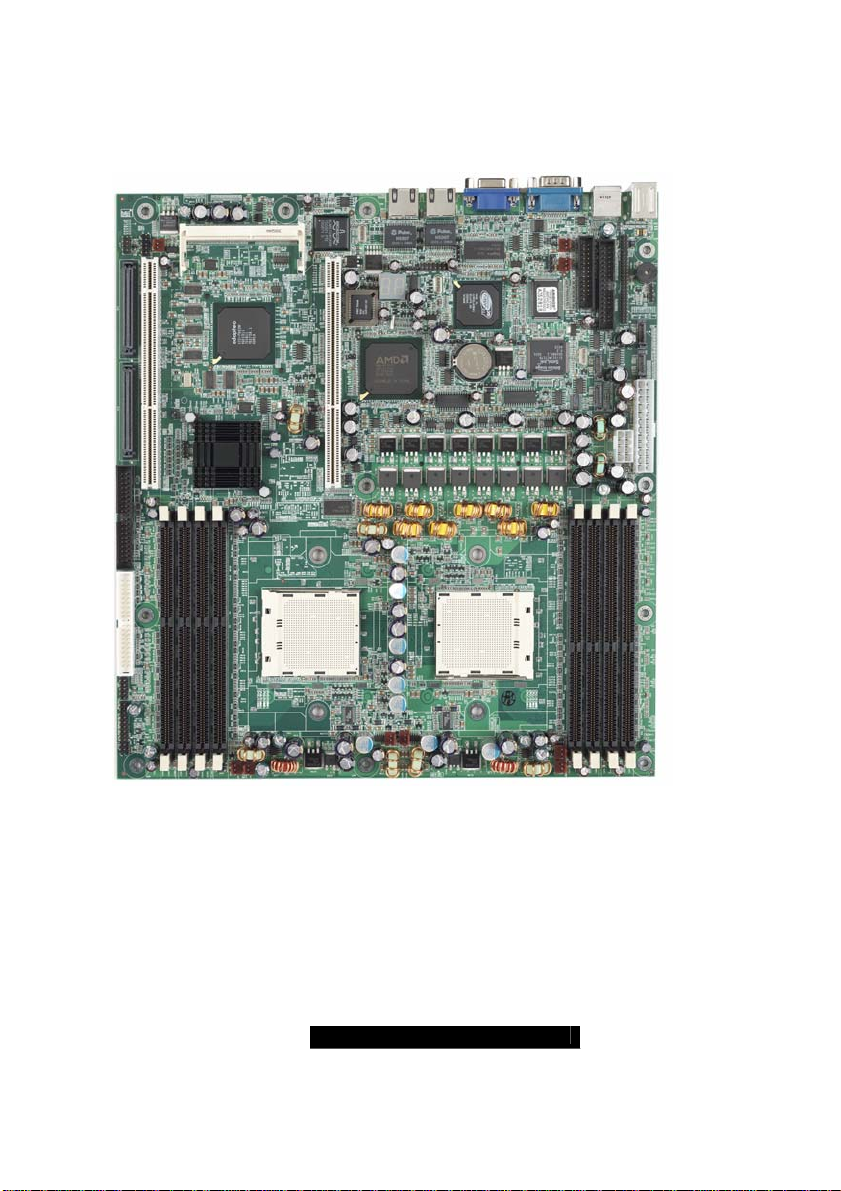
2.00 – Board Image
This picture is representative of the latest board revision available at the
time of publishing. The board you receive may or may not look exactly
like the above picture.
The following page includes details on the vital components of this
motherboard.
8
WWW.TYAN.COM
Page 9
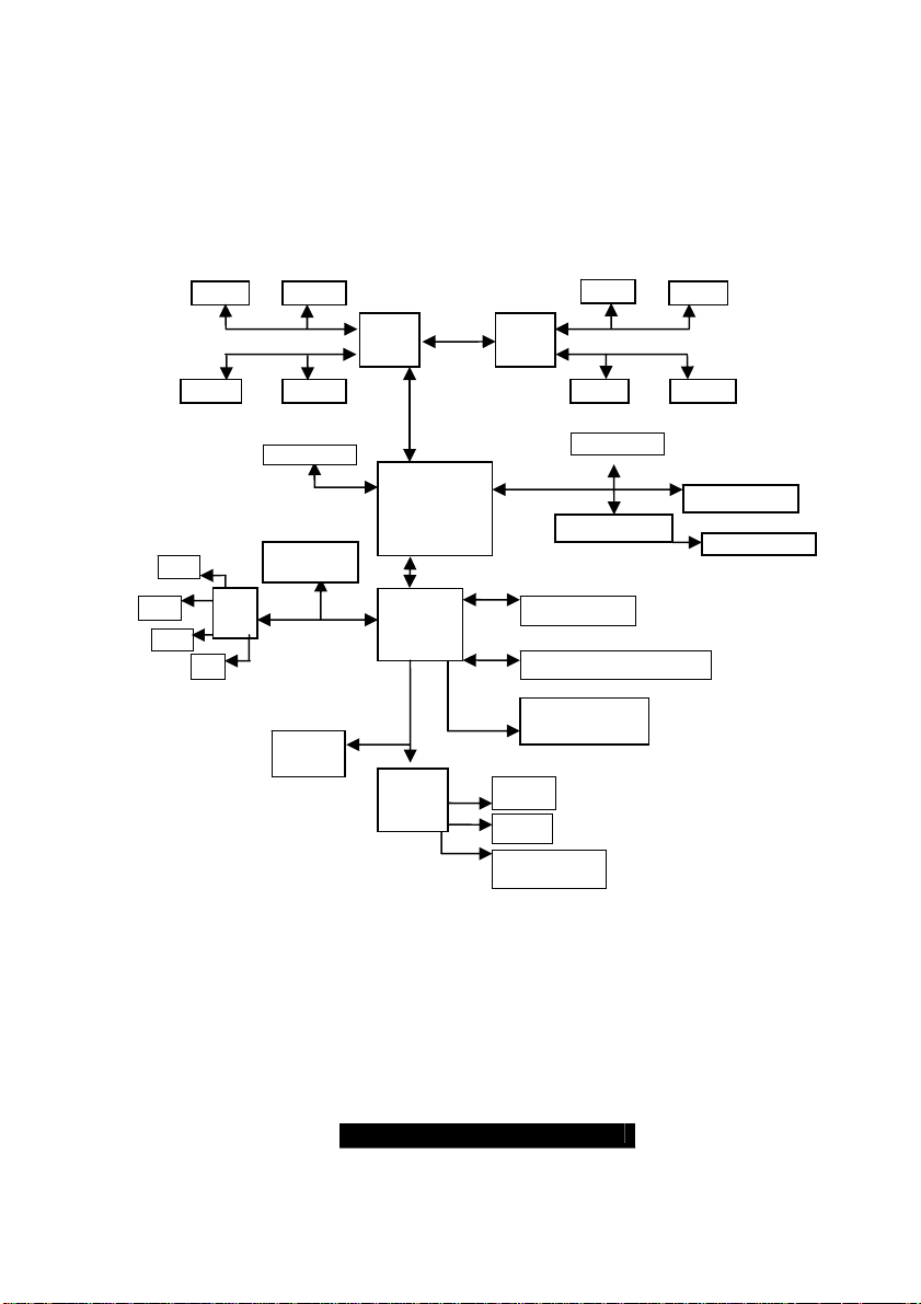
2.01 – Block Diagram
Thunder K8SR (S2881) Block Diagram
Upper 64-bit
Lower 64-bit
1
2
3
DIMM4 DIMM2
128-Bit Dual Channel
PCI-X Slot 1
PCI-X BUS B
ATI RageXL
SATA
3114
4
PCI Bus
32bit/33MHz
BIOS
EEPROM
PCI-X
8131
I/O Hub
8111
LPC BUS
Super
I/O
SMBUS
DIMM2
CPU 2CPU 1
PCI-X BUS A
Floppy
PS/2
Serial & Parallel
128-Bit Dual Channel
DIMM1 DIMM3 DIMM1 DIMM3
PCI-X Slot 2
Adaptec AIC7902
ATA-133 EIDE x2
USB 1.1 front & rear
ADT-7463
Hardware Monitor
DIMM4
Upper 64-bit
Lower 64-bit
Broadcom 5704C
SODIMM ZCR
9
WWW.TYAN.COM
Page 10
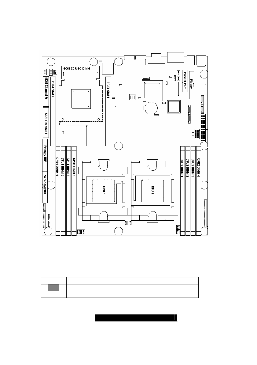
2.02 – Board Parts, Jumpers and Connectors
This diagram is representative of the latest board revision available at the time
of publishing. The board you receive may not look exactly like the above
diagram.
Jumper Legend
OPEN - Jumper OFF without jumper cover
CLOSED - Jumper ON with jumper cover
Key Pin Missing pin to indicate proper orientation
10
WWW.TYAN.COM
Page 11
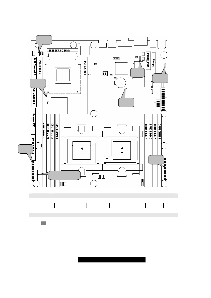
J25
J42
J4
J14
J53
J34
J76
J73 & J75
J4 SMBus 1.1 Connector
Use this connector to connect external SMBUS devices
Pin1: SMB_DATA Pin2: GND Pin3: SMBUS_CLK Pin4: NC
J14 Onboard Buzzer/Speaker header
Close Pin-3 and 4 (Default) - Onboard Buzzer Enabled
Open Pin- 3 and 4 - Disable onboard buzzer or connect to chassis
speaker
11
WWW.TYAN.COM
Page 12
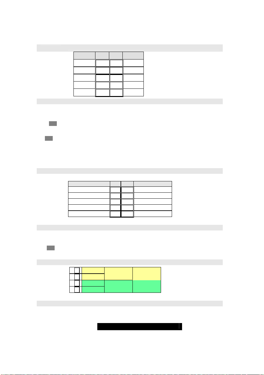
J25
J34 J34 Clear CMOS Jumper
USB Front Panel Header
Signal Pin Pin Signal
VCC
Data Data +
GND
KEY
1 2
3 4
5 6
7 8
9 10
VCC
Data -
Data +
GND
GND
You can reset CMOS settings by using this jumper if you have lost
your system/setup password or need to clear system BIOS setting.
(Clear)
(Default)
There are three easy steps:
Power off system and disconnect both power connectors from
the motherboard
Use jumper cap to close Pin2 and Pin3 for several seconds to Clear
CMOS Put jumper cap back to Pin1 and Pin2 (default setting)
Reconnect power & power on system
NOTE: If you do not disconnect the power connectors from the
motherboard the CMOS may not clear completely.
J42 COM2 Header
Use these pin definitions to connect a port to COM2
Signal Pin Pin Signal
Data Carrier Detect
Receive-Data
Transfer-Data
Data Terminal Ready
Ground
1 2
3 4
5 6
7 8
9 10
Data-Set-Ready
Request-to-Send
Clear-to-Send
Ring-Indicator
NC/KEY
J53 PCI-X Slot 1 Bus Speed Override
Open – (Default) Allows PCI slot 1 to operate at up to 133MHz
(Maximum one PCI-X 133 device)
Closed – Forces PCI slot 1 to operate at a maximum bus speed of
100 MHz
J73/J75 Front Panel LAN LED headers
1
2
3
4
Yellow +
Yellow Green +
Green -
100Mb
LNK/ACT
10Mb
LNK/ACT
Gigabit
LNK/ACT
J76 SMDC HEADER
Tyan proprietary Server Management Daughter Card header
12
WWW.TYAN.COM
Page 13
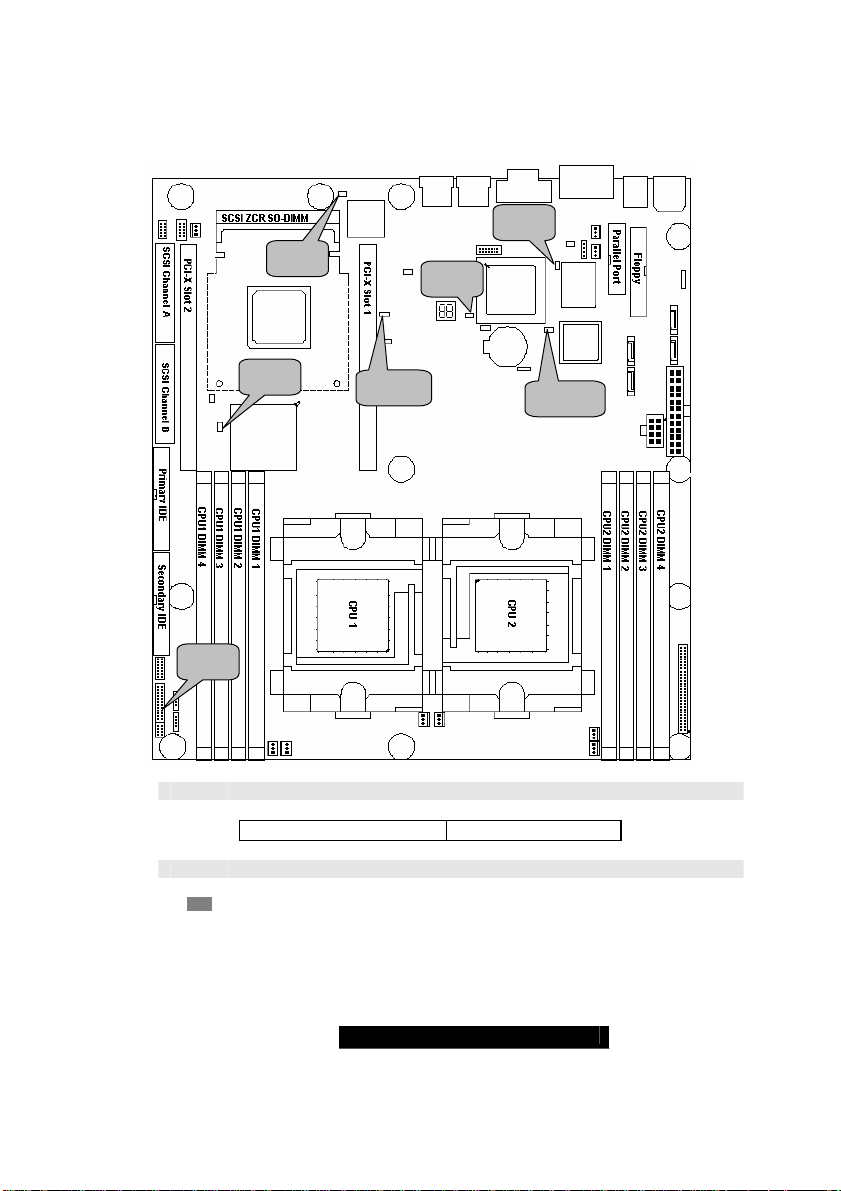
J77
J87
J85
J92
J86
J77 INTR – Chassis Intrusion Header
Active Low this header connects ADT7463 pin76
J85 ATI Video disable
PIN1: Case Open PIN2: GND
Open – (Default) Enable onboard video
Closed – Disable onboard video
J111
13
J102
WWW.TYAN.COM
Page 14
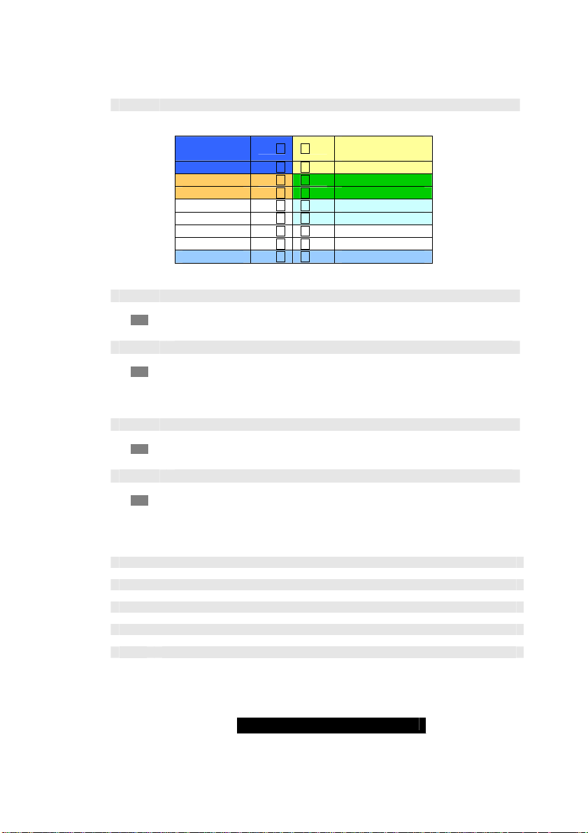
J86 Front Panel Header
HDDLED+
HDDLEDReset SW
Reset SW
+5V
InfraRed Rx
GND
InfraRed Tx
CH INTRU#
1 2
3 4
5 6
7 8
9 10
11 12
13 14
15 16
17 18
PWR LED
(green)
SLP LED (yellow)
PWR SW
PWR SW
SLEEP SW
SLEEP SW
KEY
NC
GND
J87 Gigabit Ethernet Disable
J92 PCI-X Slot 2 Bus Speed Override
Open – (Default) Enable onboard Gigabit Ethernet
Closed – Disable onboard Gigabit Ethernet
Open – (Default) Allows PCI-X slot 2 to operate at up to 100MHz
Closed – Force PCI-X slot 2 to operate in at a maximum 66MHz
Note: This jumper affects integrated Ethernet and SCSI on the
same bus
J102 SATA (Serial ATA) Controller Disable
J111 SCSI Controller Disable (optional)
Open – (Default) Enable onboard SATA Controller
Closed – Disable onboard SATA Controller
Open – (Default) Enable onboard SCSI Controller
Closed – Disable onboard SCSI Controller
OEM Reserved Connectors and Jumpers
DO NOT MODIFY THESE JUMPERS
The pin definition of these headers are not available
J103 RSVD
J104 RSVD
J110 RSVD
J89 GPIO
J90 GPIO
14
WWW.TYAN.COM
Page 15
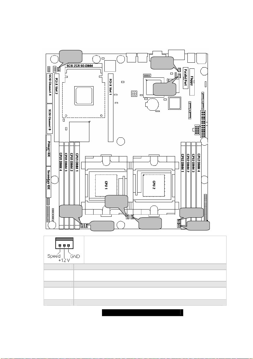
2.03 –Fan Connectors and Hardware Monitoring
FAN7
FAN9
FAN8
FAN4
FAN1 J10
FAN2 J36
FAN3 J37
FAN6
15
FAN3
FAN5
All System fan headers use the same pinout listed on the right
Direct +12V from power supply
(No power control and tachometer monitor)
Fan power control: ADT7463A pin10
Fan tachometer monitor: ADT7463A pin12
FAN2
WWW.TYAN.COM
Page 16
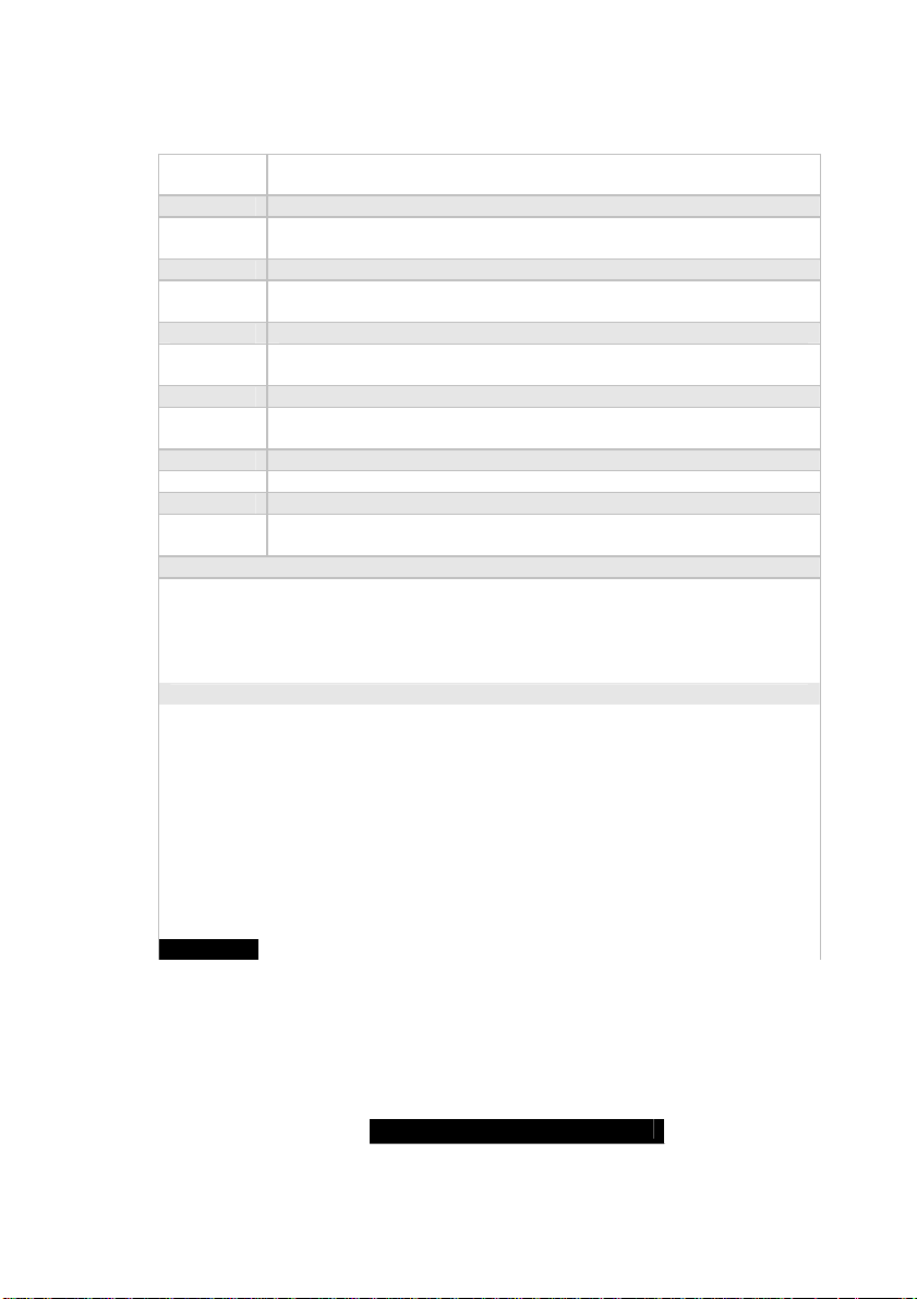
FAN4 J9
FAN5 J11
FAN6 J47
FAN7 J12
FAN8 J38
Fan tachometer monitor: W83627HF/AW pin111
FAN8 J88
CPU 1: ADT7463A pin15 and16 (with processor differential thermal output)
CPU 2: ADT7463A pin17 and 18 (with processor differential thermal output)
CPU1 area: W83627HF/AW pin104 (with R1794 10K thermistor)
CPU2 area: W83627HF/AW pin103 (with R1792 10K thermistor )
CPU VRM area: W83627HF/AW pin102 (with R1793 10K thermistor )
CPU1 Vcore 1.55V W83682HF/F pin100
CPU2 Vcore 1.55V W83682HF/F pin99
CPU1 DDR VTT 1.25V W83682HF/F pin96
CPU2 DDR VTT 1.25V ADT7463A pin23
CPU1 DDR VDD 2.5V W83682HF/F pin95
CPU2 DDR VDD 2.5V ADT7463A pin22
NOTE: ADT7463 SMBus 1.1 slave Address: xx2Dh
Fan power control: W83627HF/AW pin116
Fan tachometer monitor: W83627HF/AW pin113
Fan power control: W83627HF/AW pin115
Fan tachometer monitor: W83627HF/AW pin112
Direct +12V from power supply
(No power control and tachometer monitor)
Fan power control: ADT7463A pin11
Fan tachometer monitor: ADT7463A pin24
Direct +12V from power supply
(No power control and tachometer monitor)
Fan power control: ADT7463A pin13
Fan tachometer monitor: ADT7463A pin9
CPU Temperature Monitoring
Voltage Monitoring
+12V ADT7463A pin21
+5V ADT7463A pin20
3.3V W83682HF/F pin98
+3.3V standby ADT7463A pin4
16
WWW.TYAN.COM
Page 17
2.04 – Installing the Processor(s)
The Thunder K8SR supports the latest 64-bit processor technologies from AMD.
Only AMD Opteron
motherboard.
Check our website for latest processor support. http://www.tyan.com
NOTE
TYAN is not liable for damage as a result of operating an unsupported
configuration.
™
processor 200 series are certified and supported with this
If using a single processor, it MUST be installed in socket CPU0.
When using a single processor only CPU0 memory banks are
addressable.
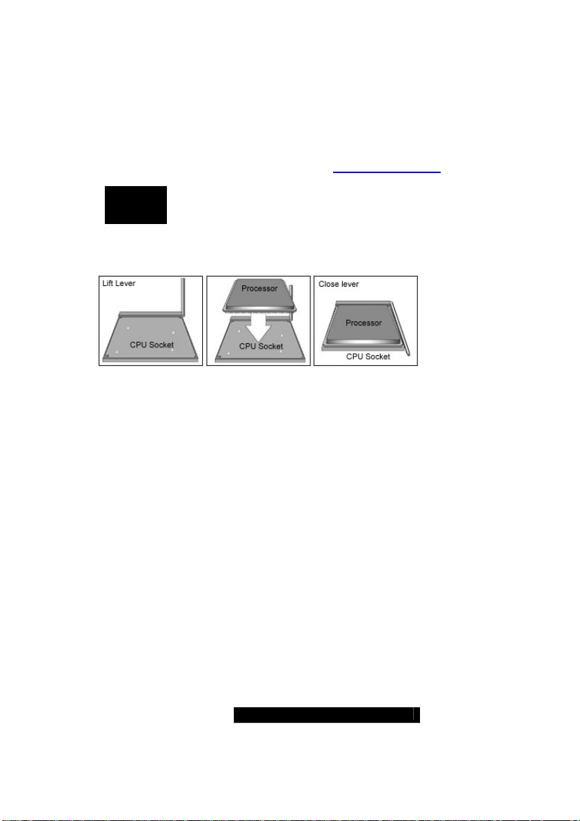
The diagram is provided as a visual guide to help you install socket processors
and may not be an exact representation of the processors you have.
Lift the lever on the socket until it is approximately 90
to the socket.
Align the processor with the socket. There are keyed pins underneath the
processor to ensure that the processor’s installed correctly.
Seat the processor firmly into the socket by gently pressing down until the
processor sits flush with the socket.
Place the socket lever back down until it locks into place.
Your processor is installed.
Repeat these steps for the second processor if you are using two processors.
Take care when installing processors as they have very fragile connector pins
below the processor and can bend and break if inserted improperly.
Heatsink Retention Frame Installation
After you are done installing the processor(s), you should proceed to installing
the retention frame and heatsink. The CPU heatsink will ensure that the
processors do not overheat and continue to operate at maximum performance for
as long as you own them. Overheated processors are also dangerous to the
health of the motherboard.
17
o
or as far back as possible
WWW.TYAN.COM
Page 18
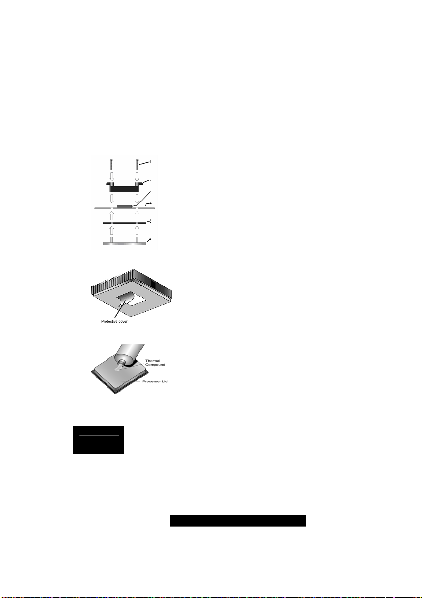
The back-plate assembly prevents excessive motherboard flexing in the area
near the processor and provides a retention bracket for the heatsink.
Because there are many different types of heatsinks available from many
different manufacturers, many have their own method of installation. For the
safest method of installation and information on choosing the appropriate
heatsink, consult the recommended list at www.amd.com
The following diagram will illustrate how to install back-plate and retention frame:
(1) Mounting screws
(2) Retention frame
(3) CPU socket
(4) Motherboard PCB
(5) Adhesive insulator material
(6) Back-plate assembly
NOTE: Please see next section for specific instructions on
how to install mounting bracket.
.
Thermal Interface Material
NOTE
Aways check with AMD and the manufacturer of the heatsink to
ensure the thermal interface material is compatible with the processor
& meets the manufacturer’s warranty requirements
There are two types of thermal interface materials
designed for use with the AMD Opteron processor.
The most common material comes as a small pad
attached to the heatsink at the time of purchase.
There should be a protective cover over the material.
Take care not to touch this material.
Simply remove the protective cover and place the
heatsink on the processor.
The second type of interface material is usually
packaged separately. It is commonly referred to as
‘thermal compound’ or ‘thermal grease’. Apply a thin,
even layer on to the CPU lid (applying too much will
reduce the effectiveness).
18
WWW.TYAN.COM
Page 19
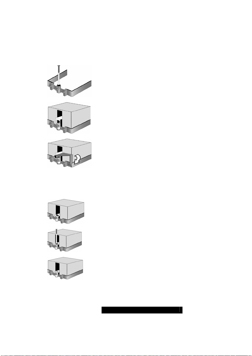
Heatsink Installation Procedures
Type A: CAM LEVER (TYPE) INSTALLATION
1
2
3
Type B: SCREW RETENTION TYPE HEATSINK
1
2
3
1. Once you have completed installing the backplate and interface material; align the retention
bracket screw hole with CPU back-plate standoffs.
Tighten screws to secure retention bracket.
Repeat for on other side.
DO NOT OVERTIGHTEN.
2. After tightening screws secure metal clip to
plastic retention bracket center tab. Repeat for on
other side of heatsink.
3. After securing metal clip to plastic retention
bracket center tab, push down on plastic clip to
lock plastic clip to side tab.
1. Align the heatsink retention frame screw hole with backplate assembly standoffs. Place heatsink inside retention
bracket. Place metal clip over retention frame tab.
2. Insert screw through metal clip. Check that the
heatsink’s metal clip is and the tab on the retention frame
are as illustrated.
3. Tighten screw through metal clip. Repeat on other side.
DO NOT OVER TIGHTEN.
19
WWW.TYAN.COM
Page 20
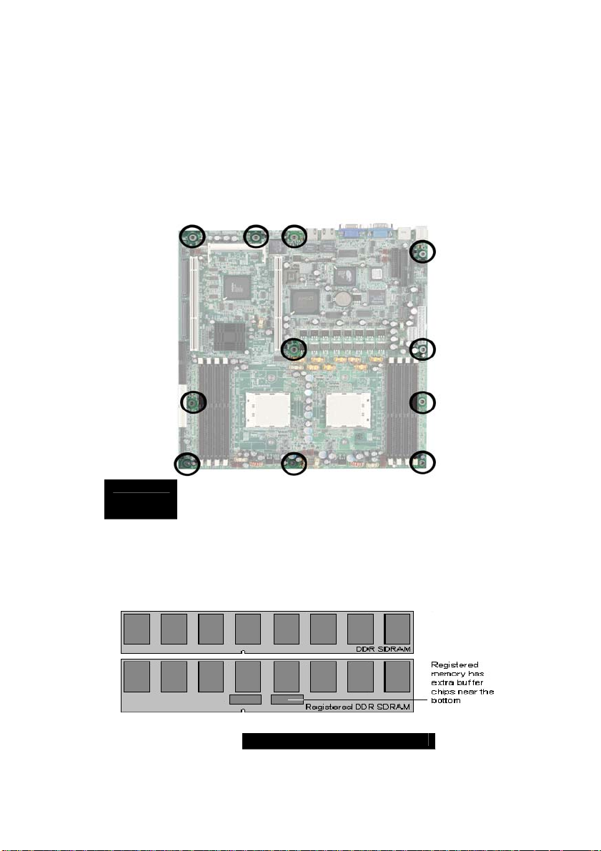
2.05 – Installing Motherboard in Chassis
Before installing your motherboard, make sure your chassis is designed to
support SSI or Extended ATX motherboards. The S2881 has 12 mounting
holes to secure it in the chassis. These mounting holes are highlighted in the
image below. Some rackmount chassis come with preinstalled standoffs.
Check the chassis thoroughly to ensure all standoffs match the mounting
hole pattern.
Be sure to use all of the mounting holes available
NOTE
2.06 – Installing the Memory
Before attempting to install any memory, make sure that the memory you
have is compatible with the motherboard as well as the processor.
The following diagram shows common types of DDR SDRAM modules:
Do not overtighten the screws as this can damage the
motherboard
20
WWW.TYAN.COM
Page 21
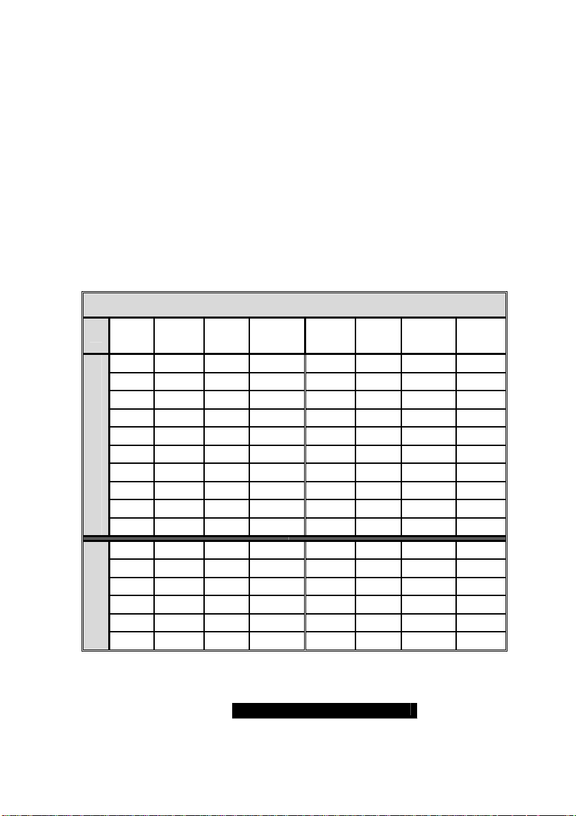
Here are a few key points to note before installing memory into your Thunder
K8SR
• Always install memory beginning with CPU1 DIMM1
• In order to access memory on CPU2; both processors must be installed
• Single, pairs, or four modules are supported on each CPU
• Configure memory symmetrically on each CPU for be st performance
• At least ONE Registered DDR SDRAM module must be i nstalled for the
system to POST (power on self test)
• 128MB, 256MB, 512MB, 1GB, and 2GB* Registered DDR400
#
/333/266
SDRAM memory modules are supported
• The Thunder K8SR supports up to 16GB with two CPU’s installed
*
2GB Registered DDR333/400modules not available at time of print
#
DDR400 supported on Opteron™ 246 and higher
Memory Configuration Chart
(Note: X indicates a populated DIMM Slot)
CPU0
DIMM-A1
128 bit memory support
64 bit memory
support
CPU0
DIMM-A2
X X
X X X X
X X X X
X X X X X X
X X X X X X X X
X X X X
X X
X X X X
X X X X
X X X X
X
X X
X X
X X
X X
X X
CPU0
DIMM-B1
CPU0
DIMM-B2
CPU1
DIMM-A1
CPU1
DIMM-A2
CPU1
DIMM-B1
CPU1
DIMM-B2
Populate both lower and upper 64-bit DIMM slots for 128-bit support
21
WWW.TYAN.COM
Page 22
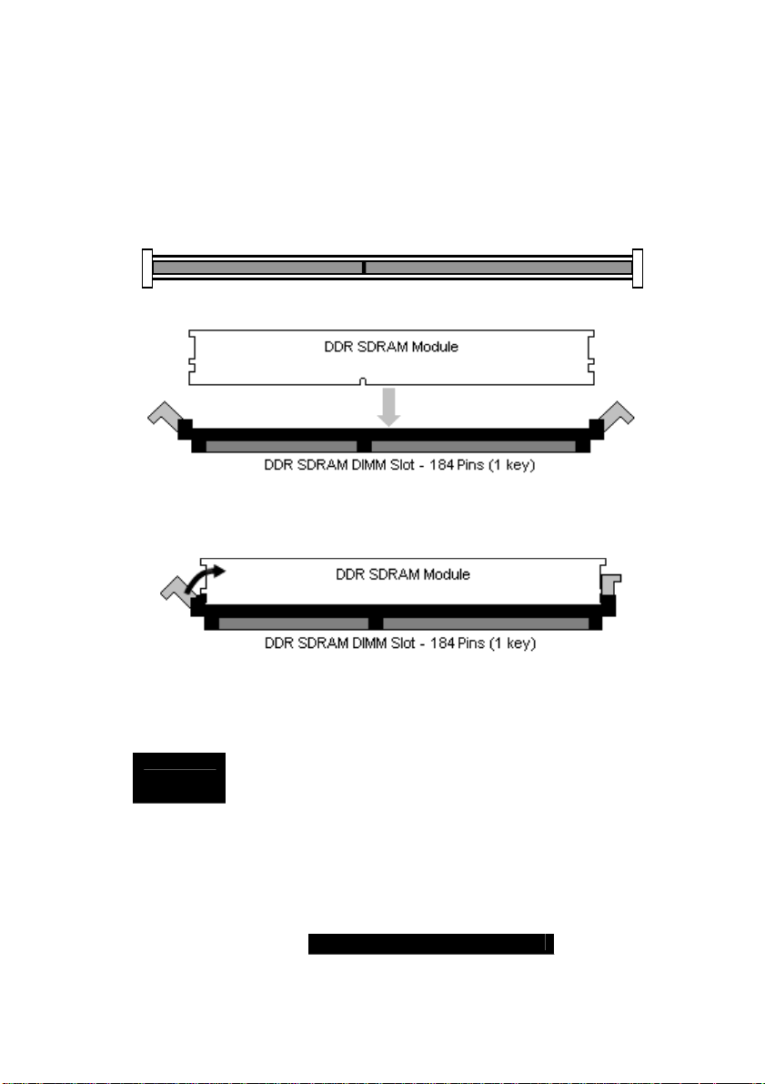
Memory Installation Procedure
)
When you install the memory modules, make sure the module aligns properly
with the memory slot. The modules are keyed to ensure that it is inserted
only one way. The method of installing memory modules are detailed by the
following diagrams.
DDR DIMM Slot 2.5V (TOP VIEW
22
Once the memory modules are firmly seated in the slot, two latches on either
side will close and secure the module into the slot. Sometimes you may need
to close the latches yourself.
To remove the memory module, simply push the latches outwards until the
memory module pops up. Then remove the module.
NOTE
YOU MUST ALWAYS unplug the power connector from the
motherboard before performing system hardware changes.
Otherwise you may damage the board and/or expansion device.
WWW.TYAN.COM
Page 23
2.07 – Attaching Drive Cables
Attaching the IDE drive cable is simple. These cables are “keyed” to only
allow them to be connected in the correct manner. TYAN motherboards have
two on-board IDE channels, each supporting two drives. The black
connector designates the Primary channel, w hile the white connector
designates the Secondary channel.
Simply plug in the BLUE END of the IDE cable into the motherboard IDE
connector, and the other end(s) into the drive(s). Each ATA-133 IDE cable
has three connectors, two of which are closer together. The BLUE connector
that is furthest away from the other two is the end that connects to the
motherboard. The other two connectors are used to connect to drives.
L
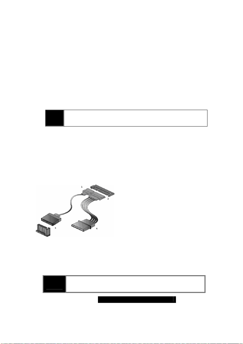
The Thunder K8SR is also equipped with four Serial ATA (SATA)
channels.
There are no Master/Slave jumpers on SATA drives.
Tyan has supplied two SATA cables and one SATA power adapter. If you are
in need of other cables or power adapters please contact your place of
purchase.
The following pictures illustrate how to connect an SATA drive
Floppy Drives
Attaching floppy diskette drives are done in a similar manner to hard drives.
In most cases, there will be a key pin on the cable which will force a proper
connection of the cable. Attach floppy drive (drive A:) to the end of the cable
with the twist in it.
L
Always remember to properly set the drive jumpers
If only using one device on a channel, it should be set as Master
The maximum supported length of an IDE cable is 18”
1.SATA drive cable connection
2.SATA drive power connection
3.SATA cable motherboard
connector
Cable routing is critical in a rackmount environment. The use
of rounded cables is recommended. Always make sure none
of the fans are blocked by drive or power cables.
4.SATA drive power adapter
23
WWW.TYAN.COM
Page 24
2.08 – Installing Add-In Cards
Before installing add-in cards, you should ensure that they are fully
compatible with your motherboard. If in doubt, check the specifications with
the manufacturer.
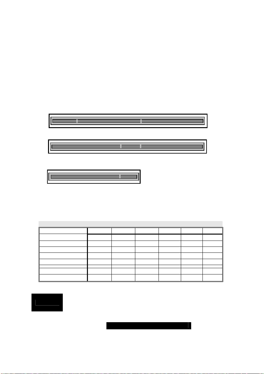
In order to illustrate the most common slots and what they support; we have
provided the illustrations below.
64-bit 3.3v PCI/PCI-X support from 33 to 133MHz
64-bit 5V PCI support from 33 to 66MHz
32-bit 5v Universal PCI supports 33MHZ
Simply find the appropriate slot for your add-in card and insert the card firmly.
Never force any add-in cards into any slots if they do not seat in place. Doing
so will damage the motherboard and void your warranty.
* The AGP slot supports AGPPRO & 1.5v(4x/8x) AGP cards only
PCI Interrupt Routing Table
Slot or Device IDSEL# Bus# INTA INTB INTC INTD
PCI Slot #1 AD19 PCIX-B INTA INTB INTC INTD
PCI Slot #2 AD24 PCIX-A INTD INTA INTB INTC
SODIMM ZCR AD23 PCIX-A INTC
Onboard SCSI AD26 PCIX-A INTA INTB
Onboard GB LAN AD25 PCIX-A INTA INTB
Onboard SATA AD21 PCI Bus0 INTB
Onboard ATI
AD22 PCI Bus0 INTC
aYOU MUST ALWAYS unplug the power connector from the
NOTE
motherboard before performing system hardware changes. Otherwise
you may damage the board and/or expansion device. a
24
WWW.TYAN.COM
Page 25
2.09 – Connecting External Devices
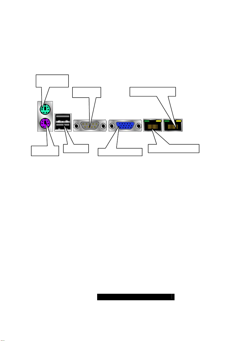
Connecting external devices to the motherboard is an easy task. The
standard devices you should expect to plug into the motherboard are
keyboards, mice, and printer cables. The following diagram will detail the
ATX port stack for the following board:
PS/2 Mouse
Serial Port Gigabit Ethernet
PS/2 KB
USB 1.1 Gigabit Ethernet
Integrated video
25
WWW.TYAN.COM
Page 26
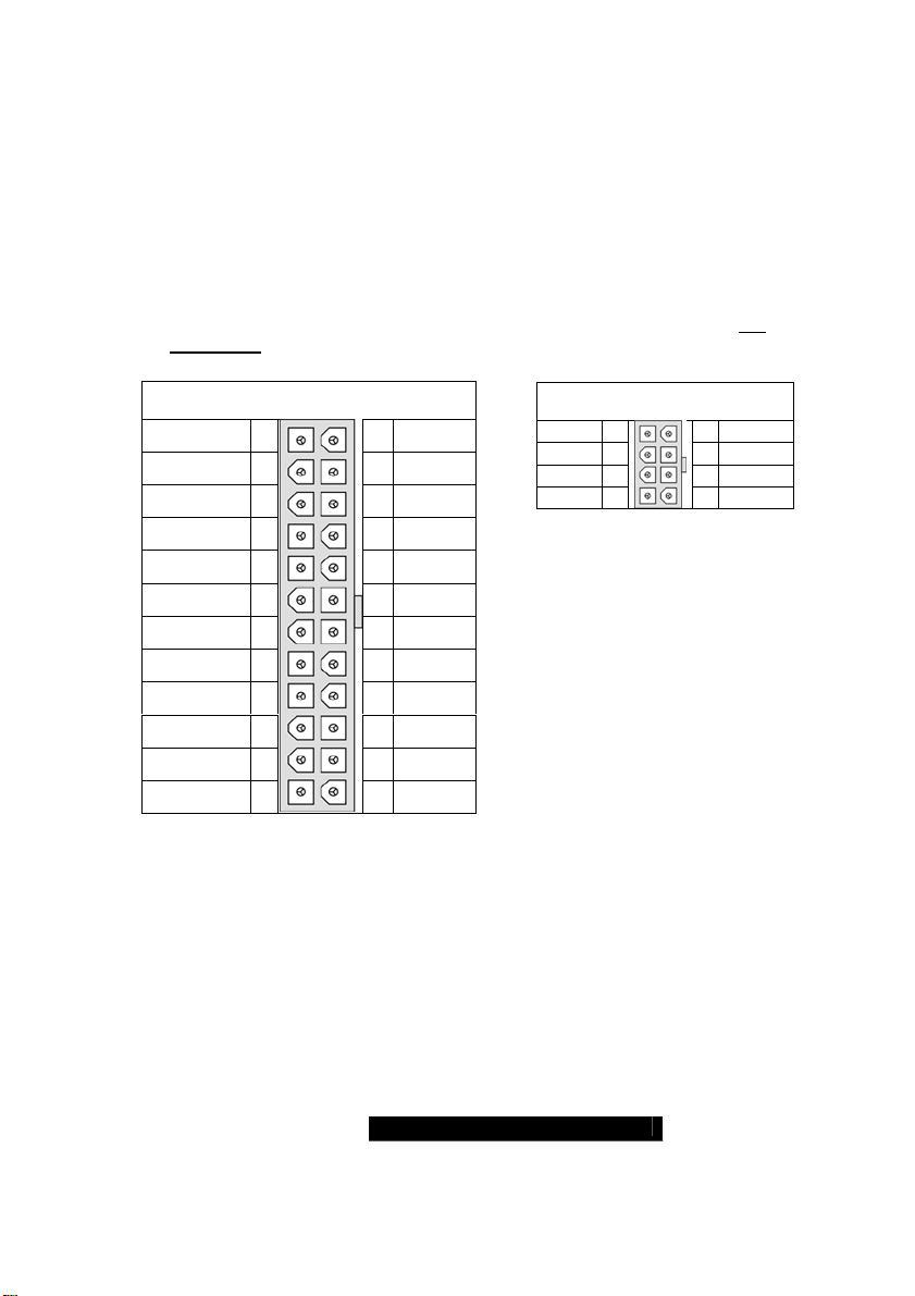
2.10 – Installing the Power Supply
There are two power connectors on your Thunder K8SR.
The Thunder K8SR requires an EPS12V (24-pin + 8-pin) or ATX12V power
supply to boot. EPS12V power supplies are strongly recommended for dual CPU
configurations.
Please be aware that ATX 2.x and ATXGES power supplies are not
compatible with the board and can damage the motherboard and/or CPU(s).
SSI Main Power 24-pin
(Chipset & Components)
+3.3V
+12V2
+12V2
+5VSB
PWR OK
GND
+5V
GND
+5V
GND
+3.3V
+3.3V
12 24
11 23
10 22
9 21
8 20
7 19
6 18
5 17
4 16
3 15
2 14
1 13
GND
+5V
+5V
+5V
RESVD
GND
GND
GND
PSON#
GND
-12v
+3.3V
EPS12V 8-pin
(CPU Power)
GND
GND
GND
GND
48
37
26
1 5
+12V3
+12V3
+12V3
+12V3
Disconnect power supply from electrical outlet
Connect the EPS12V 8-pin power connector
Connect the EPS12V 24-pin power connector
Connect power cable to power supply to power outlet
Make sure you have connected both connectors before attempting to apply
power to the board.
26
WWW.TYAN.COM
Page 27
2.13 – Finishing Up
Congratulations on making it this far! You’re finished setting up the hardware
aspect of your computer. Before closing up your chassis, make sure that all
cables and wires are connected properly, especially IDE cables and most
importantly, jumpers. You may have difficulty powering on your system if the
motherboard jumpers are not set correctly.
In the rare circumstance that you have experienced difficulty, you can find help by
asking your vendor for assistance. If they are not available for assistance, please
find setup information and documentation online at our website or by calling your
vendor’s support line.
WWW.TYAN.COM
27
Page 28
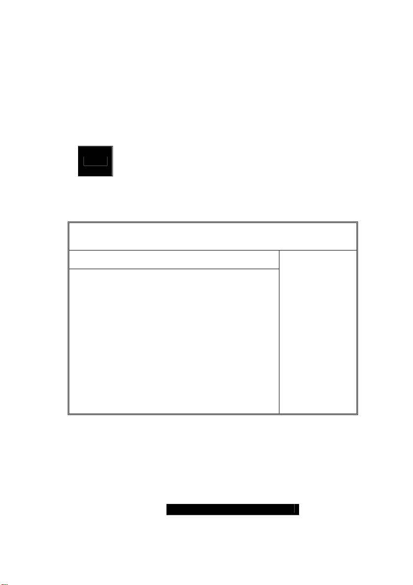
Chapter 3: BIOS
3.00 – BIOS Setup Utility
With the BIOS setup utility, you can modify BIOS settings and control the
special features of your computer. The setup utility uses a number of menus
for making changes and turning the special features on or off.
NOTE
To start the BIOS setup utility:
Main Advanced PCI/PnP Boot Security Chipset Power
System Overview
AMIBIOS
Version : 08.00.xx
Build Date : 08/01/2003
ID : 0ABCF006
Processor
Type : AMD Opteron Model xxx
Speed : xxxx MHz
Count : x
System Memory
Size : xxxx MB
System Time [12:59:59]
System Date [08/01/2003]
To select an item
Use the left/right (Å Æ) arrow keys to make a selection
To display a sub-menu (A pointer “” marks all sub menus)
Use the arrow keys to move the cursor to the sub menu you want. Then press
<Enter>.
BIOS Menu Bar
All menus are based on a typical system. The actual menus
displayed on your screen may be different and depend on the
hardware and features installed in your computer.
a. Turn on or reboot your system
b. Press <Del> during POST (F4 on remote console) to start
BIOS setup utility
BIOS Setup Utility
Exit
28
Use [ENTER],
[TAB] or
[SHIFT_TAB] to
select a field
Use [+] or [-] to
configure system
time.
+/- Change Field
Tab Select Field
F1 Help
F10 Save and
Exit
ESC Exit
WWW.TYAN.COM
Page 29
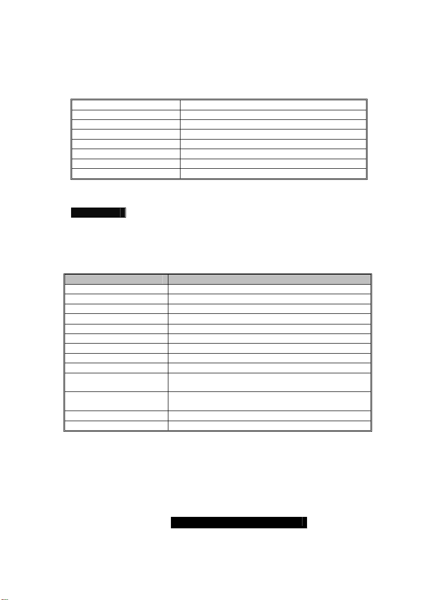
The menu bar at the top of the windows lists these selections:
Main To configure basic system setups
Advanced To configure the advanced chipset features
PCI/PnP To configure legacy Plug & Play or PCI settings
Boot To configure system boot order
Security To configure user and supervisor passwords
Chipset To configure chipset management features
Power To configure power management features
Exit To exit setup utility
NOTE Options written in bold type represent the BIOS setup default
BIOS Legend Bar
The chart describes the legend keys and their alternates:
Key Function
<F1> or <Alt-H> General help window
<ESC> Exit current menu
Å Æ arrow keys Select a different menu
↑ or ↓ arrow keys
<Tab> or <Shift-Tab> Cycle cursor up/down
<Home> or <End> Move cursor to top/bottom of the window
<PgUp> or <PgDn> Move cursor to next/previous page
<F5> or <-> Select the previous value/setting of the field
<F6> or <+> or <Space> Select the next value/setting of the field
<F8> Load Fail Safe default configuration values of the
<F9> Load the Optimal default configuration values of the
<F10> Save and exit
<Enter> Execute command or select submenu
Move cursor up/down
menu
menu
29
WWW.TYAN.COM
Page 30
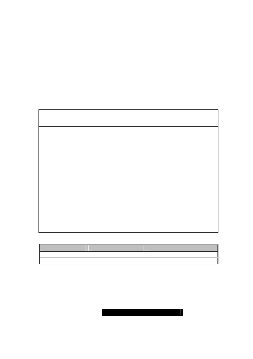
3.01 – BIOS Main Menu
The Main BIOS Menu is the first screen that you can navigate. The Main BIOS
setup menu screen has two main frames. The left frame displays all the options
that can be configured. "Grayed-out" options cannot be configured, options in
blue can be changed.
The right frame displays the key legend. Above the key legend is an area
reserved for a text message. When an option is selected in the left frame, it is
highlighted in white. Often, a text message will accompany it.
BIOS Setup Utility
Main Advanced PCI/PnP Boot Security Chipset Power
System Overview
AMIBIOS
Version : 08.00.xx
Build Date : 4/01/2003
ID : 0ABCF006
Processor
Type : AMD Opteron(tm) Model xxxx
Speed : xxxx MHz
Count : x
System Memory
Exit
Use [ENTER], [TAB] or
[SHIFT_TAB] to select a field
Use [+] or [-] to configure
system time.
+/- Change Field
Tab Select Field
F1 Help
F10 Save and Exit
ESC Exit
Size : xxxx MB
System Time [12:59:59]
System Date [04/01/2003]
Feature Option Description
System Time HH : MM : SS Set the system time
System Date MM : DD : YYYY Set the system date
30
WWW.TYAN.COM
Page 31
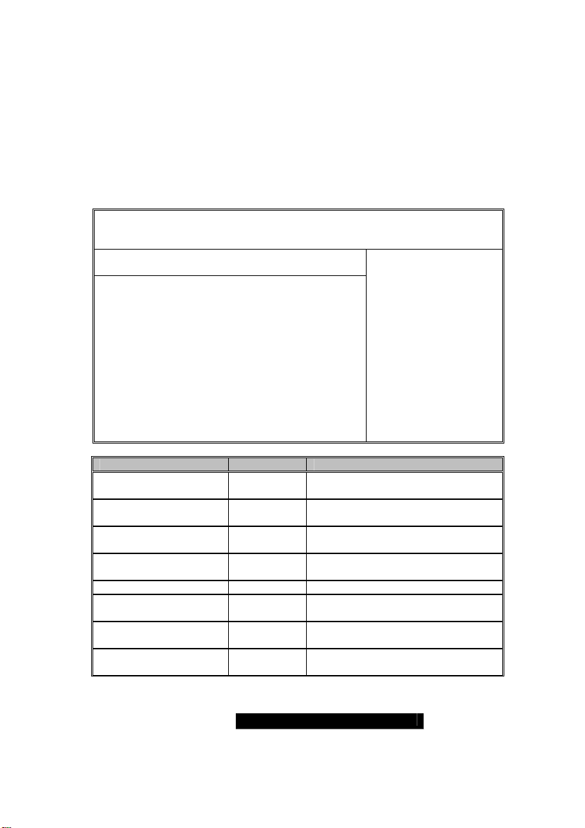
3.02 – BIOS Advanced Menu
You can select any of the items in the left frame of the screen, such as Super
I/O Configuration, to go to the sub menu for that item. You can display an
Advanced BIOS Setup option by highlighting it using the <Arrow> keys. All
Advanced BIOS Setup options are described in this section. The Advanced BIOS
Setup screen is shown below. The sub menus are described on the following
pages.
BIOS Setup Utility
Main Advanced PCI/PnP Boot Security Chipset Power
Advanced Settings
IDE Configuration
Floppy Configuration
Super I/O Configuration
Hardware Health Configuration
Event Log Control
Device & PCI Slots Configuration
Remote Access Configuration
USB Configuration
Exit
Use [ENTER], [TAB] or
[SHIFT_TAB] to select a
field
Use [+] or [-] to
configure system time.
+/- Change Field
Tab Select Field
F1 Help
F10 Save and Exit
ESC Exit
Feature Description
IDE Configuration Menu Item
Floppy Configuration Menu Item
Super I/O Configuration Menu Item
Hardware Health
Configuration
Menu Item
Configures devices connected to
AMD8111 IDE controller
Configures devices connected to the
floppy controller
Configures devices connected to the
Super I/O Configuration
Configures & views Hardware
Monitor
Event Log Control Menu Item Views & controls Event Log
Device & PCI Slots
Configuration
Remote Access
Configuration
Menu Item
Menu Item Configures Console Redirect
USB Configuration Menu Item
Allows control of integrated devices
& cards plugged into PCI slots
Configures USB controller & legacy
device support
31
WWW.TYAN.COM
Page 32
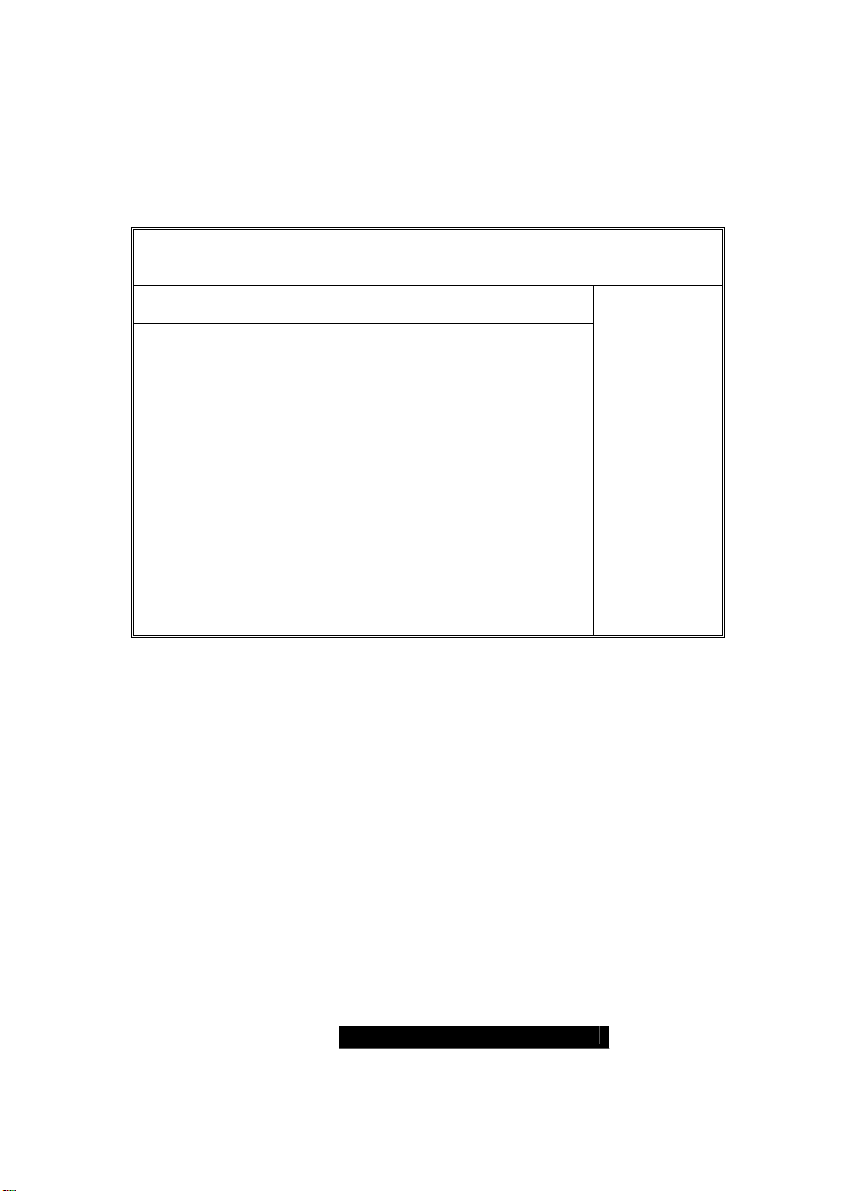
IDE Configuration Sub-Menu
You can use this screen to select options for the IDE Configuration Settings.
Use the up and down <Arrow> keys to select an item. Use the <Plus> and
<Minus> keys to change the value of the selected option.
BIOS Setup Utility
Main Advanced PCI/PnP Boot Security Chipset Power
IDE Configuration
Onboard PCI IDE Controller [Both]
Primary IDE Master [xxxx]
Primary IDE Slave [xxxx]
Secondary IDE Master [xxxx]
Secondary IDE Slave [xxxx]
Hard Disk Write Protect [Disable]
IDE Detect Time Out (Sec) [xx]
ATA(PI) 80Pin Cable Detection [Host & Device]
Exit
Use [ENTER],
[TAB] or
[SHIFT_TAB]
to select a field
Use [+] or [-] to
configure
system time.
+/- Change
Field
Tab Select
Field
F1 Help
F10 Save and
Exit
ESC Exit
32
WWW.TYAN.COM
 Loading...