

Page 1

TM
Thunder i860
S2603
User’s Manual
Revision 1.00
Copyright © Tyan Computer Corporation, 2001. All rights reserved. No part of this
manual may be reproduced or translated without prior written consent from Tyan
Computer Corp.
All registered and unregistered trademarks and company names contained in this
manual are property of their respective owners including, but not limited to the following.
Tyan, Thunder i860 S2603 are trademarks of Tyan Computer Corporation.
Intel, Xeon, 860 chipset are trademarks of Intel Corporation.
Rambus is a trademark of Rambus Inc.
Phoenix, Phoenix BIOS are trademarks of Phoenix Software.
Microsoft, Windows are trademarks of Microsoft Corporation.
IBM, PC, AT, PS/2 are trademarks of IBM Corporation.
QLogic, Zircon are trademarks of QLogic Corporation.
Winbond is a trademark of Winbond Electronics Corporation.
National is a trademark of National Semiconductor Corporation.
Information contained in this document is furnished by Tyan Computer Corporation and has been reviewed for accuracy and reliability prior to printing. Tyan
assumes no liability whatsoever, and disclaims any express or implied warranty,
relating to sale and/or use of Tyan products including liability or warranties relating
to fitness for a part icula r purpose o r me rchan tabili ty. T yan retain s the ri ght to m ake
changes to product descriptions and/or specifications at any time, without notice.
In no event will Tyan be held liable for any direct or indirect, incidental or consequential damage, loss of use, loss of data or other malady resulting from errors or
inaccuracies of information contained in this document.
Page 2

Table of Contents
Chapter 1: Introduction
Overview ....................................................................................................................4
1.1
Hardware Specifications ............................................................................................5
1.2
Software Specifications ..............................................................................................6
1.3
Technical Support ......................................................................................................7
1.4
Returning Merchandise for Service ............................................................................7
1.5
.............................................................
Chapter 2: Board Installation
2.1
Unpacking ..................................................................................................................8
2.2
Installation ..................................................................................................................8
2.3
How to install our products right... the first time ..........................................................8
2.4
Quick Reference for Jumpers ..................................................................................10
2.5
Map of Motherboard Jumpers ..................................................................................11
2.6
Setting up Jumpers and Onboard Connectors .........................................................12
2.6-A
Front Panel Connector .............................................................................................12
2.6-B
CMOS Reset ............................................................................................................12
2.6-C
BIOS Boot Block ......................................................................................................13
2.6-D
DIP Switch ...............................................................................................................13
2.6-E
Onboard LAN Enable/Disable ..................................................................................14
2.6-F
Onboard SCSI Enable/Disable .................................................................................14
2.6-G
Speaker Connector ........... ...... ............................................................... ..... ..... ..... ...15
2.6-H
PCI Speed Select .....................................................................................................15
2.6-I
FAN Connectors .................................... ...... ..... ..... ..... .............................................16
2.6-J
Soft Power Connector ..............................................................................................16
2.6-K
Hardware Reset Switch Connector Installation ........................................................16
2.6-L
Flash Utility ............................. ..... ..... ..... ...... ..... .......................................................16
2.7
Mounting the Motherboard in the Chassis ................................................................17
2.8
Installing Memory .....................................................................................................18
2.9
Installing the CPU and Cooling Fan(s) .....................................................................23
2.10
Connecting IDE and Floppy Drives ..........................................................................25
2.11
Installing Add-on Cards ............................................................................................27
About the AGP Pro slot ............................................................................................28
2.12
Connecting PS/2, USB, and Serial Devices .............................................................29
2.13
Connecting the Power Supply ..................................................................................30
2.14
Frequently Asked Questions (FAQ) .........................................................................32
Page 4
.............................................................
8
Chapter 3: BIOS Setup
Introduction to the BIOS Setup .................................................................................33
Starting Setup ................... ...... ..... ..... ..... ............................................................... ...33
Setup Keys ...............................................................................................................34
Getting Help .............................................................................................................34
In Case of Problems .................................................................................................34
Setup Variations .......................................................................................................34
2
....................................................................
http://www.tyan.com
33
Page 3

Main Setup ........................ ...... ..... ..... ..... ...... ............................................................353.1
Advanced Setup .......................................................................................................363.2
3.2-A
Processors screen ..................................................................................................36
3.2-B
Chipset screen .........................................................................................................37
3.2-C
Floppy Disk Drive screen .........................................................................................37
3.2-D
IDE Devices screen ..................................................................................................38
3.2-E
Integrated SCSI screen ............................................................................................40
3.2-F
Integrated Network screen ........... ..... ..... ...... ..... ..... ..................................................40
3.2-G
Integrated I/O Ports screen ......................................................................................41
3.2-H
Integrated Audio screen ...........................................................................................42
3.2-I
AGP Slot (Graphics) screen .....................................................................................42
3.2-J
PCI Device, Slot #1 (...2, 3, 4, 5) screen ..................................................................43
3.3
Security Setup ..........................................................................................................43
3.4
Power Setup ............................................................................................................45
3.5
Boot Setup ...............................................................................................................45
3.6
Exit Setup .................................................................................................................46
Chapter 4: System Resources
Beep Codes .............................................................................................................47
4.1
Flash Utility ............................. ..... ..... ..... ...... ..... .......................................................47
4.2
.......................................................
Appendix I: SCSI Installation and LAN Information 48......................
Introduction ..............................................................................................................48
Features of the LSI Symbios SCSI BIOS .................................................................48
Legacy Support for non-Ultra160 SCSI devices .......................................................48
Setting up internal SCSI peripherals ........................................................................48
Checking SCSI IDs ..................................................................................................48
Terminating SCSI devices ........................................................................................48
Connecting SCSI Peripherals ..................................................................................48
Connecting internal cables for Ultra160 LVD SCSI devices .....................................48
Information on the LSI Symbios 53C1010 SCSI BIOS .............................................50
Boot Initialization with BIOS Boot Specification (BBS) .............................................50
CD-ROM Boot Initialization ......................................................................................50
Starting the SCSI BIOS Configuration Utility ............................................................50
Error Messages ........................................................................................................51
Using the Configuration Utility ..................................................................................51
Main Menu ...............................................................................................................52
Boot Adapter List ......................................................................................................53
Global Properties .....................................................................................................54
Adapter Properties ....... ..... ...... ..... ..... ..... ................................ ..... ..... ...... ..... ..... ..... ...55
Device Properties .....................................................................................................57
Quitting the SCSI BIOS Configuration Utility ............................................................58
LAN Information .......................................................................................................59
Appendix II: Glossary
47
60.......................................................................
Thunder i860 S2603
3
Page 4

Chapter 1: Introduction
1.1 Congratulations!
You are now the proud owner of the premier dual Intel® Xeon™ platform!
The Thunder i860™ is a high performance workstation platform designed for applications that require the
power of dual Intel® Xeon™ processors. This platform utilizes the Intel 860 chipset and can support CPU
speeds through 1.7+GHz* and front side bus speeds of 100 MHz or 133 MHz. Please see Tyan’s website
for updates and information concerning CPU information and support:
http://www.tyan.com
This integrated performance boar d is supported i n an Extend ed ATX form factor. Some of the feat ures
included are onboard UltraDMA-100/66/33 support, and an Intel 82550 10/100 LAN controller.
With I/O and drive controller support onboard, the one 4X AGP Pro 50 slot, three 32-bit/33MHz PCI slots,
and two 64/32-bit 66/33MHz PCI slots are free for numerous types of add-on expansion cards. The use of
a separate Memory Expansion Card (MEC) allows for memory expansion options.
Remember to visit Tyan’s website at http://www.tyan.com. T here you can find information on all of
Tyan’s products with FAQs, distributors list, and BIOS settings explanations.
NOTE: Due to its extremely pow er fu l pr oc ess in g cap ab ili tie s, th e Th unde r i8 60 re qu ires a spec ialized dual Xeon-capable, AP PROVED* power supply. Also, a Memory Expansion Card (MEC) is
required to harness the complete Rambus memory performance potential.
* not verified at time of print, check the Tyan website for updates: http://www.tyan.com
4
http://www.tyan.com
Page 5

1.2 Hardware Specifications
Processor Information
Expansion Slots
Chipset Information
Hardware Monit oring
Memory
Integrated I/O
Integrated PCI IDE
Dual PGA603 ZIF sockets
Supports dual Intel Xeon processors
One onboard VRM
400MHz system bus support
One 4X AGP Pro 50 slot supports 2x/4x modes
Three 32-bit 33MHz PCI slots
Two 64/32-bit 66/33MHz 3.3V PCI slots
Total of six usable slots
Intel 860 chipset
MCH+ICH2+FWH
National PC87366 Super I/O ASIC
Winbond 83782D hardware monitoring chip
3-pin fan monitoring headers
CPU temperature and voltage monitoring
Eight 168-pin Rambus RIMM sockets (on MEC)
Supports up to 2GB* PC800 Registered RDRAM
Supports ECC (72-bit) memory modules
One floppy connector supports up to two drives
Two 9-pin 16550-based serial ports
One 25-pin SPP/ECP/EPP parallel port
Two USB ports
PS/2 keyboard and mouse ports
Dual-channel master mode
Up to four Enhanced IDE devices
Support for UltraDMA-100/66/33 IDE and ATAPI compliant devices
Integrated LAN
Integrated SCSI
(manufacturing option)
Integrated Audio
(manufacturing option)
* Not validated at time of print, please check Tyan website for memory compatibility information:
http://www.tyan.com
Intel 82550 LAN controller
10/100 Mbps data transfer rate capability
LSI Symbios 53C1010R controller
Dual-channel Ultra160 SCSI support
160Mbps maximum data throug hpu t
Supports up to 15 LVD SCSI devices per channel
Channels 1 & 2: 68-pin connector each
AD1885 chipset
AC’97 codec
Line-in, line-out, and mic-in ports
Thunder i860 S2603
5
Page 6

BIOS
Phoenix BIO S 2 Mbit Flash
Supports APM 1.2 & ACPI 1.0
Auto-configuration of IDE hard disk types
Multiple boot options
DMI 2.0 compliant
Form Factor
Regulatory
1.3 Software Specifications
OS
Ext. ATX 12” x 13” (304.80mm x 330.20mm)
One 24-pin and one 8-pin power connector
Stacked mouse & keyboard ports
Stacked two USB ports
Stacked one parallel and two serial ports
One RJ-45 LAN port with LEDs
FCC Class B (Declaration of Conformity)
European Community CE (Declaration of Conformity)
Windows NT/2000
6
http://www.tyan.com
Page 7

1.4 Technical Support
If a problem arises with your system , you should turn to your dealer for he lp first. Your system has most
likely been configure d by t hem, a nd the y should have the best ide a of wh at har dware and so ftwa re your
system contains. Hence, they shou ld be of the mo st assist anc e. F urt her more, if you p urch ase d you r system from a dealer near you, you can actual ly bring your system t o them to have it service d, instead of
attempting to do so yourself (which can have expensive consequences).
Help Resources:
1. See the FAQ and beep codes section of this manual.
2. See the Tyan website for FAQ, bulletins, driver updates, and other
information: http://www.tyan.com
3. Contact your dealer for help BEFORE calling Tyan.
4. Check the Tyan user group: alt.comp.periphs.mainboard.tyan
1.5 Returning Merchandise for Service
During the warranty pe riod, contact your d istributor or system ve ndor FIRST for any product prob lems.
This warranty only covers no rm al cust ome r use and does n ot cove r da mag es i ncu rr ed du ring shipp i ng or
failure due to the alteration, misuse, abuse, or improper maintenance of products.
NOTE: A receipt or cop y of your invo ice ma rked with t he da te of pur chas e is re quir ed be fore any
warranty service can be rendered. You may obtain service by calling the manufacturer for a
Return Merchandis e Authorization (RM A) number. The RMA number should be prominently displayed on the outsid e of the sh ipp in g ca rt on an d th e p ack ag e sh ou ld be m ail ed pr ep aid . Tyan will
pay to have the board shipped back to you.
Thunder i860 S2603
7
Page 8

Chapter 2: Board Installation
2.1 Unpacking
The retail motherboard package should contain the following:
Thunder i860 motherboard
Memory Expansion Card (MEC)
(2) Continuity RIMMs
34-pin floppy cable
UltraDMA-100/66/33 IDE cable
68-pin Ultra160 LVD SCSI cable
I/O shield*
Thunder i860 user’s manual
Tyan driver CD
(2) LSI SYM1010 SCSI Driver Disks
2.2 Installation
You are now ready to install your motherboard. T he mounting hole pattern of the mo therboard ma tches
the ATX board specifications, so your chassis must b e capable of supporting an Extend ed ATX board
(check the motherboard dimensions provided on p. 6).
2.3 How to install our products right.. the first time.
Question: what’s the first thing I should do?
The first thing you should do is read the user’s manual. It contains important information which will m ake
configuration and setup much easier, as well as provide information on device installation and component
set up. By reading through the manual completely befo re installing your motherboard, you will have a
complete overview on the installation.
* if you require a different I/O shield solution, please contact your chassis vendor
8
http://www.tyan.com
Page 9

Here are some safety tips:
(1) Ground yourself properly before removing your motherboard from the antistatic bag. Unplug
the power from your computer power supply and touch any metal part on the computer case. (You
might also want to wear a grounded wrist strap.)
(2) Hold the motherboard by its edges and do not touch the bottom of the board.
(3) Avoid touching motherboard components, IC chips, connectors, and leads.
(4) Avoid touching pins of memory modules and chips.
(5) Place motherboard on a grounded antistatic surface or on the antistatic bag.
Having reviewed the precautions above, the next step is to take the motherboard out of the cardboard box
and static bag, hold it by its edges, and pl ace it on a grounded a ntistatic surface, com ponent side up.
Inspect the board for damage.
NOTE: DO NOT APPLY POWER T O THE BOARD IF IT HAS BEEN DAMAGED!
Press down on any of the socketed ICs if it appears that they are not properly seated (the board should
still be on an antistatic mat). Do not touch the bottom of the board. Remember, don’t take any electronic
device out of its protective bag until you are ready to actually install it into the computer case. If you do not
ground yourself, you risk zapping the motherboard or adapter card. Subsequent problems may not arise
immediately because electrostatic discharge, unlike physical damage, causes the device to fail over time.
Thunder i860 S2603
9
Page 10
2.4 Quick References for Jumpers
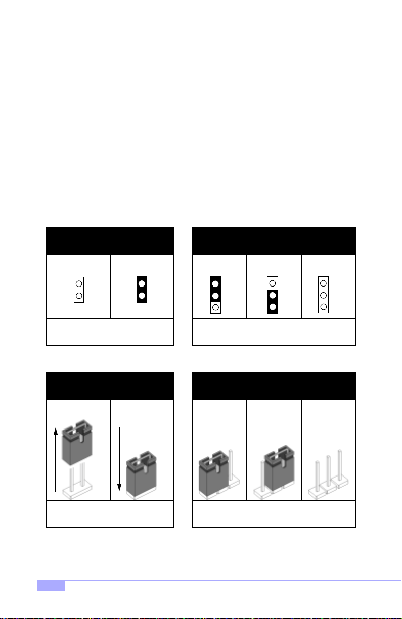
In this manual, the term “close d” and “on” are used wh en referring to jumpers (or jumper pins) that are
active; “open” and “off” a re u s ed whe n re fer ring to j u mp ers (or j um per pin s) that are inactive. See Figure
2.0a and Figure 2.0c for examples of “on” and “off” pins and jumpers.
Jumpers and pins are connec ted by slipping the plastic jum per connector over the top of tw o adjacent
jumper pins (indica ted b y 1-2 or 2-3 ). Th e met al r od insid e the plast ic shell bridg es the gap b etween the
two pins, completing the circ uit. See Figure 2.0b and Figure 2.0d for more examples of 3-pin jumper
connections. NOTE: The small number “1” indicates pin 1.
The tables and maps on the following pages will help you set the jumpers for CPU speed, infrared, and
external connector pin assignments, among others. The miniature motherboard maps will help you locate
the jumpers on your board. Full page maps of the motherboard can be found on the next two pages.
2-pin jumpers
off on
Figure 2.0a
(overhead view)
1-2 2-3 open
3-pin jumpers
1
2
3
Figure 2. 0b
(overhead view)
2-pin jumpers 3-pin jumpers
1-2 2-3 openoff on
11
Figure 2. 0c
(front angle view)
Figure 2. 0d
(front angle view)
1
2
3
1
2
3
10
http://www.tyan.com
Page 11
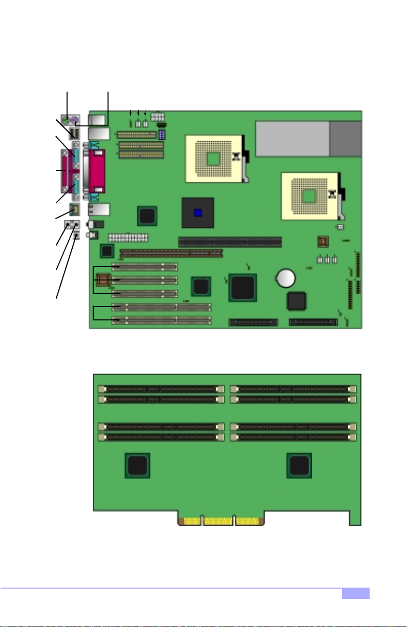
2.5 Map of Motherboard Jumpers
Mouse port
(upper port)
USB
Ports
Serial
port 1
port
Parallel
Serial
port 2
port
LAN
Line-in*Line-out*Mic-in*
(2) 64/32-bit
Keyboard port
(lower port)
Intel
82550
(3) 32-bit
PCI slots
PCI slots
66/33MHz
FDD
24-pin power
J43
Connector
connector
J28
J59
J34
8-pin power
connector
J33
AUD CD
J26**
JBC2
JBC1
Processor 1 (P1)
Intel
i860
AGP Pro 4X Slot
J25
MEC Slot
J51
53C1010R
LSI
SCSI*
J50
Processor 0 (P0)
Battery
SCSI CH. 1*SCSI CH. 2*
J13
J32
J20
J37
J12
ITP
J49
J24
J23
J36*
J35
Memory Expansion Card (MEC)
* indicates an optional feature available on some Thunder i860 models
** J26 (dip switch), if present on the Thunder i860, must always have positions 1 through 4 switched to
“OFF” (in the bottom position). Details on p.13.
Thunder i860 S2603
11
Page 12
2.6 Setting up Jumpers and Onboard Connectors
Pinouts for certain connectors are available on the Tyan website: http://www.tyan.com
Pinouts for certain connectors are available on the Tyan website: http://www.tyan.com
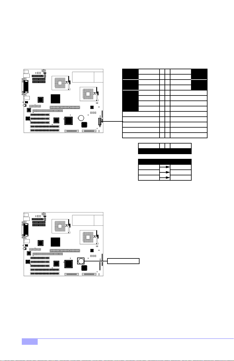
A. Front Panel Connector (J24)
VCC
12
LED
HDD
Sw
Rst
Infrared
LED
ground
switch 7 8
IR +5V
IR RX
ground
IR TX
5346
9
13
151716
1920
2122
2324
2526
Pwr LED+
Slp LED+
switch
ground
10
121411
18
Pwr
LED
Sw
Pwr
Your chassis will usually come with connectors to install onto
the motherboard, such as HDD and Power LEDs. The Front
Panel Connector has been implemented for such purposes.
B. CMOS Reset (Battery)
CMOS Battery
If you have been lo cked out of your system because you forgot your password or set the CMOS incorrectly, or have just finished flashing your BIOS follow the instructions below.
1. Power off the system, and disconnect the power supply
2. Pop out (uninstall) the battery by pressing on the rear latch
3. Wait about FIVE seconds
4. Re-install the battery, then power on the system again
By following this procedure, you will erase your password and reset the CMOS.
LAN LED
Abbreviations
Pwr Power
Slp Sleep
LEDVCC 27 28
ResetRst
12
http://www.tyan.com
Page 13
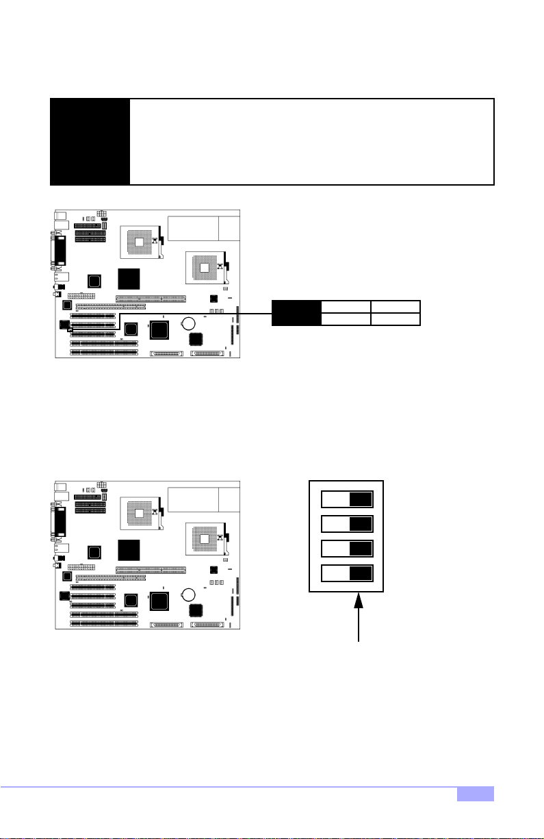
C. BIOS Boot Block (J43)
In case there is an error during flashing, the BIOS Boot Block provides a protection feature for the BIOS.
DO NOT alter this jumper unless you are absolutely sure you fully understand this
jumper’s effects on your system.
NOTE:
Tyan takes no reponsibility and will not be held liable for damage related to alteration of this jumper from its factory-set default. Default is OPEN.
J43
D. DIP Switch (J26) (optional)
This is a DIP switch for internal purposes. If present on the Thunder i860, please make sure that ALL
switches must always have positions 1 through 4 switched to “OFF” (in the bottom position).
open
unprotect
* default is OPEN
ON
All switches are in the
OFF position
close
protect
1 2 3 4
Thunder i860 S2603
13
Page 14
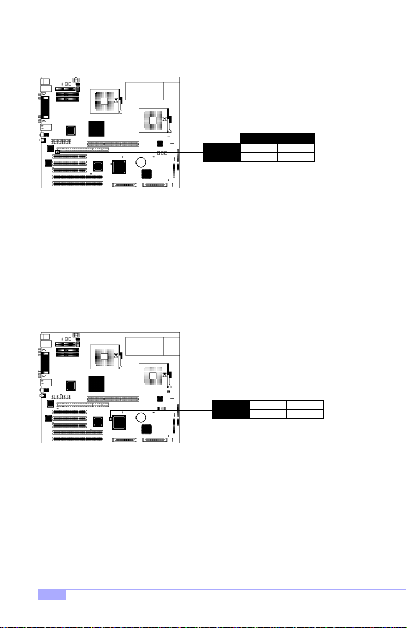
E. Onboard LAN Enable/Disable (J28)
This jumper can disable the onboard LAN port.
LAN
J28
F. Onboard SCSI Enable/Disable (J51)
This jumper can disable the on boa rd SCS I por ts. P leas e note t hat both SC SI por ts w ill be disab le d at the
same time.
close
disable
* default is OPEN
open
enable
14
J51
close
disable
* default is OPEN
open
enable
http://www.tyan.com
Page 15

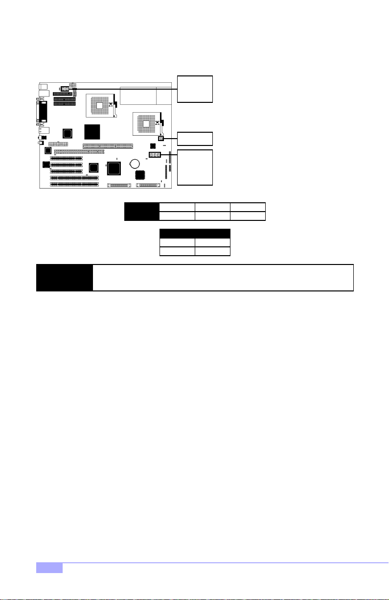
G. Speaker Connector (J23)
This is the 4-pin connector for a speaker.
J23
H. PCI Speed Select (J25)
This connector controls the speed of the 64-bit PCI slots.
1
power in2no connect3no connect4speaker
J25
open
66 MHz
close
33 MHz
Tyan takes no responsibility and will not be held liable for damage related to the
NOTE:
alteration of J25 from the correct setting corresponding to your PCI card manufacturer’s designated operating speed.
Thunder i860 S2603
* default is OPEN
15
Page 16
I. FAN Connectors (FAN)
These are the 3-pin connectors for both CPU and chassis fans.
J34
J33
J32
J36*
J35
J37
FAN
NOTE:
J. Soft Power Connector
The soft power connector is part of jumper block J24 (pins 6 and 8). This board uses the chipset for power
management, including tur ning on and off the system. If the power b utton function option in the BIOS
Power Management me nu is set to “On/Off” (wh ich is the d efault), pr essing the p ower button once after
the BIOS has booted up will turn the system on a nd off. If the power button functio n is set to Suspend,
pressing the power button once will wake up t he system or send it to Suspend mode. In this case, you
cannot turn the system off unless yo u shut d own through the Windo ws oper ating system o r you ho ld the
power button down for four seconds (BIOS-dependent feature).
K. Hardware Reset Switch Connector Installation
The reset switch on your chassis case provides you with the Hardware Reset function, which is the same
as power on/off, except that the system will immediately execute a cold start afte r the reset button is
pushed. The reset switch needs to be connected to jumper block J24 (pins 5 and 7).
L. Flash Utility
Y ou can upgrade the BIOS of this motherboard by using the Flash Utility (see p.47). Check the Tyan website for more details: http://www.tyan.com
NOTE: The FAN co nn ect o rs a re 12V at 1.2A. Tyan takes no responsibility and will
not be held liable for damage related to the misuse of these jumpers.
1
ground2+12V
Specifications
12VVoltage
Amperage 1.2A
3
speed
* indicates an optional feature available on some Thunder i860 models
16
http://www.tyan.com
Page 17
2.7 Mounting the Motherboard into the Chassis
Your chassis may include mounting hardware. If mounting hardware w as included, yo u can use the fo llowing examples to help you in installing your motherboard into the chassis.
The chassis may have com e wit h th e stud s int egr ate d in to t he cha ssis wa ll, so in t hose ca ses you wou ld
only need to use scre ws (p ossibly i nclude d with you r chass is) to instal l the m other board . See the ex amples (Figure 2.0, shown below) for more details.
If the chassis includes mounting hardware without the studs pre-installed, then you will need to install the
motherboard using the mounting hardware as shown in t he examples below. Remember not to overtighten any of the sc rews, or you might risk breaking i nternal tr aces in the su rroundi ng area, or damage
the motherboard in some other way.
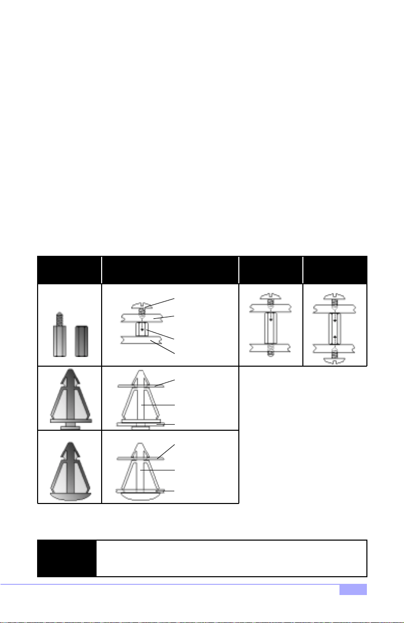
Other examples of how to install your motherboard using other hardware (that may or may not have been
included with your chassis) are shown below.
One solution for installing motherboardType of hardware Another solution Another solution
screw
motherboard
base
stud
chassis wall
The diagrams above are only representative of a few solu tions for installing a
NOTE:
motherboard into the chassis. The installation procedure fo r installing your motherboard may differ.
Thunder i860 S2603
motherboard
base
standoff
chassis wall
motherboard
base
standoff
chassis wall
Figure 2.0
17
Page 18
2.8 Installing Memory
Please keep in mind that although some memory modules may appear to be high-quality, they may contain inferior or substandard parts. The type of memory you choose to install should be checked against
the memory compatibility list, which is available from Tyan’s website at http://www.tyan.com
Memory Installation Procedure
Step
Step
Step
Line up your module so that the pins fit in to the slot. There is only one way your memory
1
module can fit properly. Make sure that the short row of pins is line d up with the short gap in
the RDRAM socket. See Figure 2.1 (on p.17) for graphic det ai ls on how the memor y sh ou ld
be installed.
Insert the memo ry module by pushin g it into t he socket w ith even force. Do not insert one
2
end and then the other: inst all the wh ole modul e at once or you m ight damag e the mem ory
module and/or the socket.
Lock the memory into place by pus hing the clips back on either en d of the socket onto the
3
notches in the ends of the memory module, as shown below.
1 2
Memory Uninstallation Procedure
Removing the RIMM is just the reverse: simply pull back the clips from the memory module (as shown
below), and carefully pull the module straight out. Place the memory modules in an anti-static bag as
soon as you remove them to avoid static damage.
18
NOTE:
21
Also take care that you do not cause yourself injury if you are removing the
memory modules after using the motherboard, since the module(s) may be hot.
http://www.tyan.com
Page 19
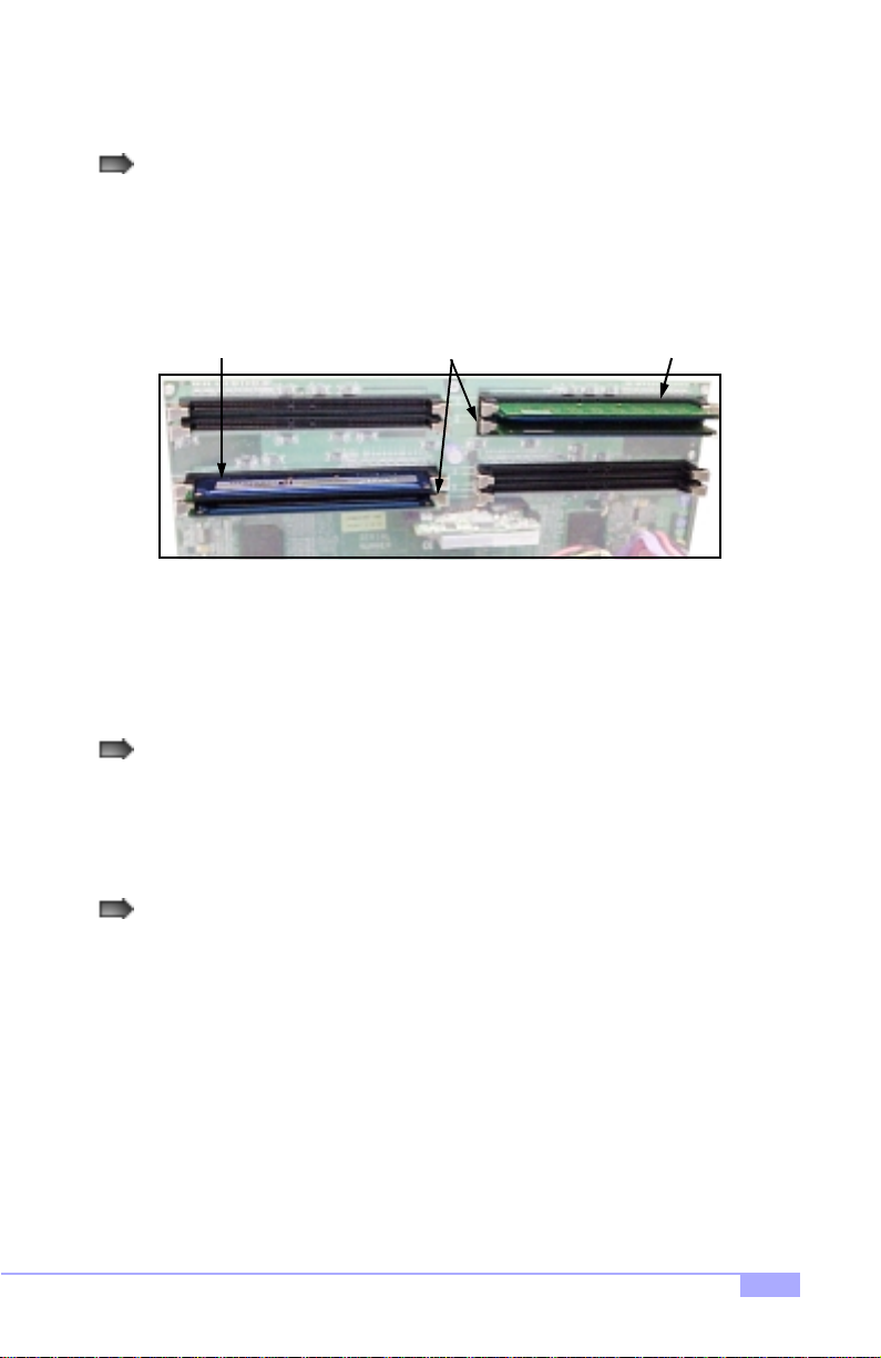
Here are some details of memory installation for this board:
Inner and outer RIMM sockets must be matching (e.g. if you have one RIMM module in the inner
socket, another RIMM module must be installed in the other inner socket, and so on).
See p. 20 and Figure 2.1 (below) for an example.
Inner Modules
Outer Module Outer Module
are matching
Figure 2.1
Any empty slots must be filled with C-RIMM Continuity modules. Tyan has included (2) C-RIMM
modules for your convenience (examples** are shown above in Figure 2.1).
This motherboard supports up to 2GB* PC800 ECC Registered RDRAM. Check the Tyan memory compatibility section of the website for more details: http://www.tyan.com
* not verified at time of print, check the Tyan website for updates: http://www.tyan.com
** note: the examples may not necessarily represent the actual C-RIMMs included with the board.
Thunder i860 S2603
19
Page 20
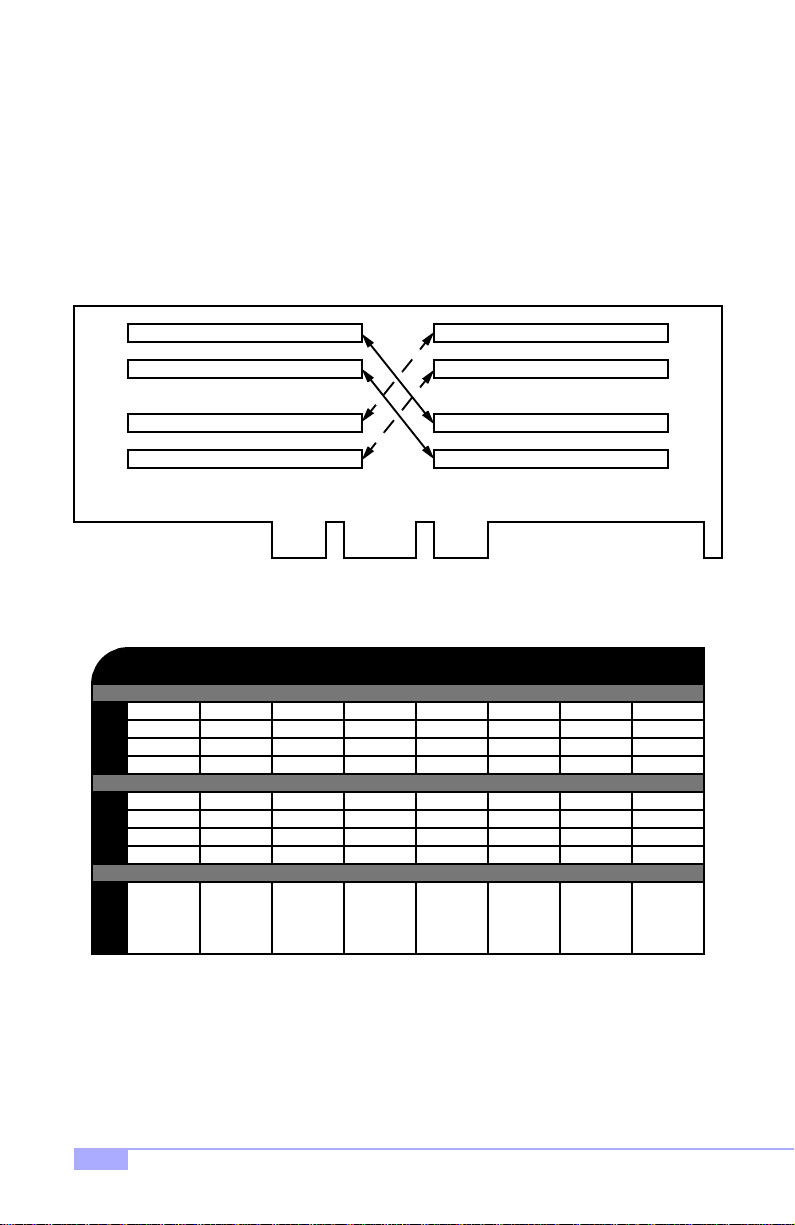
Memory Configuration Examples
Figure 2.2 and the table below should be used in conjunction to determine possible memory configura-
tions. Not all possible configurations are listed. (NOTE: C-RIMM means Continuity RIMM)
NOTE: The Rambus memory modules must be installed in a top-to-bottom fashion (e.g. fill in socket 1,
then socket 2, and match the memory quantity in socket 3 with socket 1’s memory quantity, and then
match the memory quantity in socket 4 with socket 2’s memory quantity, and so on).
A1
A2
D1
D2
C1
C2
B1
B2
64MBx1
C-RIMM
64MBx1
C-RIMM
0
0
0
0
A1
A2
B1
B2
C1
C2
D1
D2
Figure 2.2 - Overhead view of memory banks*
Total of 4GB** PC800 Registered RDRAM possible
64MBx1
C-RIMM
64MBx1
C-RIMM
64MBx1
C-RIMM
64MBx1
C-RIMM
64MBx1
64MBx1
64MBx1
64MBx1
64MBx1
64MBx1
64MBx1
64MBx1
128MBx1
C-RIMM
128MBx1
C-RIMM
128MBx1
C-RIMM
128MBx1
C-RIMM
128MBx1
128MBx1
128MBx1
128MBx1
128MBx1
128MBx1
128MBx1
128MBx1
256MBx1
C-RIMM
256MBx1
C-RIMM
256MBx1
C-RIMM
256MBx1
C-RIMM
512MBx1
C-RIMM
512MBx1
C-RIMM
512MBx1
C-RIMM
512MBx1
C-RIMM
512MBx1
512MBx1
512MBx1
512MBx1
512MBx1
512MBx1
512MBx1
512MBx1
128MB
TOTAL
* RIMM sockets are numbered in the diagram only, as an aid to proper memory installation
** not verified at time of print, check the Tyan website for updates: http://www.tyan.com
256MB
20
512MB 512MB 1024MB 1024MB 4096MB**2048MB**
http://www.tyan.com
Page 21

Due to the memory features of the Thunder i860, the board requires
the use of a Memory Expansio n Card (MEC), shown below.
Configuration of the memory may require Continuity RIMMs (CRIMMs). If C-RIMMs are required, it will be shown in the example.
Please take care to note the shadings in the RIMM sockets, and the
corresponding value in the Installa tio n Le ge nd .
A1
A2
B1
B2
Installation Le gend
= Continuity RIMM = RIMM module = Empty
EXAMPLE 1: 1 pair of RIMMs
A1
A2
B1
B2
C1
C2
D1
D2
EXAMPLE 2: 1 pair of RIMMs
A1
A2
B1
B2
C1
C2
D1
D2
C1
C2
D1
D2
Thunder i860 S2603
EXAMPLE 3: 1 pair of RIMMs
A1
A2
B1
B2
C1
C2
D1
D2
21
Page 22

EXAMPLE 4: 1 pair of RIMMs
A1
A2
B1
B2
EXAMPLE 5: 2 pairs of RIMMs
A1
A2
B1
B2
EXAMPLE 6: 2 pairs of RIMMs
A1
A2
C1
C2
D1
D2
C1
C2
D1
D2
C1
C2
22
B1
B2
EXAMPLE 7: 4 pairs of RIMMs
A1
A2
B1
B2
D1
D2
C1
C2
D1
D2
http://www.tyan.com
Page 23

2.9 Installing the CPU and Cooling Fan
Intel Xeon processors ONLY (1.7* GHz and above*) can be used on the Thunder i860. For more information on CPU compatibility, check Tyan’ s website: http://www.tyan.com.
Remember the following: The CPU is a sensitive electronic component and it can easily be damaged by
static electricity. Do not touch the CPU pins with your fingers. You should be able to insert the CPU into
the socket with virtually no force. Do not press down hard on the CPU as you might bend or break the
pins.
beveled corner
beveled corner
PGA603 CPU socket
Installing the Intel Xeon CPU
Before installing the CPU, check it for damaged. Make sure that none of the pins are bent. There is only
one way to install the CPU. There are two beveled corners in the socket face (shown in the image above)
that match two beveled corners in the CPU pin set. Be very sure that the pins on the CPU match the
socket face pins.
Step
Step
Carefully lift the arm of the ZIF socket until it is at a 90-degree angle
1
pointing away from the motherboard. be very careful not to damage
any components that might be next to the CPU socket. Please note
that each picture for this section (see right) corresponds to the
step.
There are two beveled corners on the CPU pin group, which will
2
match the two an gled corners on the socket face. Carefully install
the CPU by lining both Pin 1 on the CPU and Pin 1 o n the socket
(see right), making sure the pins actually fit into the socket face. Do
not force the CPU into the socke t if it does not fit: check the pin
alignment of CPU pins to socket holes.
1
2
3
Step
* not verified at time of print, check the Tyan website for updates: http://www.tyan.com
Push down lightly on the CPU w hile lo wering the arm of the sock et
3
to secure the CPU (s ee right). A squeaking noise may be hard
while lowering the arm, or the socket may make a ‘click’ noise when
the arm is locked into position: these noises are normal.
Thunder i860 S2603
Arm moves down
to lock CPU
23
Page 24

Installing the Cooling Fan(s)
After a CPU has been installed, you will need to install the prop er cooling d evice for the CPU. This
device, a heatsink/fan com bination , can be purc hased at ma ny compute r retail store s. Installat ion of the
cooling device may vary depe nding on the fan manufacturer ’s design. You should also take space into
consideration when in stall a c ooli n g d evice : m ake su re th e cooling device is not too big, or el se y ou ma y
end up damaging components around the CPU socket.
Tyan highly recommends t hat you use some type of
thermal compound (avai lable from many co mput er ret ail
stores), between the CP U and heat sink, to maximize
distribution of heat away from the CPU. Please use extra
caution when installing any type of clamp-style fan, or
else damage may occur to the CPU socket, and/or the
CPU itself. See the picture to the right for an exa mple
of how to connect the cooling fan’s power supply.
Another diagram has also been provided below, to aid in
CPU fan installation onto the socket. Check with your
cooling device vendor for more details about installation.
Please note that Xeon CPUs require a different cooling device than
that of other socketed CPUs. Check with your vendor for details on
cooling options.
Close-up of fan connector
12
ground
NOTE:
Installing Chassis Fans
Alternatively, if you wish to also install chassis fans for increased cooling, headers are provided to power
those fans as wel l (see p. 15 , section 2.6-H). Chassis fan installation will vary depending on your chassis
manufacturer’s design. Please check with your chassis manufacturer for details on proper chassis fan
installation.
The FAN connector has a 12V, 1.2A limit ation. Tyan takes no responsibility
and will not be held liable for damage related to the misuse of any FAN jumper.
FAN
3
+12V speed
Amperage 1.2A
24
12VVoltage
http://www.tyan.com
Page 25

2.10 Connecting IDE and Floppy Drives
A variety of IDE a nd ATAPI-compliant devices can be i nstalled on this m otherboard, su ch as hard disk
drives (HDDs) and CD-ROMs.
Please keep in mind that on this mothe rboard, the primary IDE connec tor is BLACK, and the secondary IDE
connector is WHITE. See the picture to the rightfor an
example of the IDE cable properly connected to the
motherboard, with the BLUE end of the IDE cable
installed on the motherboard .
Pin 1 on the IDE cable is usually denoted by a red or colored stripe down o ne side of the cable. That side o f the
cable must match Pin 1 on the motherboard’s IDE connector. There will also be a key pin on the cable that
matches with a notch in the ID E connector, to ensure
proper installation. Consult the documentation that came
with your IDE/ATAPI device, or contact the device’s
manufacturer for more details on installation.
Please note that UltraDMA-100/66 IDE HDDs require a
special 80-wire cable which has additional grounding
wires. This cable has been incl uded with this motherboard for your convenience. The UltraDMA-100/66
cable is backwards compatible with UltraDMA-33 and
legacy IDE HDDs.
BLUE end goes to IDE connector
Pin 1
Only Tyan-approved cables are recommended for this mo the rbo ard . If you a re using
NOTE:
Hard Disk Drive Fail message at bootup
No video or beeps during bootup
an existing configuration with older cables, your system might not function pro perly.
Use only Tyan-approved cables (i.e. the ones included with your mothe rbo ar d).
Some symptoms of incorrectly installed HDDs are...
HDDs are not auto-detected
HDD lights are constantly on
HDD does not power on
Thunder i860 S2603
May be a Master/Slave configuration problem, bad
IDE cable, or BIOS mis-configuration. Consult the
HDD documentation or contact your HDD vendor.
May be a bad cable or lack of power going to the
drive. Check the cables for damage and bad connections.
Usually means the cable was installed backwards.
Bad IDE cable or defective drives/motherboard. Try
another HDD, or contact your HDD vendor.
Check power cables and cabling. May be a bad
power supply or IDE drive problem.
25
Page 26

Connecting Floppy Drives
See the pictu re be low for an example of a fl oppy cab le. Most of the current floppy drives on the ma rket
require that the cable be instal led with th e colored str ipe positi oned ne xt to the power connector. In most
cases, there will be a key pin on the cable which will force a proper connection of the cable.
The first floppy drive (someti mes denot ed as A:) is usually attached to the end of the cable with the twist in it.
Drive B: is usually conn ected to the second or th ird connector in the cable (the se cond or third connector a fter
you install Drive A:). Refer to your floppy drive’s installation instructions (if available), or contact your dealer if
you are unsure about how to attach the floppy drive(s).
Remember, you can only have 2 floppy drives connected at any given time.
Pin 1
3.5” connector
This connec tor goes
to motherboard
Drive B:Drive A:
5.25” connector Colored stripe
Figure 2.4*
Some symptoms of incorrectly installed FDDs are...
FDDs are not auto-detected
Floppy Drive Fail mes sag e at bo otup
FDD does not pow er on
FDD light is constantly on
Colored stripe
indicates Pin 1
indicates Pin 1
Usually caused by faulty cables, cabl es put in backwards, or a bad floppy or motherboard. Try another
floppy drive to verify the problem or try another
cable. Also check to see if the onboard floppy is
enabled in the BIOS.
The cable, floppy, or motherboard may be faulty. Try
another cable or floppy drive to verify.
Check power cables and cabling. May be a bad
power supply or IDE drive problem.
Usually signifies that the cable is on backwards.
Reverse the cable at the floppy drive end and try
again.
Match striped side with Pin 1
* Cable may vary. D iagram provided for reference only.
26
http://www.tyan.com
Page 27

2.11 Installing Add-on Cards
There are a few rules you need to follow when installing add-on cards. In order to assure proper operation
and a quick installation, adhere to the following guidelines:
If you are going to install a PCI-bus interface card on your system, be aware that any one of the
five PCI slots can support a Master or Slave device.
NEVER force a card into a slot. If it doesn’t fit, look at the socket on the motherboard to make
sure there are no wires or other obstructions to the slot.
NEVER plug an ISA card into a PCI slot. You will void your warranty and damage your system
board if you do this.
When plugging the card in, especially when installing long cards, try to push the entire card in at
one time. Don’t force one end of the card into the socket first and then the other, or a rocking
motion between the card and the slot might occur, and could damage the pins within the socket.
Make sure the cards are seated securely into their slots.
Before turning on the system, make sure no cards are touching.
Check the PCI device specifications with the PCI slot specifications (p.5) BEFORE installing!
When installing the add-on cards, make sure the cards are installed with even force; do not insert one
end and then the other. See the before (Figure 2.1a) and after (Figure 2.1b) example in sta l la t ion i ma g es
below for details.
1
Check orientation of card when installing
Figure 2.1a*
2
Push card down with even force
Figure 2.1b*
* diagrams are provided as an example for installation, and may not represent an actual slot
Thunder i860 S2603
27
Page 28

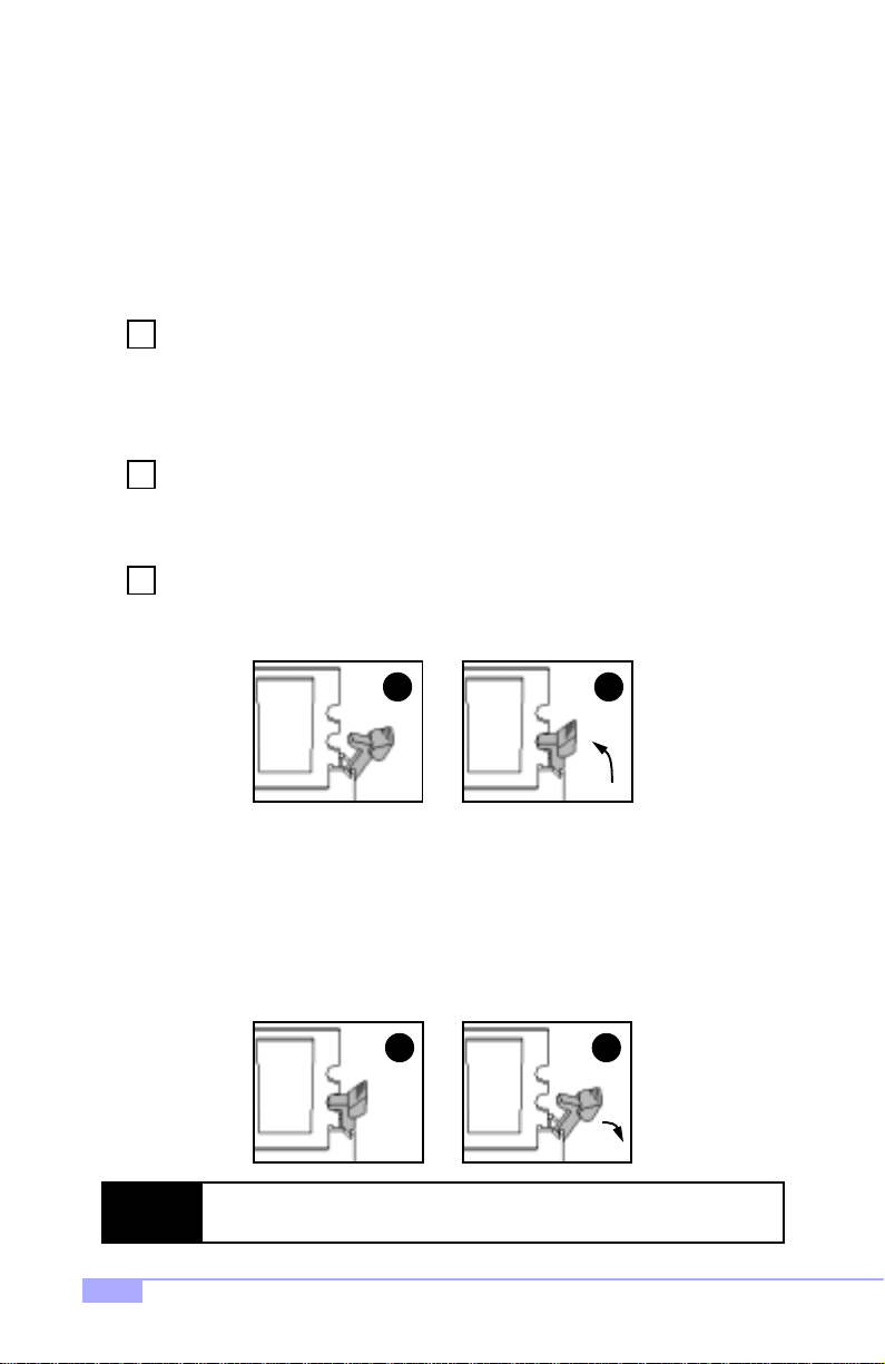
About the AGP Pro slot
If you are planning to install an AGP Pro, Pro 50, or 4X AGP Pro 50-compliant card, a small plastic retention piece must be removed from the AGP Pro slot before the card can be installed.
1 2
Figure 2.2a Figure 2.2b
First, make sure the card you’re installing is an AGP Pro-compliant card. Next, locate the small plastic
retention piece in the AGP Pro slot (Figure 2.2a, above), and use a tool with a small hard tip (such as a
pen) to remove the retention piece (Figure 2.2b, above). Tyan recommends you save this piece for
future use (e.g. in case a regular AGP card is installed later on).
T o further ensure that the AGP card will not rock back and forth, make sure that the metal endpiece of the
AGP card is flush with the motherboard edge.
Only remove the small plastic retention piece if you are going to install an AGP
Pro-compliant card. Installing a regular AGP card without the retention piece can
cause the card to rock back and forth, possibly dam ag ing the card and /or moth er-
NOTE:
board.
Tyan takes no reponsibility for and will not be held liable for damage related to use
of regular AGP cards without the retention piece installed.
28
http://www.tyan.com
Page 29

2.12 Connecting PS/2, USB, and Serial Devices
This motherboard includes ports for PS/2 mouse and keyboard, Universal Serial Bus (USB) devices, and
serial and parallel devices. Please not e that the upper PS/2 port is the mouse port, and the lower PS/2
port is for the keyboard (see Figure 2.3 below).
Installation of peripheral/external devices may vary. For details on installation of devices into the various
ports shown below, please consult your device’s documentation, device manufacturer, or your dealer for
details.
Connecting Serial and Parallel Ports
The serial and parallel ports can be used to connect various devices such as a mouse or printer. The connectors can only be connected one way: be sure and check the orientation of the connector before installing it into the port.
PS/2 Mouse Port
PS/2 Keyboard Port
USB Ports Parallel Port
Serial Port 1 LAN portSerial Port 2 Line-out*
Line-in* Mic-in*
Figure 2.3
* indicates an optional feature available on some Thunder i860 models
Thunder i860 S2603
29
Page 30

2.13 Connecting the power supply
This motherboard requires a dual Xeon-compatible power supply, such as the NMB
IT002A430WSW.
Step
The power supply for the Thunder
1
i860 has two power plugs, with
clips.
Both plugs must be installed in order
to properly run the Thunder i860 !
Failure to install both plugs may
result in damage to the bo ar d!
Note the clip
Figure 2.4a
Step
Step
Step
Shown on the right are two images of
2
the 8-pin power plug.
This plug should be installed first to
ensure that the board will operate
properly.
When you install the plugs, make sure
the clips are install ed ov er the power
socket tabs.
The other power plug has 24-pins.
3
This plug also needs to be installed.
The 24-pin power plug is shown on
the right.
Take extra care that the clip matches
4
the power socket tab on the 24-pin
power connector as well.
Make sure all pins have been connected, or damage may occur to the
board.
Tyan takes no reponsibility and will
not be held liable for da ma ge due
to incorrect power supply installation.
Figure 2.4c
Note the clip
Figure 2.4b
Figure 2.4d
30
http://www.tyan.com
Page 31

You are done!
Other than checking the jumper settings and cable connections, and putting the case back together, you
are done.
Installing a new motherboard may seem difficult, but by following these directions, you should have a
fairly uneventful time installing our products. If you do encounter problems, your dealer will be able to help
you, or you can consult one of our many technical support resources (see p. 7).
Thunder i860 S2603
31
Page 32

2.14 Frequently Asked Questions (FAQ)
Q: My system sometimes becomes unstable. How should I check the system?
A: The first thing to do is to check and see if you have any device conflicts related to the IRQ, or DMA. If
you are using Microsoft Windows, the Control Panel is a good place to start investigating the conflict.
Please consult your operating system documentation for details. Secondly, slowing down the memory timing in the BIOS’ chipset setup section might help the situation as well. Many memory modules are not
suitable for high performance systems and might be the main source of your problem. Also check to make
sure you are using a dualXeon-capable, APPROVED* or better power supply. Lastly, make sure the
motherboard is receiving adequete cooling.
Q: I have a question about memory compatibility; what memory will work on my motherboard?
A: Memory compatibility information can be found on Tyan’s website at: http://www.tyan.com
Q: Where can I get additional accessories for my Tyan motherboard?**
A: You can purchase additional Tyan-approved accessories** at the Tyan Computer Online Store:
http://www.etyan.com
Q: Where do I get pinout information for my motherboard?
A: Pinouts of certain headers are available on the Tyan website: http://www.tyan.com
Q: My motherboard is dead, how do I return it?
A: Contact the place of purchase or your distributor f or assistance to return the mot herboard for service.
RMA issues will not be handled via e-mail by Tyan Tech Support. Please refer to the URL link here for
more details: http://www.tyan.com/support/html/rma_faq.html
Q: How do I upgrade my BIOS?
A: Check the section about the Flash Utility (see p. 47) for information on upgrading your BIOS. BIOS
update files, flash utilities, and instructions on how to install them are also available from the Tyan website
at: http://www.tyan.com
Q: Why do I get a “CMOS checksum invalid” error message during POST?
A: If you get the above error message or “Invalid configuration, run Setup” message, it is an indication that
the CMOS battery needs to be changed. Contact your dealer for assistance. Once you’ve replaced your
battery or flashed your BIOS, don’t forget to check the CMOS Reset section (see p.12) so that you can
reset your CMOS.
* Check the Tyan website for updates: http://www.tyan.com
** Please check that your chassis is frontside USB capable if that is a feature you are planning to
implement . Please check with your chassis vendor for details.
32
http://www.tyan.com
Page 33

Chapter 3: BIOS Setup
Introduction to the BIOS setup
The BIOS is the basic inpu t/output syst em, requ ired by the computer to perform functions suc h as CPU
and hard drive supp ort . T his ch apt er des cri be s differe nt settings for the BIOS t hat can be use d to co nfigure your system.
The BIOS section of the manual is subject to change without notice and is provided here for reference purposes o nly. The settings an d conf iguration s of the BIOS are current at the t ime of pr int,
and therefore they may not be exactly the same as that displayed on your screen.
This manual describes the BIOS setup prog ram. The setup pro gram lets y ou modify b asic conf iguration
settings. The settings are the n sto red in a de dicated battery-backed memo ry, called NVRAM, that re tai n s
the information when the power is turned off.
The BIOS in your motherboard is a customized version of an industry-standard BIOS for IBM PC AT-compatible personal comput ers. It supports Intel x86 and compatible processo rs. The BIOS provides cri tical
low-level support for the system central processing, memory, and I/O subsystems.
The BIOS has been customized by add ing i m por tan t, but non- stan da rd, featu re s such as vir us and password protection, power management, a nd detailed fine- tuning of the ch ipset controlling the s ystem. The
rest of this manual is intende d to guide you through the process of configuring y our system using this
BIOS setup program.
Starting Setup
The BIOS is immediately a cti vat ed wh en yo u fi rs t tur n on the co mp ute r. The BIOS reads s ystem con figuration information in CM OS RAM and be gins the pro cess of checking out the system and configur ing it
through the Power-On Self Test (POST).
When these preliminaries are finishe d, the B IOS seeks a n operat ing system on one of t he data storage
devices (HDD, floppy drive, etc.) If one is found, the BIOS will launch that operatin g system and hand
control of system operations to it. You can start the setup program by pressing the [F2] key while the system is booting up.
Thunder i860 S2603
33
Page 34

Setup Keys
The table below shows how to navigate in the setup program using the keyboard.
Key Function
Tab
Left/Right Arrow Keys
Up/Down Arrow Keys Move between selections
Enter
PgUp/PgDn Keys
Getting Help
Press [F1] to display a small help win dow that describ es the appropr iate keys to use and the possib le
selections for the highlighted item. To exit the Help Window press [ESC] or the [F1] key agai n.
In Case of Problems
If you discover that you have trouble booting the com puter after making and saving changes with the
BIOS setup program, you can restart the computer by either:
Holding the power button down until the computer shuts off
The best advice is to alte r only sett ings th at you th oroughl y under stand. I n particu lar, do not change settings in the Chipset scr een un less you ab solutely sure that you ne ed to. Th e Chi pse t d efa ults were ca refully chosen by Tyan or your system manufacturer for the best performance and reliability. Even a
seemingly small change to the Chipset setup may cause the system to become unstable.
Moves from one selection to the next
Change from one menu to the next
Opens highlighted section
Change setting
Setup V ariations
Not all systems have the same setup program. While th e basic look and functio n of the setup program
remains more or le ss th e sam e f or all sy stem s, t he ap pea ran c e of your Setup screen may differ fr om the
screens shown here. Each sy stem design and chipset combination requ ire custom configurations. In
addition, the fina l appearance of the setup pr ogram depends on your system designer. Your system
designer can decide tha t certain item s should not be available for use r configurati on, and remove t hem
from the BIOS setup program . NOTE: I tems m arked with “ (opti onal)” deno te feat ures that m ay not
exist in your BIOS setup.
34
http://www.tyan.com
Page 35

3.1 Main Setup
In this screen, you can alter general features such as the date and time, as well as access the IDE configuration screens. Note t hat the options listed be low ar e f or options that can dir ectly b e ch an ged withi n the
Main Setup screen.
FORMAT: y/n
Enable ACPI (debug only)
OPTIONS:
NOTES: Deb ug pur po ses only
Yes / No
Operating System
Reset Configuration Data
System Time
System Date
FORMAT:
OPTIONS: Win98
NOTES: Choose ‘Other’ for other OS
FORMAT: [option]
OPTIONS:
NOTES: Select Yes when required to restore the manu-
FORMAT:
OPTIONS: hh = hours
NOTES: System time works on 24-hour format
FORMAT:
OPTIONS: mm = month
[option]
WinME
Win2K
NT4/Linux/Other
Yes Erases all configuration
No Does not erase ESCD.
facturer’s defaults.
hh:mm:ss
mm = minutes
ss = seconds
mm/dd/yyyy
dd = day
yyyy = year
data in a section of memory for ESCD (Extended
System Configuration
Data) which stores the
configuration settings for
non-PnP plug-in devices.
Thunder i860 S2603
35
Page 36

3.2 Advanced Setup
Options such as I/O device interfaces can be altered through the sub scre ens listed in this setup screen.
Processors Discussed below
Chipset Discussed on p. 37
Floppy Disk Drive Discussed on p. 37
IDE Devices Discussed on p. 38
Integrated SCSI Controller Discussed on p. 39
Integrated Network Interface Discussed on p. 39
Integrated I/O Ports Discussed on p. 40
Integrated Audio Discussed on p. 42
AGP Slots (Graphics) Discussed on p. 42
PCI Device, Slot #1 (.. 2, 3) Discussed on p. 43
PCI Device, Slot #4 (64-bit) Discussed on p. 43
PCI Device, Slot #5 (64-bit) Discussed on p. 43
3.2-A. Processors screen (optional)
Options related to the processors can be altered through this screen.
FORMAT:
OPTIONS: 800MHz, 900MHz, 1.00GHz, 1.10GHz,
Processor Speed
NOTES: Selects the speed of your CPU.
[speed]
1.20GHz, 1.30GHz, 1.40GHz, 1.50GHz,
1.60GHz, 1.70GHz, 1.80GHz, 1.90GHz,
2.00GHz, 2.10GHz, 2.20GHz, 2.30GHz
DO NOT USE A HIGHER SETTING THAN
YOUR CPU CAN HANDLE ACCORDING TO
MANUFACTURER’S SPECIFICATIONS.
36
http://www.tyan.com
Page 37

3.2-B. Chipset screen
Options related to the chipset functions can be altered through this screen.
Memory Hole
ECC Config
ECC Error Type
SERR Signal Condition
FORMAT: [option]
OPTIONS:
NOTES: Select Yes when required to restore the manu-
FORMAT: [option]
OPTIONS:
NOTES: Select Yes when required to restore the manu-
FORMAT: [option]
OPTIONS:
FORMAT: [option]
OPTIONS:
Extended Specifies if there is a sec-
No No memory hole.
facturer’s defaults.
Disabled No error checking.
ECC (multiple bits) Error checking & status
facturer’s defaults.
None
SMI
SCI
NMI Non-Maskable Interrupt
None
Single bit
Multiple bits
Both ERR signal output for
tion of memory that cannot be addressed by the
ISA bus. If the memory
hole exists, extended
memory will handle it.
report enabled. Data is
corrected.
No error type specified
Structure of Management
Information
System Control Interrupt
ERR signals not output
under any condition.
ERR signal output for a
single bit
ERR signal output for
multiple bits
both instances.
3.2-C. Floppy Disk Drive scree n
Options related to the Floppy Drive interface can be altered through this screen.
FORMAT:
OPTIONS: 360KB, 5 1/4”
Floppy Disk Drive A:
NOTES: This option is provided for your floppy device
[size in MB] [media dimensions]
1.2MB, 5 1/4”
720KB, 3 1/2”
1.44/1.2 5MB, 3 1/2”
2.88MB, 3 1/2”
Not Installed
Disabled
needs. It is also linked to the Boot Sequence
in the Boot Menu.
Thunder i860 S2603
37
Page 38

3.2-D. IDE Devices screen
Options related to the PCI slots can be altered through this screen.
Primary Master/Slave Discussed below
Secondary Master/Slave Discussed below
Type
Multi-Sector Transfers
FORMAT:
OPTIONS:
NOTES: All options are dependent on the drive.
FORMAT: [option]
OPTIONS:
NOTES: All options are dependent on the drive.
[option]
None
1 to 39
User The user must define the
Auto Auto-detect the drive
IDE Removeable Removeable read-and-
CD-ROM Readable CD-ROM drive.
AT API Removeable Removeable ATAPI media
Disabled DIsables the feature.
Standard Standard is 1 sector per
2 sectors
4 sectors
8 sectors
16 sectors
Auto-typing is not able to
supply the drive type, or
the user ha s selected
None to disable any
drives that might be
installed.
Pre-configured drive
parameters. This option is
dependent on your drive.
different parameters of
the drive.
parameters.
write media (e.g. Zip
drive).
(e.g. USB Zip drive).
block.
Number of sectors trans-
ferred per block.
LBA Mode Control
32-bit I/O
(continued on next page)
38
FORMAT:
OPTIONS:
NOTES:
FORMAT:
OPTIONS:
NOTES:
[option]
Disabled / Enabled Enabling LBA causes logi-
All options are dependent on the drive.
[option]
Disabled / Enabled Enables 32-bit communi-
All options are dependent on the drive.
cal block addressing to be
used in place of Cylinders, Heads, and Sectors.
cation between CPU and
IDE card. Requires PCI or
local bus.
http://www.tyan.com
Page 39

(continued from previous page)
Transfer Mode
UltraDMA Mode
Large Disk Access Mode
Integrated IDE Controller
FORMAT:
OPTIONS:
NOTES: The Setup menu only lists those options sup-
FORMAT:
OPTIONS:
NOTES:
FORMAT:
OPTIONS:
NOTES: A large disk is one that has more than 1024
FORMAT:
OPTIONS:
[option]
Standard
Fast PIO 1
Fast PIO 2
Fast PIO 3
Fast PIO 4
FPIO 3 / DMA 1
FPIO 4 / DMA 2
ported by the drive and platform.
[option]
Disabled
Mode 0
Mode 1
Mode 2
Mode 3
Mode 4
Mode 5
The Setup menu only lists those options supported by the drive and platform.
[option]
Other Select Other if you have another
operating system such as UNIX.
cylinders, more than 16 heads, or more than
63 tracks per sector.
[option]
Both Channels
Disabled
Primary
Secondary
Selects the method for
transferring data between
the HDD and system
memory.
Selects UltraDMA mode
for the installed device.
Selects the IDE channels
to be used.
Thunder i860 S2603
39
Page 40

3.2-E. Integrated SCSI screen
Options related to the integrated SCSI controller can be altered through this screen.
Integrated SCSI
FORMAT: [option]
OPTIONS:
NOTES: Enables or disables the integrated SCSI
Enabled / Disabled
FORMAT: [option]
Option ROM Scan
Enable Master
Latency Timer
3.2-F. Integrated Network screen
Options related to the integrated LAN controller can be altered through this screen.
Integrated Network
Option ROM Scan
Enable Master
OPTIONS:
NOTES: Enables or disables the SCSI option ROM (if
FORMAT: [option]
OPTIONS:
NOTES: Enables or disables bus mastering on the
FORMAT:
OPTIONS: Default, 0020h, 0040h, 0060h, 0080h, 00A0h,
NOTES: Sets the bus master clock rate. A device that
FORMAT: [option]
OPTIONS:
NOTES: Enables or disables the integrated LAN
FORMAT: [option]
OPTIONS:
NOTES: Enables or disables the LAN option ROM (if
FORMAT: [option]
OPTIONS:
NOTES: Enables or disables bus mastering on the LAN
Enabled / Disabled
present)
Enabled / Disabled
SCSI controller
[address]
00B0h, 00C0h, 00E0h
has high priority and high throughput may benefit from a greater value.
Enabled / Disabled
Enabled / Disabled
present)
Enabled / Disabled
controller
40
Latency Timer
FORMAT:
OPTIONS: Default, 0020h, 0040h, 0060h, 0080h, 00A0h,
NOTES: Sets the bus master clock rate. A device that
[address]
00B0h, 00C0h, 00E0h
has high priority and high throughput may benefit from a greater value.
http://www.tyan.com
Page 41

3.2-G. Integrated I/O Ports screen
Options related to the integrated I/O interface ports can be altered through this screen.
FORMAT: [option]
OPTIONS:
Serial Port A (.. B)
Disabled ‘Disabled’ turns off the
Enabled ‘Enabled’ requires you to
Auto ‘Auto’ makes the BIOS
port.
enter the base I/O
address and the INT number on the next line.
configure the port during
POST.
Base I/O
Interrupt
Parallel Port
Mode
FORMAT: [option]
OPTIONS:
NOTES: Recommended combinations include ‘3F8,
FORMAT: [option]
OPTIONS:
NOTES: Recommended combinations include ‘3F8,
FORMAT: [option]
OPTIONS:
FORMAT: [option]
OPTIONS:
3F8, 2F8
3E8, 2E8
IRQ4’ and ‘2F8, IRQ3’.
IRQ4
IRQ3
IRQ4’ and ‘2F8, IRQ3’.
Disabled ‘Disabled’ turns off the
Enabled ‘Enabled’ requires you to
Auto ‘Auto’ makes the BIOS
Output only Standard one-way proto-
Bi-directional Two-way protocol for par-
EPP Enhanced Parallel Port
ECP Enhanced Capability Port
These options are dependent on the IRQ, and vice
versa.
These IRQs are paired
with the Base I/O option.
port.
enter the base I/O
address and the INT number.
configure the port during
POST.
col for parallel devices.
allel devices.
interface may provide
higher bandwidth, if an
EPP device is used.
interface may provide
higher bandwidth, if an
ECP device is used.
(continued on next page)
Thunder i860 S2603
41
Page 42

(continued from previous page)
FORMAT: [option]
Base I/O
Interrupt
3.2-H. Integrated Audio screen (optional)
Options related to the integrated audio can be altered through this screen.
Integrated Audio
Enable Master
Latency Timer
OPTIONS:
FORMAT: [option]
OPTIONS:
FORMAT: [option]
OPTIONS:
NOTES: Enables or disables the integrated audio
FORMAT: [option]
OPTIONS:
NOTES: Enables or disables bus mastering for the
FORMAT:
OPTIONS: Default, 0020h, 0040h, 0060h, 0080h, 00A0h,
NOTES: Sets the bus master clock rate. A device that
378
278
3BC
IRQ5
IRQ7
Enabled / Disabled
Enabled / Disabled
audio controller
[address]
00B0h, 00C0h, 00E0h
has high priority and high throughput may benefit from a greater value.
These options appear
when the parallel port is
set to ‘Enabled’.
These options appear
when the parallel port is
set to ‘Enabled’.
3.2-I. AGP Slot (Graphics) screen
Options related to the AGP slot can be altered through this screen.
FORMAT: [option]
Enable Master
Latency Timer
Graphics Aperture
OPTIONS:
NOTES: Enables or disables bus mastering for the AGP
FORMAT:
OPTIONS: Default, 0020h, 0040h, 0060h, 0080h, 00A0h,
NOTES: Sets the bus master clock rate. A device that
FORMAT: [option]
OPTIONS:
Enabled / Disabled
video controller
[address]
00B0h, 00C0h, 00E0h
has high priority and high throughput may benefit from a greater value.
4MB
8MB
16MB
32MB
64MB
128MB
256MB
42
Sets the size of the memory area reserved for storage of graphics data
structures used by the
AGP.
http://www.tyan.com
Page 43

3.2-J PCI Device, Slot #1 (.. 2, 3, 4, 5) screen
Options related to the PCI slots can be altered through the se screens (each PCI slot allotted a single
setup screen).
FORMAT: [option]
OPTIONS:
PCI Device, Slot 1 (..2, 3, 4, 5)
3.3 Security Setup
Options such as password protection can be altered through this setup screen.
FORMAT: [press the [ENTER] key]
OPTIONS:
Set Administ ra tor Password
FORMAT: [press the [ENTER] key]
OPTIONS:
Set User Password
Option ROM Scan Enables or disables
(Enable or Disable)
Enable Master Enables selected device
(Enable or Disable)
Latency Timer Sets the bus master clock
(0020h, 0040h,
0060h, 0080h,
00C0h, Default)
[Enter] Enter up to 16 alphanu-
[Enter] Enter up to 16 alphanu-
device expansion ROM.
as a PCI bus master. Not
every device can function
as a master. Check your
device documentation.
rate. A device that has
high priority and high
throughput may benefit
from a greater value.
meric characters. You will
be asked to confirm the
password. In related systems, features will be
accessible only by users
who use the supervisor
password.
meric characters. You will
be asked to confirm the
password. This feature
will not be enabled if there
is no administrator password set.
Power-on Password
(continued on next page)
Thunder i860 S2603
FORMAT: [press the [ENTER] key]
OPTIONS:
[Enter] Enter up to 16 alphanu-
meric characters. You will
be asked to confirm the
password. This feature
will not be enabled if there
is no administrator password set.
43
Page 44

(continued from previous page)
FORMAT: [option]
Start from floppy
Start from CD-ROM
Start from HDD
Hardware Protection Discussed below
Write on floppy disks
Locked Setup Configuration
Hard Disk Root Sector
OPTIONS:
FORMAT: [option]
OPTIONS:
FORMAT: [option]
OPTIONS:
FORMAT: [option]
OPTIONS:
FORMAT: [option]
OPTIONS:
FORMAT: [option]
OPTIONS:
Disabled
Enabled
Disabled
Enabled
Disabled
Enabled
Locked
Unlocked
Yes
No
Locked
Unlocked
Enabling this feature
allows booting from the
floppy device.
Enabling this feature
allows booting from the
CD-ROM device.
Enabling this feature
allows booting from the
HDD device.
Selecting ‘Locked’ will
prevent write access to
the floppy device.
Selecting ‘Yes’ will prevent access to the BIOS
setup.
Selecting ‘Locked’ will
prevent access to the
HDD root sector.
44
http://www.tyan.com
Page 45

3.4 Power Setup
Options related to the onboard power functions can be altered through this setup screen.
Remote Power-on
FORMAT: [option]
OPTIONS:
Disabled
Enabled
If enabled, the system can
be powered on from a
remote location.
FORMAT: [option]
OPTIONS:
After Power Failure
3.5 Boot Setup
Options related to the boot functions can be alter ed throu gh this setup screen .
FORMAT: [option]
Quickboot Mode
Disp Option ROM Messages
Preferred Video
Summary Screen
OPTIONS:
FORMAT: [option]
OPTIONS:
FORMAT: [option]
OPTIONS:
FORMAT: [option]
OPTIONS:
Stay off System stays off after
Power on System will automatically
Last state System will automatically
Disabled
Enabled
Disabled
Enabled
PCI
AGP
Disabled
Enabled
power is lost.
power on when a power
input signal is detected by
the BIOS.
power on and retain the
last state it was in, once a
power input signal is
detected by the BIOS.
If enabled, boot time will
decrease but some tests
will not be run in POST.
If enabled, messages
from each option ROM
will be shown.
Selects preferred video
bus to initialize at bootup
time.
If enabled, the boot summary screen will show
during bootup.
Boot Device Priority Discussed below
FORMAT: [option]
OPTIONS:
(menu dependent on devices
detected
Thunder i860 S2603
(dependent on
devices detected)
Each item detected as a
removeable device, will
be listed in this section.
As the user presses the
‘+’ key, the item will move
up in priority. The item at
the top will take first priority, the second item takes
next highest priority, and
so on.
45
Page 46

3.6 Exit Setup
This screen shows options for exiting the BIOS setup.
FORMAT: [option]
Exit Saving Changes
OPTIONS:
Yes
No
Saves changes to CMOS
and exits BIOS setup.
Exit Discarding Changes
FORMAT: [option]
OPTIONS:
Yes
No
Discard any changes and
then exit BIOS setup.
46
http://www.tyan.com
Page 47

Chapter 4: System Resources
Note: If you experience problems with setting up your system, always check the following things in the
following order:
MEMORY, VIDEO, CPU
By checking these items, you will most likely find out what the problem might have been when setting up
your system. For more information on troubleshooting, check the Tyan website at http://www.tyan.com
4.1 Beep Codes
Fatal errors, which halt the boot process, are communicated through a series or audible beeps. For example, if the Phoenix BIOS POST can initialize the video but an error occurs, an error message will be displayed. If it cannot display video, it will convey a series of beeps.
If you hear one long beep followed by two short beeps, then a video problem has probably occured and
the BIOS is having difficulty initializing the video display. Any other beep sequences that may or may not
occur are probably due to memory problems.
4.2 Flash Utility
Every BIOS file is unique for the motherboard it was designed for. For Flash Utilities, BIOS downloads,
and information on how to properly use the Flash Utility with your motherboard, you must check the Tyan
website: http://www.tyan.com
Please be aware that by flash ing your BIOS, you a gree that in the eve nt of a BIOS
flash failure, you must contact your dealer fo r a replacement BIOS. T here are no
NOTE:
exceptions. Tyan does not have a policy of replacing B IOS chips directly with end
users. In no event will Tyan be held responsible for damage done to the BIOS by the
end user.
Thunder i860 S2603
47
Page 48

Appendix I: SCSI Installation* and LAN Information
Introduction
With the dual channel onboard Ultra160 LVD SCSI option*, you can connect up to 30 SCSI peripherals
such as hard drives, CD-ROMs, and tape drives. Please note that this guide only provides basic instructions on connecting SCSI devices to your motherboard. For more detailed SCSI installation instructions,
refer to your SCSI device documentation or to LSI Logic’s website: http://www.lsilogic.com
Features* of the LSI Symbios SCSI BIOS
Configuration for up to 256 adapters - any 4 can be chosen for INT13
(bootrom) s upport
SPI-3 Parallel Protoc ol Request (PPR)
Basic Domain Validation
Legacy support fo r no n- U ltr a1 60 SC S I devices
The LVD signaling used for Ultra160 devices operates differently than single-ended signaling used on
Ultra, Fast, and Fast Wide SCSI devices. Ultra160 LVD SCSI devices are designed with multi-mode capability so that if a single-ended device is connected to the Ultra160 LVD SCSI bus, the Ultra160 devices
automatically switch to single-ended mode. When an Ultra160 LVD SCSI device operates in single-ended
mode it is subject to the cable distance limitations and signal noise problems of that interface. LSI recommends that single-ended Ultra and earlier devices be kept on a separate channel than the Ultra160 LVD
SCSI devices. This will permit the Ultra160 devices to operate at full speed and cable distances.
Setting up internal SCSI peripherals
Its very important that SCSI peripherals be set up before installing them to the SCSI connector. The setup
for SCSI peripherals usually involves setting SCSI IDs, checking for termination, mounting the peripherals
inside the chassis, and then hooking up power to each peripheral. Since setup can vary from peripheral to
peripheral, always refer to the peripherals documentation for specific instructions. Below are some guidelines for s etting SCSI IDs and termination on your peripherals.
Checking SCSI IDs
Both the motherboard SCSI connectors and each peripheral you connect need to have a unique ID, ranging from 0 t o 15. IDs do not have to be sequential, as long as each connector and each peri pheral has a
different number for each channel. Each SCSI channel on the motherboard is preset to SCSI ID and
should not be changed. If you will be booting from a SCSI HDD, its best to set the disk’s ID at 0 or 1. Most
SCSI HDDs come from the factory preset to ID 0. The IDs for internal peripherals are usually set with
jumpers; external peripherals are usually set with a switch on the back of the peripheral. Check your
peripheral’s documentation for more details.
Terminating SCSI devices
T o ensure reliable communication on the SCSI bus, the peripheral on the end of each cable, or the end of
the cable itself, must have a terminator installed (or enabled). The peripherals between the ends of each
cable must have the terminator removed (or disabled). Check your peripheral’s documentation for more
details.
Connecting SCSI peripherals
A total of 30 SCSI peripherals can be connector to the onboard SCSI connectors (15 devices per channel/
connector). Before connecting peripherals, be sure to also review Setting up internal SCSI peripherals
above.
Connecting internal cables for Ultra160 LVD SCSI devices
When connecting internal Ultra160 LVD peripherals there are special SCSI cables necessary to sustain
the higher speeds of LVD signaling. If your cables are not marked, you can identify most Ultra160 LVD
SCSI cables as having twisted pairs of the flat ribbon cable in between the device connectors. These
cables will usually have a terminator built into the end of the cable.
48
http://www.tyan.com
Page 49

Step
Locate the 68-pin internal Ultra160 LVD SCSI cable (it should look similar to the one
1
shown directly below).
Built-in terminator
Connect to motherboard
Connect to Ultra160 LVD
peripherals
Ultra160 LVD SCSI con-
nector
Step
Step
Plug the long end of th e cabl e (s ) to th e Ul tr a1 60 LVD SCSI co nnec to r (s) on th e mo th er -
2
board (either channel A or channel B). Note that the image(s) below may not be completely representative of your motherboard.
Channel A
Channel B
Plug the remaining connectors to the internal Ultra160 LVD SCSI peripherals.
3
Terminator device
Internal Ultra160 SCSI peripherals come from the factory without termination. Proper
NOTE:
termination is pro vided by the built-in termina tor at the end of the Ult ra160 internal
SCSI cable.
Thunder i860 S2603
49
Page 50

Information on the LSI Symbios 53C1010 SCSI BIOS
The SCSI BIOS is the bootable ROM code that manages SCSI hardware resources. It is also specific to
the family of Symbios SCSI controllers or processors. By integrating with the standard system BIOS, the
Symbios SCSI BIOS extends the standard disk service routine through INT13h.
During boot time initialization, the SCSI BIOS will determine if there are other hard disks, such as an IDE
drive, that are already installed by the system BIOS. If there are, the SCSI BIOS will map any detected
SCSI drives behind the drive(s) already installed. Otherwise, the SCSI BIOS will install drives starting
with the system boot drive. In this case, the system boots from a drive controlled by the SCSI BIOS. For
4.05 versions and higher, LSI Log ic supports the BIOS Boot Specification (BBS).
Boot Initialization with BIOS Boot Specification (BBS)
The Symbios SCSI BIOS provides support for the BIOS Boot Specification (BBS), which allows you to
choose which device to boot from by selecting the priority.
In the system BIOS setup, the Boot Connection Devices menu appears with a list of available boot
options. Use that menu to select the device and rearrange the order. Then exit to continue the boot process.
CD-ROM Boot Initialization
The SCSI BIOS supports boot initialization from a CD-ROM drive.
The five types of emulation are:
No emulation disk
Floppy 1.2MB emulation disk
Floppy 1.44MB emulation disk
Floppy 2.88MB emulation disk
Hard Disk Emulation
The type of emulation assigns the drive letter for the CD-ROM. For example, if a 1.44MB Floppy emulation CD was loaded, then the CD-ROM drive would become the designated A: drive, and the existing
floppy (if any) would become drive B:.
Starting the SCSI BIOS Configuration Utility
This motherboard comes with the SCSI BIOS version 4.xx, and it includes the Symbios SCSI BIOS Configuration Utility so that you can change the default configuration of your SCSI host adapters. You may
need to change the default configuration due to conflicts between device settings or if you are looking to
optimize system performance.
If you have the LSI SCSI BIOS enabled (see p. 33), the following message will appear on your screen
after the system BIOS boots:
Press CTRL-C to start Symbios Configuration Utility...
This message remains on your screen for about 5 seconds, giving you a short amount of time to start the
utility. When you press [CTRL-C] to start the utility, the system will pause while it loads the utility, then the
main menu for the utility will appear.
50
http://www.tyan.com
Page 51

Error Messages
The following error messages may appear if something goes wrong during the boot process.
Error Message Possible Reason For Error
Adapter removed from boot order, parame-
ters will be updated accordingly
Configuration data invalid, saving default
Found SCSI Controller not in following
Boot Order List, to Add: Press Ctrl-C to
start Symbios Configuration Utility...
NOTE:
NOTE:
Using the Configuration Utility
Throughout the setup, selections that are not selectable are greyed out. Listed below are keys that you
can use throughout the setup.
configuration!
The SCSI BIOS Configuration Utility is a powerful tool. If you somehow disable all of
your controllers, pressing CTRL-A (or CTRL-E on B IOS version 4.04 or late r) after
memory initialization during reboot allows you to re-enable and reconfigure.*
Not all devices detected by the Configuration Utility can be controlled by th e BIOS.
Devices such as tape drives and scanners require that a device driver specific to that
peripheral be loaded. The SCSI BIOS Configuration Utility does allow parameters to
be modified for these devices.
Key Function
F1
This appears when an adapte r is removed from the
system or relocated behind a PCI bridge.
This appears if none of the information in the
NVRAM is valid.
This appears when less than four adapters are in the
boot order and more adapters exist than are shown.
Accesses the context sensitive help for the cursorresident field.
F2
Home/End
Enter
ESC
* under qualification at time of print, check Tyan website for updates: http://www.tyan.com
Sets cursor content to the menu selecti on are a.
Select a menu item and pres s [ENTER].
Select itemArrow Keys
Select item; use Up/Down/Left/Right keys to position
the cursor.
Changes item value to next relative value.+/-
Press [ENTER] to execute the field’s associated
function.
Abort/exit the current operating and/or exits the current screen. User confirmation may occur.
Thunder i860 S2603
51
Page 52

Main Menu
This is the Main Menu setup that displays the Host Bus Adapters and their corresponding settings. Below
are the fields available along with their descriptions.
Field Details on field
Adapter
PCI Bus
Dev/Func
Port Number
IRQ
NVM
Boot Order
Indicates the specific Symbios Host Adapter
The PCI Bus number (range 0x00 - 0xFF, 0 - 255
decimal) assigned by the system BIOS to an adapter
Indicates the PCI Device/Function assi g ned by the
system BIOS to an adapter.
An 8-bit value mapped as fo llows:
Bit # 7 6 5 4 3 2 1 0
Bits 7-3: Device (range 0x00 - 0x1F, 0-31
decimal)
Indicates the I/O Port Number that communicates
with an adapter. The system BIOS also assigns this
number.
Indicates the Interrupt Request Line used by an
adapter. The system BIOS also assigns this value.
Indicates whether an adapter has non-volatile memory (NVM) associated with it. An adapter’s configuration is stored in its associated NVM. NVM can refer
to NVRAM that is resident on a host adapter or to
system NVS.
Indicates the relative boot order (0 to 3) of an
adapter. The Symbios SCSI BIOS traverses up to
four adapters in the specified order in search of
bootable media. Access the “Boot Adpater List”
Menu to modify this item.
Bits 2-0: Function (range 0 - 7)
The next page describes the Boot Adapter List menu, available from the Main Menu.
52
http://www.tyan.com
Page 53

Boot Adapter List
The adapter boot order specifies the order in which adapters will boot when more than one Symbios
adapter is in a system.
Up to four of the total adapters in a system may be selected as bootable.
To add an adapter to the boot list, press [INSERT] while on the Boot Adapter List. This puts the cursor on
the adapter select list. Use the arrow keys to select the desired adapter and press [ENTER] to add it to
the end of the Boot Adapter List. Below are the fields available along with their descriptions.
Field Details on field
Adapter
PCI Bus
Dev/Func
Boot Order
Current Status
Next Boot
The next page describes the Global Properties menu, available from the Main Menu.
Indicates the specific Symbios Host Adapter
The PCI Bus number (range 0x00 - 0xFF, 0 - 255
decimal) assigned by the system BIOS to an adapter
Indicates the PCI Device/Function assi g ned by the
system BIOS to an adapter.
An 8-bit value mapped as fo llows:
Bit # 7 6 5 4 3 2 1 0
Bits 7-3: Device (range 0x00 - 0x1F, 0-31
decimal)
Specifies the relative boot order (0 to 3) of an
adapter.
- : decreases an adapter’s relative boot order
+ : increases an adapter’s relative boot order
Indicates whether an adapter in the boot list was
enabled during the most recent boot. Disabled
adapters and their attached devices are ignored by
the Symbios PCI SCSI BIOS., they are still visible to
the Configuration utuility.
Specifies whether to enab le an adapter upon the
next boot. The Symbios SCSI BIOS ignores disabled
adapters and their attached devices although they
are still visible to the Configuration Utility.
Bits 2-0: Function (range 0 - 7)
Thunder i860 S2603
53
Page 54

Global Properties
The Global Properties option on the Main Menu allows you to set Display and Video modes as well as a
pause if an altert message has been displayed. Below are the fields available along with their descriptions.
Field Details on field
This option specifies whether to pause for user
acknowledgement after displaying an alert message
during boot. The Boot Alert setting can be either No
Pause When Boot Alert Displayed
Boot Information Display Mode
Negotiate with devices
Video Mode
or Yes.
To continue after displaying a message, specify
No.
To wait for any key after displaying a message,
specify Yes.
This option specifies the information display mode of
the BIOS during boot. It controls how much information about adapters and devices are displayed during boot. The Display Mode setting can be either
Terse or Verbose.
This option sets the default value for synchronous
and wide negotiations with specified devices.
Options are: All, None, or Supported.
This option specifies the default video mode for the
Configuration Utility. The Video Mode setting can be
either Color or Monochrome. The monochrome setting enhances readability on a monochrome monitor.
Select this option to restore all default settings.<Restore Defaults>
The next page describes the Adapter Properties menu, available from the Main Menu.
54
http://www.tyan.com
Page 55

Adapter Pr operties
The Adapter Properties menu allows you to view and modify adapter settings, and provides access to an
adapter’s device settings. Below are the fields available along with their descriptions.
Field Details on field
<Device Properties>
SCSI Parity
Host SCSI ID
SCSI Bus Scan Order
Removeable Media Support
To view and modify device properties, press
[ENTER].
This field indicates whether SCSI parity is enabled
for an adapter. When disabled, it is also necessary
to disable disconnects for all devices, as parity
checking for the reselection phase is NOT disabled.
If a non-parity generating device disconnects, its
operation will never complete because the reselection fails due to parity error.
This field indicates the SCSI identifier of an adapter
[0-7] or [0-15]. It is recommended that this field be
set to the highest priority SCSI identifier, which is 7.
This field indicates the order in which to scan SCSI
identifiers on an adapter. Changing this item will
affect drive letter assignment(s) if more than one
device is attached to an adapter. Note: Changing
this item may conflict with an operating system
that automatically assigns drive order.
This field specifies the removable media support
option for an adapter. Three settings are allowed:
None indicates no removable media support
whether the drive is selected as first (BBS), or is first
in the scan order (non-BBS).
Boot Drive Only provides removable media support
for a removable harddrive if it is first in the scan
order.
With Media Installed provides removable media
regardless of the drive ordering.
This field defines how the Cylinder Head Sector values are mapped onto a disk without pre-existing partition information. CHS Mapping allows two settings:
SCSI Plug-and-Play Mapping (default value), and
Alternate CHS Mapping.
SCSI Plug-and-Play Mapping automatically determines the most efficient and compatible mapping.
Alternate CHS Mapping utilizes an alternate, possi-
CHS Mapping
* CAUTION: Use care to ensure that the correct disk is the target of the FDISK.
bly less efficient mapping that may be required if a
device is moved between adapters fro m differen t
vendors.
Note: Neither of these options has any effect after a
disk has been partitioned using FDISK*. To change
the CHS Mapping on a partitioned disk, use FDISK*
to delete all partitions. Then reboot the system to
clear memory or the old partitioning data will be
reused, thus nullifying the previous operation.
Thunder i860 S2603
55
Page 56

Adapter Properties (continued)
Field Details on field
Spinup Delay (secs)
Secondary Cluster Server
Termination Control
This field indicates the number of seconds to wait
between spinups of devices attached to an adapter.
Staggered spinups will balance the total electrical
current load on the system during boot. The default
value is 2 seconds with choices between 1 and 10
seconds.
This fiel d indicates whether an adapter has one or
more devices attached that are shared with one or
more other adapters and therefore, the Symbios PCI
SCSI BIOS should avoid SCSI Bus resets as much
as possible.
This option allows the user to enable an adapter to
join a cluster of adapters without doing any SCSI
bus resets. This is a requirement for Microsoft Cluster Server. The default value is No with an alternate
option of Yes.
This fiel d indicates whether an adapter has automatic termination control, and if so, its current status.
Two settings are:
Auto:
The adapter automatically determines
whether it should enable or disable its termination.
Off:
Termination at the adapter is off, the
devices at the ends of the SCSI bus must
terminate the bus.
Note: If Auto is greyed out, it means the termination
is automatic, not programmable.
The next page describes th e Device Properties.
56
Select this option to restore all default settings.<Restore Defaults>
http://www.tyan.com
Page 57

Device Properties
The Device Properties screen provides viewing and updating individual device settings for an adapter.
Changing a setting for the host device (for example, SCSI ID 7) changes the setting for all devices. Below
are the fields available along with their descriptions.
Field Details on field
SCSI ID This field indicates the device’s SCSI identifier.
Device Identifier
Sync Rate
Scan ID
Scan LUNs > 0
This field indicates the ASCII device identitifer string
extracted from the device’s Inquiry Data.
This field indicates the maximum synchronous data
transfer rate, in Mega Transfer per second.
Mega Transfers/sec
0=Async 0=Async50=Async 0=Async
This field indicates the maximum data width in bits.Data Width
This field indicates whether to scan for this SCSI
identifer at boot time. This item can be used to
ignore a device and to decrease boot time by disabling the inquiry of unused SCSI identifiers.
Set this option to “No” if there is a device that you do
not want to be available to the system. Also, on a
bus with only a few devices attached, the user can
speed up boot time by changing this setting to “No”
for all unused SCSI IDs.
This field indicates whether to scan for Logical Unit
Numbers (LUNs) greater than 0 for a device. LUN 0
is always queried. This option should be used if a
multi-LUN device responds to unoccupied LUNs or if
it is desired to reduce the visibility of a multi-LUN
device to LUN zero only.
Set this option to “No” if you have problems with a
device that responds to all LUNs whether they are
occupied or not. Also, if a SCSI device with multiple
LUNs exists on your system but you do not want all
of those LUNs to be available to the system, then set
this option to “No”. This will limit the scan to LUN 0
only.
Data Width=
8 MB/s
10
20 20 40 50
40 40 80 25
Data Width=
16 MB/s
5
10 20 100
Synchronous
Period (nsec)
10 200
Disconnect
(continued on next page)
Thunder i860 S2603
This field indicates whether to allow a device to disconnect during SCSI operations. Some (mostly
newer) devices run faster with disconnect enabled,
while some (mostly older) devices run faster with
disconnect disabled.
57
Page 58

Device Properties (continued)
Field Details on field
SCSI Timeout
Queue Tags
Boot Choice
Format
This field indicates the maximum amount of time [0
to 9999] in seconds to wait for a SCSI operation to
complete.
Since timeouts provide a safeguard that allows the
system to recover should an operation fail, it is recommended that a value greater than 0 be used. A
value of 0 allows unlimited time for an operation to
complete and could result int he system hanging
(waiting forever) should an operation fail.
Press [ENTER], type in a value, and then press
[ENTER] again to specify a new timeout value.
This field indicates whether to allow the use of
queue tags for a device. Currently the BIOS does
not use queue tags. This item specifies queue tag
control to higher level device driver s.
This field indicates whether this device may possibly
be selected as the boot device. This option is only
applicable to devices attached to adapter number 0
(in the boot list) on non-BBS systems. It provides
primitive BBS flexibility to non-BBS systems.
Select this option to low-level format the device.
If enabled, this option allows low-level formatting on
a disk drive. Low-level formatting will completely and
irreversibly erase all data on the drive.
Note: Formatting will default the drive to a 512-byte
sector size even if the drive had previously been formatted to another sector size.
Select this option to verify all sectors on the device
Verify
Quitting the SCSI BIOS Configuration Utility
Since some changes go into effect only after the system reboots, it is very important that you exit this utility properly. To exit, press [ESC] (escape key) and respond to the prompts that follow.
NOTE:
If you reboot the system without properly exiting from this utility, some changes may
not take effect.
58
and to reassign defective Logical Block Addresses
(LBAs).
Select this option to restore all default settings.<Restore Defaults>
http://www.tyan.com
Page 59

LAN Information
Your motherboard has an onboard Intel 82559 LAN controller, with 10/100 MBits/s transfer speed. For
more information regarding the onboard LAN controllers, check the Intel website: http://www.intel.com
1
Below are some explanations of what the LEDs mean, and how they display the LAN’s status.
LAN Status
Good connection @ 10 Mbps
Good connection @ 100 Mbps ON ON
No connection
Data being transferred
LED (1) - Orange Light LED (2) - Green Light
OFF
ON (10Mbps)
Orange (100Mbps)
2
ON
OFFOFF
LED is blinking
Thunder i860 S2603
59
Page 60

Appendix II: Glossary
ACPI (Advanced Configuration an d Power Interface): a pow er m anage ment s pecific ation th at al lows the
operating system to control the amount of power distributed to the computer’s devices. Devices not in use
can be turned off, reducing unnecessary power expenditure.
AGP (A
ccelerated Graphics Port): a PCI-base d inte rfa ce whic h was de sign ed spe ci fical ly for dem and s of
3D graphics applications. Th e 32-bi t AGP chann el directl y links the grap hics con troller to the main memory. While the channel runs at only 66 MHz, it supports data transmission during both the rising and falling
ends of the clock cycle, yielding an effective speed of 133 MHz.
ATAPI (AT
the disk controller on the dev ice itsel f. It all ows CD -ROMs an d tape dr ives to be co nfigure d as maste r or
slave devices, just like HDDs.
ATX: the form factor designed to replace the AT form factor. It improves on the AT design by rotating the
board 90 degrees, so tha t the IDE connecto rs are close r to the drive b ays, and the CPU is closer to the
power supply and cooling fan. The keyboard, mouse, USB, serial, and parallel ports are built-in.
Bandwidth: refers to carrying cap aci ty. The greater the ban dw idt h, th e m ore dat a the bus, phone line, or
other electrical path, can carry. Greater bandwidth, then, also results in greater speed.
BBS (B
of all Initial Program Lo ad (IPL) devices, and then stores that list in NV memory. IPL devices have the
ability to load and execute an OS, as we ll as provide th e ability to return to t he BIOS if the OS loa d process fails for some reason. At that point the next IPL device is called upon to attempt loading of the OS.
BIOS (B
instructions for controlling your computer’s hardware. Both the operating system and application software
use BIOS routines to ensure compatibility.
Buffer: a portion of RAM which is u sed to te mp ora ril y sto re d ata , usu all y fr om an a pplic a tion , tho ugh i t is
also used when printing, and in most keyboard dr ivers. The CPU can manipulat e data in a buffer before
copying it, all at once, to a disk drive. While this improves syst em performance --- readin g to or writing
from a disk drive a single time is much fa ster than doing so repeatedly --- there is also the possi bility of
losing your data should the system cr ash. Inf ormatio n sto re d in a bu ffer is te mp orarily st ore d, n ot p ermanently saved.
Attachment Packet Interface): also known as IDE or ATA; a drive implementation that includes
IOS Boot Specification): is a fea ture within the BIOS that crea tes, prio ritizes, an d maintains a list
asic Input/Output System): the program that resides in the ROM chip, an d provides the basic
Bus: a data pathway. The term is used especially t o refer to the connec tion bet ween the pr ocessor and
system memory, and between the processor and PCI or ISA local buses.
60
http://www.tyan.com
Page 61

Bus mastering: allows peripheral devices and IDEs to access the system memory without going through
the CPU (similar to DMA channels).
Cache: a temporary storage area for data that will be needed often by an application. Using a cache lowers data access times, since th e ne ed ed i n for mat ion is stored in the SRAM instea d o f in the slow DRA M .
Note that the cache is also mu ch sm al le r th an your re gu lar m em or y: a typi ca l cach e size i s 51 2KB , wh ile
you may have as much as 1GB of regular memory.
Cache size: refers to the physical size of the cache onboard. This should not be confused with the cacheable area, which is the total amoun t of m emory wh ich ca n be sc anned by the syste m in se arch of da ta to
put into the cache. A ty pical setup would b e a ca che si ze o f 512KB , an d a ca cheable area of 5 12MB. In
this case, up to 512KB of the main memory onboard is capable of being cached. However, only 512KB of
this memory will be in the cache at any given moment. Any main memory above 512MB could never be
cached.
Closed and open jumpers: jumpers and jumper pins are active when they are “on” or “closed”, and inactive when they are “off” or “open”.
CMOS (C
the BIOS.
COM port: another name fo r t he seri a l po rt, whi ch is ca l led as su ch beca use i t tr an smits the eig ht b i ts o f
a byte of data along one w ire , an d re cei ve s da ta on another single wi re ( tha t is , th e da ta is transmitted in
serial form, one bit after another) . Parallel ports tran smit the bits of a byte on eight different w ires at the
same time (that is, in parallel form, eight bits at the same time).
DDR (D
and falling edge of the system clock rather than on just the rising edge, potentially doubling output.
DIMM (D
need to be installed in pairs.
DIMM bank: sometim es called DIMM sockets, because the physical slot and th e logical unit are the
same. That is, one DIMM module fits into one DI MM socket, which is capable o f acting as a memory
bank.
DMA (D
(like soundcards or keyboards) to access the main memory without involving the CPU. This frees up CPU
resources for other tasks. As with IRQs, it is vital that you do not double up devices on a single line. Plugn-Play devices will take care of this for you.
Doze mode: in this mode, only the CPU’s speed is slowed.
omplementary Metal-Oxide Semiconductors): chips that hold the basic startup information for
ouble Data Rate): improves RAM speed to at least 200 MHz. It activates output on both the rising
ual In-line Memory Modul e): faster and m ore capacious form of R AM than SIMM s, and do not
irect Memory Access): channels that are similar to IRQs. DMA chann els allow hardware devices
Thunder i860 S2603
61
Page 62

DRAM (Dynamic RAM): wide ly available, very afford able form of RAM whi ch has the unfortunate ten-
dency to lose data if it is not recharged regularly (every few milliseconds). This refresh requirement
makes DRAM three to ten times slower than non-recharged RAM such as SRAM.
EDO RAM (E
addresses are static; the next time it looks for a bit of data, it will be at the same spot, or one nearby.
EEPROM (E
unlike normal ROM, be upd ated. T his allow s you to keep up with ch anges in th e BIOS pro gram s withou t
having to buy a new chip. Tyan’s BIOS updates can be found at http://www.tyan.com
ESCD (E
in the system BIOS. This information helps properly configure the system each time it boots.
Fault-tolerance: a term describin g a sy stem w her e one c ompon ent can qu ick ly be re pl aced w itho ut ca us ing a loss of service, such as in a RAID system.
Firmware: low-level software that controls the system hardware.
Form factor: an i nd ust ry t erm fo r the size, sh ape , p ow er su ppl y typ e, a nd ext ern al c onn ecto r type of the
Personal Computer Board (PCB) or motherboard. The standard form factors are the AT and ATX,
although Tyan also makes some Baby-AT and ATX Footprint boards.
Global timer: onboard hardware timer, such as the Real-Time Clock (RTC).
Handshaking: a form of encryp tion. One system, typically the server, sends an encryption scheme to
another agent, typically a client. Thus, the client’s data is protected during transmittal to the server.
HDD: stands for H
xtended Data-Out RAM ): speeds access to memory loca tions by assuming that memor y
lectrically Erasable Programmable ROM): also called Flash BIOS, is a ROM chip which can,
xtended System Configuration Data): a format fo r stori ng infor ma tion a bou t P lug- n-Pl a y device s
ard Disk Drive, a type of fixed drive.
H-SYNC: controls the horizontal synchronization/properties of the monitor.
ntegrate d Circuit): the formal name for the computer chip.
IC (I
ntegrated Device/Drive Electronics): a simple, self-contained HDD interface. It can handle drives up
IDE (I
to 8.4 GB in size. Almost all IDE s sold now are in fact Enhanced IDEs (EIDEs), with maximum capa city
determined by the hardware controller.
IDE INT (IDE Interrupt): a hardware interrupt signal that goes to the IDE.
I/O (I
nput/Output): the connection between your computer and another piece of hardware (mouse, key-
board, etc.)
62
http://www.tyan.com
Page 63

Initial Program Load ( IPL): a feature built into BBS-compliant devices, describing those devices as
capable of loading and execu ting an OS, as w ell as being able to pro vide control ba ck to the B IOS if the
loading attempt fails.
IRQ (Interrupt Request): an electronic request that runs from a hardware device to the CPU. The interrupt
controller assigns priorities to incoming requests and delivers them to the CPU. It is important that there is
only one device hooked up t o each IRQ line; d oubling u p devices o n IRQ lin es can lock u p your sys tem.
Plug-n-Play operating systems can take care of these details for you.
ISA (I
ndustry Standard Architecture): a slower 8- or 16-bit bus (data pathway).
Latency: the amount of time that one part of a system spends waiting for another part to catch up. This is
most common when the syste m s end s da ta o ut t o a per iphe ra l device, and it waiting for th e p erip heral to
send some data back (peripherals tend to be slower than onboard system components).
Mirroring: see RAID.
NVRAM: ROM and EEPROM are both examples of Non-Volatile RAM, memory that holds its data without
power. DRAM, in contrast, is volatile.
OEMs (O
and hardware inside their case and sell them.
Parallel port: transmits the bits of a byte on eight different wires at the same time (that is, in parallel form,
eight bits at the same time).
PCI (P
bus. Local buses are those which operate within a single system (as opposed to a ne twork bus, which
connects multiple systems).
PCI PIO (PCI P
modes use the C PU for dat a transfer ( in contrast, D MA channel s do not). PCI refers to the type of bus
used by these modes to communicate with the CPU.
PCI-to-PCI bridge: allows you to connect multiple PCI devices onto one PCI slot.
Pipeline burst SRAM: a fast secondary cache. It is used as a secondary cache because SRAM is slower
than SDRAM, but usually large r. Data is cached first to the fa ster prim ary cache, and then, when the pr imary cache is full, to the slower secondary cache.
Pipelining: improves system perform ance by allowing the CPU to begin exe cuting a second instru ction
before the first i s com pleted. A pipeline can be l ike ned to a n assembly line, wit h a g i ven pa rt of th e p i peline repeatedly executing a set part of an operation on a series of instructions.
riginal Equipm ent Manufacturers): Compaq or IBM package other companies’ mother boards
eripheral Comp onent Int erconn ect): a 32-b it loc al bus ( data pathw ay) wh ich is faster than the IS A
rogrammable Input/Output) modes: the da ta transfer modes used by IDE drives. These
Thunder i860 S2603
63
Page 64

PM timers (Pow e r M ana gem en t time rs) : software timers that count down the num ber of se con ds or mi n-
utes until the system times out and enters sleep, suspend, or doze mode.
PnP (P
lug-n-Play): a design standard that has become ascendant in the industry. Plug-n-Play devices
require little set-up to use. Novice end use rs can simply plu g them into a compu ter that is run ning on a
Plug-n-Play aware operatin g system ( such as Win dows 98), and go to wo rk. Devices a nd oper ating systems that are not Plug-n-Play require you to reconfigu re your system each time you ad d or change any
part of your hardware.
Striping: see RAID.
RAID (R
edundant Array of Independ ent Disks): a way for the same dat a to be stor ed in different places
on many hard drives. B y using this m ethod, the data is sto red redundan tly, also the multiple hard drives
willl appear as a single drive to the operating system. RAID level 0 is is known as striping, where data is
striped (or overlapped) across multiple hard d r ives, but offers no fault-tolerance. RAID level 1 is known as
mirroring, which stores th e data within at least two hard dr ives, but does not stripe. RAID level 1 also
allows for faster access time and fault-toleranc e, since either hard dr ive can be read at the s ame time.
RAID level 0+1 is both str iping and mir roring, providing fault-toler ance, striping, an d faster access all at
the same time.
RAM (R
andom Access Memory): technically refers to a type of memory where any byte can be accessed
without touching the adjacent data, is ofte n used to refer to the system’s main memory. This memory is
available to any program running on the computer.
ROM (R
ead-Only Memory): a storage chip wh ich contains the BIOS ; the basic instructions req uired to
boot the computer and start up the operating system.
SDRAM (S
addresses open simultaneo usly. By transferring data alternat ely from one set of ad dresses and th en the
other, SDRAM cuts down on the delays associated with non -synchronous RAM, which mus t close one
address bank before opening the next.
Serial port: called as such because it tran smits the eight bits of a byte of data along one wire, and
receives data on another single wire (that is, the data is transmitted in serial form, one bit after another).
SIMM (S
must be installed in pairs, and do not have the carrying capacity or the speed of DIMMs.
SIMM bank/socket : SIMM s ockets are the physical slots into which you install SIM M modules. A pair o f
SIMM sockets form a SIMM bank, and act as one unit. If only one socket is filled, the bank will not op erate.
Sleep/Suspend mode: in this mode, all devices except the CPU shut down.
64
ynchronous Dynamic RAM): called as such because it can keep two sets of memory
ingle In-line Memory Module): formerly the most common form of RAM f or motherboa rds. They
http://www.tyan.com
Page 65

SRAM (Static RAM): unlike DRAM, thi s type of RAM doe s not need to be refreshed in o rder to preven t
data loss. Thus, it is faster, and more expensive.
Standby mode: in this mode, the video and fixed disk drive (usually the HDD) shuts down; all other
devices continue to operate normally.
UltraDMA/33/66/100: a fast version of the old DMA channel. UltraDMA is also called UltraATA. Without
the proper UltraDMA controller, your system cannot take advantage of the higher data transmission rates
of the new UltraDMA/UltraATA HDDs.
USB (U
niversal Serial Bus): a ver satile port. T his one po rt type ca n functi on as a serial, pa ral lel, mouse ,
keyboard, or joystick port. It is fas t enough to supp ort video transfer, and is capable of supp orting up to
127 daisy-chained peripheral devices.
VGA (V
ideo Graphics Array): the PC video display standard.
V-SYNC: controls the vertical properties of the monitor.
ZIF socket (Z
ing the sensitive CPU pins. The CPU is lightly placed in an open ZIF socket, and the metal level is pulled
down. This shifts the processor over and down, guiding it into place on the board.
ero Insertion Force socke t): these sockets make it poss ible to inse rt CPUs wit hout damag-
Thunder i860 S2603
65
Page 66

Notice for the USA
Compliance Information Statement (Declaration of Conformity Procedure) DoC
FCC Part 15: This device complies with Part 15 of the FCC Rules.
Operation is subject to the following cond itions:
1)
this device may not cause harmful interference, and
2)
this device must accept any interference received including
interference that may cause undesired operation. If this
equipment does cause harmful interference to radio or television reception, which can be determined by turning the equiipment off and on, the user is encouraged to try one or more
of the following measures:
Reorient or relocate the receivin g
antenna.
Increase the separation between the
equipment and receiver.
Plug the equipment into an outlet on
a circuit different from that of the
receiver.
Consult the dealer or an experienced
radio/television technician for help.
Notice for Canada
This apparatus complies with the Class B limits for radio interference as specified in the Canadian Department of Communicat ions Radio Interference Regulations . (Cet appareil est conforme aux norm es de
Classe B d’interference ra dio tel que spécifié par le Mini stére Candien des Communicati ons dans les
réglements d’inteférence radio.)
Notice for Europe (CE Mar k)
This product is in conformity with the Council Directive 89/336/EEC, 92/31/EEC (EMC).
CAUTION: Lithium battery included with this board. Do not puncture, mutilate, or dispose of battery in fire.
Danger of explosion if battery is incorrectly replaced. Replace only with the same or equivalent type recommended by manufacturer. Dispose of used battery according to manufacturer instructions and in
accordance with your local regulations.
66
Document # D1446-100
http://www.tyan.com
 Loading...