

Page 1

Tyan S1867
Thunder 2500
(Preliminary)
Motherboard Users Manual
Revision 1.00
Copyright © Tyan Computer Corporation, 2000. All rights reserved. No part of this
manual may be reproduced or translated without prior written consent from Tyan
Computer Corp.
All registered and unregistered trademarks and company names contained in this
manual are property of their respective companies including, but not limited to the
following.
Pheonix is a trademark of Pheonix Corporation.
Windows is a trademark of Microsoft Corporation.
IBM, PC, AT, PS/2 are trademarks of IBM Corporation.
INTEL, Pentium II/III, Celeron are trademarks of Intel Corporation.
ServerWorks and ServerSet are trademarks of ServerWorks Corporation.
S1867 Thunder 2500 is a trademark of TYAN Computer Corporation.
Information contained in this publication has been carefully checked for accuracy and
reliability. In no event will Tyan Computer be held liable for any direct or indirect,
incidental or consequential damage, loss of use, loss of data, or other malady resulting
from errors or inaccuracies of information contained in this manual. The information
contained in this document is subject to change without notice.
PRINTED IN USA
Page 2

Table of Contents
1. Introduction....................................................................................................4
Overview.................................................................................................4
Icons....................................................................................................... 5
Hardware Specifications/Features............................................................. 5
Software Specifications............................................................................7
Technical Support................................................................................... 8
Returning Merchandise for Service.......................................................... 8
2. Board Installation.........................................................................................9
Unpacking.............................................................................................. 9
Installation............................................................................................. 9
Quick Reference for Jumpers................................................................... 11
Map of Motherboard Jumpers..................................................................1 2
Setting Jumpers....................................................................................... 14
Reset CPU Speed and Safe Mode..............................................................1 5
Server Management Connector (External SMI)....................................... 15
Audio Connectors....................................................................................16
Hardware Reset Switch Connector Installation........................................ 17
CMOS RTC............................................................................................. 17
Flash EEPROM....................................................................................... 17
Mounting the Motherboard in the Chassis............................................... 1 8
Installing Memory...................................................................................18
Installing the CPU and Cooling Fan.........................................................2 1
Connecting IDE and Floppy Drives......................................................... 24
Installing Add-on Cards........................................................................... 26
Connecting PS/2, USB, Serial & Parallel Drivers......................................2 7
Connecting the Power Supply..................................................................28
Intel Ethernet Setup and Use................................................................... 29
Creative Labs Sound Drivers Installation Note.........................................39
Frequently Asked Questions.....................................................................3 9
3. BIOS Configuration......................................................................................42
Main Setup.............................................................................................. 44
Advanced Setup....................................................................................... 59
Security Setup......................................................................................... 51
Miscellaneous Setup.................................................................................53
Boot Setup.............................................................................................. 73
Exit Menu Settings.................................................................................. 77
Flash Writer Utility.................................................................................56
System Resources.................................................................................... 56
Beep Codes............................................................................................. 56
Page 3

Appendix 1 - LSI SymBIOS Ultra2 LVD SCSI............................................ 5 5
Appendix 2 - Glossary ......................................................................................64
Page 4

Chapter 1
Introduction
chapter 1
Introduction
Overview
The Thunder 2500 is a quality, high performance motherboard designed for Intel Pentium
II and Pentium III microprocessors. This motherboard utilizes the ServerWorks ServerSet
III HE and can support CPU speeds of 450MHz through 933MHz and host bus speeds of
100MHz to 133MHz (please see Tyans website for up-to-date CPU support information).
The motherboard, with built-in AGP Pro slot, provides high performance capabilities that
are ideal for a wide range of demanding applications such as CAD, CAM, CAE, desktop
publishing, 3D animation, and video production.
This integrated high-performance system board is supported in an Extended ATX form
factor. Some of the features included are onboard UltraDMA support, onboard dual
channel Ultra2 SCSI (optional Ultra3 SCSI with LSI Symbios 53C1010 chip), onboard
Creative ES1373 Audio, onboard Intel Ethernet 82559 and onboard high speed I/O,
With I/O and drive controller support built onboard, the one AGP Pro slot, six PCI and
one ISA slots (one shared, seven usable) are free for numerous add-on expansion cards.
Remember to visit TYAN Computers web site at http://www.tyan.com. There you can
find information on all of TYANs products along with FAQs, distributors list, drivers, and
BIOS setting explanations.
http://www.tyan.com
4
Page 5

Icons
In order to help you navigate this manual and set up your system, we have added several
icons to our format.
This icon alerts you to particularly important details regarding the setup or
maintenance of your system. This icon often appears next to information
!
important!
that may keep you from damaging your board or system. While we will often
point out the most vital paragraphs in a chapter, you should always read
every word in the text. Failing to do so can lead to exasperation and expense.
INTRO
1.
2.
3.
procedure
warning
Wherever possible, we have included step-by-step instructions for setting up
your system, which are indicated by this icon. However, it is in your best
interest to read an entire section (and perhaps the entire manual) before you
begin to fiddle with your motherboard.
While we have alerted you to potential dangers in several places in the
manual with this icon, these warnings should not be regarded as the whole of
your safety regimen. Never forget that computers are electrical devices, and
are capable of delivering a shock. Prevent damage to yourself and to your
board: always ensure that your system is turned off and unplugged whenever
you are working with it, and that you are equipped with a static safety device.
Thunder 2500 S1867
5
Page 6

Chapter 1
Introduction
Hardware Specifications/Features
Processor Information • Dual Intel Slot 1
Expansion Slots • One 2x / Pro AGP slot
Chipset Information • ServerWorks ServerSet III HE 4-chip solution
System Management · 2-pin Chassis Intrusion header
(**not verified at time of print · Temperature and voltage monitoring
please see website for updates.) · 3-pin Wake on LAN header
Main Memory • Eight 168-pin Registered DIMM sockets
Integrated Ultra2 or Ultra 160
SCSI (Optional) • Dual Channel Ultra2 LVD SCSI Support
• Pentium III 450 - 933 MHz
• Two on-board VRMs (VRM 8.4 spec)
• Front Side Bus Support for 100 / 133 Mhz
• Four 64-bit/33 MHz PCI slots (5 Volt Only)
• Two 64-bit/66 MHz PCI slots
• One 16-bit ISA slot (shared w/ one PCI)
• One shared, seven usable slots
• SMC 37B787 Super I/O chipset
· 3-pin Wake on Ring header
• Up to 8.0 GB PC100 / PC133 compliant
Registered SDRAM
• Supports ECC (72bit) memory modules
− LSI Symbios SYM53C896 controller
− 80MB/s transfer rate per channel
− Allows up to 30 LVD SCSI devices
− Channel A: One 68-pin connector
− Channel B: One 68-pin connector
•Dual Channel Ultra3 LVD SCSI Support
− LSI Symbios SYM53C1010 controller
− 160MB/s transfer rate per channel
− Allows up to 30 LVD SCSI devices
− Channel A: One 68-pin connector
− Channel B: One 68-pin connector
• A dedicated PCI slot available to support low-cost,
intelligent RAID controller, RAID 0, 1 and 5
(SymBIOS 53C896 only)
Integrated LAN Controller
(Optional) • Intel 82559 LAN controller
• 3-pin Wake on LAN header**
• Optional Alert on LAN II support**
6
http://www.tyan.com
Page 7

Intergated Audio (Optional) • Creative Labs PCI ES1373 sound
• AC97 CODEC
• Line-in, Line-out, Mic and Game/MIDI ports
• 4-pin CD-ROM audio header (ATAPI)
• 4-pin Video-IN header (ATAPI)
• 4-pin MPEG-IN header (ATAPI)
INTRO
BIOS Information • Pheonix BIOS on 2Mb Flash
Disk Drive & System I/O • Two PCI bus mastering EIDE
• Auto configuration of IDE hard disk types
• Multiple boot options
• DMI 2.0 / PC99 compliant
channels
• Supports EIDE CD-ROMs
• PIO Mode 3 & 4 (up to 16.6 MB/sec DTR)
• UltraDMA mastering mode support
• Support for one floppy drive (Mode
1.44MB supported)
• Two serial ports (16550 UARTs)
• One ECP/EPP parallel port
• Two USB rev 1.1 ports
• One PS/2 mouse port
• One PS/2 keyboard port
Physical Dimensions • Extended ATX footprint (12 x 13)
• Eight layer board
• Two 20-pin ATX power connectors
• Stacked Mouse/Keyboard ports
• Stacked (2) USB/RJ-45 with LED ports
• Stacked Line-In/Line-Out/Mic-In/MIDI ports
Software Specifications
OS • Operates with Windows 98/ SE,
Windows NT 4.0, Windows 2000, Red Hat 6.0/
* See TYAN website for CPU Compatibility List
**NOT verified at time of print, please see website for updates.
Thunder 2500 S1867
6.1, Novell Netware, and SCO Unix.
7
Page 8

Chapter 1
Introduction
Technical Support
If a problem arises with your system, you should turn to your dealer for help first. Your
system has most likely been configured by them, and they should have the best idea of
what hardware and software your system contains. Hence, they should be of the most
assistance. Further, if you purchased your system from a dealer near you, you can actually
bring your system to them to have it serviced, instead of attempting to do so yourself
(which can have expensive consequences).
Help resources:
1. See FAQ and beep codes sections of this manual.
2. See Tyan web site for FAQ, bulletins, driver updates, etc.
3. Contact your dealer or distributor for help BEFORE calling Tyan.
4. Check the Tyan user group: alt.comp.periphs.mainboard.tyan
http://www.tyan.com
Returning Merchandise for Service
During the warranty period, contact your distributor or system vendor FIRST for any
product problems. This warranty only covers normal customer use and does not cover
damages incurred during shipping or failure due to the alteration, misuse, abuse, or
improper maintenance of products.
For Resellers Only:
A receipt or copy of your invoice marked with the date of purchase is required before any
warranty service can be rendered. You can obtain service by calling the manufacturer for a
Return Merchandise Authorization (RMA) number. The RMA number should be prominently displayed on the outside of the shipping carton and the package should be mailed
prepaid, or hand-carried to the manufacturer. TYAN will pay to have the board shipped
back to you.
http://www.tyan.com
8
Page 9

chapter 2
Board Installation
Unpacking
The retail motherboard package should contain the following:
• S1867 motherboard
• One IDE and floppy cable pack
• Users manual
• One 3-head Ultra2 SCSI cable w/ terminator (cables with 4 heads or longer must be
ordered separately)
• One 3-head regular SCSI cable
• Two CPU retention modules
• One ATX I/O Shield
• One System Management & Driver CD; includes complete drivers for SCSI, LAN and
audio controllers
• One Driver Diskette for LSI Symbios 53C896 or 53C1010
• One Slot 1 Terminator Card.
Installation
You are now ready to install your motherboard. The mounting hole pattern of the Thunder
2500 matches the Extended ATX system board specifications. Your chassis should be that
of an Extended ATX motherboard form factor.
Thunder 2500 S1867
9
Page 10

Chapter 2
Board Installation
How to install our products right...the first time.
Whats the first thing I should do?
The first thing you should do is read this users manual. It contains important information
which will make configuration and setup much easier.
Here are some precautions you should follow when installing your motherboard:
1.
2.
3.
procedure
Having reviewed the precautions above, the next step is to take the motherboard out of
the cardboard box and static bag, hold it by its edges, and place it on a grounded antistatic
surface, component side up. Inspect the board for damage.
DO NOT APPLY POWER TO THE BOARD IF IT HAS BEEN DAMAGED!
!
important!
Press down on any of the socket ICs if it appears that they are not properly seated (the
board should still be on an antistatic mat). Do not touch the bottom of the board.
Remember, dont take any electronic device out of its protective bag until you are ready to
actually install it into the computer case. If you do not ground yourself, you risk zapping
the motherboard or adapter card. Subsequent problems may not arise immediately because
electrostatic discharge damage, unlike physical damage, causes the device to fail over time.
(1) Ground yourself properly before removing your motherboard
from the antistatic bag. Unplug the power from your computer
and then touch any metal part on the computer case. (Or wear a
grounded wrist strap.)
(2) Hold the motherboard by its edges and do not touch the bottom of
the board.
(3) Avoid touching motherboard components, IC chips, connectors,
and leads.
(4) Avoid touching pins of memory modules and chips.
(5) Place motherboard on a grounded antistatic surface or on the
antistatic bag.
*Power Supply Requirement: ATX Power Supply should be 2.01 compliant.
Standby current must be 750mA or higher (SB5V = 0.75A)
Installation Steps
1.
1. Set Jumpers / Dip Switch
2.
2. Mount Motherboard in Chassis
3.
3. Install Memory
procedure
4. Install CPU & Cooling Fan
5. Connect IDE and Floppy Drives
6. Install Add-on Cards
7. Connect PS/2, USB, Serial and Parallel Devices
8. Connect Power Supply
10
http://www.tyan.com
Page 11
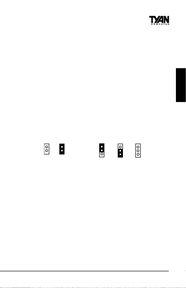
Quick References for Jumpers
In this manual, the terms closed and on are used when referring to jumpers (or jumper
pins) that are active; open and off are used when referring to jumpers (or jumper pins)
that are inactive. See the Figure 2-1 for examples of on and off pins and jumpers.
The square pin in the diagram is Pin 1.
Jumpers and pins are connected by slipping the blue plastic jumper connector overtop of
two adjacent jumper pins (indicated by 1-2 or 2-3). The metal rod
inside the plastic shell bridges the gap between the two pins, completing the circuit. See
Figure 2-2 for more examples of pin connections.
The tables and maps on the following pages will help you set the jumpers for CPU speed,
Infrared, and external connector pin assignments, among others. The miniature motherboard
maps will help you locate the jumpers on your board. A full-page map of the motherboard can
be found on the next two pages.
INSTALL
2 pin jumpers
off on
Figure 2-1
3 (or more) pin jumpers
1-2 2-3 open
1
2
3
1
2
3
Figure 2-2
1
2
3
Thunder 2500 S1867
11
Page 12
Chapter 2
Board Installation
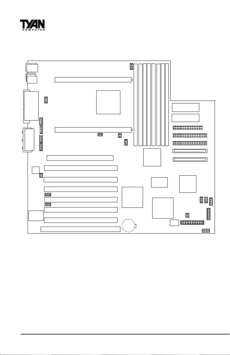
Map of Motherboard Jumpers
Mouse
Keyboard
USB2
USB1/
Ethernet
CPU slot 2 (Slot One type)
FAN5
1
DIMM bank 3
DIMM bank 2
DIMM bank 1
DIMM bank 0
Creative
ES1373
RCC-05B4
Winbond
ATX power supply
ATX power supply
Floppy connector
Secondary IDE connector
Primary IDE connector
Line Out
Line In
MIC
COM1
COM2
Game/
MIDI
Printer Port
1
1
1
1
Intel
82559
LAN
WOL
WOR
AMIBIOS
1
CD IN
(J15)
Video IN
(J14)
MONO IN
(J13)
MPEG IN
(J12)
1
JP9
FAN4
RCC-HE
CPU slot 1 (Slot One type)
JP3
AGP port
PCI slot 1
PCI slot 2
PCI slot 3
PCI slot 4
PCI slot 5
PCI slot 6
ISA slot 1
FAN3
JP1
1
RCC-C10B
3 volt
DIMM bank 3
DIMM bank 2
DIMM bank 1
DIMM bank 0
RCC-
MADP
The tiny 1s next to jumpers of 3 pins or more indicate the position of pin 1 for
that jumper.
Ultra2 SCSI Channel B
Ultra2 SCSI Channel A
LSI
53C896
FAN1
1
J29
1
CMOS
J32
1
JP33
FAN2
J24
1
J27
1
1
1
12
http://www.tyan.com
Page 13
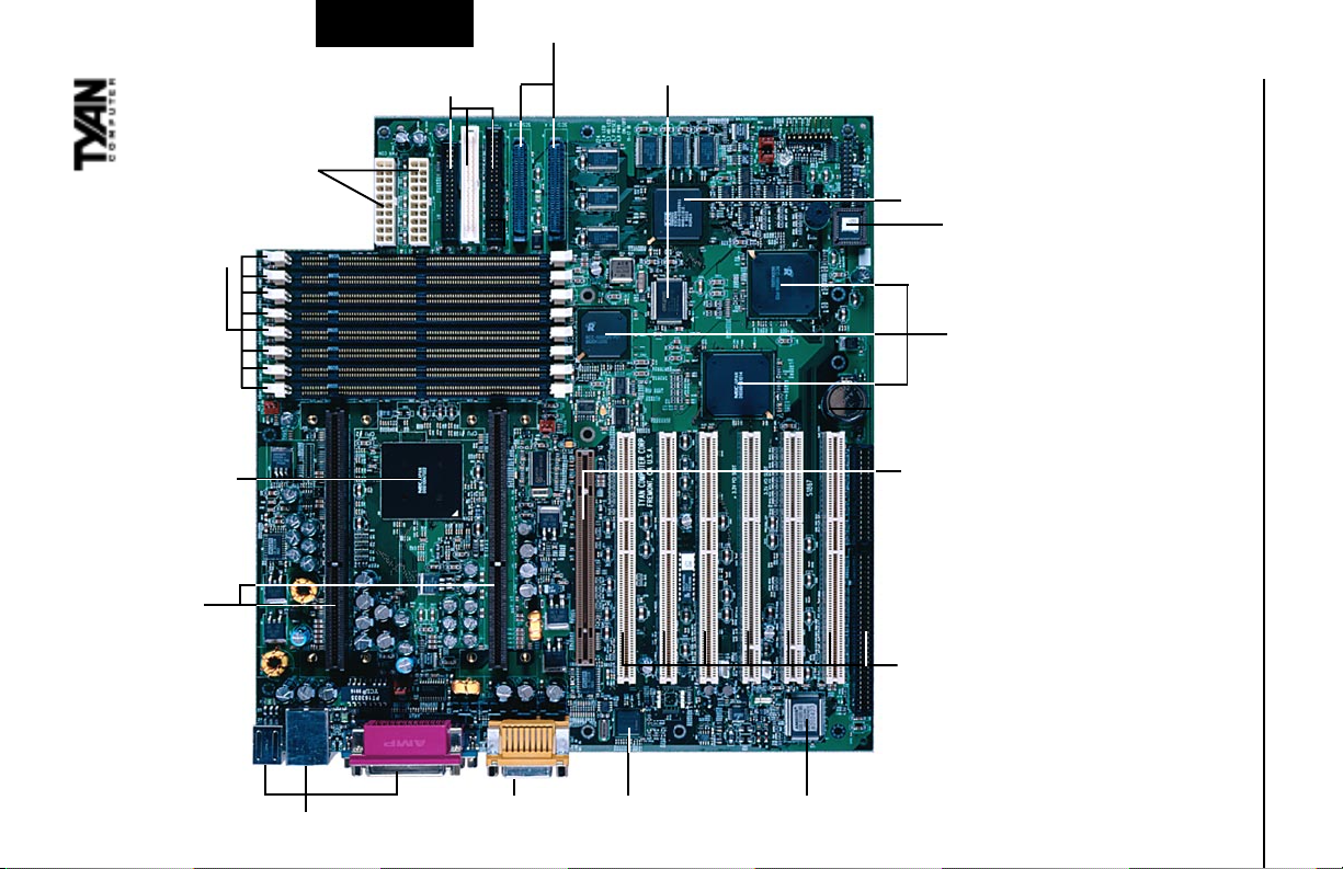
connectors
ATX Power supply
8 DIMM slots
ServerWorks ServerSet III HE
2 slot 1 connectors
INSTALL
IDE and Floppy
connectors
Ultra2/3 SCSI
channels
Creative
ES1373
AGP PRO port
1 ISA slot
SCSI LSI 53C896
or 53C1010
AMIBIOS
ServerWorks
ServerSet III HE
13
w/ LAN connector
Double row ATX connectors
MIC
Line In/ Out/
Game/MIDI/
Intel 82559 LAN
Super I/O
6 PCI slots/ 1 ISA
Thunder 2500 S1867
Page 14
Chapter 2
Board Installation
1. Setting Jumpers
1-A. Front Panel Assignment (Jumper J24)
VCC 12 Powe r LE D
HDD LED 34 Sleep LED
Ground 56Powe r On /O ff
Rese t 78 Ground
VCC 910 No Conn e ct
IR Receive 11 12 VCC
Ground 13 14 No Connect
IR Transmit 15 16 VCC
No Connect 17 18 No Connect
J24
12
Top
Bottom
34
56
78
901
1121
3141
5161
7181
Top Pin
Pin17
J24 Side View
Pin1
Bottom Pin
Pin2
*Power LED: For 2-pin: bicolor/single color LED - Use pins 2-4
For 3-pin: bicolor LED - Use Jumper J7
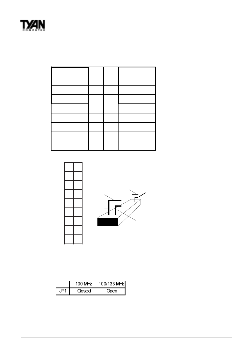
1-B. Front Side Bus Speed Select (Jumper JP1)
0+ ] 0+ ]
-3 &ORVHG 2SHQ
Jumper JP1 selects the Front Side Bus speed. When JP1 is closed, the FSB will run at 100
MHz only. Open jumper JP1 to allow both 133MHz and 100 MHz FSB support.
http://www.tyan.com
14
Page 15
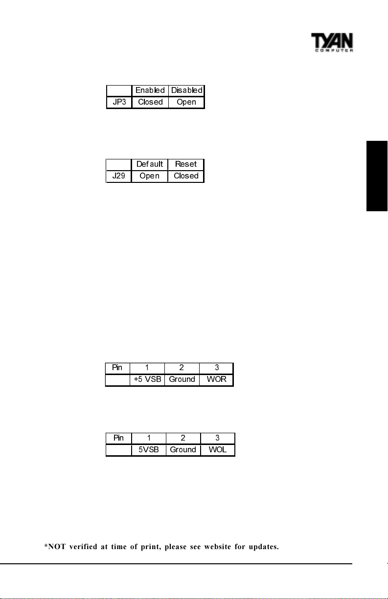
1-C. Spread Spectrum Enable/Disable (JP3)
(QDEOH G 'LVD EOH G
-3 &ORV H G 2SHQ
This jumper Enables/Disables the Spread Spectrum setting. With this setting enabled, it
reduces the amount of EMI emitted.
1-D. Reset CPU Speed and Safe Mode (Jumper J29)
'HI DXOW 5HVHW
- 2 SH Q &ORV H G
If you have been locked out of your system because you forgot your password or set the
CMOS incorrectly, follow the instructions below.
1. Power off the system
2. Close Juimper J29 (see page 12 for location of J29)
3. Power on the system, wait for at least 3 seconds, then power down
4. Open Jumper J29, then power on the system again.
By following this procedure, you will erase your password and reset CPU Speed.
1-E. Speaker Connector (Jumper J27)
The speaker should be connected to Jumper J27. As default, Jumper J27 closes pin 1 and 2
for use with the internal buzzer. Remove the jumper on pin 1 and 2 to connect an external
buzzer. The external buzzer must be a 4-pin header connecting to J27 from pin1 through
pin 4.
1-F. Wake-On Ring Connector (CON6)*
3LQ
96% *URXQG :25
* WOR connector at the time of print has not been tested.
1-G. Wake-On LAN Connector (CON5)*
3LQ
9 6% *URX QG :2/
INSTALL
1-H. Server Management Connector (J32)*
The EXTSMI (External System Management Interface) connector, jumper J38, is used by
some plug-in cards. Certain applications associated with these plug-in cards use the
interface for hardware control and queries.
*NOT verified at time of print, please see website for updates.
Thunder 2500 S1867
15
Page 16
Chapter 2
Board Installation
1-J. Fan1, Fan2, Fan3, Fan4, Fan5 - Pinout
- Fan3 connector corresponds to CPU 1 slot.
- Fan4 connector corresponds to CPU 2 slot.
- Fan1 / Fan2 are Chassis Fans
- Fan5 is an Auxhilary CPU fan header
Note: With Intels LANDesk system monitoring software, only two fans can be monitored at one time.
When using Intels LANDesk system management software, you may monitor the status
of the CPU Fans by connecting them to the Fan3 and/or Fan4 connectors. You will NOT
be able to monitor your CPU fan with the other Fan connectors.
1-L. Audio Connectors (J12, J13, J14, J15)
There are four black 4-pin connectors onboard which are used for various peripherals
audio signals. The digital signal that comes in through these connectors is directed through
the Ensoniq 1373 PCI sound Chip, and the digital signal is turned into an audio signal
which goes out through the speaker. The MPEG connector (J12) is for DVD cards, the
Mono connector (J13) is for Auxhilary audio inputs; the Video connector (J14) is for TV
cards and the CD-IN connector (J15) is for CD-ROMs.
1-M Enable/Disable LAN (JP9)
This jumper allows you to enable the onboard LAN function. Default is enabled (open).
(QDEOH 'LVDEOH
-32SHQ&ORVHG
1-N. Frontside USB Header (J33)*
Certain computer chassis allow for a front-end USB port connection. Therefore, this
board provides a front side USB header should you decide to set up a USB connector at the
front side of your computer.
Note: If you use J33, you will be unable to use the TOP USB port at the back of
!
the motherboard. Both J33 and USB1 share the same channel.
important!
Hardware Reset Switch Connector Installation
The Reset switch on your cases display panel provides you with the Hardware Reset
function, which is the same as power on/off. The system will do a cold start after the Reset
button is pushed.
CMOS RTC
The Real Time Clock (RTC) circuit, which provides the date and time for the system is
integrated into the ServerWorks ServerSet III HE chipset. If the external battery for the
RTC is low, you will most likely lose your BIOS settings. Normally the life span of an
external battery is 2 years. If yours is running low, you will need to replace it with a new
3V lithium battery (CR2032).
*NOT verified at time of print, please see website for updates.
16
http://www.tyan.com
Page 17

Flash EEPROM
The Thunder 2500 uses flash memory to store BIOS firmware. It can be updated as new
versions of the BIOS become available. You can upgrade your BIOS easily using the flash
utility (see page 56).
INSTALL
Thunder 2500 S1867
17
Page 18
Chapter 2
Board Installation
2. Mounting the Motherboard in the Chassis
Follow the instructions provided by the case manufacturer for proper installation
guidelines. TYAN recommends that you make use of all mounting holes to screw down the
motherboard. The adapter cards and the screws holding them down will keep your board
flat. The fastening screw should not short any of the traces on the motherboard. Make
certain that you do not overtighten the screw, as it will damage the motherboard and
possibly break internal traces in the surrounding area. The hole you should use is located at
the top-center of the board where the adapter cards are fastened to the case.
3. Installing Memory
Since TYAN boards are manufactured with performance in mind, you should use add-in
components that match. Some DIMM modules may seem to be high quality because of
name or feel but that does not guarantee real-world usability. Some cheaper or OEM
memory may have brand-name components, but they may contain inferior or substandard
parts which do not meet the critical tolerances our products require. Because of this, your
memory may not work correctly in a TYAN board though it may work well in a
competitors board. This is because many of our competitors do not adhere to the strict
tolerances required for high performance. If you buy a TYAN board, you are getting the
best system available. To make installation easy and trouble free, get high quality parts.
For a list of recommended memory vendors, please visit Tyans website at www.tyan.com go to the Memory Support area in the Support Section. The website memory compatibility lists include DIMMs that have proven to be very stable on our boards and perform
extremely well.
ATTENTION! ONLY REGISTERED DIMMs MAY BE USED ON
THUNDER 2500
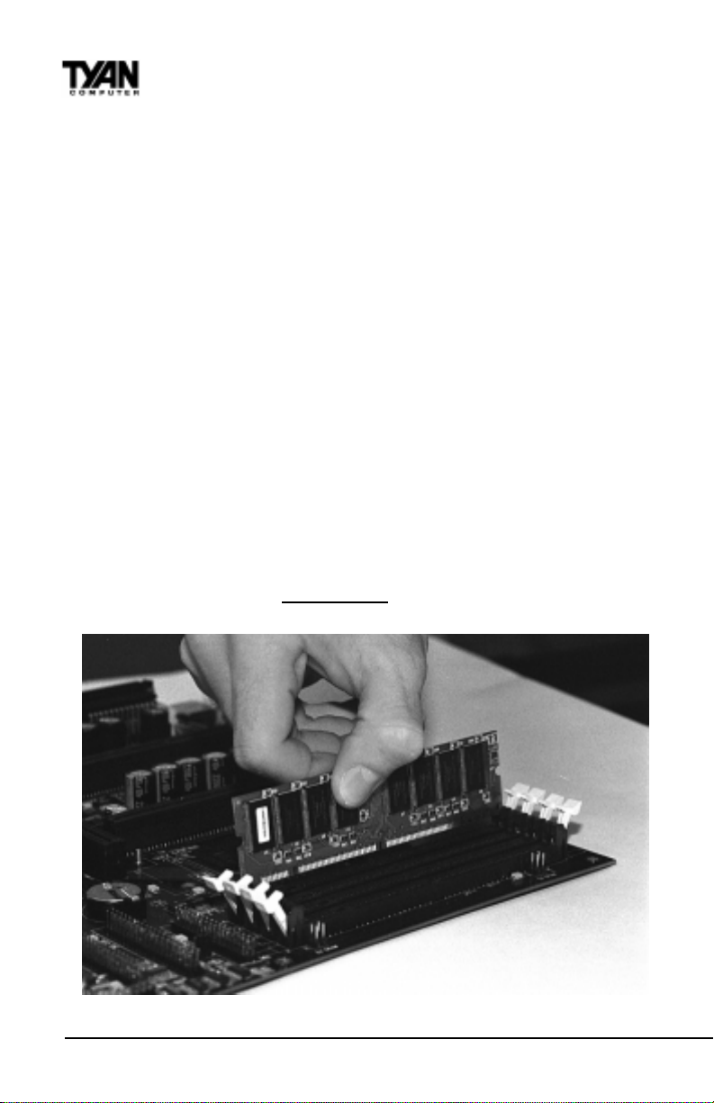
Figure 2-3
http://www.tyan.com
18
Page 19
To install your DIMMs, line your module up so that the pins fit into the slot. There is
only one way that your DIMM can fit properly. Make sure that the short row of pins is
lined up with the short gap in the DIMM slot. Figure 2-3 to the previous page shows how
to sit the DIMM into its slot. To insert the DIMM, push down vertically on the module
with even force, as shown in the photo. Do not shove one end in first; doing so will bend
the DIMM pins.
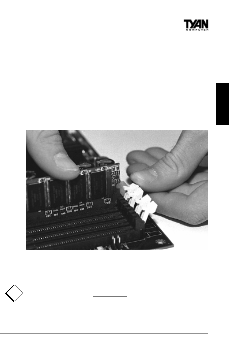
To lock the DIMM into place, push the plastic clips on either end of the slot onto the
notches at the ends of the DIMM (see Figure 2-4 below). In some cases, pushing the
memory module into the DIMM slot will move the plastic clips inward, automatically
locking the module into place. To remove your DIMM, simply pull the clips back, and
pull up on the module.
Place the DIMMs in an antistatic bag as soon as you remove them to avoid
static damage.
INSTALL
!
important!
Figure 2-4
The Thunder 2500 uses a 64-bit data path from memory to CPU and can accommodate up
to 8 GB of SDRAM. The 168-pin DIMMs (Dual In-line Memory Modules) must be of the
3.3V, buffered variety. The position of the notch in the SDRAM key position will tell
you whether or not a DIMM is buffered (see the Figure 2-5 on the following page). All
installed memory will be automatically detected, so there is no need to set any jumpers.
ATTENTION! ONLY REGISTERED DIMMs MAY BE USED ON
THUNDER 2500
Thunder 2500 S1867
19
Page 20
Chapter 2
Board Installation
EEPROM
RFU
Unbuffered
Buffered
Figure 2-5a
Some details of memory installation:
The mainboard supports registered 64MB, 128MB, 256MB, 512MB memory
modules; and supports 1024MB registered SDRAM DIMM modules.
PC100 / PC133 DIMMs may be used
The board supports registered memory chips ONLY. DO NOT mix registered and
non-registered memory chips on the motherboard. Memory modules must be of the
same brand and variety. DO NOT use different memory modules at the same time.
!
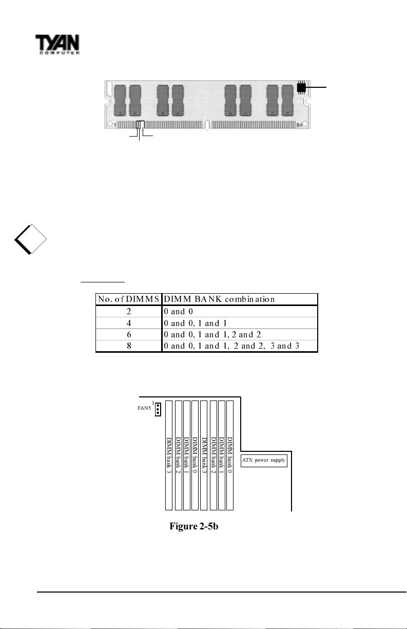
Attention: Due to specific memory population, the DIMM modules must be
important!
inserted as pairs. In order for the board to Post please install the DIMMs in the
combination shown below. All DIMM modules must be the same size and they
must be Registered DIMMs. See table below and Figure 2-5b for details.
1R R I',0 0 6 ',0 0 %$ 1.FRPELQDWLRQ
DQG
DQGDQG
DQGDQGDQG
DQGDQ G DQGDQG
See www.tyan.com for latest memory compatibility information.
1
FAN5
DIMM bank 0
DIMM bank 1
DIMM bank 2
DIMM bank 3
DIMM bank 3
Figure 2-5b
20
DIMM bank 0
DIMM bank 1
DIMM bank 2
ATX power supply
http://www.tyan.com
Page 21
4. Installing the CPU and Cooling Fan
Pentium II or Pentium III processors can be used on the Thunder 2500. Please refer to pages
14-17 for the correct CPU jumper settings for your board. Remember:
• The CPU is a sensitive electronic component and it can easily be damaged by static
electricity. Do not touch the CPU pins with your fingers.
• Before the CPU is installed, the motherboard must be placed on a
flat surface. You should be able to insert the CPU with minimal, but
firm pressure. Do not press down hard on the CPU.
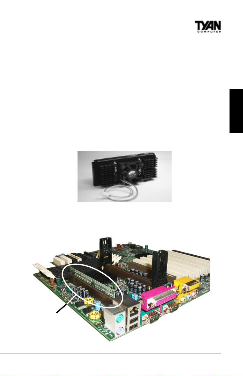
With CPUs reaching much higher clock frequencies, much more effecient cooling methods
must be used to prevent the CPU from overheating. The cooling fan is an important
component that is commonly neglected. Currently, one type of cooling mechanism is
produced for Pentium II / III processors. The active cooler is equipped with a cooling fan
and heatsink, allowing better air flow as well as heat dissipation for the CPU. (See Figure 26 below) The type of cooler used has no effect on performance, as long as the CPU fan is
properly connected to the CPU fan header on the motherboard.
Figure 2-6
Figure 2-7 below shows an overhead view of the retention braces positioned at both ends of
the CPU slot. Be sure to tighten the retention brace screws to secure them onto the
motherboard. The terminator card must be inserted into the vacant slot if only one CPU
is used.
INSTALL
Terminator Card
Thunder 2500 S1867
Figure 2-7
21
Page 22

Chapter 2
Board Installation
Figure 2-8
Carefully line up the pins of the CPU with the pins of the slot while placing the CPU
between the two retention braces (the CPU cooling fan should face away from the PCI
slots). Lower the CPU onto the motherboard (see Figure 2-8 above). Your CPU will be
firmly secured onto the motherboard once the retention braces snap into the sides of
the CPU. The installed CPU should look like Figure 2-9 below. Take the overhead clip
(See Figure 2-10 on the right) and insert the ends of the clip over the top of the side
braces.You will hear a click when the overhead clip is fitted securely into the side braces.
Finally, connect the CPU fan connector to the CPU fan header on the motherboard,
please see page 16 for details regarding the appropriate header for the CPU fan.
Figure 2-9
22
http://www.tyan.com
Page 23

Tab
Tab
Lowered lip
Make sure the lowered lip of the overhead clip is oriented away from the CPU
fan (see Figure 2-11 below).
Figure 2-10
INSTALL
Removing CPU
Figure 2-11
Removal of the CPU is basically the reverse order of the installation steps. First remove
the overhead clip. You need to push BOTH side tabs (see Figure 2-10 above) inwards in
the order to unlock it from the side braces. After the overhead clip is removed, remove
the CPU by gently bending the sides of the retention brace away from the CPU and slowly
pulling the CPU upwards. This may require careful firm tugs to pull the CPU out of its
slot.
Thunder 2500 S1867
23
Page 24

Chapter 2
Board Installation
5. Connecting IDE and Floppy Drives
The colored stripe on a ribbon cable should face toward the battery on the motherboard. In
Figure 2-12 below, you can see how the IDE cables should look when they are connected to
your hard drive. Notice how Pin 1 (denoted by a red stripe) is connected so that it is next to
the power connector of the drive. The primamry IDE connector is black; the secondary
IDE connector is white. If you are using a UDMA/66 cable, the blue end must connect to the
motherboard
Top
View
Figure 2-12
Side View
In most cases, this is the proper way of connecting your IDE cable to hard drive. Figure 2-13
on the following page shows the IDE cable properly connected to the motherboard. Contact
your hard disk drive manufacturer or documentation for more information.
Some symptoms of incorrectly installed HDDs are:
Hard disk drives are not auto-detected: may be a Master / Slave problem or a bad
IDE cable. Contact your vendor.
Hard Disk Drive Fail message at bootup: may be a bad cable or lack of power
going to the drive.
No video or beeps on bootup: usually means the cable is on backwards.
Hard drive lights are constantly on: bad IDE cable or defective drives/mother
board. Try another HDD.
Hard drives do not power up: check power cables and cabling. May also be a bad
power supply or IDE drive.
http://www.tyan.com
24
Page 25

Pin 1
Figure 2-13
Connecting Floppy Drives
Pin 1 on the floppy cable is usually denoted by a red or colored stripe down one side of the
cable (see Figure 2-14 below). Most of the current floppy drives on the market require that
the colored stripe be positioned so that it is right next to the power connector. In most cases,
there will be a key pin on the cable which will force you to connect the cable properly.
INSTALL
Thunder 2500 S1867
Figure 2-14
25
Page 26

Chapter 2
Board Installation
Drive A: is usually attached to the end of the cable with the twist in it. Drive B: is usually
connected to the middle of the cable. Refer to your installation instructions or call your
dealer if you are unsure about attaching floppy drives. Refer to Figure 2-14 for a detailed
anatomy of the floppy cable. Remember, you can only have 2 floppy drives connected at
any given time.
The color stripe on the cable should face toward the top of your chassis, or toward the big
white B printed on the motherboard. Please refer to your documentation for proper
installation.
Some symptoms of incorrectly installed floppies are:
Floppy drives are not detected: usually caused by faulty cables,
backward cables, or a bad floppy or motherboard. Try another single
floppy drive to verify the problem or try another cable. Also, check to
see if the onboard floppy is enabled in the BIOS.
Floppy Drive Fail message at bootup: the cable, floppy, or
motherboard may be faulty. Try another cable or floppy drive to
verify.
Light on the floppy is on constantly: a dead giveaway that the cable
is on backwards. Reverse the cable at the motherboard end and try
again.
6. Installing Add-on Cards
Thrre are certain rules you need to follow when plugging in a card. In order to assure
proper operation and a quick installation, adhere to these guidelines:
If you are going to install a PCI-Bus interface card on your system,
be aware that any one of the PCI slots can support a Master
or Slave device.
!
important!
NEVER force a card into a slot. If it doesnt fit, look at the socket
on the computer to make sure there are no wires or other
obstructions to the slot.
NER plug an ISA card into a PCI slot or a PCI card in an ISA
slot. You will void your warranty and damage your system board if
u do this.
When plugging the card in, especially when installing long cards,
try to push the entire card in at one time. Dont force one end of
the card into the socket first and then the other. This will create a
rocking motion between the card and the slot and it will damage the
pins within the socket.
Make sure that the cards are seated securely into the slots.
Before turning on the system, make sure no cards are touching.
If you follow these basic guidelines, there shouldnt be any problems with installation.
However, if you do encounter any problems, have a qualified professional install your cards
for you or contact your card manufacturer.
26
http://www.tyan.com
Page 27

!
important!
Remember, always read the manuals and installation notes that come with the adapter
cards. They contain important information which will help you install the components
right, the first time.
7. Connecting PS/2, USB, Serial & Parallel Devices
This board includes ports for USB, PS/2 mouse, and PS/2 keyboard devices. Note that, for
this board, the PS/2 mouse port is the upper PS/2 port, and the PS/2 keyboard port is the
lower PS/2 port.
The PS/2 connectors are probably quite familiar to you. The USB connectors, however,
may be foreign. The USB (Universal Serial Bus) is a versatile port. This one port type can
function as a serial, parallel, mouse, keyboard, or joystick port. It is fast enough to support
video transfer, and is capable of supporting up to 127 daisy-chained peripheral devices.
Connecting Com and Printer Ports
Warning: When plugging in your keyboard and mouse, or when plugging anything into a
serial or Com port, make sure that the power is off. Connecting these devices and ports
while the power is on is called hot plugging, and may damage your system.
Figure 2-15 below shows the ATX double row connectors on this board. The Com and
Printer ports, as well as the other ports, are labeled.
Note: Only TYAN cables will work on this motherboard. If you are using an existing case
with old cables, your system will not function properly. Use only TYAN-approved cables.
PS/2 mouse Ethernet LPT MIDI / Game Port
INSTALL
PS/2 keybrd USB O/1 COM1 Video-out Line-out Line-in Mic-in
Figure 2-15
Thunder 2500 S1867
27
Page 28

Chapter 2
Board Installation
8. Connecting the Power Supply
Figure 2-16 Figure 2-17
Tyan recommends using an ATX power supply that conforms to industry standard revision
2.01. The Thunder 2500 motherboard comes equipped with two onboard power connectors. Figure 2-16 above shows an ATX power connector. When plugging in the power
connector, make sure that the plastic clip on the power connector is aligned with the
plastic tab on the onboard connector (see Figure 2-17 above).
Make certain that you do not miss any pins because if you do, you will void your warranty
and cause damage to yourself or your motherboard when you turn the system on. After
connecting the power, make sure the connector is seated firmly into its socket so it will
not become loose or fall off when the computer is jostled or moved. NOTE: When
!
installing your power supply, make sure the power supply switch is turned Off.
important!
You may turn the switch back On once youve finished building your system.
You are done!
Other than checking the jumper settings and cable connections and putting the case back
on, you are done. Installing a new motherboard may sound difficult, but by following these
directions, you should have a fairly uneventful time installing our products. If you do
encounter problems, your dealer will be able to help you, or you can consult one of our
many technical support resources (see page 8).
*NOT verified at time of print, please see website for updates.
28
http://www.tyan.com
Page 29

Intel Ethernet Setup and Use
The Thunder 2500 S1867 has the Intel 82559 10/100 Ethernet chip onboard, which
makes setting up your Ethernet connection quite simple. The following installation and
configuration instructions are courtesy of Intel, and the copyright on the information
belongs to Intel Corporation. For more information, data sheets, white papers, or demos,
visit their networking web site at http://www.intel.com/network.
You can use your modem or Internet connection to download drivers, troubleshooting tips,
and more. When downloading new drivers, make sure the archive is for the PRO/100+
adapter (not PRO/100). This information can be found on Intels website, as well as their
FTP site and BBS service. You may find the driver in Tyans CD.
Connect the Network Cable.
Connect a single network cable to the PRO/100+ adapter. The cable will only fit one way.
For 100BASE-TX, your network cable must be category 5, twisted-pair wiring. If you plan
on running the adapter at 100 Mbps, it must be connected to a 100BASE-TX hub (not a
100BASE-T4 hub). For 10BASE-T, use category 3, 4, or 5 twisted-pair wiring.
100BASE-T Wiring: Twisted Pair Ethernet (TPE). Use category 5 cable and RJ-45
connector for this adapter. Do not use category 3 wiring at 100 Mbps. At 100 Mbps,
connect to a TX hub, not a T4 hub. Note: For more information on 100BASE-T wiring
requirements and limitations, see Fast Ethernet Wiring in this guide and refer to the
README files on the installation disk.
To configure the adapter, continue with the procedures specific to your operating system
on the pages which follow.
INSTALL
Enable Wake-on LAN Power Jumper (JP34) For Add-on Ethernet Cards only*
In order for the Wake On LAN (WOL) feature to work correctly, the adapter must be
connected to a continuous power source. This allows the PRO/100+ adapter to listen to
the network even when the computer is turned off. The WOL power connector (CON6) is
enabled when the jumper is connected or closed (ON). Warning: As always, turn off
!
and unplug power to the computer before setting the WOL jumper. The WOL
important!
connector on your motherboard is live when the computer is plugged in to a power outlet.
Failure to do so could damage the adapter or computer. Also, be sure that your ATX power
supply is 2.01 compliant or better. This level of quality is required because WOL requires
800 mAmps of 5V standby current. Due to power supply requirements, the ethernet add-
on card must have the Intel 82559 Chip for wake-up.
Using Wake-on LAN*
In order to use the onboard LAN wake-up feature, you must enable the LAN Wake-up for
Onboard LAN option in the Power Management Setup of the BIOS. The Wake-on LAN
feature operates according to a published specification. In simple terms, the specification
Thunder 2500 S1867
29
Page 30

Chapter 2
Board Installation
allows designers to build network adapters that are capable of listening to network
activity even when the computer is turned off. WOL adapters have a special low power
standby mode that is active when the rest of the computer is without power. The adapter
will respond to a special wake-up packet sent by another computer or network device.
Typically this wake-up packet causes the adapter to signal the computer to power up and
run a predefined program.
The wake up packet structure and behavior is defined in the WOL specification, available
from the website at http://www.us.pc.ibm.com/infobrf/iblan.html. See the Troubleshoot-
ing section on page 38 for Wake-on LAN troubleshooting tips.
Configuration and Drivers
The Ethernet driver can not be installed directly from the Tyan Driver CD. Before
installing the Intel 82559 Ethernet drivers, the complete LAN 82559 directory and all its
contents must first be copied from the Tyan Driver CD onto your hard drive. The 82559
driver can then be installed from your hard drive. Make sure that you are following the
proper instructions for your operating system (e.g. if you are using Windows 95 or 98, do
not follow the Windows NT instructions).
DOS Setup for Novell NetWare Clients
Automatic configuration
PCI computers automatically detect and configure PCI-compliant adapters while booting.
The Intel 82559-based Integrated Fast Ethernet For WfM adapter IRQ level and I/O
memory address are automatically set by the BIOS each time you start your computer.
Start your computer to automatically configure the adapter. Configuration is complete
when the DOS prompt appears. You can now continue with the procedure below.
Run Setup to install network drivers
Setup can automatically install NetWare DOS ODI client drivers for you or display a
README file with installation instructions for other NOS drivers.
1.
2.
1. If your computer already has network drivers installed, restart the computer
3.
procedure
without loading them. If the drivers are loaded from the AUTOEXEC.BAT or
CONFIG.SYS file, type REM in front of each line that loads a network driver.
Or, with DOS 6.x or later press 5 as DOS starts, to bypass the drivers.
2. Insert the Intel Configuration and Drivers floppy/CD in a drive, switch to
the appropriate drive/directory, and at the DOS prompt, type SETUP.
3. If you have more than one Intel PRO series PCI adapter in your computer,
an adapter selection menu appears on the screen. Select the adapter you
want by noting the Ethernet address. See Installing Multiple Adapters for
more information.
4. Select Automatic Setup from the Main menu. Then follow the instructions
on the screen. (If you want to test the adapter with a responder on the
network, see the next procedure.) Setup displays the adapters configuration, then runs
a series of diagnostic tests that makes sure the adapter and
network are functioning properly. If Setup finds a problem, it displays the
results and some possible solutions.
30
http://www.tyan.com
Page 31

5. When Setup finishes the tests, youll see the Install Network Drivers
screen.
6. Select the driver you want to install. Setup can install a NetWare client
driver for you. If youre installing other drivers, Setup displays a README
file with installation instructions. If you cant connect to a server, first try
the suggestions here, then turn to the Troubleshooting section on page 36.
Make sure youre using the drivers for this adapter. The driver filename
contains the letter B (for example, E100BODI.COM).
If youre replacing an existing adapter, make sure the LINK statement in
your NET.CFG is correct for the new adapter. For example, the LINK
statement for a NetWare client should be: LINK DRIVER E100BODI
Verify that the frame type in your NET.CFG file matches your network.
If setting up a server, check your LOAD and BIND statements.
Test the adapter by running diagnostics in Setup. Additional testing is available by using
a responder (see next page).
Check the README files.
Responder testing on the network (optional)
Setup can test the adapter more thoroughly if you have a responder on the network while
running the tests.
1. Go to a computer on the network with any EtherExpress adapter installed (except
EtherExpress 32 or EtherExpress 16 MCA).
2. Run the appropriate configuration program for the installed adapter and set it up as a
responder.
3. Return to the computer with the new adapter. Run Setup and make the new adapter a
sender. Test the adapter.
Windows NT Server or Workstation
Automatic configuration
PCI computers automatically detect and configure PCI-compliant adapters while booting.
The Intel 82559-based Integrated Fast Ethernet For WfM adapter IRQ level and I/O
address are automatically set by the BIOS each time you start your computer. Start your
computer to automatically configure the adapter. Configuration is complete when
Windows NT starts or the DOS prompt appears.
INSTALL
Install network drivers - Windows NT Version 4.0 only
We recommend that you install the network drivers for the onboard Intel 82559 network
adapter after NT has been installed. In other words, do not let NT auto-detect the onboard
network card during the installation. The following steps will guide you through the
installation procedure. You will need to have the Tyan driver CD and the NT 4.0 CD for
this procedure.
Thunder 2500 S1867
31
Page 32

Chapter 2
Board Installation
1.
1. Boot NT 4.0
2.
2. Get the Tyan Driver CD and copy the Intel LAN drivers to a directory on
3.
procedure
your hard disk drive.
3. Double-click the Network icon in the Control Panel
4. Click the Adapters tab in the window that appears.
5. Click Add. A list of adapters appears.
6. Select the Have Disk icon and point it to the directory that you created on
your hard drive in step 2.
7. You will see Intel PRO PCI Adapter. Click OK.
8. Follow the NT prompts to complete the installation. (This will require the NT
4.0 CD)
9. Click OK in the main PROSet window to return to Windows NT.
10. Click close to finish.
11. Restart Windows NT when prompted.
12. To verify proper installation of the adapter, go to the Control Panel, doubleclick the Network icon, select the Adapters tab. You should see the name
Intel (R) PRO/100+ Management Adapter in the network adapter window.
To install multiple adapters, repeat this procedure for each new adapter. See Installing
Multiple Adapters for specific information. To run the PROSet software at any time,
double-click the Intel PROSet icon in the Control Panel or click the Adapter Properties
button.
1.
2.
Windows 98
3.
procedure
Install Network Drivers from CD
1. After completion of Windows 98 installation, you will have to remove the
PCI Ethernet Controller under the Device Manager menu. (Go to Control
Panel and then to Device Manager. Under the Other Devices section, choose
PCI Ethernet Controller and click Remove.)
2. Reboot the system. An Add New Hardware Wizard dialog box should
appear indicating that a PCI Ethernet Controller has been found.
3. Click the Next button. Then select the Search for the best driver for your
device option. (Make sure your Tyan Driver CD has been inserted)
4. Select the Specify a location option. At the command prompt, type
D:\LAN82559 (assuming D: is your CD-ROM drive)
5. Click Next. The Intel (R) Pro/100+ Management Adapter should appear.
Click Next again.
6. Continue installation process by following the Windows instructions.
7. To check for proper installation, the Intel Pro/100+ Management Adapter
should be found under System Properties in the Device Manager menu
* In general, Windows 98 will automatically install the network drivers
NetWare Server, Client 32, UNIX, OS/2, Banyan, and Other
Operating Systems
For these, refer to our online documents. On a DOS computer, view the appropriate
README file for information on installing your network driver. To view the README
http://www.tyan.com
32
Page 33

files, insert the Intel Configuration and Drivers disk into a drive, switch to that drive, and
type: SETUP /README. Look through the selection called Installing Intel PRO/100+
Management Adapter Drivers for the operating system you need.
Installing Multiple Adapters
All users: The adapters 12-digit, hexadecimal Ethernet address is on a sticker on the
motherboard near the LAN controller chip. The Ethernet address is sometimes called the
node address or the MAC address. Note that the PCI slot number may not correspond with
the physical connector in your computer.
NetWare users: The server drivers use the PCI slot number to identify each installed
adapter. You can correlate the PCI slot number to the adapter by using the Ethernet
address that is printed on a label on the adapter. Run Setup from the Intel disk to view the
Ethernet address and slot number for each installed adapter. For more information, see the
README files. NetWare 4.11 server installations use unique slot numbers that are assigned
during sever setup.
Windows NT and Windows 95/98 users: Repeat the configuration procedure for each
adapter you want to install (add only one adapter at a time). In Windows NT, be sure to
click the Show all PRO Adapters box in the Configuration window. See the README file
for more information.
Select Duplex Mode (optional)
Duplexing is a performance option that lets you choose how the adapter sends and
receives data packets over the network. The PRO/100+ adapter can operate at full duplex
only when connected to a full duplex 10BASE-T, 100BASE-TX switching hub, or another
full duplex adapter. To summarize:
Auto (requires a full duplex adapter or switching hub with auto-negotiation
capability). The adapter negotiates with the hub to send and receive
packets at the highest rate. This is the default setting. If the hub does not
provide auto-negotiation, the adapter runs at half duplex.
Full duplex (requires a full duplex switching hub or adapter). The adapter can send and
receive packets at the same time. This mode can increase adapter performance capabili
ty. If the full duplex hub provides auto-negotiation, the adapter runs at full duplex. If
the full duplex hub does not provide auto-negotiation, you need to set the adapter
duplex mode manually. (see following paragraphs)
Half duplex. The adapter performs one operation at a time; it either sends or
receives.
Note: If your hub is running at 100 Mbps and half duplex, your potential bandwidth is
higher than if you run at 10 Mbps and full duplex.
INSTALL
Thunder 2500 S1867
33
Page 34

Chapter 2
Board Installation
Troubleshooting
If the adapter cant connect to the network:
• Make sure the cable is installed properly. The network cable must be securely attached
at both RJ-45 connections (adapter and hub). If the cable is attached but the problem
persists, try a different cable. The maximum allowable distance from adapter to hub is
100 meters. If youre directly connecting two computers (no hub), use a crossover
cable. Most hubs require a straight-through cable, while most switches require a
crossover cable (see your hub or switch documentation to verify). See the Cabling
Information README file for more information on crossover cables.
• Check the LED lights on the adapter. The onboard cable connector has
two diagnostic LEDs. These lights help indicate if theres a problem with the
connector, cable, or hub. The table below describes the LEDs, and the drawing on the
next page shows their location.
DELnoitacidnIgninaeM
KNL nO
)neerg( ffO
001 nO.spbM001tagnitareponoitcennockrowteN
)wolley( ffO.spbM01tagnitareponoitcennockrowteN
.melborpnoitarugifnocrevirdaevahuoyro
;noitcennocadegdelwonkcaevahbuhdnaretpadaehT
.doogsiretpadadnabuhehtneewtebknileht
,ytluafsiretpadadnabuhehtneewtebnoitcennocelbacehT
• Make sure youre using the correct drivers. Make sure youre using the drivers that
come with this adapter. Drivers that support previous versions of the Intel PRO/100+
Management Adapter do not support this version of the adapter.
100 Mbps LED
Y
• Make sure the hub port and the adapter have the same duplex setting. If you
configured the adapter for full duplex, make sure the hub port is also configured for
full duplex. Setting the wrong duplex mode can degrade performance, cause data loss,
or result in lost connections.
Link LED
G
http://www.tyan.com
34
Page 35

Testing the adapter
Test the adapter by running Intel diagnostics. For DOS or Windows 3.1 computers, run
Setup on the Intel Drivers and Configuration disk. For Windows NT and Windows 95 run
Intel PROSet by double-clicking the Intel PROSet Icon in the Control Panel. Click Help
from the main PROSet window to get complete diagnostics information and instructions.
Common problems and solutions
SETUP.EXE reports the adapter is Not enabled by BIOS.
The PCI BIOS isnt configuring the adapter correctly.
The computer hangs when the drivers are loaded.
Change the PCI BIOS interrupt settings.
If you are using EMM386, it must be version 4.49 or newer (this version
ships with MS-DOS 6.22 or newer).
Diagnostics pass, but the connection fails or errors occur.
At 100 Mbps use category 5 wiring and make sure the network cable is
securely attached.
For NetWare clients, make sure you specify the correct frame type in our
NET.CFG file.
Make sure the duplex mode setting on the adapter matches the setting on
the hub.
At 100 Mbps, connect to a 100BASE-TX hub only (not T4).
The LNK LED doesnt light.
Make sure youve loaded the network drivers.
Check all connections at the adapter and the hub.
Try another port on the hub.
Make sure the duplex mode setting on the adapter matches the setting on
the hub.
Make sure you have the correct type of cable between the adapter and the
hub. 100 BASE-TX requires two pairs. Some hubs require a crossover cable
while others require a straight-through cable. See the Cabling README file
for more information on cabling.
INSTALL
The adapter stopped working when another adapter was added to the computer.
Make sure the cable is connected to the EtherExpress PRO/100 TX PCI
adapter.
Make sure your PCI BIOS is current.
Make sure the other adapter supports shared interrupts. Also, make sure
your operating system supports shared interrupts OS/2 doesnt.
Try reseating the newest adapter.
The adapter stopped working without apparent cause.
Try reseating the adapter first, then try a different slot if necessary.
The network driver files may be corrupt or deleted. Delete and then reinstall
the drivers.
Try a different PRO/100 TX PCI adapter.
Run the diagnostics.
Thunder 2500 S1867
35
Page 36

Chapter 2
Board Installation
The Wake-on LAN feature is not working.
Make sure the WOL cable is attached and power is applied to the computer.
Check the BIOS for its WOL setting. Some computers may need to be
configured to WOL.
Make sure the network cable is fully attached to the adapter.
Link LED does not light when power is connected.
Make sure WOL cable is attached and power is applied to computer.
Make sure network cable is attached at both ends.
Technical Information
Fast Ethernet Wiring
100BASE-TX Specification: The 100BASE-TX specification supports 100 Mbps
transmission over two pairs of category 5 twisted-pair Ethernet (TPE) wiring. One pair is
for transmit operations and the other for receive operations. Segment lengths are limited
to 100 meters with 100BASE-TX for signal timing reasons. This complies with the EIA
568 wiring standard.
Fast Ethernet Hub and Switches
The two basic types of hubs are shared hubs and switching hubs. Intel PRO/100+ adapters
can be used with either type of hub for 10 Mbps. At 100 Mbps, a TX hub or switch is
required.
Shared hubs
In a shared network environment, computers are connected to hubs called repeaters. All
ports of the repeater hub share a fixed amount of bandwidth, or data capacity. On a 100
Mbps shared hub, all nodes on the hub must share the 100 Mbps of bandwidth. As stations
are added to the hub, the effective band-width available to any individual station gets
smaller. Shared hubs do not support full duplex.
Think of a shared repeater hub as a single-lane highway that everyone shares. As the
number of vehicles on the highway increases, the traffic becomes congested and transit
time increases for individual cars.
On a shared hub all nodes must operate at the same speed, either 10 Mbps or 100 Mbps.
Fast Ethernet repeaters provide 100 Mbps of available bandwidth, ten times more than
whats available with a 10BASE-T repeater.
Repeaters use a well-established, uncomplicated design, making them highly cost effective
for connecting PCs within a workgroup. These are the most common type of Ethernet
hubs in the installed base.
Switching hubs
In a switched network environment, each port gets a fixed, dedicated amount of bandwidth.
In the highway scenario, each car has its own lane on a multi-lane highway and there is no
sharing.
In a switched environment, data is sent only to the port that leads to the proper destination station. Network bandwidth is not shared among all stations, and each new station
added to the hub gets access to the full bandwidth of the network.
http://www.tyan.com
36
Page 37

If a new user is added to a 100 Mbps switching hub, the new station receives its own
dedicated 100 Mbps link and doesnt impact the 100 Mbps bandwidth of another station.
Switching hubs can effectively increase the overall bandwidth available on the network,
significantly improving performance. Switching hubs can also support full duplex.
For more information on Fast Ethernet, visit the Network Products website (http://
www.intel.com/network).
Creative Labs Sound Drivers Installation Note
For S1867 Win NT 4.0 / Win98
Creative Labs ES1373 PCI Sound Setup
Note: This note assumes drive D: for your CDROM drive.
1.
2.
1) Go to the following directory path:
3.
procedure
D:\Audio\S1867\drivers\setup\english
2) Select (double-click) sbsetup.exe - Setup window will appear with Sound
Blaster Setup Options. The two options are Remove Only and Remove
and Install Software. The default setting is Remove and Install Software.
Use the default setting and click Next.
3) Click Next again. The installation will begin and autodetection of hard
ware and drivers will follow.
4) Click the Finish button and reboot the computer.
Frequently Asked Questions
Q: My system sometimes has no display. How should I check the system?
A: Check to see if the DIMM is REGISTERED. Also, the first thing to do is to check and
see if you have any device conflict in I/O address, IRQ, or DMA. If you are using Windows
95/98, the Device Manager is a good place to start. Please consult your operating system
manual for details. Second of all, slowing down the memory timing in the BIOSs chipset
setup section will help the situation, as well. Many memory modules are not suitable for
high performance systems and are probably the main source of your problem.
INSTALL
168-pin Registered DIMM
Q: Why dont I get a display after I put in my old DIMM module?
A: The SeverSet HE chipset requires the memory manufacturer to program an EEPROM
chip with SPD (Serial Presence Detection) on the module in order for the BIOS to
program the chipsets timing registers properly. Your DIMM may not have the EEPROM
chip on the module, or the EEPROM may not contain the correct program. Make sure
that the DIMM is Registered.
Thunder 2500 S1867
37
Page 38

Chapter 2
Board Installation
Q: Can I use EDO DIMMs on this motherboard?
A: No. The ServerWorks ServerSet does not support EDO memory.
Q: What is AGP?
A: AGP (Accelerated Graphics Port) is a new bus architecture for 3D graphics. The AGP
slot eliminates the PCI bandwidth bottleneck by bypassing the PCI interface and accessing
the system memory directly. Currently, the AGP supports 1X and 2X modes, which yield
bandwidths of 266MB/s (at 33MHz bus speed) and 533MB/s (at 66MHz bus speed),
respectively. Compare this with the mere 132MB/s (at 33MHz bus speed) that you get
from the PCI bus.
Q: Does my operating system support AGP?
A: Currently, only Windows 98 and Windows 2000 will have built-in support for AGP.
Some AGP cards require Windows 95 OSR2.1 or a special driver from
Intel. Please check with your graphics vendor for more details.
Q: How do I install the onboard NIC drivers for WinNT 4.0?
A: The Ethernet driver can not be installed directly from the Tyan Driver CD. Before
installing the Intel 82559 Ethernet drivers, the complete 82559 directory and ALL its
components must first be copied from the Tyan CD onto your hard
drive. The 82559 installation program can then be copied normally from your hard drive.
Q: How can I disable the keyboard detection in the BIOS?
A: You need to enable the Quick Boot option in CMOS - then the BIOS will not check for
a keyboard.
Q: I cannot install Windows NT when I use an LS/120-type floppy disk drive. What
should I do?
A: SYMPTOM - When you are trying to install Windows NT, you may
experience any of the following symptoms:
1) When you boot from the installation disks, the following error message
may be displayed when disk 2 is inserted:
Stop 0x0000007B Inaccessible Boot Device
(0xFF109C50, 0x00000000, 0x00000000, 0x00000000)
2) When you are attempting to create a set of installation disks using the
WINNT /ox or WINNT32 /ox command, the following error message may be
displayed:
This floppy disk is not formatted as high-density, not formatted
with a standard Windows NT or MS-DOS format, or is corrupted.
Setup is unable to use this disk.
CAUSE OF THE PROBLEM: You are using a LS/120-type floppy disk drive.
RESOLUTION - To work around this issue, install Windows NT Workstation with the
/b switch. This causes Windows NT Workstation Setup to run
without requiring the installation disks.
http://www.tyan.com
38
Page 39

INSTALL
39
If you are using the S1867 or are installing with LSI Symbios 53C896 with
53C896 or 53C1010 chip then you must install NT 4.0 with a standard 1.44MB floppy
disk.
Q: Where can I get Intel PRO/100+ Management Adapter drivers?
A: You will find the drivers located in the Tyan Drivers CD under the
subdirectory LAN82559. Please note: You must use the drivers provided
in the Tyan CD only. These drivers have been tested and approved by Tyan engineering.
Q: Why does my Intel Ethernet work only intermittently?
A: The Inter Ethernet only operates under standby current; therefore, your
power supply must be ATX 2.01 Compliant with a minimum SB5V current of
750mA.
Q: Why does my keyboard LED remain on after the system is turned off?
A: This situation is most likely caused by the enabling of Keyboard Wake-Up
Function (under the Peripheral Setup) in the BIOS. When enabled, the
motherboard would provide a standby voltage to the keyboard. This would
subsequently cause the LED to remain on.
Thunder 2500 S1867
Page 40

chapter 3
BIOS Configuration
Introduction to Setup
This manual describes the PhoenixBIOS Setup program. The Setup program lets you
modify basic system configuration settings. The settings are then stored in a dedicated
battery-backed memory, called NVRAM, that retains the information when the power is
turned off.
The PhoenixBIOS in your computer is a customized version of an industry-standard BIOS
for IBM PC ATcompatible personal computers. It supports Intel x86 and compatible
processors. The BIOS provides critical low-level support for the system central processing,
memory, and I/O subsystems.
The Phoenix BIOS has been customized by adding important, but non-standard features
such as virus and password protection, power management, and detailed fine-tuning of the
chipset controlling the system. The rest of this manual is intended to guide you through
the process of configuring your system using Setup.
The BIOS section of the manual is subject to change without
!
important!
notice and is provided here for reference purposes only. The
settings and configurations of the BIOS are current at the time
of print, and therefore they may not be exactly the same as that
displayed on your screen.
40
http://www.tyan.com
Page 41

The PhoenixBIOS Setup screen is shown below.
PhoenixBIOS Setup Utility
Main Advanced Security Misc. Boot Exit
System Time: [04:05:06] Item Specific Help
System Date: [01/11/2000]
Processor Speed [800 Mhz] <Enter> selects field
Front Side Bus: [100 Mhz]
Legacy Diskette A: [1.44/1.25 MB 3½]
Legacy Diskette B: [Disabled]
w
HDD Configuration
w
Keyboard Features
PS/2 Mouse [Auto Detect]
System Memory 640KB
Extended Memory 1024MB
w
Memory Cache
<Tab>, <Shift-Tab, or
BIOS
F1 Help
Esc Exit
↑↓ Select Item +/- Change Values F9 Setup Defaults
← Select Menu Enter Select Sub-Menu F10 Save and Exit
w
You can select a Setup option by using the following keyboard keys:
.H\ )XQFWLRQ
&KD QJ H 9DOX HV
$UURZNH\V &KDQJHVVHOHFWLRQVZLWKLQDER[
(QWHU 6HOHFW6XEPHQXLWHP
) +HOS
) 6HWXS'HIDXOWV
) 6DYHDQG([LW
(V F ([LW
The pages which follow contain explanations of the settings for the PheonixBIOS Setup
menus. Drawings have been included for ease of reference. Overall, the PhoenixBIOS
Setup program is easy to use, and fairly intuitive. Note that the graphics in the manual are
simpler than those that appear on your screen.
Thunder 2500 S1867
41
Page 42

Chapter 3
BIOS Configuration
Main Setup
Select the PhoenixBIOS Setup options below by choosing Main Setup from the
PhoenixBIOS main menu. The Standard Setup menu screen is shown below.
PhoenixBIOS Setup Utility
Main Advanced Security Misc. Boot Exit
System Time: [04:05:06] Item Specific Help
System Date: [01/11/2000]
Processor Speed [800 Mhz] <Enter> selects field
Front Side Bus: [100 Mhz]
Legacy Diskette A: [1.44/1.25 MB 3½]
Legacy Diskette B: [Disabled]
w
HDD Configuration
w
Keyboard Features
PS/2 Mouse [Auto Detect]
System Memory 640KB
Extended Memory 1024MB
w
Memory Cache
<Tab>, <Shift-Tab, or
F1 Help
Esc Exit
↑↓ Select Item +/- Change Values F9 Setup Defaults
← Select Menu Enter Select Sub-Menu F10 Save and Exit
w
System Date/Time
You can type the date and time in directly, or select the portion of the date or time that
you want to modify and adjust it using the +/− keys. The clock runs on a 24-hour cycle
(i.e. 1:00 PM is 13:00).
Processor Speed
Specifies the processor speed. Setting this value to a frequence higher than its rated value
can damage the processor. Setting will return to Safe mode after BIOS is reset.
Legacy Diskette A: and B:
Move the cursor to these fields via the arrow keys and select the floppy type. The settings
are 360KB 5¼ inch, 1.2 MB 5¼ inch, 720KB 3½ inch, 1.44MB 3½ inch, or 2.88MB 3½
inch. If you are not sure what type of floppy drive you have, consult the documentation
that came with your drive.
http://www.tyan.com
42
Page 43

HDD Configuration
Select this option to configure various drives including HDD and CDROMs, a picture of
this setup screen is featured on the follwing page. Select the correct device you need to
configure (eg. Primary Master or Secondary Slave) using the up and down arrow keys and
push the <Enter> key to enter the device setup.
PhoenixBIOS Setup Utility
Main
HDD Configuration Item Specific Help
w
Primary Master [<hard drive 1 name>]
w
Primary Slave [<hard drive 2 name>]
w
Secondary Master [<CDROM name>]
w
Secondary Slave [none]
IDE Bus Master DMA [Enabled]
Large Disk access mode: [DOS]
F1 Help ↑↓ Select Item +/- Change Values F9 Setup Defaults
Esc Exit
← Select Menu Enter Select Sub-Menu F10 Save and Exit
w
1- Primary / Secondary Master / Slave
Once the correct IDE device has been selected, a new menu will appear allowing the user
to adjust different varibles for this drive. By Default, the setting for all the devices is Auto.
If the settings do not appear to be correct, or you would like to adjust the default settings,
then the Type setting must be adjusted to [User], [CD-ROM], [IDE Removable] or
[ATAPI Removable]. Below is a listing of the device parameters within this section. For
User Configuration, both section a.) and b.) must be competed.
a.)User Configuration (Hard drive configuration):
retemaraPnoitpircseD
epyT
srednilyC.evirdksidehtnisrednilycforebmunehT
sdaeH.sdaehforebmunehT
srotceS
eziS
.)sepytevirdfoelbatarofegaptxeneht
.kcartrep
.)rotcesrepsetyb(215semit
ees(sretemarapnoitacifitnediniatrechtiwevirdarofrebmunehT
repsrotces71evahsevirdMFM.kcartrepsrotcesforebmunehT
43evahsevirdIDSE.kcartrepsrotces62evahsevirdLLR.kcart
srotceseromneveevahsevirdEDIdnaISCS.kcartrepsrotces
semitsdaehforebmunehtsievirdehtfoyticapacdettamrofehT
kcartrepsrotcesforebmunehtsemitsrednilycforebmuneht
BIOS
Thunder 2500 S1867
43
Page 44

Chapter 3
BIOS Configuration
b.) CD-ROM, IDE and ATAPI Removable Configuration:
retemaraPnoitpircseD
rotceS-itluM
srefsnarT
lortnoCedoMABL
O/ItiB23 .srefsnartatadEDItib23selbasiDroselbanEgnittessihT
.deireuq
rotceselpitlumrofkcolbrepsrotcesforebmunehtyficepS
nehwsnruterksidehtfoezisehtotsrefer"XAM".srefsnart
.srotceSdnasdaeH,srednilyCfoecalp
nidesuebotgnisserddAkcolBlacigoLsesuacABLgnilbanE
!
important!
edoMrefsnarT
edoMAMDartlU
.edomrefsnartmumitpoehttcelesotevird
2- IDE Bus Master DMA
Controls whether the BIOS prograoms the IDE controller for DMA Bus Mastering
Operation. Default is Enabled.
3- Large Disk Access Mode
If the intended operating system for this product is DOS or a deriative of DOS such as
Windows 9X or NT, then select the DOS option. If the intended operating system is
something besides DOS such as Unix ,Novell or Linux, then select Other.
Keyboard Features
retemaraPnoitpircseD
kcoLmuN.kcoLmuNrofetatsno-rewoPstceleS .otuAsitluafeD
kcilCyeK.kcilcyeKselbanE .delbasiDsitluafeD
-otuadraobyeK
etartaeper
-otuadraobyeK
yaledtaeper
.etartaeperyekstceleS .ces/03sitluafeD
.taeperyekerofebyaledstceleS .ces2/1sitluafeD
PS/2 Mouse
Disabled prevents any installed PS/2 mouse from functioning, but frees up IRQ 12.
Enabled forces the PS/2 mouse port to be enabled regardless if a mouse is present. AutoDetect will enable the PS/2 mouse only if present. Default is Auto-Detect.
ehtepytotuA.evirdehtmorf/otatadgnivomrofdohtemehttceleS
ehtmorf/otatadgnivomrofdesuedomAMDartlUehtstceleS
.edomrefsnartmumitpoehttcelesotevirdehtepytotuA.evird
44
http://www.tyan.com
Page 45

Memory Cache
retemaraPnoitpircseD
ehcaCyromeMD.ehcacyromemehtfosetatsehtsteS .delbanesitluafe
SOIBmetsySehcaC
aera
SOIBoediVehcaC
aera
k215-0esaBehcaC.yromemesabk215fognihcacslortnoC .kcaBetirWsitluafeD
-k215esaBehcaC
k046
dednetxEehcaC
aerAyromeM
FFFFA-0000AehcaC
FFFE-00CEhguorht
.yrassecener .delbasiDsitluafeD
.kcaBetirWsitluafeD
.derongierasetirW-tcetorP
.aeraSOIBmetsysfognihcacslortnoC .delbanEsitluafeD
.aeraSOIBoedivfognihcacslortnoC .tcetorPeirWsitluafeD
.k046-k215fognihcaCslortnoC .kcaBetirWsitluafeD
.dehcactonsikcolbsihT-delbaiD
Advanced Setup
Setting items on this menu to incorrect values may cause your system to
!
malfunction. It is suggested to use the Manufactuers Defaults.
important!
PhoenixBIOS Setup Utility
Advanced
Item Specific Help
.BMenoevobayromemmetsysfognihcaCslortnoC
.denibmoCetirWevitalucepSdehcacnU-CWSU
etirWecnotayromemniamottnesdnadehcacerasetirW-hguorhtetirW
litnuyromemniamottnestontubdehcacerasetirW-kcaBetirW
BIOS
Installed O/S [Other]
Reset Configuration Data [No]
Extended Memory Test [Enabled]
CPU-to-PCI Deferred Cycles [Enabled]
w
PCI Configuration
F1 Help ↑↓ Select Item +/- Change Values F9 Setup Defaults
Esc Exit
Thunder 2500 S1867
← Select Menu Enter Select Sub-Menu F10 Save and Exit
w
45
Page 46

Chapter 3
BIOS Configuration
Advanced Features Setup
retemaraPnoitpircseD
S/OdellatsnI
noitarugifnoCteseR
ataD
tseTyromeMdednetxE
derrefeDICPot-UPC
selcyC
noitarugifnoCICP(.secivedICPerugifnocotsuneMnoitiddA )wolebnoitcesoteunitnoC(
PCI Configuration
PhoenixBIOS Setup Utility
Advanced
w
Network
w
SCSI
w
Sound
w
USB
w
AGP Device
w
PCI Slot 1
w
PCI Slot 2
w
PCI Slot 3
w
PCI Slot 4
w
PCI Slot 5
w
PCI Slot 6
ISA Graphics device Installed: [NO]
w
PCI/PNP UMB IRQ Region Exclusion
w
PCI/PNP ISA IRQ Resource Exclusion
PCI Configuration Item Specific Help
.oNsitluafeD
.TSOP .delbanEsitluafeD
.roivahebdetcepxenuyalpsid rehtOsitluafeD
.msinahcemyrterehtesulliwtespihceht,delbasiD .delbanEsitluafeD
esulliwuoyhcihwmetsysruoynodelllatsnimetsysgnitarepoehttceleS
otsmetsysgnitarepoemosesuacgnittestcerrocninA:etoN.ylnommoctsom
.ataDnoitarugifnoCmetsySdednetxEraelcottnawuoyfi'seY'tceleS
gnirudyromemdednetxeehtnodemrofrepsitsetyromemllufa,delbanEfI
fI.ciffartICP-ot-UPCrofselcycderrefedeussilliwtespihceht,delbanEfI
F1 Help ↑↓ Select Item +/- Change Values F9 Setup Defaults
Esc Exit
← Select Menu Enter Select Sub-Menu F10 Save and Exit
w
Network
retemaraPnoitpircseD
rellortnoC
remiTycnetaL
gnituoRtpurretnIICP
.SOIBeht .delbanEsitluafeD
.skcolc .h0400sitluafeD
.dellatsnierasdracycagelASIEro .tceleS-otuAsitluafeD
http://www.tyan.com
46
ybdelbasidrodelbanesirellortnocdeddebmeICPehtrehtehwsenimreteD
subICPfostinuniretsamsubrofdettollaecilsemitdeetnaraugmuminiM
tonnacecivedICPA.sGRIdellacstpurretnierawdrahesunacsecivedICP
ASIonfiylno'otuA'esU.secivedASIEroASIybesuniydaerlasQRIesu
Page 47

BIOS
ybdelbasidrodelbanesirellortnocdeddebmeICPehtrehtehwsenimreteD
tonnacecivedICPA.sGRIdellacstpurretnierawdrahesunacsecivedICP
ASIonfiylno'otuA'esU.secivedASIEroASIybesuniydaerlasQRIesu
subICPfostinuniretsamsubrofdettollaecilsemitdeetnaraugmuminiM
.dellatsnierasdracycagelASIEro .tceleS-otuAsitluafeD
ybdelbasidrodelbanesirellortnocdeddebmeICPehtrehtehwsenimreteD
tonnacecivedICPA.sGRIdellacstpurretnierawdrahesunacsecivedICP
ASIonfiylno'otuA'esU.secivedASIEroASIybesuniydaerlasQRIesu
subICPfostinuniretsamsubrofdettollaecilsemitdeetnaraugmuminiM
.dellatsnierasdracycagelASIEro .5sitluafeD
ybdelbasidrodelbanesirellortnocdeddebmeICPehtrehtehwsenimreteD
tonnacecivedICPA.sGRIdellacstpurretnierawdrahesunacsecivedICP
ASIonfiylno'otuA'esU.secivedASIEroASIybesuniydaerlasQRIesu
subICPfostinuniretsamsubrofdettollaecilsemitdeetnaraugmuminiM
.dellatsnierasdracycagelASIEro .tceleSotuAsitluafeD
tonnacecivedICPA.sGRIdellacstpurretnierawdrahesunacsecivedICP
ASIonfiylno'otuA'esU.secivedASIEroASIybesuniydaerlasQRIesu
subICPfostinuniretsamsubrofdettollaecilsemitdeetnaraugmuminiM
.dellatsnierasdracycagelASIEro .tceleSotuAsitluafeD
47
.SOIBeht .delbanEsitluafeD
retemaraPnoitpircseD
rellortnoC
.skcolc .h0400sitluafeD
nacSMORnoitpO.MORnoisnapxEecivedezilaitinI .delbanEsitluafeD
gnituoRtpurretnIICP
remiTycnetaL
.SOIBeht .delbanEsitluafeD
.skcolc .h0400sitluafeD
gnituoRtpurretnIICP
retemaraPnoitpircseD
remiTycnetaL
rellortnoC
.SOIBeht delbanEsitluafeD
.skcolc h0400sitluafeD
gnituoRtpurretnIICP
retemaraPnoitpircseD
remiTycnetaL
rellortnoC
nacSMORnoitpO.MORnoisnapxeecivedezilaitinI .delbanEsitluafeD
retemaraPnoitpircseD
.skcolc h0400sitluafeD
retsaMelbanE.retsaMICPasaeciveDdetceleselbanE .delbanEsitluafeD
gnituoRtpurretnIICP
remiTycnetaL
SCSI
Sound
USB
AGP Device
Thunder 2500 S1867
Page 48

Chapter 3
BIOS Configuration
PCI Slot 1 - PCI Slot 6
retemaraPnoitpircseD
nacSMORnoitpO.MORnoisnapxeecivedezilaitinI .delbanEsitluafeD
retsaMelbanE.retsaMICPasaeciveDdetceleselbanE .delbanEsitluafeD
remiTycnetaL
gnituoRtpurretnIICP
ISA graphics device
Enable ISA (non-VGA) graphics device to access pallette data in PCI VGA device.
Default is No.
PCI/PNP ISA UMB Region Exclusion
retemaraPnoitpircseD
FFBC-008C
FFFC-00CC
FF3D-000D
FF7D-004D
FFBD-008D
FFFD-00CD
.skcolc h0400sitluafeD
.dellatsnierasdracycagelASIEro .tceleSotuAsitluafeD
.secived .elbaliavAsitluafeD
.secived .elbaliavAsitluafeD
.secived .elbaliavAsitluafeD
.secived .elbaliavAsitluafeD
.secived .elbaliavAsitluafeD
.secived .elbaliavAsitluafeD
subICPfostinuniretsamsubrofdettollaecilsemitdeetnaraugmuminiM
tonnacecivedICPA.sGRIdellacstpurretnierawdrahesunacsecivedICP
ASIonfiylno'otuA'esU.secivedASIEroASIybesuniydaerlasQRIesu
ASIycagelybesurofyromemreppufokcolbdeificepsehtsevreseR
ASIycagelybesurofyromemreppufokcolbdeificepsehtsevreseR
ASIycagelybesurofyromemreppufokcolbdeificepsehtsevreseR
ASIycagelybesurofyromemreppufokcolbdeificepsehtsevreseR
ASIycagelybesurofyromemreppufokcolbdeificepsehtsevreseR
ASIycagelybesurofyromemreppufokcolbdeificepsehtsevreseR
PCI/PNP ISA IRQ Resource Exclusion
retemaraPnoitpircseD
3QRI
4QRI
5QRI
7QRI
01QRI
11QRI
.elbaliavAsitluafeD
.elbaliavAsitluafeD
.elbaliavAsitluafeD
.elbaliavAsitluafeD
.elbaliavAsitluafeD
.elbaliavAsitluafeD
ybesurofQRIdeificepsehtsevreseR .secivedASIycagel
.secivedASIycagelybesurofQRIdeificepsehtsevreseR
.secivedASIycagelybesurofQRIdeificepsehtsevreseR
.secivedASIycagelybesurofQRIdeificepsehtsevreseR
.secivedASIycagelybesurofQRIdeificepsehtsevreseR
.secivedASIycagelybesurofQRIdeificepsehtsevreseR
http://www.tyan.com
48
Page 49

Security Setup
The PheonixBIOS provides a Password Protection Utility to prevent unauthorized access
to settings in the BIOS.
PhoenixBIOS Setup Utility
Security
Item Specific Help
Supervisor Password Is: Clear
User Password: Clear
Set Supervisor Password [Enter]
Set User Password [Enter]
Password on boot: [Disabled]
Diskette Access: [Supervisor]
BIOS
F1 Help ↑↓ Select Item +/- Change Values F9 Setup Defaults
Esc Exit
← Select Menu Enter Select Sub-Menu F10 Save and Exit
w
1. Select Set Supervisor Password setting and press <Enter>. A menu will pop up allowing
you to enter a new password.
2. Enter a new password and press <Enter>. Retype the password to confirm the new
password and press <Enter>. The new Supervisor Password has been set.
PhoenixBIOS Setup Utility
Security
Item Specific Help
Supervisor Password Is: Clear
User Password: Clear
Set Supervisor Password [Enter]
Set User Password [Enter]
Password on boot: [Disabled]
Diskette Access: [Supervisor]
Set Supervisor Password
Enter New Password [__________]
Confirm New Password [__________]
F1 Help ↑↓ Select Item +/- Change Values F9 Setup Defaults
Esc Exit
Thunder 2500 S1867
← Select Menu Enter Select Sub-Menu F10 Save and Exit
w
49
Page 50

Chapter 3
BIOS Configuration
3. Once the Supervisor Password has been set, the Supervisor Password Is: line will
change to set confiming that a new password has been locked in.
PhoenixBIOS Setup Utility
Security
Item Specific Help
Supervisor Password Is: Set
User Password: Clear
Set Supervisor Password [Enter]
Set User Password [Enter]
Password on boot: [Disabled]
Diskette Access: [Supervisor]
F1 Help ↑↓ Select Item +/- Change Values F9 Setup Defaults
Esc Exit
← Select Menu Enter Select Sub-Menu F10 Save and Exit
w
4. Repeat Steps 1 and 2 for setting the User Password.
Details regarding Password Setup
retemaraPnoitpircseD
rosivrepuSteS
drowssaP
drowssaPresUteS .toobtametsysehtotsseccaslortnocdrowssaPresU
toobnodrowssaP.toobnoyrtnedrowssapselbanE
sseccAetteksiD.sevirdetteksidotsseccaslortnoC
sdrowssaPgniraelC
.1retpahcninoitcesnoitallatsni
In either the Supervisor or User Security options, pressing <Enter> once when asked for a
new password, and a second time when asked to confirm the new password, will uninstall
the existing password. Note that uninstalling the Supervisor password uninstalls the User
password as well.
.ytilituputesehtotsseccaslortnocdrowssaProsivrepuS
eesesaelP.teserebtsumSOMCeht,sdrowssapllaesareoT
50
http://www.tyan.com
Page 51

Miscellaneous Setup
This section contain miscellaneous setup items including floppy check and wake-up
functions
PhoenixBIOS Setup Utility
Misc.
Item Specific Help
Floppy Check: [Disabled]
Summary Screen: [Disabled]
Boot-time Diagnostic Screen [Enabled]
Wakeup on Keyboard [Disabled]
Wakeup on LAN [Disabled]
Wakeup on Modem Ring [Disabled]
BIOS
F1 Help ↑↓ Select Item +/- Change Values F9 Setup Defaults
Esc Exit
← Select Menu Enter Select Sub-Menu F10 Save and Exit
w
Miscellaneous Settings
retemaraPnoitpircseD
Thunder 2500 S1867
kcehCyppolF
neercSyrammuS.toobnionoitarugifnocmetsysyalpsiD .delbasiDsitluafeD
neercS
NALnopuekaW
medoMnopuekaW
gniR
.toob .delbasiDsitluafeD
citsongaiDemittooB
draobyeKnopuekaW
.draobyek .delbasiDsitluafeD
.rellortnoc .delbasiDsitluafeD
.langisrotacidnignir
.toobgnirudneercscitsongaidehtyalpsiD .delbanEsitluafeD
51
deepsselbasidsiht;toobnoepytyppolfseifirevnoitcnufsiht,delbanEfI
ehtybetatsffO-tfoSamrofdenekawaebnacmetsyseht,delbanEfI
NALehtybetatsffO-tfoSamorfdenekawaebnacmetsyseht,delbanEfI
s'medomaybetatsFF-tfoSamorfdenekawaebnacmetsyseht,delbanEfI
Page 52

Chapter 3
BIOS Configuration
Boot Setup
The boot setup allows the user to control which device is used to boot up the system. Use
the keys provided in the table below to select which order in which the boot devices are
initalized.
PhoenixBIOS Setup Utility
Boot
Item Specific Help
Diskette Drive
-Hard Drive
<Hard Drive name and model>
Bootable Add-in Cards
Network Boot
SYM53CXXX Boot Support
+ATAPI CD-ROM Drive
F1 Help ↑↓ Select Item +/- Change Values F9 Setup Defaults
Esc Exit
← Select Menu Enter Select Sub-Menu F10 Save and Exit
w
Boot Setup Key commands
yeK
>retnE<
>retnE+lrtC<snoitcesLLAsdnapxE
>1+tfihS<
>-<ro>+<
>n< ksiDelbavomeRroksiDdraHneewtebecivedelbavomerevomyaM
>d<.dellatsnitonsitahtecivedaevomeR
.eciveddelbasid
.tsilehtfopotehtotdevom
noitpircseD
.puorgniatrecanihtiwseciveddnapxeroespalocotdesusi>retnE<
.dednapxeneebydaerlasahdnanac
ebdluohsecivedtoobtsrifehT.tsilehtnwoddnapuecivedehtsevoM
http://www.tyan.com
52
roF.epytecivedottxen"-"ro"+"ahtiwnwohseraspuorgelbadnapxE
noitcessihttahtgninaemtiottxen"-"asahnoitcesevirDdraHeht,elpmaxe
ehtottxenraeppalliwkramnoitamialcxenA.ecivedaselbasiDroselbanE
Page 53

Exit Menu Settings
Once all the items within the BIOS have been configured, the user will need to save the
configuration before exiting. If the wrong settings have been chosen, there is an option to
Load Setup Defaults and return to the default settings provided by the manufacturer.
PhoenixBIOS Setup Utility
Exit Saving Changes
Exit Discarding Changes
Load Setup Defaults
Discard Changes
Save Changes
F1 Help
Esc Exit
↑↓ Select Item +/- Change Values F9 Setup Defaults
← Select Menu Enter Select Sub-Menu F10 Save and Exit
w
Exit Setup commands
yeK
segnahCgnivaStixE.SOMCotsegnahcevasdnaputeSmetsyStixE
gnidracsiDtixE
segnahC
stluafeDputeSdaoL.smetiputesLLArofsmetItluafeDdaoL
segnahCdracsiD.smetiputesllarofSOMCmorfseulavsuoiverpdaoL
segnahCevaS.SOMCotataDputeSevaS
Exit
Item Specific Help
BIOS
noitpircseD
.SOMCotatadputeSgnivastuohtiwytilitutixE
Congratulations! BIOS setup is now complete. You may now powerup the
system.
Thunder 2500 S1867
53
Page 54

Chapter 3
BIOS Configuration
Flash Writer Utility
The PhoenixBIOS Flash Writer Utility is now included in the PhoenixBIOS, and so it is
simpler to upgrade the BIOS of your mainboard. The system BIOS is stored on a flash
EEPROM ROM chip on the mainboard which can be erased and reprogrammed by
following the directions on the following page.
1. From the DOS prompt, rename the BIOS file that you have downloaded to
Phoenixboot.rom and copy it on to a floppy disk.
2. Insert the floppy disk with the BIOS upgrade into the A: drive.
3. Turn the power off.
4. Re-poweron the system and it will begin to read from the A: drive, and write the BIOS
information contained on the floppy disk in that drive to the EEPROM ROM chip. When
the BIOS has been totally reprogrammed, the system will reboot with the new BIOS in
operation.
5. If the system does not reboot in three minutes, power down the system wait a few
seconds, and then turn the power back on again. You will be prompted to press <F2> to run
Setup. You may check your settings at this time, or simply save and exit the program.
System Resources
Beep Codes
Fatal errors, which halt the boot process, are communicated through a series of audible
beeps. There are only two beep codes that are associated with the Thunder 2500. Please
refer to the chart below.
edoCpeeB
2-1
1-3-3-1
54
noitpircseD
oedivtresnieR.dracoedivatcetedtonseoddraobrehtomeht,oedivoN
.dracoedivPGAroICPtnereffidahtiwdracoedivecalperrodrac
ehthtiwelbitapmocnisiroyltcerrocnidellatsnisiyromeM.yromemoN
.noitamrofnideliatedrofnoitesnoitallatsniyromemotrefeR.draobmetsys
http://www.tyan.com
Page 55

Appendix 1
LSI Symbios Ultra2/3 LVD SCSI
1. INTRODUCTION
With the dual channel onboard Ultra2/3 SCSI connectors, you can connect up to 30 SCSI
peripherals, such as hard disk drives, scanners, CD-ROM drives, and tape drives. This guide
provides instructions for
Connecting SCSI peripherals
Installing the Symbios 53C896 or 53C1010 software
The motherboard has two independent Ultra2/3 LVD SCSI channels and each has a
maximum throughput of 80MB/sec or 160MB/sec respectively..
Support for Non-Ultra2/3 SCSI Devices
The LVD signaling used for Ultra2/3 devices operates differently than single-ended
signaling used on Ultra, Fast, and Fast Wide SCSI devices. Ultra2/3 SCSI devices are
designed with multimode capability so that if a single-ended device is connected to the LVD
Ultra2 SCSI bus, the Ultra2/3 devices automatically switch to single-ended mode. When an
Ultra2/3 SCSI device operates in single-ended mode it is subject to the cable distance
limitations and signal noise problems of that interface.
Thunder 2500 S1867
55
SCSI
Page 56

Appendix 1
LSI Ultra2/3 LVD SCSI
LSI recommends that single-ended Ultra and earlier devices be kept on a separate channel
than the LVD Ultra2 devices. This will permit the Ultra2/3 devices to operate at full speed
and cable distances.
Board Layout
The following diagram shows the major SCSI connectors for the motherboard.
CPU slot 2 (Slot One type)
CPU slot 1 (Slot One type)
AGP port
PCI slot 1
PCI slot 2
PCI slot 3
PCI slot 4
PCI slot 5
PCI slot 6
ISA slot 1
DIMM bank 5
DIMM bank 6
DIMM bank 7
DIMM bank 8
DIMM bank 1
DIMM bank 2
DIMM bank 3
DIMM bank 4
Ultra2/3 SCSI Channel B
Ultra2/3 SCSI Channel A
LSI
53C896 or
53C1010
56
http://www.tyan.com
Page 57

2. Setting Up SCSI Peripherals
Setting up SCSI peripherals before attaching them to the SCSI connectors typically
involves setting SCSI IDs and termination, mounting internal peripherals inside your
computer, and connecting power cables to each peripheral. Since setup can vary from
peripheral to peripheral, always refer to the peripherals documentation for specific
instructions. Below are some guidelines for setting SCSI IDs and termination on your
peripherals.
NOTE: If you refer to the peripherals documentation for installation
!
instructions, be sure to return to this document to continue with installa-
important!
tion of the software included in the package.
Check the SCSI IDs
The motherboard SCSI connectors and each peripheral you connect to it requires a unique
SCSI ID number ranging from 0 to 15 on each channel. ID numbers dont have to be
sequential, as long as the connector and each peripheral has a different number for each
channel.
Each SCSI channel on the motherboard is preset to ID 7 and should not be changed. If you
will be booting from a SCSI hard disk, its best to set the disks ID at 0 or 1. Most SCSI
hard disks come from the factory preset to ID 0. The IDs for internal peripherals are
usually set with jumpers; external peripherals are usually set with a switch on the back of
the peripheral.
Terminate the Ends
To ensure reliable communication on the SCSI bus, the peripheral at the end of each cable,
or the end of the cable itself, must have a terminator installed (or enabled). The peripher-
als between the ends of each cable must have the terminator removed (or disabled).
SCSI
NOTE: When connecting Ultra2/3 SCSI peripherals, it is important to note
!
that the necessary termination of the SCSI bus is done either on the end of
important!
the cable (with a permanent terminator) or a separate terminating connec tor. Ultra SCSI and earlier single-ended devices had the ability to terminate
the bus directly from the device. Using an Ultra SCSI terminator on an LVD
Ultra2/3 SCSI bus will force the bus to single-ended mode, limiting the speed and cable
distance. For this reason be sure that you have the necessary Ultra2/3 cable or termi
nator before installing the Ultra2/3 SCSI devices.
Thunder 2500 S1867
57
Page 58

Appendix 1
LSI Ultra2/3 LVD SCSI
3. Connecting SCSI Peripherals
A total of 30 SCSI peripherals can be connected to the onboard SCSI connector, with 15
on each channel. Before connecting peripherals to the connectors, be sure to also review
Setting Up SCSI Peripherals on the previous page.
Connecting Internal Cables for Ultra2 SCSI Devices
When connecting internal Ultra2/3 SCSI peripherals there are special SCSI cables necessary
to sustain the higher speeds of LVD signaling. If your cables are not marked, you can
identify most Ultra2/3 SCSI cables as having twisted pairs of the flat ribbon cable in
between the device connectors. These cables will usually have a terminator built into the
end of the cable.
The motherboard has two separate Ultra2/3 SCSI channels. Each channel will connect to a
separate cable. Follow these steps to connect your internal peripherals:
!
important!
NOTE: We recommend keeping your Ultra2/3 peripherals separate from your
non-Ultra2/3 peripherals. Connecting a non-Ultra2 peripheral to an Ultra2/3
SCSI bus forces the Ultra2/3 SCSI channel and any attached peripherals to drop
down to Ultra SCSI performance levels (40MBytes/sec).
STEP 1: Locate a 68-pin internal Ultra2/3 SCSI cable. (It should look similar to
the cable below.)
Connect to Motherboard
Connect to Ultra2 Peripherals
Built-in Terminator
STEP 2: Plug the long end of the cable(s) to the Ultra2/3 connector(s) on the
moherboard - Channel A or B. (refer to the board layout for connector
location).
STEP 3: Plug the remaining connectors to your internal Ultra2/3 SCSI peripher
als.
58
Ultra2 SCSI connector
http://www.tyan.com
Page 59

NOTE: Internal Ultra2/3 SCSI peripherals come from the factory without
termination. Proper termination is provided by the built-in terminator at the
!
important!
end of the Ultra2/3 internal SCSI cable.
Connecting Internal Cables for Non-Ultra2 SCSI Devices
Internal cables for single-ended SCSI devices do not have special twists or terminators built
into the cable ends. If you are connecting non-Ultra2/3 SCSI devices, use a channel
separate from the Ultra2/3 SCSI devices you just connected. The motherboard has a
special 50-pin narrow connector to more easily support narrow Ultra and earlier devices if
you so choose.
If you are connecting Wide SCSI peripherals you will need a 68-pin cable. If you are
connecting narrow SCSI peripherals you will need a 50-pin cable. When connecting the
50-pin cable to peripherals ensure that the colored edge of the cable connects to pin 1 of
both the device and the motherboard SCSI connector.
STEP 1: Locate a 68-pin or 50-pin internal Ultra SCSI cable.
Connect to Fast/Wide Ultra
Peripheral (Terminated)
Connect to Motherboard
68-pin connector
Connect to Fast/Ultra Narrow
Peripheral (Terminated)
Connect to Fast/Wide Ultra
Peripheral (Not Terminated)
Connect to Fast/Ultra Narrow
Peripheral (Not Terminated)
STEP 2: Plug the long end of the cable to the 68-pin motherboard connec-
tor if the cable is 68-pin or plug the long end of the cable to the 50-pin
motherboard connector if the cable is 50-pin.
STEP 3: Plug the other end of the cable to a terminated Fast/Wide Ultra
SCSI peripheral (if 68-pin) or a terminated Fast/Ultra Narrow SCSI peripheral
(if 50-pin).
STEP 4: To connect a second peripheral, plug the middle connector of the
cable to the peripheral. The peripheral must not be terminated.
Thunder 2500 S1867
59
SCSI
Page 60

Appendix 1
LSI Ultra2/3 LVD SCSI
Connecting the External Cable for SCSI Devices
Use a 68-pin external Ultra2/3 SCSI connector to connect your external Ultra2/3
peripherals. Each Ultra2/3 SCSI peripheral connects to the next in a daisy chain.
Therefore each external peripheral will require an external cable.
As an option, Tyan provides an external Ultra2/3 SCSI connector that can be inserted in
an expansion slot. The cable end of the external SCSI connector can either be plugged
into the Ultra2/3 SCSI motherboard connector, or it can be connected to the end of a 68-
pin Ultra SCSI cable (be sure to take off the cable terminator first).
NOTE: You have the option to connect either Ultra2/3 SCSI or Ultra SCSI
!
important!
68-pin External Ultra2/3
SCSI Connector
(and earlier) devices externally. However, mixing both Ultra2/3 SCSI and nonUltra2/3 SCSI on the same channel will cause all devices on that channel to
operate in Ultra SCSI (single-ended) mode with the limits of the cable and speeds
of that interface.
STEP 1: Connect one end of an external SCSI cable to the external Ultra2/3
connector at the back of the computer.
High-density 68-pin
External Ultra2/3 SCSI Cable
STEP 2: Connect the other end of the cable to a SCSI connector on the
back of an external peripheral. If you are installing only one external
peripheral, terminate the peripheral and skip to Step 4.
STEP 3: Connect other external peripherals by connecting each peripheral
to the previous one until all peripherals are connected. The peripheral at
the end of the chain must be the only external peripheral terminated.
Terminate SCSI
Peripheral
60
http://www.tyan.com
Page 61

STEP 4: Connect all power cables to the external peripherals.
4. Additional Termination Information
The last physical device on the end of each SCSI bus cable must be terminated. Termination must be disabled for all other devices in the middle of the cables. Ultra2/3 SCSI
peripherals do not have built-in termination, but Ultra and Fast/Wide devices do have
termination that must be checked. For more information refer to the owners manuals for
each SCSI device.
The host adapter will automatically enable or disable termination as necessary.
When installed in multiple computer configurations, i.e. clusters, you can force the
motherboard to enable termination even when power to the computer is OFF. This would
enable the other computers in the cluster to continue to operate the shared SCSI devices
even when the computer
supplying termination at the other end of the bus is shut down. By default, the
motherboard is built with the onboard termination Enabled.
SCSI
5. Installing Smybios 53C896 or 53C1010 SCSI Software
To install the 53C896 or 53C1010 SCSI software (drivers), go to the section below for the
operating system installed on your computer (for example, Computers with Windows 95/
98). If the operating system is not yet installed, install it now. Refer to your operating
system documentation for instructions.
NOTE: If you have installed a new SCSI hard drive in a computer running
!
Windows or DOS, you must partition and format the drive with the DOS
important!
FDISK and FORMAT commands before it can be used. Refer to your
Windows and DOS documentation for instructions.
Computers with Windows 98/95 Installed
1. Click on the Start Button on the Task bar and Select Settings, Control Panel.
Under the Control Panel, select System, Device Manager, Other Devices.
2. Double click the PCI SCSI bus controller
3. Click on Driver and then Update Driver buttons.
Thunder 2500 S1867
61
Page 62

Appendix 1
LSI Ultra2/3 LVD SCSI
4. Click Next
5. Select Search for a better driver than the one your device is using now
6. Click Next and select Specify a location
7. At the command prompt, type A:\ and click Next. Where A: is the
Symbios 53C896 or 53C1010 driver disk provided by Tyan.
8. Windows will copy driver from the floppy disk.
9. Repeat the steps above for the secondary SCSI channel.
10. Reboot the system when prompted.
11. Repeat the steps above for secondary SCSI channel.
12. Reboot the system when prompted.
Computers with Windows 2000 / NT 4.0 53C896 Installed
Windows 2000
1. SCSI drivers does not need to be installed, Windows 2000 will find it.
2. Make sure mem is in right slots( 0-0, 1-1, 2-2, 3-3) Look at board for correct
sequence.
3. Check JP1 jumper on means 100Mhz, off = cpu default(100 or 133)
4. Use approved memory
5. Make sure memory is same speed as FSB on CPU
6. Enable DMA in BIOS for IDE devices
NT4.0
1. Hit F6 as soon as NT starts, load supplied SCSI driver. If NT installation is from
a floppy disk, go directly to step 2.
2. When it asks for a mass storage device press S to install the floppy disk..
2. Follow onscreen instructions.
2. Make sure memory is in the right slots( 0-0, 1-1, 2-2, 3-3)
3. Check JP1 jumper on means 100Mhz off = cpu default
4. Use approved memory
5. Make sure mem is same speed as FSB on CPU
6. Enable DMA in BIOS for IDE devices
7. 1 CPU means you must have a terminator
Computers with Windows 2000 / NT 4.0 53C1010 Installed
1. Hit F6 as soon as 2000 / NT starts to load hit until allows you to install 1010
SCSI driver.
2. Choose option for loading SCSI manufacturers drivers by pressing S
3. Follow on screen instructions to install drivers. (If using Windows 2000, the
drivers must first be unzipped to a separate floppydisk before installation.)
4. Follow onscreen instructions.
2. Make sure mem is in right slots( 0-0, 1-1, 2-2, 3-3) Look at board layout on
page 12 for the correct sequence.
3. JP1 jumper on means 100Mhz, off = CPU default(100 or 133).
4. Use approved memory
http://www.tyan.com
62
Page 63

5. Make sure memory is same speed as FSB on CPU
6. Enable DMA in BIOS for IDE devices
Computers with NetWare, OS/2, SCO UNIX, and UnixWare
The 7800 Family Manager Set included in the package allows you to install drivers for
NetWare, OS/2, SCO UNIX, and UnixWare. Refer to the 7800 Family Manager Set Users
Guide for installation instructions.
5. Troubleshooting
If you have any problems during the installations, check the following items first:
• Are all SCSI devices powered on?
• Are all SCSI cables and power cables properly connected?
• Does each device on the SCSI bus have a unique SCSI ID?
• Does the total SCSI cable length exceed the maximum allowable
length?
• Is the SCSI chain properly terminated?
SCSI
Thunder 2500 S1867
63
Page 64

Appendix 2
Glossary
Appendix 2
Glossary
ACPI (Advanced Configuration and Power Interface) is a power management specifica-
tion that allows the operating system to control the amount of power distributed to the
computers devices. Devices not in use can be turned off, reducing unnecessary power
expenditure.
AGP (Accelerated Graphics Port) is a PCI-based interface which was designed specifically
for demands of 3D graphics applications. The 32-bit AGP channel directly links the
graphics controller to the main memory. While the channel runs at only 66MHz, 2X
supports data transmission during both the rising and falling ends of the clock cycle,
yielding an effective speed of 133MHz.
The AT was the original form factor of IBMs PC.
ATAPI (AT Attachment Packet Interface), also known as IDE or ATA, is a drive imple-
mentation that includes the disk controller on the device itself. It allows CD-ROMs and
tape drives to be configured as master or slave devices, just like hard drives.
The ATX form factor was designed to replace the AT form factor. It improves on the AT
design by rotating the board ninety degrees, so that the IDE connectors are closer to the
drive bays, and the CPU is closer to the power supply and cooling fan. The keyboard,
mouse, serial, USB, and parallel ports are built in.
Bandwidth refers to carrying capacity. The greater the bandwidth, the more data the bus,
phone line, or other electrical path, can carry. Greater bandwidth, then, also results in
greater speed.
A BBS (Bulletin Board System) is a computer system with a number of modems hooked
http://www.tyan.com
64
Page 65

up to it which acts as a center for users to post messages and access information.
The BIOS (Basic Input/Output System) program resides in the ROM chip, and provides
the basic instructions for controlling your computers hardware. Both the operating system
and application software use BIOS routines to ensure compatibility.
A buffer is a portion of RAM which is used to temporarily store data, usually from an
application, though it is also used when printing, and in most keyboard drivers. The CPU
can manipulate data in a buffer before copying it, all at once, to a disk drive. While this
improves system performance--reading to or writing from a disk drive a single time is
much faster than doing so repeatedly--there is the possibility of losing your data should the
system crash. Information stored in a buffer is temporarily stored, not permanently saved.
A bus is a data pathway. The term is used especially to refer to the connection between
the processor and system memory, and between the processor and PCI or ISA local buses.
Bus mastering allows peripheral devices and IDEs to access the system memory without
going through the CPU (similar to DMA channels).
A cache is a temporary storage area for data that will be needed often by an application.
Using a cache lowers data access times, since the needed information is stored in the
SRAM instead of in the slower DRAM. Note that the cache is also much smaller than your
regular memory: a typical cache size is 512KB, while you may have as much as 1GB of
regular memory.
Cache size refers to the physical size of the cache onboard. This should not be confused
with the cacheable area, which is the total amount of memory which can be scanned by the
system in search of data to put into the cache. A typical setup would be a cache size of
512KB, and a cacheable area of 512MB. In this case, up to 512MB of the main memory
onboard is capable of being cached. However, only 512KB of this memory will be in the
cache at any given moment. Any main memory above 512MB could never be cached.
Closed and open jumpers Jumpers and jumper pins are active when they are On or
Closed, and inactive when they are Off or Open.
CMOS Complementary Metal-Oxide Semiconductors are chips that hold the basic start-
up information for the BIOS.
The COM port is another name for the serial port, which is so-called because it transmits
the eight bits of a byte of data along one wire, and receives data on another single wire
(that is, the data is transmitted in serial form, one bit after another). Parallel ports
transmit the bits of a byte on eight different wires at the same time (that is, in parallel
form, eight bits at the same time).
DIMM Dual In-line Memory Modules are a faster and more capacious form of RAM than
SIMMs, and do not need to be installed in pairs.
DIMM bank DIMM banks are sometimes called DIMM sockets, because the physical slot
and the logical unit are the same. That is, one DIMM module fits into one DIMM socket,
which is capable of acting as a memory bank.
Thunder 2500 S1867
65
Page 66

Appendix 2
Glossary
DMA Direct Memory Access channels are similar to IRQs. DMA channels allow hardware
devices (like sound cards or keyboards) to access the main memory without involving the
CPU. This frees up CPU resources for other tasks. As with IRQs, it is vital that you do not
double up devices on a single line. Plug and Play devices will take care of this for you.
In Doze mode, only the CPUs speed is slowed.
DRAM Dynamic RAM is a widely available, very affordable form of RAM which has the
unfortunate tendency to lose data if it is not recharged regularly (every few milliseconds).
This refresh requirement makes DRAM slower three to ten times slower than nonrecharged RAM such as SRAM.
EDO RAM (Extended Data-Out RAM) speeds access to memory locations by assuming
that memory addresses are static: the next time it looks for a bit of data, it will be at the
same spot, or one nearby.
EEPROM Electrically Erasable Programmable ROM, also called Flash BIOS, is a ROM
chip which can, unlike normal ROM, be updated. This allows you to keep up with changes
in the BIOS programs without having to buy a new chip. TYANs BIOS updates can be
found at http://www.tyan.com/html/drivers.html
ESCD (Extended System Configuration Data) is a format for storing information about
Plug and Play devices in the system BIOS. This information helps properly configure the
system each time it boots.
Firmware is low level software that controls the system hardware.
Form factor is an industry term for the size, shape, power supply type, and external
connector type of the PCB (personal computer board) or motherboard. The standard form
factors are the AT and ATX, although TYAN also makes some Baby-AT boards.
A Global timer is an onboard hardware timer, such as the Real Time Clock.
Handshaking is a form of encryption. One system, typically the server, sends an
encryption scheme to another agent, typically a client. Thus, the clients data is protected
during transmittal to the server.
HDD stands for Hard Disk Drive.
H-SYNC controls the horizontal properties of the monitor.
IC (Integrated Circuit) is the formal name for the computer chip.
IDE Integrated Device (or Drive) Electronics is a simple, self-contained hard drive
interface. It can handle drives up to 8.4GB in size. Almost all IDEs sold now are in fact
Enhanced IDEs (EIDEs).
IDE INT (IDE Interrupt) is a hardware interrupt signal that goes to the IDE.
http://www.tyan.com
66
Page 67

Appendix 2
67
I/O Input/Output is the connection between your computer and another piece of hardware
(mouse, keyboard, etc.).
IRQ An Interrupt Request is an electronic request that runs from a hardware device to the
CPU. The interrupt controller assigns priorities to incoming requests and delivers them to
the CPU. It is important that there is only one device hooked up to each IRQ line;
doubling up devices on IRQ lines can lock up your system. Happily, Plug and Play
operating systems take care of these details for you.
ISA stands for Industry Standard Architecture. ISA is a slower 8- or 16-bit BUS (data
pathway).
Latency is the amount of time that one part of a system spends waiting for another part
to catch up. This is most common when the system sends data out to a peripheral device,
and is waiting for the peripheral to send some data back (peripherals tend to be slower than
onboard system components).
NVRAM ROM and EEPROM are both examples of Non-Volatile RAM, memory that
holds its data without power. DRAM, in contrast, is volatile.
OEMs (Original Equipment Manufacturers) like Compaq or IBM package other compa-
nies motherboards and hardware inside their case and sell them.
The parallel port transmits the bits of a byte on eight different wires at the same time
(that is, in parallel form, eight bits at the same time).
PCI stands for Peripheral Component Interconnect. PCI is a 32-bit local bus (data
pathway) which is faster than the ISA bus. Local buses are those which operate within a
single system (as opposed to a network bus, which connects multiple systems).
The PCI PIO (PCI Programmable Input/Output) modes are the data transfer modes used
by IDE drives. These modes use the CPU for data transfer (DMA channels do not). PCI
refers to the type of bus used by these modes to communicate with the CPU.
PCI-to-PCI bridge allows you to connect multiple PCI devices onto one PCI slot.
Pipeline burst SRAM is a fast secondary cache. It is used as a secondary cache because
SRAM is slower than SDRAM, but usually larger. Data is cached first to the faster primary
cache, and then, when the primary cache is full, to the slower secondary cache.
Pipelining improves system performance by allowing the CPU to begin executing a
second instruction before the first is completed. A pipeline can be likened to an assembly
line, with a given part of the pipeline repeatedly executing a set part of an operation on a
series of instructions.
PM timers (Power Management timers) are software timers that count down the number
of seconds or minutes until the system times out and enters sleep, suspend, or doze mode.
Thunder 2500 S1867
Page 68

Appendix 2
Glossary
PnP is an acronym for Plug and Play, a design standard that has become ascendant in the
industry. Plug and Play devices require little set-up to use. Novice end users can simply plug
them into a computer that is running on a Plug and Play-aware operating system (such as
Windows 95), and go to work. Devices and operating systems that are not Plug and Play
require you to reconfigure your system each time you add or change any part of your
hardware.
The term RAM (Random Access Memory), while technically referring to a type of
memory where any byte can be accessed without touching the adjacent data, is often used
to refer to the systems main memory. This memory is available to any program running
on the computer.
ROM (Read-Only Memory) is a storage chip which contains the BIOS (Basic Input/
Output System), the basic instructions required to boot the computer and start up the
operating system.
SDRAM (Synchronous Dynamic RAM) is so-called because it can keep two sets of
memory addresses open simultaneously. By transferring data alternately from one set of
addresses, and then the other, SDRAM cuts down on the delays associated with nonsynchronous RAM, which must close one address bank before opening the next.
The serial port is so called because it transmits the eight bits of a byte of data along one
wire, and receives data on another single wire (that is, the data is transmitted in serial
form, one bit after another).
SIMM Single In-line Memory Modules are the most common form of RAM. They must
be installed in pairs, and do not have the carrying capacity or the speed of DIMMs.
SIMM bank/socket SIMM sockets are the physical slots into which you stick SIMM
modules. A pair of SIMM sockets form a SIMM bank, and act as a unit. If only one socket
is filled, the bank will not operate.
In Sleep/Suspend mode, all devices except the CPU shut down.
SRAM Static RAM, unlike DRAM, does not need to be refreshed in order to prevent data
loss. Thus, it is faster, and more expensive.
In Standby mode, the video and fixed disk drive shut down; all other devices operate
normally.
UltraDMA 33/66 is a fast version of the old DMA channel. UltraDMA is also called
UltraATA. Without UltraDMA your system cannot take advantage of the higher data
transmission rates of the new UltraATA hard drives.
Universal Serial Bus or USB, is a versatile port. This one port type can function as a
serial, parallel, mouse, keyboard, or joystick port. It is fast enough to support video
transfer, and is capable of supporting up to 127 daisy-chained peripheral devices.
VGA (Video Graphics Array) is the PC video display standard.
http://www.tyan.com
68
Page 69

Appendix 2
69
V-SYNC controls the vertical properties of the monitor.
WOL (Wake-on LAN) is a feature which allows remote power up through a LAN
connection when used in conjunction with a WOL compliant network adapter and
appropriate software. The system listens to network activity even when the computer is
off. Special wake-up packets sent by another computer causes the adapter to signal the
computer to power up and run a predefined program.
ZIF socket Zero Insertion Force sockets make it possible to insert CPUs without
damaging the sensitive pins. The CPU is lightly placed in an open ZIF socket, and the
metal lever pulled down. This shifts the processor over and down, guiding it into place on
the board.
Thunder 2500 S1867
Page 70

Notice for the USA
Compliance Information Statement (Declaration of Conformity Procedure) DoC
FCC Part 15: This Device complies with Part 15 of the FCC Rules.
Operation is subject to the following conditions:
1) this device may not cause harmful interference, and
2) this device must accept any interference received including interference that may cause
undesired operation. If this equipment does cause harmful interference to radio or
television reception, which can be determined by turning the equipment off and on, the
user is encouraged to try one or more of the following measures:
• Reorient or relocate the receiving antenna.
• Increase the separation between the equipment and receiver.
• Plug the equipment into an outlet on a circuit different from that of the
receiver.
• Consult the dealer or an experienced radio/television
technician for help.
Notice for Canada
This apparatus complies with the Class B limits for radio interference as specified in the
Canadian Department of Communications Radio Interference Regulations.
Cet appareil est conforme aux normes de Classe B d interference radio tel que spécifié par
le Ministére Canadien des Communications dans les réglements dinterférence radio.
Notice for Europe (CE Mark)
This product is in conformity with the Council Directive 89/336/EEC, 92/31/EEC (EMC).
CAUTION: Lithium Batteries included with this board. Danger of explosion if battery is
incorrectly replaced. Replace only with the same or equivalent type recommended by
manufacturer. Dispose of used batteries according to manufacturer instructions.
Document # D1399-100
70
http://www.tyan.com
 Loading...