

Page 1

1S1682D-001-02
Page 2

TABLE OF CONTENTS
1. Introduction.......................................................................3
1.1 Overview............................................................... 3
1.2 Hardware Specifications........................................ 4
1.3 Software Specifications......................................... 5
1.4 Environment...........................................................5
1.5 Manual Organization ............................................. 5
1.6 Manual Conventions............................................. 6
1.7 CPU Prototypes .....................................................6
2. Board Installation............................................................8
2.1 Unpacking.............................................................. 8
2.2 Installation of the motherboard ............................ 8
2.3 S1682D Board Layout & Jumper Locations......... 9
2.4 CMOS RTC............................................................15
2.5 Installing cables and Connectors ........................ 15
2.6 DRAM Installation ..............................................17
2.7 L2 Cache Memory/SRAM Memory...................... 18
2.8 VRM (Voltage Regulator Components)................ 18
2.9 Peripheral Device Installation................................ 18
2.10Connecting the Power Supply............................... 18
3. CPU Installation and Removal .................................... 19
3.1 Installation of Pentium II Active Processors......... 19
3.2 Installing CPU Cooling Fans................................. 20
3.4 Installing Pentium II Passive Processors............... 21
3.4 Removal of Pentium II Passive Processors............ 21
4. Troubleshooting...............................................................24
4.1 Troubleshooting procedures.................................. 24
4.2 Technical Support procedures............................... 26
4.3 Returning merchandise for service....................... 26
Appendix: LM78 System Hardware Monitor and Intel
LANDesk® Client/Server Manager software LDCM..... 27
Declaration of Conformity..................................................28
BIOS - Speaker beep codes................................................. 29
2S1682D-001-02 http://www.tyan.com
Page 3

Chapter 1: Introduction
1.1 Overview
The S1682D system board--TAHOE 2 ATX, is a quality, high performance,
dual processing motherboard designed for Intel's latest generation Pentium II
microprocessors. This motherboard utilizes Intel's 440FX PCI series chipset and
supports CPU speeds of 233MHz to 300MHz. The S1682D, designed for a dual
system, will also support two Pentium Pro processors with Tyan riser cards.
The S1682D's PCI Local Bus provides high performance capabilities that
are ideal for a wide range of demanding applications such as: CAD, CAM, CAE,
networking, multi-user environments, database management, desktop publishing,
image processing, 3D animation and video production.
This integrated system board achieves high reliability with numerous
features and yet is small enough to be supported in an "ATX" form-factor. Some
of the features included are: on-board dual channel PCI PIO (Mode 3 & 4), DMA
(Mode 2) IDE, on-board floppy controller, and on-board high speed I/O.
Flexibility and expandibility have been designed into the S1682D board .
With I/O and drive controller support built on-board, the five PCI and three ISA
slots (one shared/seven usable slots) are available for add-on expansion cards.
In order to provide you with more detailed information about board
components and their functions, Tyan has designed the Web Page and Clickable
motherboards for your reference. Please refer to Tyan Computer's web site
located at http://www.tyan.com for more information about your S1682 D board.
Here you will also find information on all of Tyan's products along with FAQ's,
distributors, drivers and CMOS setting explanations.
3S1682D-001-02
Page 4

1.2 Hardware Specifications/Features
The S1682D board is designed for the demanding end-user who wants to
accomplish complicated tasks in a user-friendly environment. To achieve this
purpose, the main board includes the following features:
CPU Information • Intel Pentium II 233 MHz through 300 MHz
(233MHz, 266 MHz, 300 MHz) CPUs.
• Two Pentium II Processor slots
• Supports Pentium Pro 150-200 MHz (150
MHz, 166MHz, 180MHz, 200MHz) processors
• Four on-board fan headers (2 CPU / 2 Case)
Chipset Information • Intel 440 FX series (Natoma) chipset.
• 25/30/33 MHz PCI bus
• Two PCI Bus Mastering EIDE Channels (up to
22MB/sec DTR)
• PIO Mode 3 & 4 (up to 17MB/sec DTR)
• Support for up to 1GB (1024MB) of memory
• 2 USB headers (use with optional bracket :
Tyan PN# S1606-001-01) Rev. 1.2 compliant
System RAM • Eight-72 pin SIMMs (4 double banks)
• Supports 5V or 3.3V memory
• Supports EDO (Extended Data Out), FPM
(Fast Page Mode), ECC (Error Correcting
Code) or Parity checking
Drive & System I/O
• Two PCI Bus Mastering EIDE channels
• Supports EIDE CD-ROMs
• PIO Mode 3 & 4 (up to 17 MB/sec DTR)
• Bus Mastering Mode (up to 22MB/sec DTR)
• Two floppy drives (up to 2.88 MB)
• Two ATX serial ports support 16550 UART's
• One ATX ECP/EPP parallel port
• One IR (infra red) I/O interface port
• One ATX keyboard port
• One ATX PS/2 mouse port
4S1682D-001-02 http://www.tyan.com
Page 5

Bus Slots • Five 32-bit PCI Bus Master slots
• Three ISA Bus Slots
(One ISA and one PCI shared
slots)
1.3 Software Specifications
BIOS • Award or AMI Plug 'n' Play flash BIOS
• Deep green and Energy Star compliant.
• ATX CMOS setup, BIOS/CHIPSET setup
and hard disk utility included.
• Support for easy BIOS upgrades with flash
chip.
Operating System • Operates with MS-DOS, Windows 3.x, Win
dows for Workgroups 3.x, Windows 95,
Windows NT
• OS/2, Novell Netware, and SCO Unix, Linux.
Tyan is also a Solaris certified manufacturer.
1.4 Environment
Operating Temperature 0o to +55o C
Humidity <80% @36C
o
Altitude @10,000 feet (operating)
Vibration 0 to 1,000 Hz
Voltage 230 Watt ATX power supply
1.5. Manual Organization
Chapter 1 "Introduction" describes the features and performance of the S1682D
system.
Chapter 2 "Installation" describes the procedures of setting up the system board.
Also refer to this Chapter for detailed information about jumper settings.
Chapter 3 "Installation and Removal of the CPU" gives detailed instructions on
installation and removal of the latest Pentium II--Boxed and Passive CPU's.
If you encounter any problem, refer to Chapter 4 "Trouble-shooting", which
describes trouble-shooting procedures for the system.
5S1682D-001-02
Page 6

Refer to Addendum A (AMI BIOS CMOS Setup) or Addendum B
(Award BIOS CMOS Setup) for the setup requirements and the CMOS
Configuration information, including instructions to change the password,
to format a hard disk, and to troubleshoot CMOS errors. Both AMI and
Award BIOS Setup documents are also available in the Adobe Acrobat
format. Please refer to the Web Page located at ftp://ftp.tyan.com/
s1682da.pdf for AMI and ftp://ftp.tyan.com/s1682db.pdf for Award BIOS
information.
1.6. Manual Conventions
In this manual, the following terms are used in reference to setting up
jumpers:
1. When the term "Close" is used, the pin (pins) specified for the jumper should
be connected (closed), and the circuit of the connecting pins will be shorted.
2. When the term "Open" is used, the pin (pins) specified for the jumper should
not be connected, and the circuit of the connecting pins will not be shorted.
1 2 3 4
Pins 1&2: Open
Pins 3&4: Closed (Shorted)
1.7. CPU Prototypes
Currently, Intel produces two types of Pentium II processors: the "Boxed"
(or Active) Processor, and the Passive Processor.( Refer to the Pictures
shown on Page 8) These two types of processors are essentially the
same in design. The only difference between these two types of processors lies in their cooling methods. The Boxed (Active) processor is
equipped with a CPU cooling fan built in with the CPU, and the Passive
Processor is equipped with a heat sink. These two types of CPUs
provide the user with the same function, and should be installed in the
"Pentium II" slots on the S1682D board. (Refer to Chapter 3 for the
installation and removal of Pentium II processors.)
Although the S1682D motherboard is designed for a dual system, it can also
accommodate a single CPU. However, when a single CPU Configuration
is chosen, the Pentium II CPU should be installed in the Pentium II Primary
slot as mentioned in Chapter 3.
6S1682D-001-02 http://www.tyan.com
Page 7
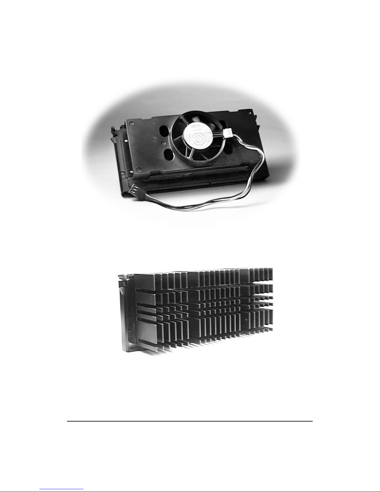
Pentium II Boxed (Active) CPU
Shown with Power Connector for Fan
Pentium II (Passive) CPU
Shown with Heatsink
7S1682D-001-02
Page 8

Chapter 2: Board Installation
2.1 Unpacking
2.1.1. Item Checklist
The motherboard package should contain the following:
• S1682D Motherboard • User's manual
• One IDE 40 pin cable • BIOS manual
• One 34 pin floppy cable • 2 Retention modules (M2100F)
2.1.2. Precautionary measures before handling the motherboard
Since the motherboard contains sensitive electronic components which can
easily be damaged by static electricity, the motherboard should be left in its
original packaging until it is ready to be installed.
Before you open the carton of your computer, do the following:
1. Make sure that you stand on an Anti-static mat. (Do not stand on a rug
or carpet.)
2. It is also strongly recommended that you wear an anti-static strap. (Antistatic straps can be purchased at your local computer hardware stores.)
3. With the power supply plugged in and the system turned off, touch an
unpainted area of the system chassis before handling the motherboard or
any component. Remember to repeat the above steps whenever you handle
the motherboard or its components.
2.1.3. Proper handling of the motherboard
After opening the S1682D motherboard carton, remove the board by holding its edges. Place it on a grounded anti-static surface with the component
side up. Inspect the board for damage. Do not touch the bottom of the
board.
(Note: DO NOT APPLY POWER TO THE BOARD IF IT HAS BEEN
DAMAGED!)
2.2 Installation of the motherboard
You are now ready to install your motherboard. The mounting hole pattern
of the S1682D matches the ATX system board specifications. Please install
the board in the chassis designed for a standard ATX form factor board.
8S1682D-001-02 http://www.tyan.com
Page 9

2.3.1 Motherboard Layout
J6
Com2
PS/2
Mouse
Power
PS/2
KB
1
J19
•••
CHSFAN
Parallel Port
J22
J21
USB1
USB2
Com1
•••••
•••••
•••
1
•••
1
J20
•••
CPUFAN
conn.
Pentium II Secondary Slot
PCI Slot 1
J30
J36
PCI Slot 2
PCI Slot 3
PCI Slot 4
PCI Slot 5
1
J23
•••
CPUFAN
82441FX
82442FX
Pentium II Primary Slot
1
••••••
J34
J37
••••
J33
J32
PIIX3
J11
J12
••••••
SIMM 0
SIMM 0
••
J24 J25
J31
••
••
Floppy
1
Primary
1
IDE
Secondary IDE
1
J13
J14
••
SIMM 1
SIMM 1
J26 J27
JP1
•••
J58
••
SIMM 2
SIMM 2
••
ALT IR
J16
J15
••
••
SIMM 3
SIMM 3
••
J29
••••
CON4
•••••••••••••••••••••••••••
Keyboard
(For more information about this mainboard, please visit our Web Page and
Clickable motherboards at http://www.tyan.com/html/faq.html.)
ISA Slot 1
J49
•••
J50
ISA Slot 2
ISA Slot 3
•••
J44
I/O
APIC
9S1682D-001-02
••
RTC
J60
CHSFAN
1
•••
Page 10

2.3.2 Summary of Jumper Settings
Refer to the following table for quick reference of jumper settings:
Jumper # Assignments Pg. #
J8, J10 Voltage ID: J10: Primary CPU, P.13
J8: Secondary CPU
J20, J23 CPU Fan P10, P21
J19 CHS Fan (Chassis Fan) P10
J11, J12, J37 Bus Speed P12
J13-J16, J24-27 DRAM Voltage Select P12
J21, J22 Universal Serial Bus (J21:USB2, J22:USB1) P14
J29 Pins 1,2:Power on,
Pins6-11:Infra Red, P14,15,16
Pins13-16:HDD LED, Pins18-20:Power LED
Pins22,23:Reset, Pins24-27: Speaker
J30, J36 I/O Select P12
J31-34 CPU Speed Settings P12
J39 Super I/O Clock Select P13
(*Do not Change) P13
J44 CMOS Reset P12,17
J56 BIOS EEPROM Voltage P14
(*Do not Change)
J1-J5,J9,J35, Reserved P14
J38,J45-55,J57
Block J29 Pin Assignments
Power on: Pins 1,2 (close)
(Cover Pins1&2 with a jumper cap to short the circuit
between these pins)
Infra Red: Pins 6-11 (close)
(Cover Pins6 to 11with a jumper cap and short the circuit
between these pins)
Reset: Pins 22, 23 (close)
HDD LED: Pins 13-16 (close)
(Cover Pins13 to 16 with a jumper cap and short the circuit
Power LED: Pins 18-20 (close)
between these pins)
10S1682D-001-02 http://www.tyan.com
(Cover Pins18 to 20 with a jumper cap and short the circuit
between these pins)
(Cover Pins22 & 23 with a jumper cap to short the circuit
between these pins)
Speaker:Pins24-27
(Cover Pins24 to 27 with a jumper cap and short the circuit
between these pins)
Page 11

2.3.3 Jumper Settings
CPU Speed Settings for Pentium II and Pentium Pro Processors:
MHz J31 J32 J33 J34 J37 J11 J12
150 open close close close 3-4 open open
166 open close close close 1-2 close open
180 close open close close 3-4 open open
200 close open close close 1-2 close open
233 open open close close 1-2 close open
266 close close open close 1-2 close open
300 open close open close 1-2 close open
CMOS Reset (Always reset after changing BIOS)
J44
Closed momentarily to reset
(Cover Pins 1 & 2 momentarily with a
jumper cap and short the circuit
J44
1 2
between these 2 pins)
Bus Speed
HOST PCI J11 J12 J37
60MHz 30MHz open close 3-4
66MHz 33MHz close open 1-2
J11 J12 J37 J11 J12 J37
60MHz 66MHz
1 2 3 4
DRAM Voltage Select
J15 J16 J26 J27 J13 J14 J24 J25
5V Close Close Close Close Open Open Open Open
3.3V Open Open Open Open Close Close Close Close
I/O Select COM2 Infra Red
J30 J36
1 2 3
J30 J36
J30 J36
1-2 2-3 1-2 2-3
COM2 Close Open Close Open
Infra Red Open Close Open Close
11S1682D-001-02
1 2 3 4
1 2 3
Page 12

Super I/O Clock Select (**Set at factory--Do not change!!)
1 2 3
J39
1-2 2-3
669IR Open Close
J39
BIOS EEPROM Voltage (Set at factory--DO NOT
change!!)
J56
1 2 3
J56
1-2 2-3 5V* 12V
5V (*default) Close Open
12V Open Close *Default
1 2 3
Wake on LAN connector: JP1
Pin# Signal
1 SB 5V
2 Ground
3 Wake up LAN
Reserved Jumpers:
J1-J5,J9, J35, J38, J42-43, J45-55, J57
12S1682D-001-02 http://www.tyan.com
Page 13

Connectors:
Block J29: (Refer to Page 10 for more information.)
Pin# Signal
1 & 2 Power On
6-11 Infra Red
13-16 HDD LED
18-20 Power LED
22 & 23 Reset
24-27 Speaker
J21/J22: Universal Serial Bus Ports
(J21: USB2, J22: USB1)
CON 5: FDD CON
CON 6: Primary IDE
CON 7: Secondary IDE
13S1682D-001-02
Page 14

Speaker Connector: J29 pins 24-27
Pin Signal
24 +5V
25 ground
27 Speaker data
(Refer to Page 10 for more information.)
HDD LED: J29 pins13-16
Pin Signal
13 +5V
15 HD Active#
16 HD_PWR
(Refer to Page 10 for more information.)
Infra Red Interface: J29 pins 6-11
Pin Signal
6 +5V
8 IR in
9 Ground
10 IR out
11 +5V
(Refer to Page 10 for more information.)
14S1682D-001-02 http://www.tyan.com
Page 15

2.4 CMOS RTC
The CMOS RTC includes an internal battery and real time clock circuit
which provides the date and the time, and the CMOS Chipset Default
Register for the system. Normally, the life span of a RTC internal battery is
more than 10 years. This RTC chip cannot be field upgraded and can only
be changed at a Tyan repairing facility.
2.5 Installing Cables and Connectors
2.5.1 Speaker Connector Installation (J29)
Your S1682D board provides a 4-Pin header to connect the speaker. The
speaker is connected to pins 24-27 of J29. (Refer to Page 9 and Page 10
for detailed information.)
2.5.2 Hardware Reset Switch Connector Installation (J29)
The RESET switch on your case's display panel provides you with the
HARDWARE RESET function which is the same as power on/off. The
system will do a cold start after the RESET switch is pushed by the user.
The RESET switch is a 2 pin connector and should be installed on pins
22 and 23 on J29. (Refer to Page 9 and Page 10 for detailed information.)
2.5.3 HDD LED Connector Installation (J29)
Your S1682D board provides a 4-Pin header to connect the HDDLED
cable. When connected, the HDDLED light on the panel of the case flashes
if a HDD activity is detected. The cable is connected to pins 13-16 of J29.
(Refer to Page 9 and Page 10 for detailed information.)
2.5.4 Power LED Connector Installation (J29)
The S1682D board also provides a 3-Pin header to connect the Power LED
cable. When connected, the Power LED light on the panel of the case
indicates power on/off of the system. The cable is connected to pins 18-20
of J29. (Refer to Page 9 and Page 10 for detailed information.)
2.5.5 Infra Red Connector Installation (J29)
The S1682D board provides a 6-Pin connector (Pins 6-11 of J29) for the
Infra Red cable which connects to a Homing Device on the back of the
case. When activated, the Homing Device will send out IR signals to remote I/O IR devices. (Refer to Page 9 and Page 10 for detailed information.)
15S1682D-001-02
Page 16

2.5.6 Flash ROM-Jumper J56
The S1682D uses flash memory to store BIOS Setups. It can be updated
as new versions of the BIOS become available. The flash utility will guide
you through the process step by step. However, we do not recommend
that you flash the onboard BIOS. This procedure should only be
done by a qualified technician or a Tyan technical support engineer.
J56 determines which type of Flash EPROM is used. This jumper has been
set to match the onboard BIOS chip. The factory default for the S1682D
is on pins 1-2(5V). Depending on the type of EPROM used, some boards
will have J56 on pins 2-3(12V). (Refer to Page 13 for more information.)
*****************************************************
Warning!!
*Do not change J56--(It has been pre-configured at the factory.)
2.5.7 Hardware CMOS & Password Reset
If you are locked out of your system because you have forgotten your
password, or you have set the CMOS incorrectly, follow the instructions
below.
a. Power off the system.
b. Short J44 by covering Pin 1 and Pin 2 of J44 with a jumper cap
and short the circuit between these two pins.
c. Wait for 5 seconds, and, then, remove the jumper cap from J44.
d. Apply power to the system.
By following the above procedures, the password and CMOS will be reset
to BIOS defaults.
16S1682D-001-02 http://www.tyan.com
Page 17

2.6 DRAM Installation
The S1682D uses a 64-bit data path from memory to the CPU which will
accommodate up to 512MB of RAM. The motherboard supports FPM
(Fast Page Mode), EDO (Extended Data Out), ECC (Error Correcting
Code), and Parity 72-pin SIMMs.
The following table shows some of the available memory configurations.
Bank 0 Bank 1 Bank 2 Bank 3 Total
4MBx2 none none none 8MB
8MBx2 none none none 16MB
4MBx2 4MBx2 none none 16MB
8MBx2 8MBx2 none none 32MB
4MBx2 4MBx2 4MBx2 4MBx2 32MB
16MBx2 none none none 32MB
16MBx2 16MBx2 none none 64MB
32MBx2 none none none 64MB
64MBx2 none none none 128MB
16MBx2 16MBx2 16MBx2 16MBx2 128MB
32MBx2 32MBx2 none none 128MB
32MBx2 32MBx2 32MBx2 none 192MB
32MBx2 32MBx2 32MBx2 32MBx2 256MB
64MBx2 64MBx2 none none 256MB
128MBx2 none none none 256MB
64MBx2 64MBx2 64MBx2 none 384MB
64MBx2 64MBx2 64MBx2 64MBx2 512MB
128MBx2 128MBx2 none none 512MB
17S1682D-001-02
Page 18

2.7 Level 2 Cache Memory/SRAM Memory
The S1682D's L2 Cache Memory is built into the Intel Pentium II CPU.
There are no L2 Cache Memory slots or SRAM slots on the
motherboard.
2.8 VRM (Voltage Regulator Module)
The CPU will program the VRM for the correct voltage needed. No
jumper settings are required. The S1682D has two built-in VRM's on
board.
2.9 Peripheral Device Installation
Install the motherboard after you have checked all of the jumper settings.
Also be sure to check all connectors thoroughly and read the technical
manuals that come with your peripheral cards before you install your addon peripheral cards.
If a PCI-Bus interface card is to be installed in the system, any one of the
five PCI-Bus slots will support either a Master or a Slave device.
2.10 Connecting the Power Supply and On/Off Switch
The system is configured for a standard ATX power supply. The ATX
connectors can only be plugged in one way and should install easily.
18S1682D-001-02 http://www.tyan.com
Page 19

Chapter 3: CPU Installation and Removal
Pentium II (233 through 300MHz) and Pentium Pro Processors (150 through
200 MHz) can be used on the S1682D. Please refer to section 2.3 for the
correct CPU jumper settings for your board. Although the S1682D
motherboard is designed as a dual CPU system, it will also function with a
single CPU.
The S1682D board provides two slots for Pentium II Processors--(Pentium
II Primary and Secondary Slots). If only one CPU is used, the CPU should be
plugged into the Primary Slot. However, when two CPUs are used, these CPUs
should be of the same speed and type.
Caution!! The CPU is a sensitive electronic component which can be easily
damaged by static electricity. Do not touch the CPU pins with your fingers.
3.1 Installation of Pentium II Boxed (Active) Processors
(Note: Active Processors are equipped with cooling fans. When installing an
Active CPU, you also need to connect the cooling fan cable to its connector.)
Installing CPU Retention Modules
1. Installation of a Pentium II Active Processor requires a CPU Retention
Module, which is first secured onto the motherboard. (Refer to the
motherboard layout on Page 10.)
2. To attach the Retention Module, place the motherboard on a flat
surface.
3. Locate the key pin on one end of the Pentium II Slot on the board.
Then carefully line up the key
notch on the Retention Module
with the key pin on the Pentium
II Slot. (The key pin on the
Pentium II Slot indicates the
correct orientation of the CPU.)
Pentium II Slot Connector
and Key Pin
19S1682D-001-02
Page 20

4. Drop the Retention Module down over the
Pentium II Slot so that the Retention Module
seats flat against the motherboard. Tighten the
screws in a clockwise manner to secure the
module to the board. (Warning — Do not
overtighten the screws as you may damage
the module and/or the motherboard.)
Retention Module
Installing CPUs
5. When the Retention Module is securely installed, you are ready to plug the
CPU into the Retention Module. Make sure that the CPU's Cooling Fan is
turned away from the I/O connectors before you plug the CPU into the CPU
module.
6. Press firmly on the CPU until you hear a "click". The Pentium II CPU will
make a clicking sound when it is fully locked into the Retention Module.
7. After the CPU is securely seated on the Retention Module in the Pentium
II Slot , connect the CPU's Cooling Fan cable to the Cooling Fan power
Connector on the board.
3.2 Installing CPU Cooling Fans
8. Locate the Cooling Fan Connectors (2 Connectors: J20 and J23--1 for each
CPU) on the motherboard.
9. Plug the CPU's Cooling Fan Cable into the Cooling Fan Connector on
the board. Make sure that the black wire of the cable is plugged into Pin 1
of the connector. (Refer to Pin 1 marked on the layout on P10.) (Pin
Assignments: Pin 1: ground--black, Pin 2: 12 V--red, Pin 3: Signal--yellow.)
20S1682D-001-02 http://www.tyan.com
Page 21

3.4 Installation and Removal of Pentium II Passive Processors
(Unlike Active Processors, Passive Processors are not equipped with
cooling fans. Passive
Processors are equipped
with heat sinks instead.)
Each CPU package should
also contain the following:
CPU Retention Module (x1)
Heat-sink Retention Bracket
with mounting locks (x1)
Mounting Attach-mounts (x 2)
Heat-sink Lock (x1)
Pentium II Passive CPU Module
3.4.1 Installing CPU
Retention Modules
1. When installing the CPU
Retention Module, make sure
that you have the appropriate
end of the module lined up with
the key notch on the Pentium II
Slot connector. This will
ensure that the module is installed properly.
Retention Module
2. Before tightening the screws, make certain that the module is flush
against the motherboard. If one end of the module is raised above the
board, check the orientation of the module.
3. Install the module on the board by turning the screws in a clockwise
direction. (Do not over tighten the screws).
21S1682D-001-02
Page 22

3.4.2 Installing Heat-sink Mounting Brackets
1. The heat-sink mount has two pins on the bottom and 4 pins on the top.
Notice that the bottom two pins are of different sizes. The size of the
pins and the holes in the motherboard will determine the correct orienta-
tion. A correctly
installed bracket can
be verified by noting
the 4 pins on the top.
These 4 pins should be
closest to the Pentium
II CPU slot.
Heat-sink Mounting Bracket
2. Insert the heat-sink mount into the holes
on the motherboard. When the bracket is
properly inserted into the holes on the
motherboard, you will hear a clicking noise .
3. Lock the heat-sink mount to the board by
inserting the two mounting locks into the pins
of the heat-sink mounting bracket which are
now below the mainboard. There will be a
click when the locks are securely
fastened.
Mounting Locks
3.4.3 Installing Pentium II Passive Processors
1. Align the CPU with the CPU retention module. Make sure the heatsink is lined up with the heat-sink mount bracket. If you put the CPU in
the wrong way, you may damage the CPU, the motherboard, and/or the
CPU socket.
2. Slowly press down on the CPU module until the CPU locks into place.
A clicking noise will be heard when the CPU is locked securely into the
module.
22S1682D-001-02 http://www.tyan.com
Page 23

3.4.4 Installing Heat-sink Locks
The heat-sink lock has 4 notches which will correspond to the 4 pins on
the heat-sink mounting bracket. Gently slide the lock between the heatsink onto the heat-sink mounting bracket until both sides of the lock are
firmly secured. A clicking sound will be heard when the lock is securely
fastened to the heat-sink mounting bracket. To remove the lock from the
heat-sink mounting bracket, gently
press the ends of the locks inward
and pull.
Heat-Sink Lock
3.4.5 Removing Pentium II Passive Processors and CPU
Retention Modules
To remove the CPU, move the locks to the center of the CPU. A click
will be heard when the CPU has been unlocked. Gently pull up on
the CPU, taking care not to bend the motherboard or the CPU Retention Module.
3.4.6: Removing Heat-Sink Locks
To remove the lock from the Retention Bracket, gently press the ends
of the locks inward and pull.
23S1682D-001-02
Page 24

Chapter 4: Troubleshooting
4.1 Troubleshooting Procedures
Use the following procedures to troubleshoot your system. If you have followed
all of the procedures below and still need assistance, refer to the "Technical
Support Procedures" and/or "Returning Merchandise for Service" section(s) in
this chapter.
No-Video
If you do not have video, follow the Troubleshooting Flowchart on the next
page.
1. Check for missing jumpers or improper installation of the ROM BIOS.
2. Make sure the video card and its jumper setting (as appropriate) match the
monitor type.
3. Check to make sure that all peripheral cards are properly installed in their
slots.
4. The I/O Bus speed should be running at the standard speed of 8 MHz.
5. Use the speaker to determine if any beep codes exist. Refer to Addendum A
and Addendum B for details about beep codes.
Note: If you are a system integrator, VAR, or OEM, a POST diagnostics card is
recommended for Port 80h codes. (Please visit our Web Site for detailed
information.)
Memory Error/Parity Error
If you encounter memory or parity errors, follow the procedures below.
1. Check to determine if SIMM modules are improperly installed.
2. Make sure that different types of SIMMs have not been installed in the
same bank. (eg. a mixture of 265KB x 9 and 1 MB x 9)
24S1682D-001-02 http://www.tyan.com
Page 25

3. Determine if different speeds of SIMMs have been installed in the
same or different banks, and the BIOS setup is configured for the
slowest speed of RAM used. It is recommended to use the same
RAM speed for SIMMs in different banks.
4. Check for bad SIMM modules and chips.
Troubleshooting Flowchart
25S1682D-001-02
Page 26

Losing the System's Setup Configuration
1. Make sure that you are using a high quality power supply. A poor quality
power supply may cause the system to lose its CMOS setup.
2. Determine if the Dallas Battery is bad. If it is bad, replace it with a good one.
The following steps will help you determine if the RTC is bad:
a. Turn on the system and set the system clock.
b. Let the system run for more than 6 hours.
c. Check the system clock to see if it has accurate timing.
If the system timing is off, it is likely that the RTC battery is bad.)
3. If the above steps do not fix the Setup Configuration problem, contact your
vendor for repair.
4.2 Technical Support Procedures
Be sure to go through the "Troubleshooting Procedures" section in this Chapter,
and visit our Web site for additional information before calling Technical
Support. (Tyan's Web Site address is: http://www.tyan.com.)
If the problem is still not resolved, have the following information ready before
you call for technical support:
1. System Board Serial Number
2. CPU Serial Number
3. Invoice Number, Date
4. Purchase Form
5. Sale's Person's name
6. Product Configurations
4.3 Returning Merchandise for Service
For technical support be sure to contact your Dealer or Distributor FIRST in the event your product is not working properly.
A receipt or a copy of your invoice marked with the date of purchase is required
before any warranty service will be rendered. You can obtain service by calling
the manufacturer for a Return Merchandise Authorization (RMA) number. The
RMA number should be prominently displayed on the outside of the shipping
carton and mailed prepaid, or hand-carried to the manufacturer. Shipping and
handling charges will be applied for all orders that must be mailed when service is
complete. During the warranty period, contact your distributor first for any
product problems.
This warranty only covers normal consumer use and does not cover damages
incurred in shipping or from failure due to the alteration, misuse, abuse, or
improper maintenance of products.
26S1682D-001-02 http://www.tyan.com
Page 27

Appendix: LM78 System Hardware Monitor and LANDesk Client
Manager (LDCM)
To enhance the performance of your computer system, Tyan has incorporated National Semiconductor's LM78 Microprocessor System Hardware Monitor and LANDesk Client Manager (LDCM) into the S1682 D
board design. The LM78 is an Integrated Data Acquisition system,
designed to monitor power supply voltages, temperatures, and fan speeds.
To achieve this purpose, the LM78, a hardware monitor component, has
an on-chip temperature sensor, 5 positive analog inputs, two inverting
inputs and an 8-bit ADC. In addition, the LM78 also provides ISA and
Serial Bus Interfaces. A 32-byte auto-increment RAM is provided for
POST (Power On Self Test) code storage.
Features
The LM78 includes the following features:
* Temperature sensoring
* 5 positive voltage inputs
* 2 op amps for negative voltage monitoring
* 3 fan speed monitoring inputs
* Input for additional temperature sensors
* Chassis Intrusion Detector Input
The software program-- LDCM (LANDesk Client Manager) is used as
the LM78's drivers to accomplish monitoring computers' temperatures
and voltages. The LDCM Drivers use the LM78 to monitor critical
hardware components and enable remote sensing and diagnostics of your
S1682D Board. Thus, by implementing both National Semiconductor's
LM78 and LDCM in the S1682D system, Tyan provides you with the
best quality board possible on the market.
For more information, please refer to the Web Page at:
http://www.tyan.com
27S1682D-001-02
Page 28

Compliance Information Statement
( Declaration of Conformity Procedure-DOC)
Notice for the USA
FCC Part 15: This Device complies with Part 15 of the FCC Rules.
Operation is subject to the following conditions:
1) this device may not cause harmful interference, and
2) this device must accept any interference received
including interference that may cause undesired operation.
If this equipment does cause harmful interference to radio or television
reception, which can be determined by turning the equipment off and on,
the user is encouraged to try one or more of the following measures:
w Reorient or relocate the receiving antenna.
w Increase the separation between the equipment and receiver.
w Connect the equipment into an outlet on a circuit different from that of the
receiver connected.
w Consult the dealer or an experienced radio/TV technician for help.
Notice for Canada
This apparatus complies with the Class "B" limits for radio interference as
specified in the Canadian Department of Communications Radio Interfer
ence Regulations.
Cet appareil est conforme aux normes de CLASSE "B" d' interference radio
tel que spec' cifie' par le Ministe're Canadien des Communications dans les
re'glements d'interfe'rence radio.
Notice for Europe (CE Mark)
This product is in conformity to the Council Directive 89/336/EEC, 92/31/
EEC(EMC)
Information presented in this publication has been carefully checked for
reliability; however, no responsibility is assumed for inaccuracies. The
information contained in this document is subject to change without
notice.
Award BIOS/Flash are trademarks of Award Software International Inc.
AMI BIOS is a trademarks of American Megatrends Inc.
IBM,PC,AT,PS/2 are trademarks of IBM Corporation
INTEL,Pentium are trademarks of Intel Corporation.
Acknowledgment
Trademarks
28S1682D-001-02 http://www.tyan.com
Page 29

Chapter 6: Speaker Beep codes
All Tyan motherboards come with a BIOS feature called "beep codes".
What these do is inform you (the user) about potential problems in your configuration.
These errors can occur during POST (Power On Self Test), which is
performed every time the system is powered on. Fatal errors are communicated
through a series of audible beeps from your computers' speaker. Should an error
of this sort occur, listen carefully to these beeps and match the description from
the table below to determine the source of the problem.
Beeps Error message Description
1 Refresh Failure The memory refresh circuitry
on the motherboard is faulty.
2 Parity Error Parity error in the first 64KB
of memory.
3 Base 64KB Memory Failure Memory failure in first 64KB
of memory.
4 Timer Not Operational Memory failure in
the first 64KB of memory,
or Timer 1 on the
motherboard is not functioning.
5 Processor Error The CPU on the motherboard
generated an error.
6 8042 - Gate A20 Failure The keyboard controller may
be bad.
7 Processor Exemption Interrupt Error The CPU generated an
exeption interrupt.
8 Display Memory Read/Write Error The system video adapter is
either missing or its memory is
faulty.
9 ROM Checksum error The ROM checksum
value does not match the
value encoded in the
BIOS.
10 CMOS Shutdown Register R/W Error The shutdown register for
CMOS RAM failed.
11 Cache Error / External Cache Bad The external cache
is faulty.
29S1682D-001-02
 Loading...