

Tyan S8812 User Manual

S8812
Version 1.1
Copyright
Copyright © 2010 MiTAC International Corporation. All rights reserved. No part of
this manual may be reproduced or translated without prior written consent from
MiTAC International Corporation.
Trademark
All registered and unregistered trademarks and company names contained in this
manual are property of their respective owners including, but not limited to the
following.
TYAN® is a trademark of MiTAC International Corporation.
®
AMD
is a trademark of AMD® Corporation.
®
is a trademark of Intel® Corporation.
Intel
AMI, AMI BIOS are trademarks of AMI Technologies.
Microsoft®, Windows® are trademarks of Microsoft Corporation.
Winbond
®
is a trademark of Winbond Electronics Corporation.
Notice
Information contained in this document is furnished by MiTAC International
Corporation and has been reviewed for accuracy and reliability prior to printing.
MiTAC assumes no liability whatsoever, and disclaims any express or implied
warranty, relating to sale and/or use of TYAN
warranties relating to fitness for a particular purpose or merchantability. MiTAC
retains the right to make changes to product descriptions and/or specifications at
any time, without notice. In no event will MiTAC be held liable for any direct or
indirect, incidental or consequential damage, loss of use, loss of data or other
malady resulting from errors or inaccuracies of information contained in this
document.
®
products including liability or

http://www.tyan.com
2

Contents
Before you begin….................................................................................... 4
Chapter 1: Instruction ................................................................................5
1.1 Congratulations .................................................................................5
1.2 Hardware Specifications.................................................................... 5
1.3 Software Specifications ..................................................................... 6
Chapter 2: Board Installation..................................................................... 7
2.1 Board Image ...................................................................................... 8
2.2 Block Diagram ................................................................................... 9
2.3 Board Parts, Jumpers and Connectors ........................................... 10
2.4 Installing the Processor and Heat sink............................................ 22
2.5 Thermal Interface Material ..............................................................25
2.6 Tips on Installing Motherboard in Chassis ......................................26
2.7 Installing the Memory ......................................................................28
2.8 Attaching Drive Cables .................................................................... 35
2.9 Installing Add-In Cards .................................................................... 36
2.10 Connecting External Devices ........................................................37
2.11 Installing the Power Supply ........................................................... 38
2.12 Finishing Up................................................................................... 39
Chapter 3: BIOS Setup ............................................................................. 41
3.1 About the BIOS................................................................................ 41
3.2 Main Menu....................................................................................... 43
3.3 Advanced Menu............................................................................... 44
3.4 PCI/PnP Menu................................................................................. 72
3.5 Boot Menu ....................................................................................... 74
3.6 Security Menu.................................................................................. 76
3.7 Chipset Menu ..................................................................................78
3.8 Exit Menu......................................................................................... 87
Chapter 4: Diagnostics............................................................................. 89
4.1 Beep Codes..................................................................................... 89
4.2 Flash Utility ...................................................................................... 89
4.3 AMIBIOS Post Code........................................................................ 90
Glossary..................................................................................................... 93
Technical Support ....................................................................................99
http://www.tyan.com
3
Before you begin…
Check the box contents!
The retail motherboard package should contain the following:
1x S8812 Motherboard
1 x Serial ATA Cable
1 x S8812 User’s manual
1 x S8812 Quick reference guide
1 x TYAN® Driver CD
1 x I/O shield
2 x mini SAS to mini SAS Cable
http://www.tyan.com
4

Chapter 1: Instruction
1.1 Congratulations
You have purchased the powerful TYAN® S8812 motherboard, based on the
®
SR5690 & SP5100 chipsets. The S8812 is designed to support quad
AMD
®
AMD
45nm 8-Core/12-Core Opteron 6100 Series Processors and up to 256GB
of 800, 1066 and 1333MHz UNB or REG/ECC DDR3 memory, as well as lowvoltage DDR3 memory modules. Leveraging advanced technology from AMD®,
the S8812 is capable of offering scalable 32 and 64-bit computing, highbandwidth memory design, and lightning-fast PCI-E bus implementation.
The S8812 not only empowers you in today’s demanding IT environment but also
offers a smooth path for future application upgradeability. All of these rich feature
sets provides the S8812 with the power and flexibility to meet demanding
requirements for today’s IT environments.
Remember to visit the TYAN® website at http://www.tyan.com. There you can
find all the information on all TYAN® products as well as all the supporting
documentation, FAQs, Drivers and BIOS upgrades.
1.2 Hardware Specifications
S8812WGM3NR
Processor
Chipset
Memory
Expansion Slots PCI-E
Recommended
Barebone / Chassis
LAN
Storage
Supported CPU
Series
Socket Type / Q'ty G34 / (4)
Average CPU Power
(ACP) wattage
System Bus Up to 6.4 GT/s Hyper-Transport link support
Chipset AMD SR5690 + SP5100
Super I/O Winbond W83627DHG
Supported DIMM Qty (32) DIMM slots
DIMM Type / Speed U/RDDR3 & LV RDDR3, 800/1066/1333 MHz
Capacity Up to 256GB
Memory channel 4 Channels per CPU
Memory voltage 1.5V or 1.35V
4U Barebone FT48-B8812
Port Q'ty (3)
Controller Intel 82574L / Intel 82576EB
Connector (2) Mini-SAS connectors (totally support 8 ports)
Controller LSI SAS2008
SAS
Speed 6.0 Gb/s
RAID RAID 0/1/1E/10 (LSI Integrated RAID)
Connector (1) SATA
SATA
Controller AMD SP5100
Speed 3.0 Gb/s
AMD 45nm 8-Core/12-Core Opteron 6100 Series Processors (MagnyCours) / (4) HT3; 12MB L3 per socket
Up to 105W
(1) PCI-E Gen.2 x8 slot / (1) PCI-E Gen.2 x16 slot (w/ x16 or x8 link) /
(1) PCI-E Gen.2 x8 slot (w/ x0 or x8 link) / (1) PCI-E Gen.2 x8 slot
(open-end)
5
http://www.tyan.com

Graphic
Input /Output
System Monitoring
Server Management
BIOS
Physical Dimension
Operating System OS supported list Please visit our Web site for the latest OS supported list.
Regulation
Operating
Environment
RoHS RoHS 6/6 Complaint Yes
Package Contains
Connector type D-Sub 15-pin
Resolution 1600x1200@60Hz
Chipset Aspeed AST2050
USB (7) USB2.0 ports (2 at rear, 4 via cable, 1 type A onboard)
COM (2) ports (1 at rear, 1 via cable)
PS/2 (1) PS/2 connector
SAS (2) Mini-SAS (4-in-1) connectors
VGA (1) D-Sub 15-pin VGA port
RJ-45 (2) GbE ports / (1) RJ-45 port for IPMI
Power
Front Panel (1) 2x12-pin SSI front panel header
Chipset Winbond W83795G
Voltage Monitors voltage for CPU, memory, chipset & power supply
Fan Total (9) 4-pin headers
Temperature Monitors temperature for CPU & system environment
LED
Others Chassis intrusion detection / Watchdog timer support
Onboard Chipset Onboard Aspeed AST2050
AST2050 IPMI
Feature
AST2050 iKVM
Feature
Brand / ROM size AMI / 4MB
Feature
Form Factor MEB
Board Dimension 16.2"x13" (411x330mm)
FCC (DoC) Class B
CE (DoC) Yes
Operating Temp. 10° C ~ 35° C (50° F~ 95° F)
Non-operating Temp. - 40° C ~ 70° C (-40° F ~ 158° F)
In/Non-operating
Humidity
Motherboard (1) S8812 Motherboard
Manual (1) User's manual / (1) Quick Ref. Guide
Installation CD (1) TYAN installation CD
I/O Shield (1) I/O Shield
SATA (1) SATA signal cable
Cable
SAS (2) Mini-SAS to Mini-SAS cable
ATX12V / 4-pin auxiliary power connector / Universal 24-pin + 8-pin +
8-pin power connectors
Fan fail LED indicator / Over temperature warning indicator / Fan & PSU
fail LED indicator
IPMI 2.0 compliant baseboard management controller (BMC) / Supports
storage over IP and remote platform-flash / BIOS update
24-bit high quality video compression / Dual 10/100 Mb/s MAC
interfaces
Plug and Play (PnP) /PCI2.3 /WfM2.0 /SMBIOS2.3 /PXE boot / ACPI 2.0
power management /Power on mode after power recovery / Userconfigurable H/W monitoring / Auto-configurable of hard disk types
90%, non-condensing at 35° C
1.3 Software Specifications
For OS (operation system) support, please check with TYAN® support for latest
information.
Remember to visit our Web site at http://www.tyan.com
User’s Guide.
for the latest AST2050
http://www.tyan.com
6

Chapter 2: Board Installation
You are now ready to install your motherboard.
How to install our products right… the first time
The first thing you should do is reading this user’s manual. It contains important
information that will make configuration and setup much easier. Here are some
precautions you should take when installing your motherboard:
(1) Ground yourself properly before removing your motherboard from the
antistatic bag. Unplug the power from your computer power supply and
then touch a safely grounded object to release static charge (i.e. power
supply case). For the safest conditions, MiTAC recommends wearing a
static safety wrist strap.
(2) Hold the motherboard by its edges and do not touch the bottom of the
board, or flex the board in any way.
(3) Avoid touching the motherboard components, IC chips, connectors,
memory modules, and leads.
(4) Place the motherboard on a grounded antistatic surface or on the antistatic
bag that the board was shipped in.
(5) Inspect the board for damage.
The following pages include details on how to install your motherboard into your
chassis, as well as installing the processor, memory, disk drives and cables.
NOTE: Do not apply power to the board if it has been damaged.
http://www.tyan.com
7
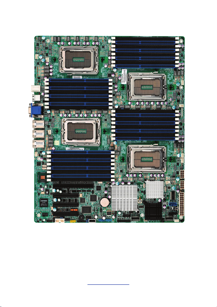
2.1 Board Image
This picture is representative of the latest board revision available at the time of
publishing. The board you receive may not look exactly like the above picture.
http://www.tyan.com
8
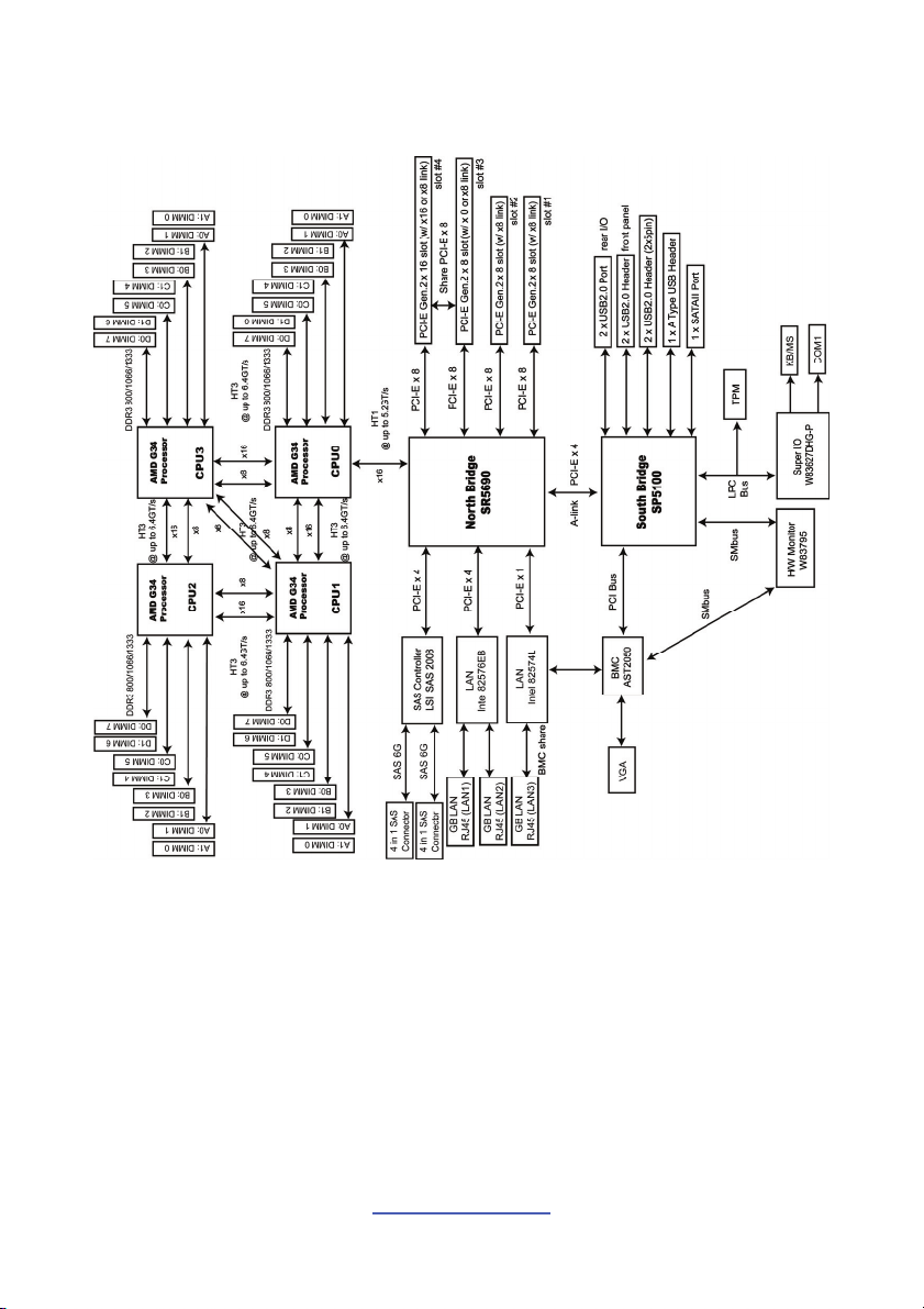
2.2 Block Diagram
S8812 Block Diagram
http://www.tyan.com
9
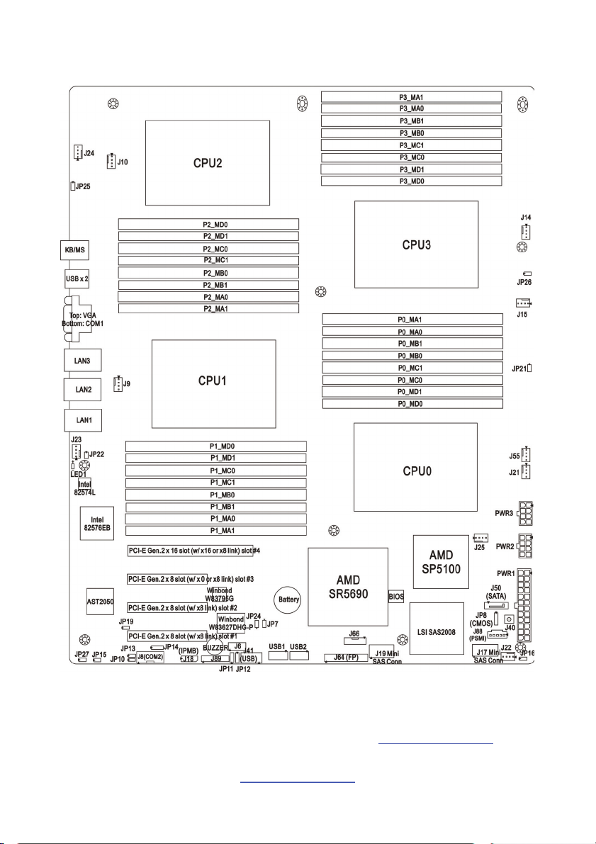
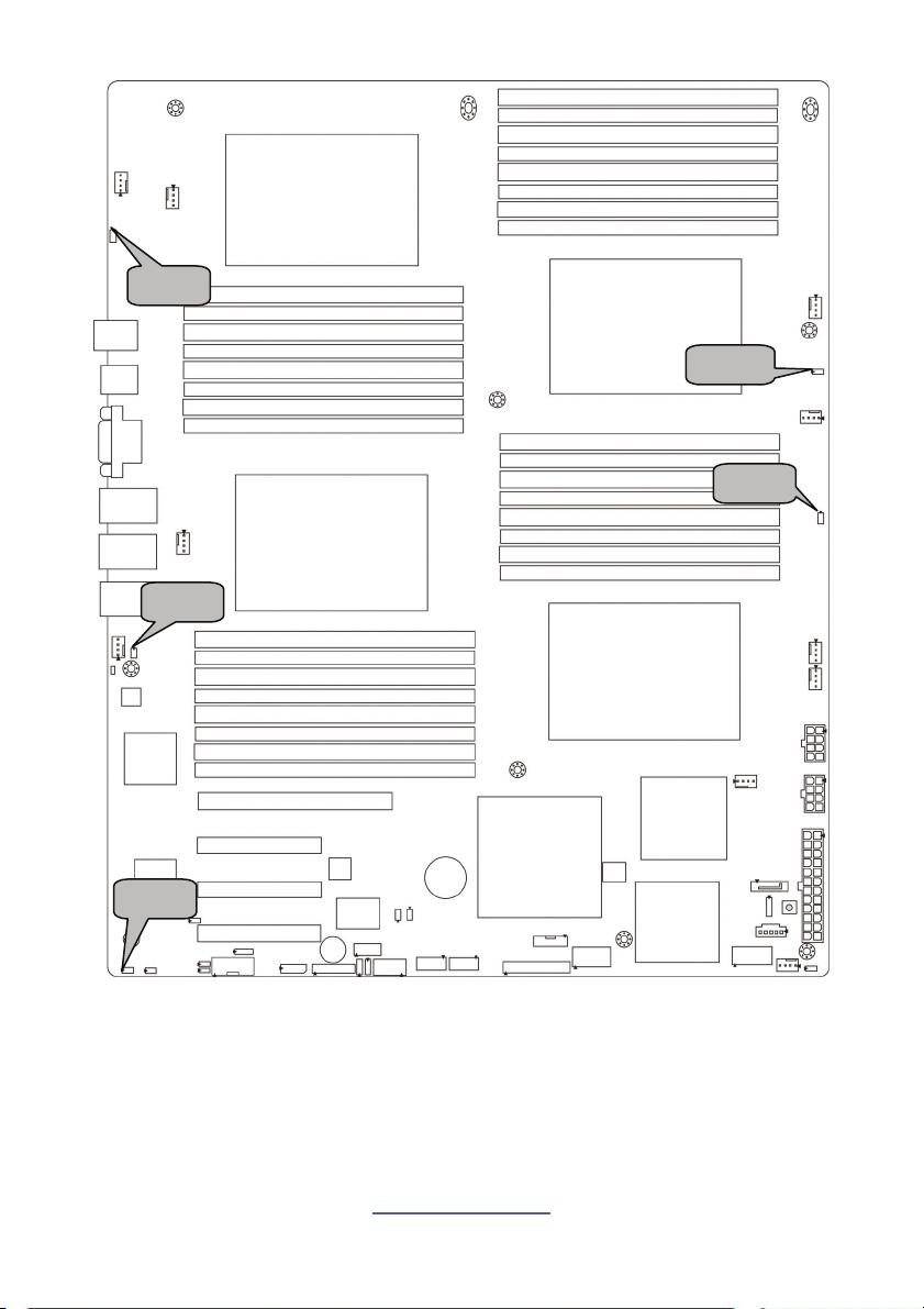
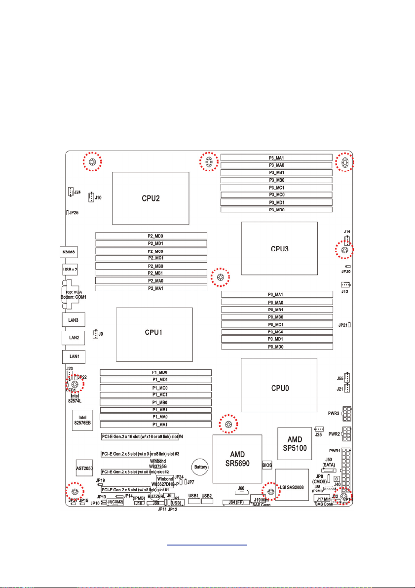
2.3 Board Parts, Jumpers and Connectors
This diagram is representative of the latest board revision available at the time of
publishing. The board you receive may not look exactly like the above diagram. But
for the DIMM number please refer to the above placement for memory installation.
For the latest board revision, please visit our web site at http://www.tyan.com
http://www.tyan.com
10
.
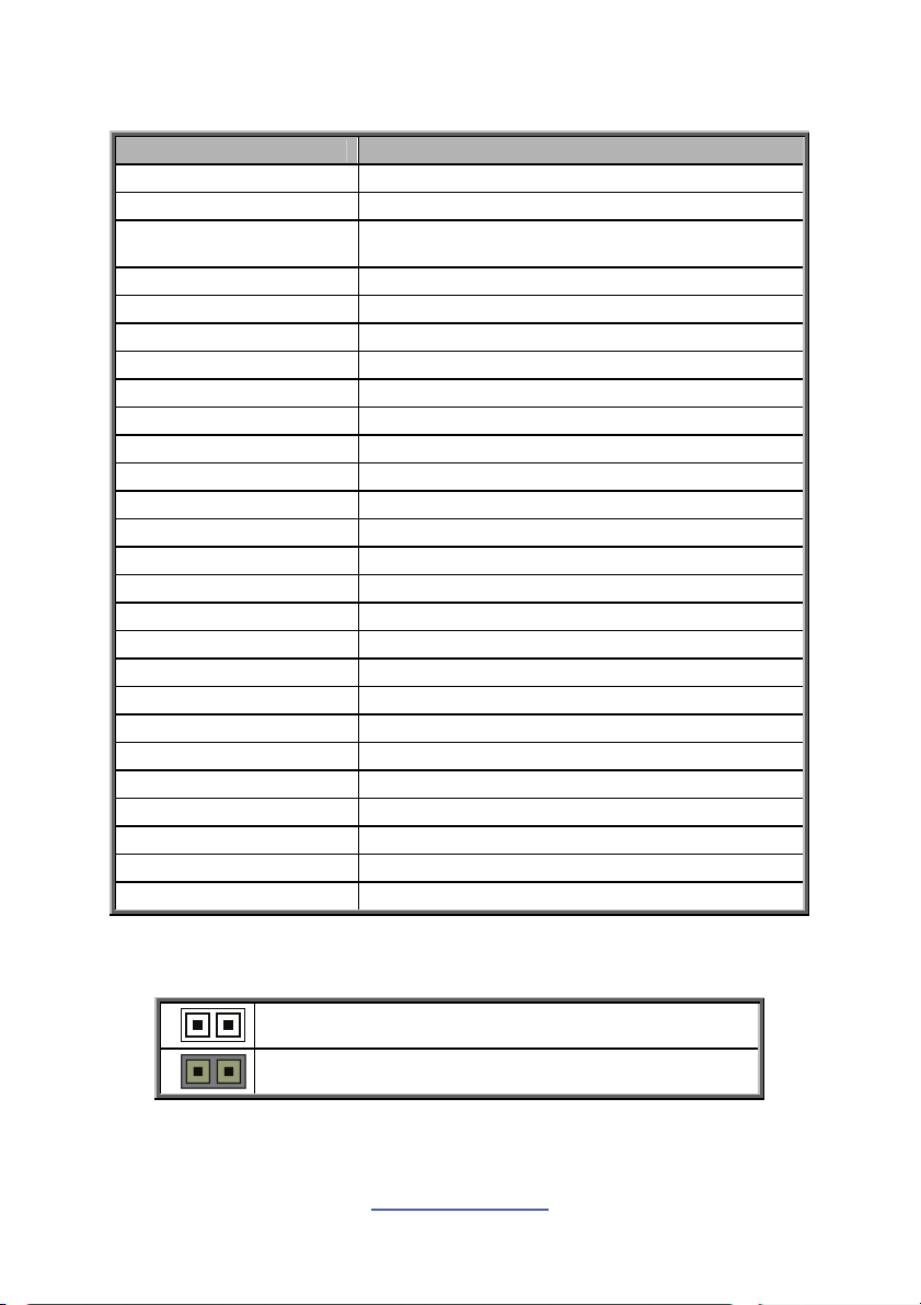
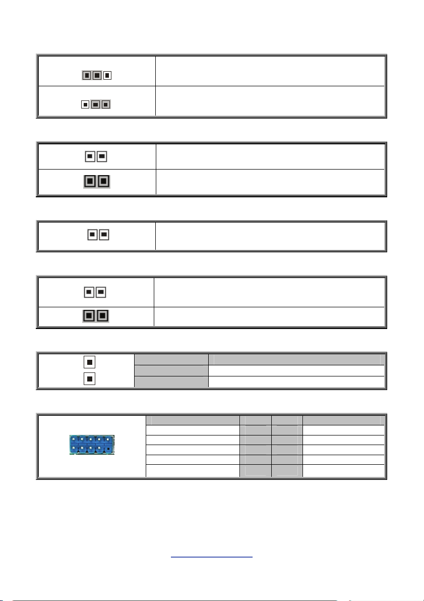
Jumpers & Connectors
Jumper/Connector Function
J6 CPLD JTAG Connector
J8 (COM2) COM2 Header
J9/J10/J14/J15/J21/
J22/J23/J24/J25/J55
J17/J19 Mini SAS Connector
J18 (IPMB) IPMB Connector
J40 Power Switch
J41 (USB) Vertical (Type A) USB Connector
J50 (SATA) Serial ATA Connector
J64 (FP) Front Panel Connector
J66 SAS Fault LED Connector
J88 (PSMI) PSMI Connector
J89 Fan TACH Connector
JP7 PCI-E x8/x16 Select Jumper
JP8 Clear CMOS Jumper
JP10 BMC Disable Jumper
JP11/JP12 COM2 Switch Jumper
JP13 TPM Disable Jumper
JP14 COM Power Select Jumper
JP15 WDT Trigger NMI Jumper
JP16 Chassis Intrusion Header
JP19 VGA Disable Jumper
JP21/JP22/JP25/JP26 DDR3 VDDIO Voltage Select Jumper
JP24 LAN3 LED Connector
JP27 ID LED Connector
LED1 ID LED
USB1/USB2 USB Front Panel Header
Jumper Legend
4-pin Fan Connectors
OPEN - Jumper OFF
CLOSED - Jumper ON
http://www.tyan.com
11
Without jumper cover
With jumper cover
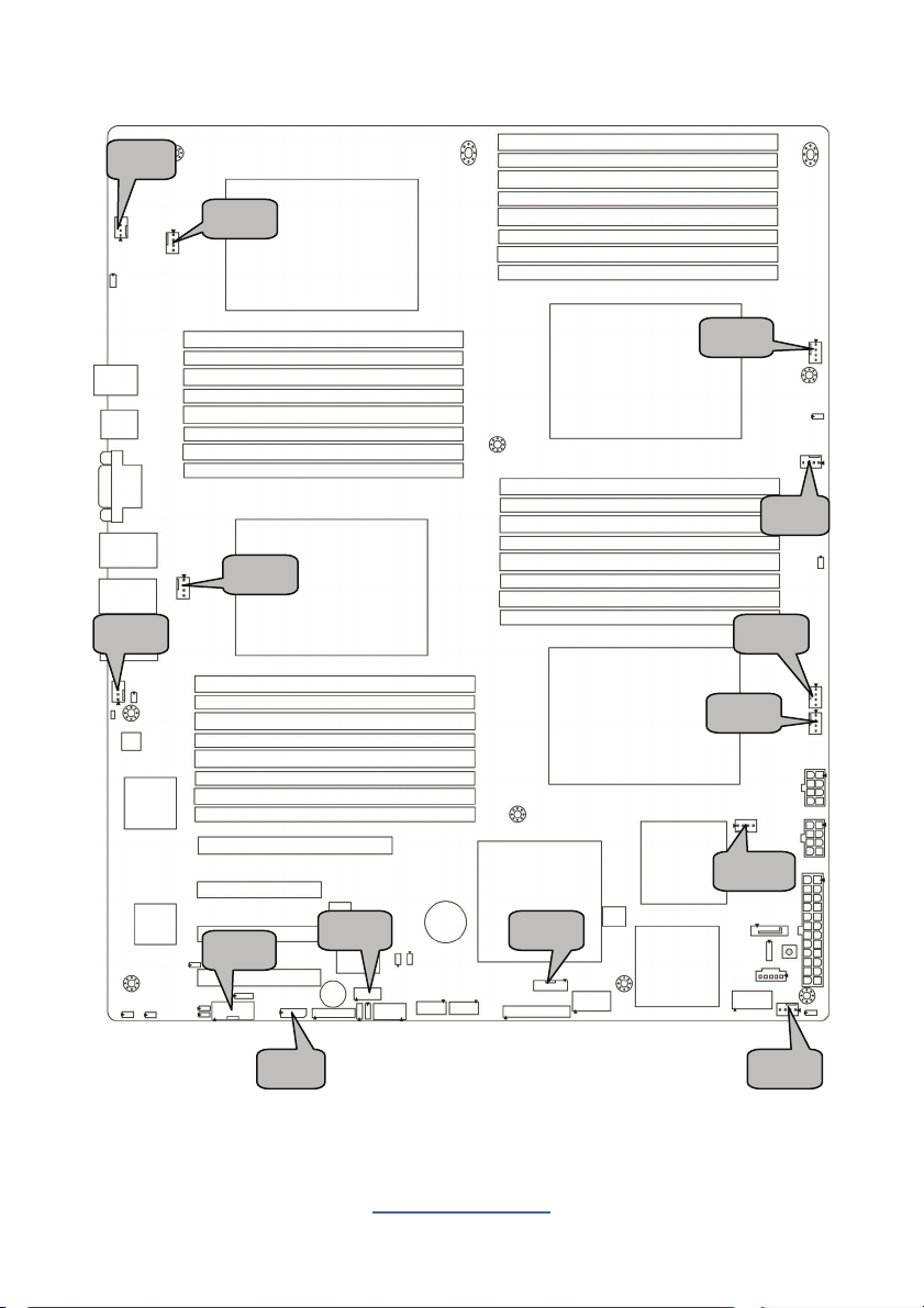
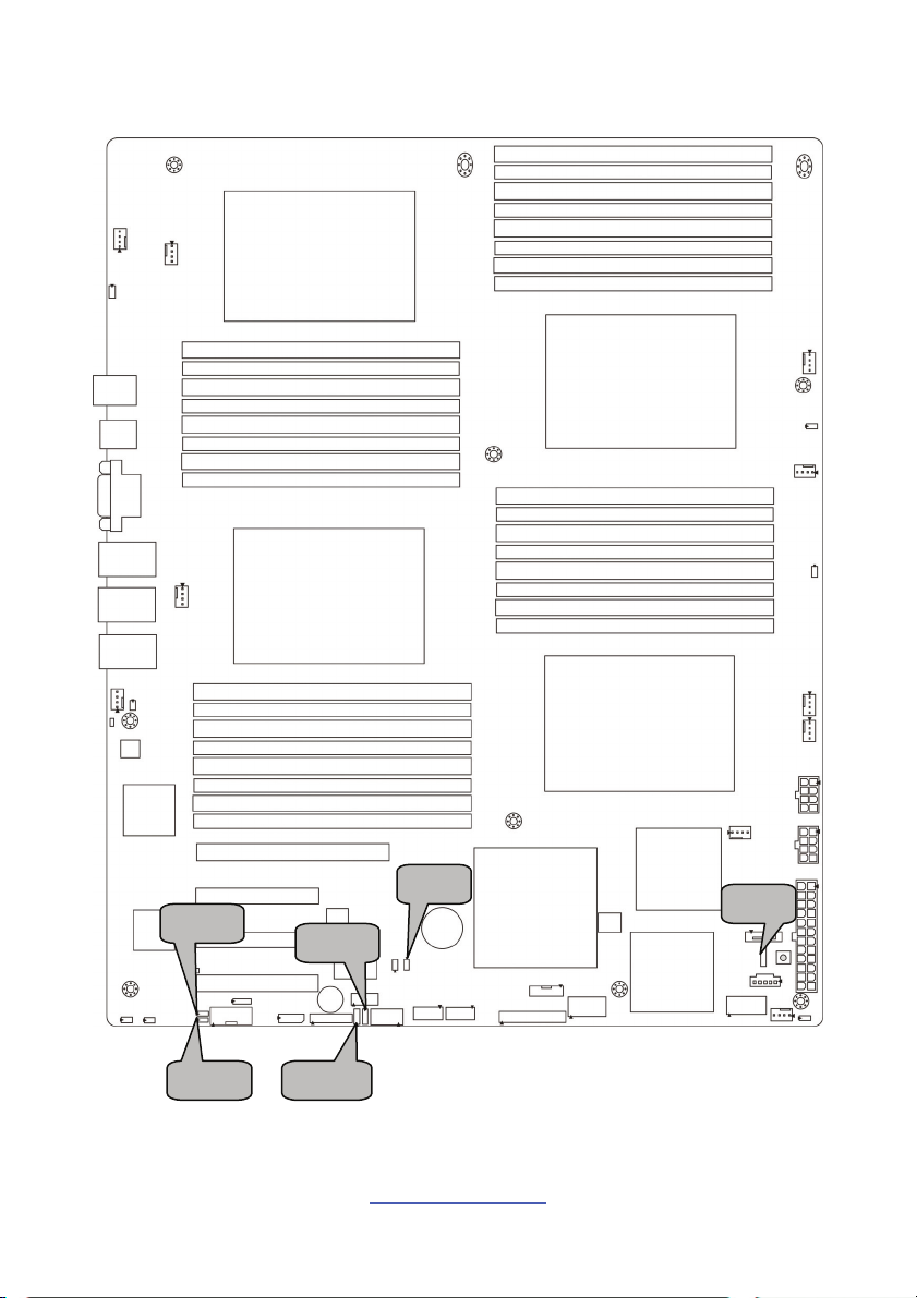
J24
J10
J14
J15
J9
J23
J8
J6
J18
12
http://www.tyan.com
J66
J55
J21
J25
J22
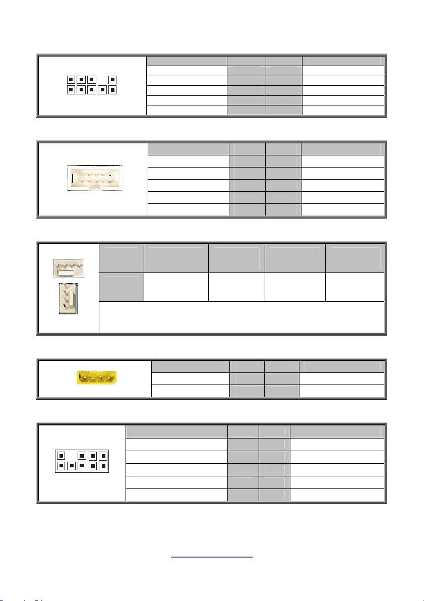
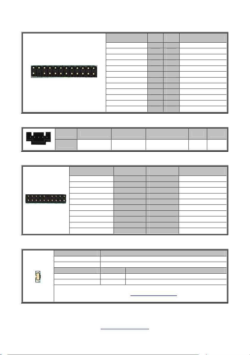
J6: CPLD JTAG Connector
0
9
092
2
1
1
Signal Pin Pin Signal
TCK 1 2 GND
TDO 3 4 V3DU
TMS 5 6 NC
NC 7 8 KEY
TDI 9 10 GND
J8: COM2 Connector
Signal Pin Pin Signal
DCD 1 2 SER
RXD 3 4 RTS
TXD 5 6 CTS
DTR 7 8 RI
GND 9 10 NC
J9/J10/J14/J15/J21/J22/J23/J24/J25/J55: 4-Pin FAN Connectors
Pin 1 2 3 4
Signal GND +12V TACH PWM
Use this header to connect the cooling fan to your motherboard to keep the
system stable and reliable.
J18: IPMB Connector
Signal Pin Pin Signal
IPMB DATA 1 2 GND
IPMB CLK 3 4 NC
J66: SAS Fault LED
Signal Pin Pin Signal
1
LED_SAS_FAULT-0 1 2 LED_SAS_FAULT-1
LED_SAS_FAULT-2 3 4 LED_SAS_FAULT-3
LED_SAS_FAULT-4 5 6 LED_SAS_FAULT-5
1
KEY 7 8 LED_SAS_FAULT-7
LED_SAS_FAULT-6 9 10 GND
http://www.tyan.com
13
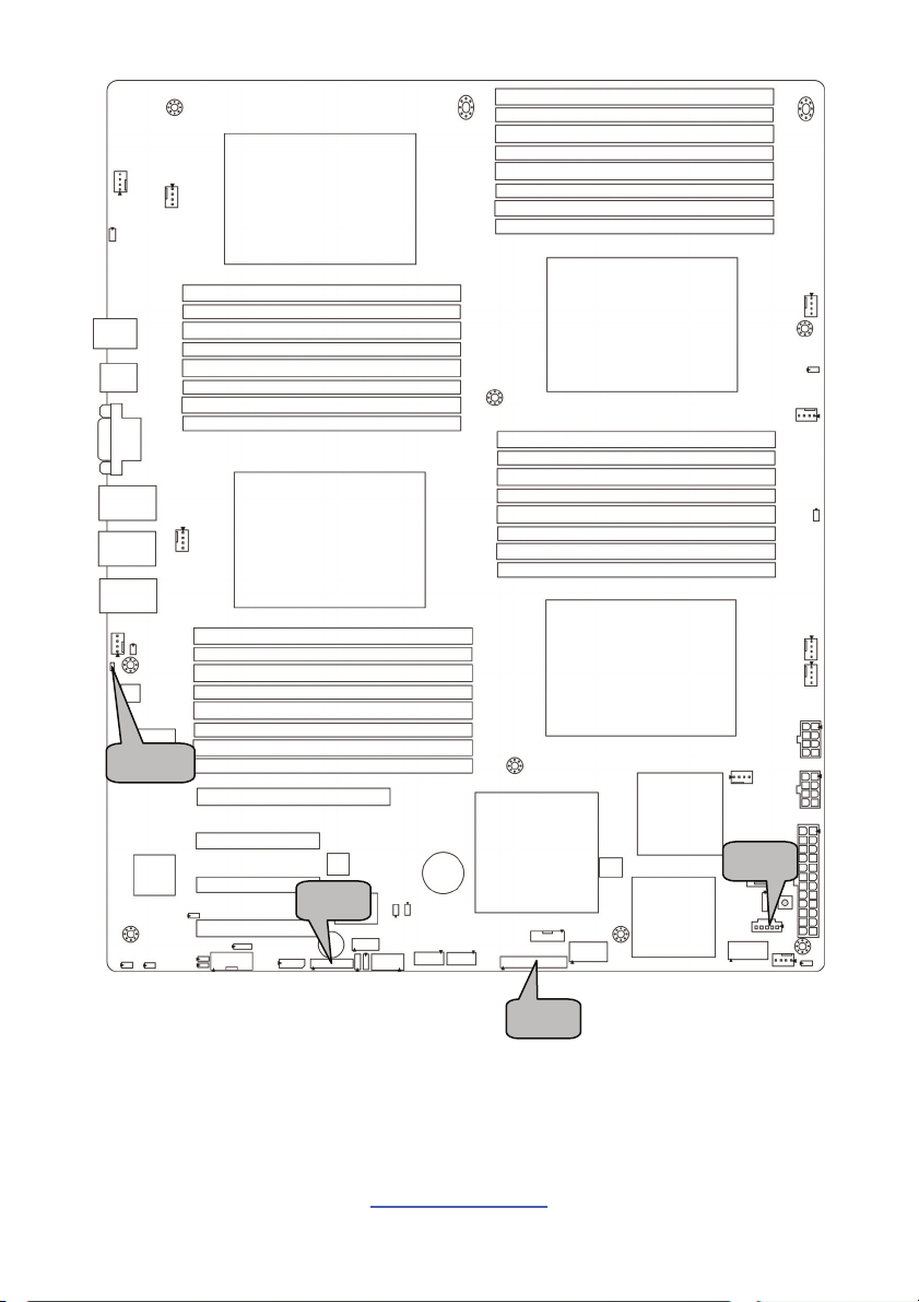
LED1
J88
J89
http://www.tyan.com
14
J64
J64: Front Panel Connector
J88: PSMI Connector
Pin 1 2 3 4 5
Signal SMB_SCLK SMB_SDAT SMB_ALERT_L GND VCC3
J89: Fan TACH Connector
Signal Pin Pin Signal
Taco 1 1 2 Taco 6
Taco 2 3 4 Taco 7
Taco 3 5 6 Taco 8
Taco 4 7 8 Taco 9
Taco 5 9 10 Taco 10
GND 11 12 KEY
PWM2 13 14 PWM1
Taco 11 15 16 NC
Taco 12 17 18 NC
NC 19 20 PWM3
Signal Pin Pin Signal
Power LED+ 1 2 FP_PWR
KEY 3 4 IDLED+
Power LED - 5 6 IDLED-
HD LED+ 7 8 WARN_LEDHD LED - 9 10 PSU_ALERT-
Power SW 11 12 LAN1_LED+
GND 13 14 LAN1_LED-
Reset SW 15 16 SDA
GND 17 18 SCL
ID SW 19 20 INTRUDER_L
TEMP Sensor 21 22 LAN2_LED+
NMI 23 24 LAN2_LED-
LED1: ID LED
+
_
Pin Signal
+ P3V3_AUX
- ID_SW_L
State Color Description
On Blue System identified
Off Off System not identified
NOTE: IPMI can activate ID LED from remote site.
Please visit the TYAN Web Site at http://www.tyan.com
latest AST2050 Software Configuration Guide for IPMI settings.
to download the
15
http://www.tyan.com
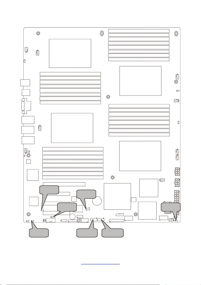
JP7
JP13
JP10
JP12
JP11
16
http://www.tyan.com
JP8
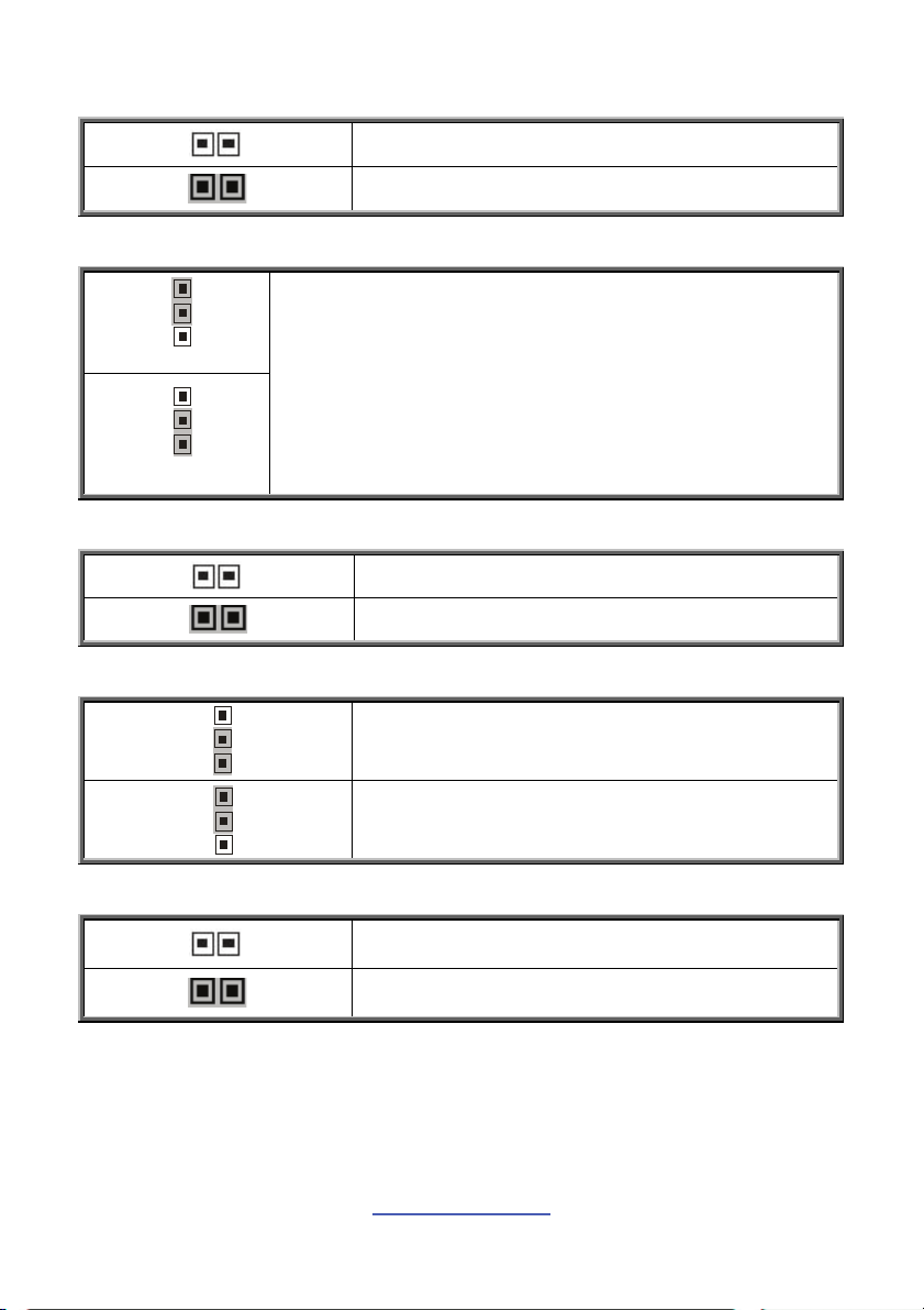
JP7: PCI-E x8/x16 Select Jumper
Open: PCI-E x16 (slot #4) (Default)
Closed: PCI-E x8 (slot #4) + PCI-E x8 (slot #3)
JP8: Clear CMOS Jumper
1
3
Normal (Default)
1
You can reset CMOS by using this jumper if you have
forgotten your system/setup password or need to clear BIOS
setting.
1. Power off system and disconnect both power connectors
from the motherboard.
2. Put jumper cap back to Pin_1 and Pin_2 (default setting).
3. Use jumper cap to close Pin_2 and Pin_3 for seconds to
3
Clear CMOS
Clear CMOS.
4. Reconnect power & power on system.
JP10: BMC Disable Jumper
Open: Normal (Default)
Closed: BMC Disable
JP11/JP12: COM2 Switch Jumper
3
Pin 1-2 Closed: SIO to COM2 (Default)
1
3
Pin 2-3 Closed: BMC UART2 to COM2
1
JP13: TPM Disable Jumper
Open: Enable TPM (Default)
Closed: Disable TPM
17
http://www.tyan.com
JP19
JP14 JP16
JP15
JP24
USB1 USB2
18
http://www.tyan.com
JP14: COM Power Select Jumper
1
1
3
3
Pin 1-2 Closed: VCC (Default)
Pin 2-3 Closed: V5SB
JP15: WDT Trigger NMI Jumper
Open: WDT Reset System (Default)
Closed: WDT Trigger NMI
JP16: Chassis Intrusion Header
Use this header to trigger the system chassis
1
intrusion alarm.
JP19: VGA Disable Jumper
Open: Enable VGA (Default)
Closed: Disable VGA
JP24: LAN3 LED Header
Pin Signal
1 LAN3 LED+
1
2 LAN3 LED-
USB1/USB2: USB Front Panel Connector
Signal Pin Pin Signal
VCC 1 2 VCC
USB0- 3 4 USB1USB0+ 5 6 USB1+
GND 7 8 GND
KEY 9 10 NC
http://www.tyan.com
19
JP25
JP22
JP27
JP26
JP21
http://www.tyan.com
20
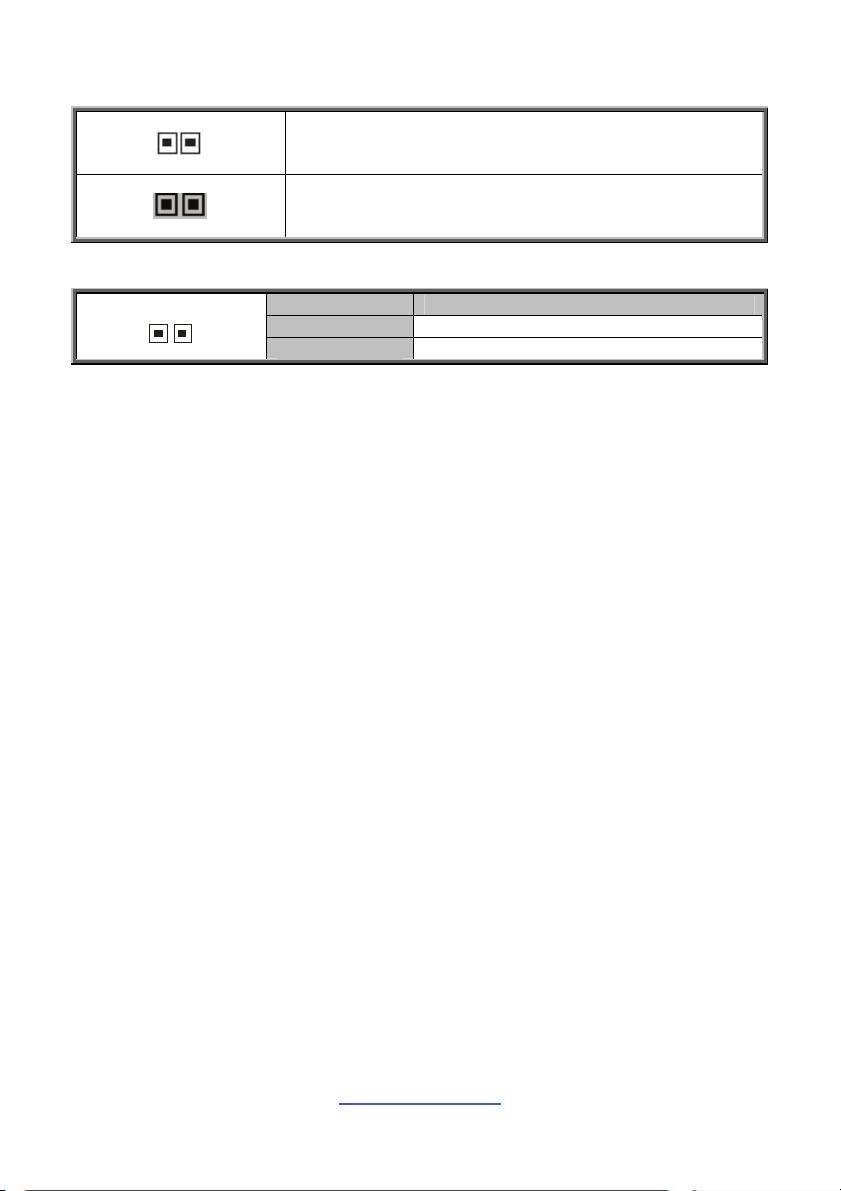
JP21/JP22/JP25/JP26: DDR3 VDDIO Voltage Select Jumper
JP27: ID LED Connector
1
Open: Support regular 1.5V DDR3 memory (Default)
Closed: Support for Low Voltage 1.35V DDR3 memory
Pin Signal
1 ID LED+
2 GND
http://www.tyan.com
21
2.4 Installing the Processor and Heat sink
The S8812 supported AMD® processors are listed in section 1.2 Hardware
Specifications on page 4. Check our website at http://www.tyan.com
for latest
processor support.
NOTE: MiTAC is not liable for damage as a result of operating an
unsupported configuration.
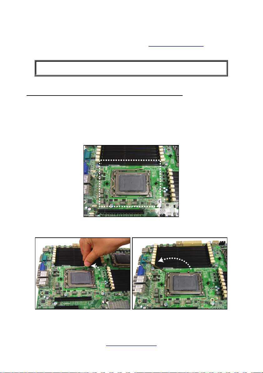
Processor Installation (G34 1944-pin Socket for AMD CPU)
Follow the steps below to install the processors and heat sinks.
Please note that the illustrations are based on a G34 1944-pin Socket which may
be look exactly like the motherboard you purchased. Therefore, the illustrations
should be held for your reference only.
1. Locate the CPU socket.
2. Pull the CPU lever slightly away from the socket and then push it to a fully
open position.
http://www.tyan.com
22
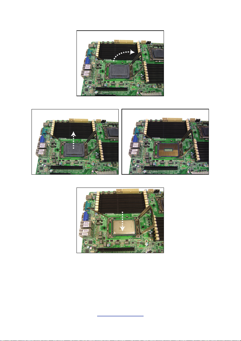
3. Lift the socket cover to a fully open position.
4. Take off the CPU protection cap.
5. Place the CPU in the CPU socket.
http://www.tyan.com
23
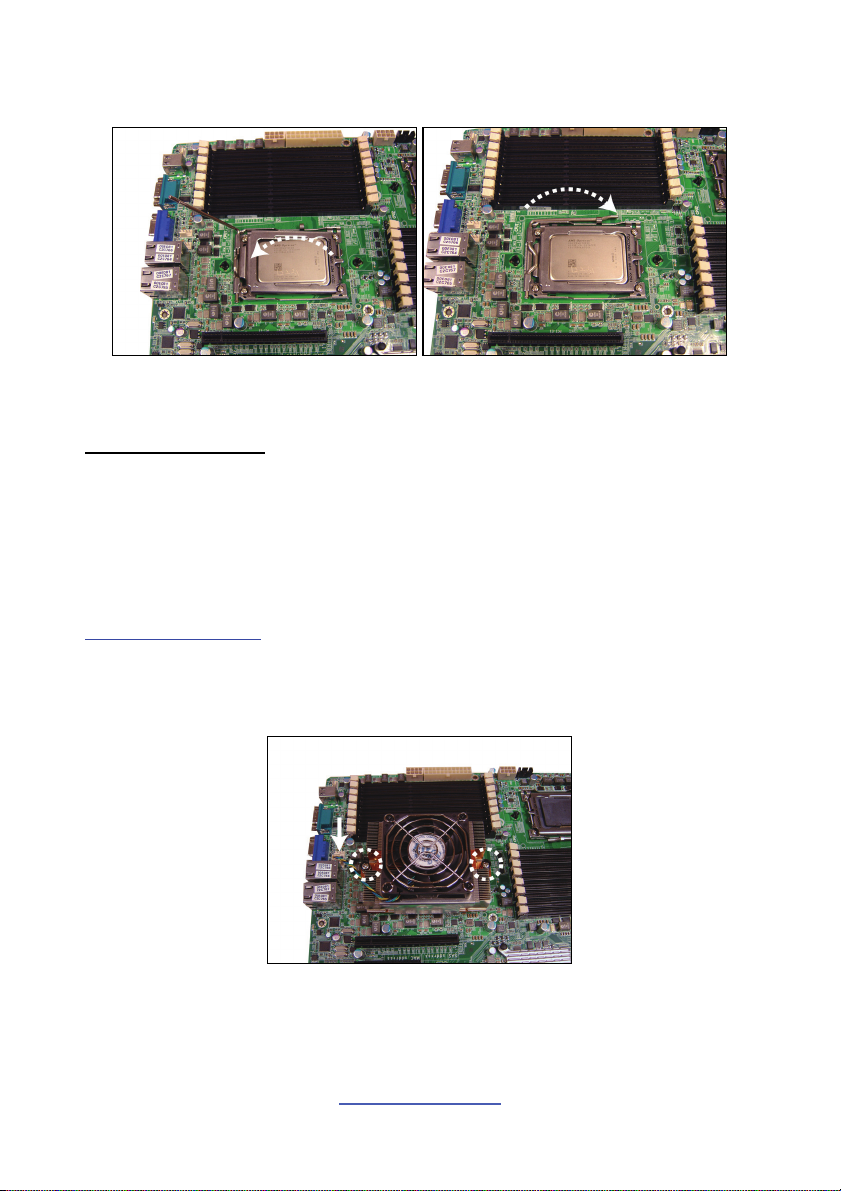
6. Close the socket cover and press the CPU socket lever down to lock the CPU
in place.
7. Repeat the same procedures to install the other CPUs.
Heat sink Installation
After installing the processor, you should proceed to install the heat sink. The CPU
heat sink will ensure that the processor do not overheat and continue to operate at
maximum performance for as long as you own them. The overheated processor is
dangerous to the motherboard.
For the safest method of installation and information on choosing the appropriate
heat sink, using heat sinks validated by AMD
http://www.amd.com
®
. Please refer to the AMD® website:
The following diagram illustrates how to install heat sink onto the CPU of S8812.
8. Place the heat sink on top of the CPU and secure it to the motherboard with 2
screws.
9. Connect the heat sink Fan cable to the CPU0 FAN connector J55.
10. Repeat the same procedures to install the other heat sinks (CPU1 Fan: J9,
CPU2 Fan: J10, CPU3 Fan: J14).
http://www.tyan.com
24
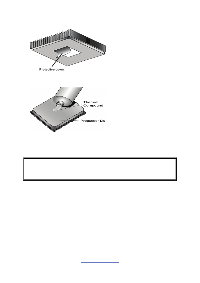
2.5 Thermal Interface Material
There are two types of
thermal interface materials
designed for use with the
processors.
The most common material
comes as a small pad
attached to the heat sink at
the time of purchase. There
should be a protective cover
over the material. Take care
not to touch this material.
Simply remove the protective
cover and place the heat
sink on the processor.
The second type of interface
material is usually packaged
separately. It is commonly
referred to as ‘thermal
compound’. Simply apply a
thin layer on to the CPU lid
(applying too much will
actually reduce the cooling).
NOTE: Always check with the manufacturer of the heat sink & processor to
ensure that the thermal interface material is compatible with the processor
and meets the manufacturer’s warranty requirements.
http://www.tyan.com
25
2.6 Tips on Installing Motherboard in Chassis
Before installing your motherboard, make sure your chassis has the necessary
motherboard support studs installed. These studs are usually metal and are gold in
color. Usually, the chassis manufacturer will pre-install the support studs. If you are
unsure of stud placement, simply lay the motherboard inside the chassis and align
the screw holes of the motherboard to the studs inside the case. If there are any
studs missing, you will know right away since the motherboard will not be able to be
securely installed.
http://www.tyan.com
26
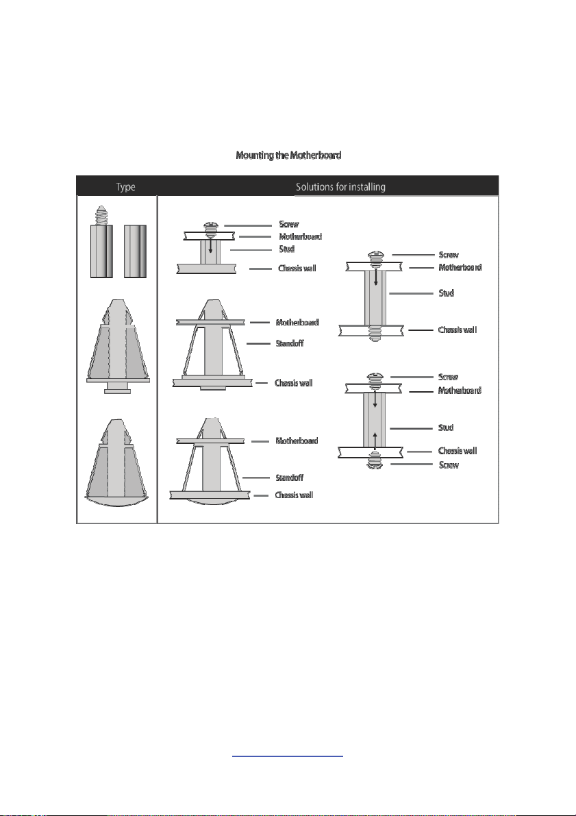
Some chassis include plastic studs instead of metal. Although the plastic studs are
usable, MiTAC recommends using metal studs with screws that will fasten the
motherboard more securely in place.
Below is a chart detailing what the most common motherboard studs look like and
how they should be installed.
http://www.tyan.com
27
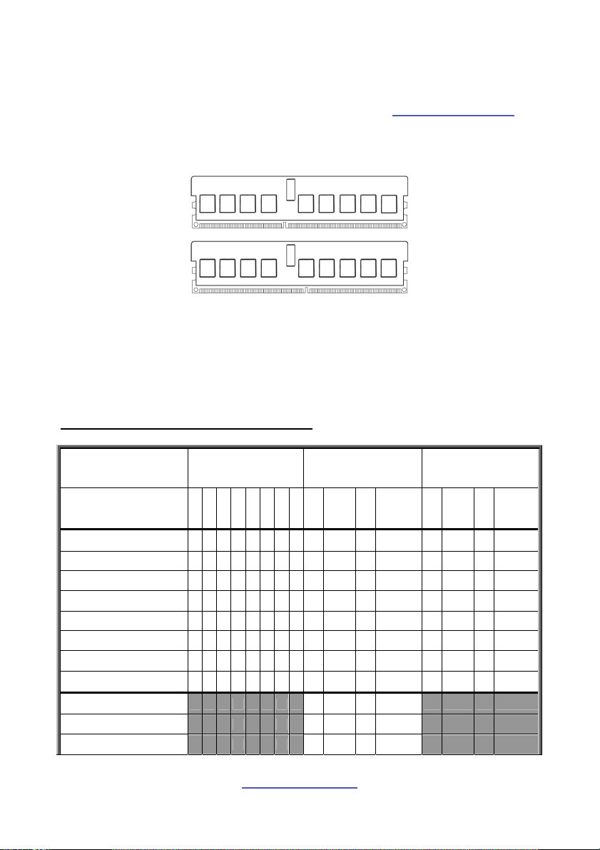
2.7 Installing the Memory
Before installing memory, ensure that the memory you have is compatible with the
motherboard and processor. Check the TYAN Web site at http://www.tyan.com
details of the type of memory recommended for your motherboard.
The following diagram shows common types of DDR3 memory modules.
for
Supports up to 256GB total of U/RDDR3 and LV RDDR3 at 800,1066 or
1333MHz speeds
All installed memory will automatically be detected and no jumpers or settings
need changing
All memory must be of the same type and density
Always populate the memory starting from P0_DIMMA1 first
Recommended Memory Population Table
Quantity of
memory installed
P0_DIMM(1)D0 √ √ √
P0_DIMM(2)D1 √ √ √ √ √ √ √ √
P0_DIMM(3)C0 √ √ √
P0_DIMM(4)C1 √ √ √ √ √ √ √ √
P0_DIMM(5)B0 √ √ √
P0_DIMM(6)B1 √ √ √ √ √ √ √ √
P0_DIMM(7)A0 √ √ √
P0_DIMM(8)A1 √ √ √ √ √ √ √ √
P1_DIMM(9)D0 √
P1_DIMM(10)D1 √ √
P1_DIMM(11)C0 √
Single CPU
Installed
(CPU0 only)
11112248 8 16 8 16
28
http://www.tyan.com
Dual CPU
installed
(CPU0 and CPU1)
Dual CPU
installed
(CPU0 and CPU3)
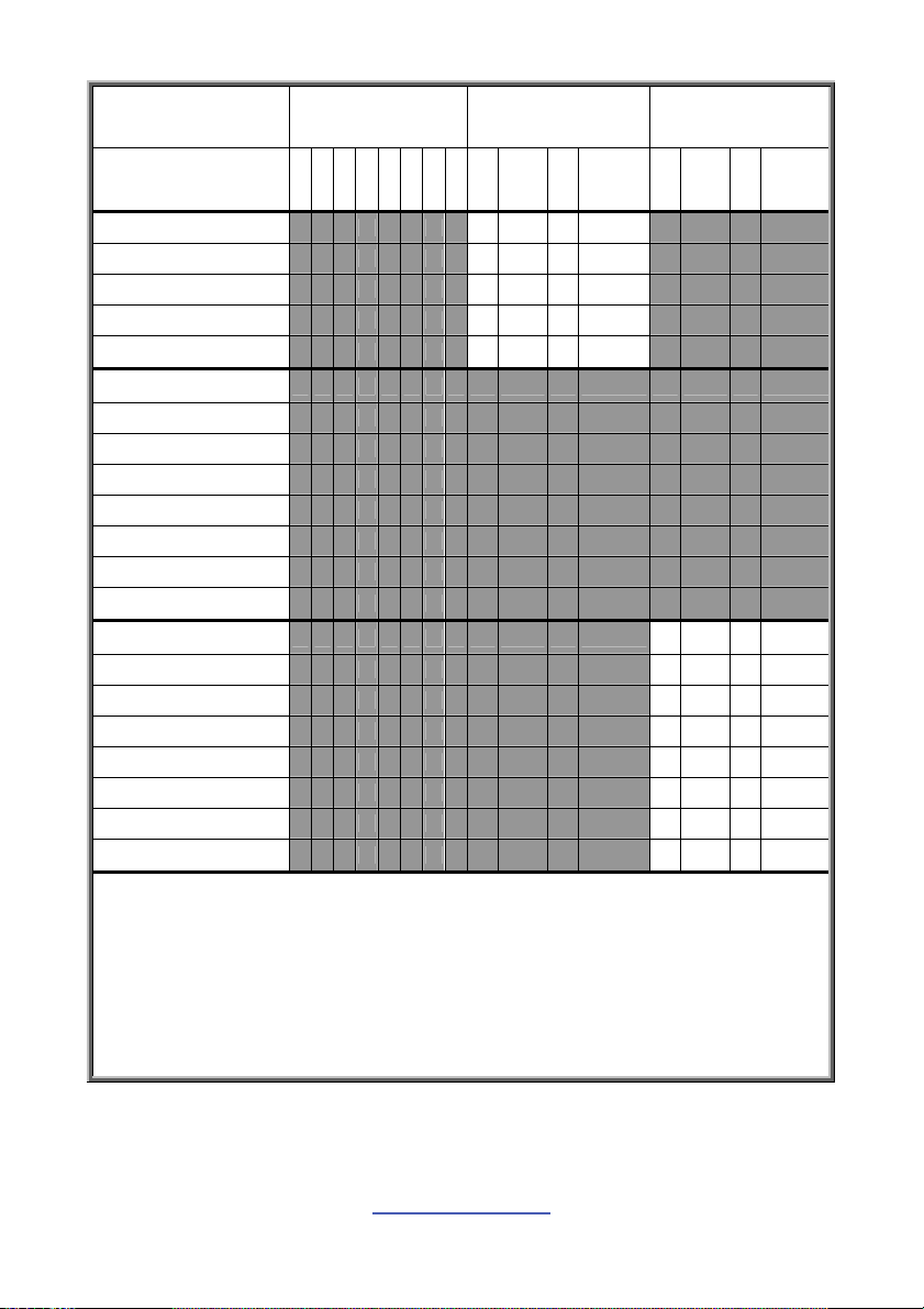
Quantity of
memory installed
P1_DIMM(12)C1 √ √
P1_DIMM(13)B0 √
P1_DIMM(14)B1 √ √
P1_DIMM(15)A0 √
P1_DIMM(16)A1 √ √
P2_DIMM(17)D0
P2_DIMM(18)D1
P2_DIMM(19)C0
P2_DIMM(20)C1
P2_DIMM(21)B0
P2_DIMM(22)B1
P2_DIMM(23)A0
P2_DIMM(24)A1
P3_DIMM(25)D0 √
P3_DIMM(26)D1 √ √
P3_DIMM(27)C0 √
P3_DIMM(28)C1 √ √
P3_DIMM(29)B0 √
P3_DIMM(30)B1 √ √
P3_DIMM(31)A0 √
P3_DIMM(32)A1 √ √
Single CPU
Installed
(CPU0 only)
11112248 8 16 8 16
Dual CPU
installed
(CPU0 and CPU1)
Dual CPU
installed
(CPU0 and CPU3)
NOTE:
1. √ indicates a populated DIMM slot.
2. Paired memory installation for Max performance.
3. One or two or four menorys with Dual CPUs,memory install refer to Single CPU.
4. One or two or four menorys with Triple CPUs,memory install refer to Single CPU.
5. One or two or four menorys with Quad CPUs,memory install refer to Single CPU.
6. We don't suggest other memory installation.
http://www.tyan.com
29
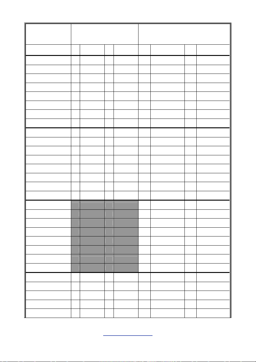
Quantity of
memory installed
P0_DIMM(1)D0 √ √
P0_DIMM(2)D1 √ √ √ √
P0_DIMM(3)C0 √ √
P0_DIMM(4)C1 √ √ √ √
P0_DIMM(5)B0 √ √
P0_DIMM(6)B1 √ √ √ √
P0_DIMM(7)A0 √ √
P0_DIMM(8)A1 √ √ √ √
P1_DIMM(9)D0 √ √
P1_DIMM(10)D1 √ √ √ √
P1_DIMM(11)C0 √ √
P1_DIMM(12)C1 √ √ √ √
P1_DIMM(13)B0 √ √
P1_DIMM(14)B1 √ √ √ √
P1_DIMM(15)A0 √ √
P1_DIMM(16)A1 √ √ √ √
P2_DIMM(17)D0 √
P2_DIMM(18)D1 √ √
P2_DIMM(19)C0 √
P2_DIMM(20)C1 √ √
P2_DIMM(21)B0 √
P2_DIMM(22)B1 √ √
P2_DIMM(23)A0 √
P2_DIMM(24)A1 √ √
P3_DIMM(25)D0 √ √
P3_DIMM(26)D1 √ √ √ √
P3_DIMM(27)C0 √ √
P3_DIMM(28)C1 √ √ √ √
P3_DIMM(29)B0 √ √
12 24 16 32
Triple CPU
installed
(CPU0 and CPU1 and CPU3)
(CPU0 and CPU1 and CPU2 and CPU3)
Quad CPU
installed
http://www.tyan.com
30
 Loading...