

TYAN S8232 User Manual

S8232
Version 1.2
Copyright
Copyright © 2011 MiTAC International Corporation. All rights reserved. No part of
this manual may be reproduced or translated without prior written consent from
MiTAC International Corporation.
Trademark
All registered and unregistered trademarks and company names contained in this
manual are property of their respective owners including, but not limited to the
following.
TYAN® is a trademark of MiTAC International Corporation.
AMD
®
is a trademark of AMD® Corporation.
Intel
®
is a trademark of Intel® Corporation.
AMI, AMI BIOS are trademarks of AMI Technologies.
Microsoft®, Windows® are trademarks of Microsoft Corporation.
Winbond
®
is a trademark of Winbond Electronics Corporation.
Notice
Information contained in this document is furnished by MiTAC International
Corporation and has been reviewed for accuracy and reliability prior to printing.
MiTAC assumes no liability whatsoever, and disclaims any express or implied
warranty, relating to sale and/or use of TYAN
®
products including liability or
warranties relating to fitness for a particular purpose or merchantability. MiTAC
retains the right to make changes to product descriptions and/or specifications at
any time, without notice. In no event will MiTAC be held liable for any direct or
indirect, incidental or consequential damage, loss of use, loss of data or other
malady resulting from errors or inaccuracies of information contained in this
document.

http://www.tyan.com
2

Contents
Before you begin….................................................................................... 4
Chapter 1: Instruction ................................................................................5
1.1 Congratulations .................................................................................5
1.2 Hardware Specifications ..................................................................5
1.3 Software Specifications ................................................................... 12
Chapter 2: Board Installation................................................................... 13
2.1 Board Image ....................................................................................14
2.2 Block Diagram ................................................................................. 15
2.3 Board Parts, Jumpers and Connectors ........................................... 16
2.4 Installing the Processor and Heat sink............................................28
2.5 Thermal Interface Material ..............................................................31
2.6 Tips on Installing Motherboard in Chassis ...................................... 32
2.7 Installing the Memory ...................................................................... 34
2.8 Attaching Drive Cables ....................................................................37
2.9 Installing Add-In Cards .................................................................... 38
2.10 Connecting External Devices ........................................................ 39
2.11 Installing the Power Supply ........................................................... 40
2.12 Finishing Up................................................................................... 42
Chapter 3: BIOS Setup ............................................................................. 43
3.1 About the BIOS................................................................................ 43
3.2 Main Menu....................................................................................... 45
3.3 Advanced Menu............................................................................... 46
3.4 PCI/PnP Menu................................................................................. 69
3.5 Boot Menu ....................................................................................... 71
3.6 Security Menu.................................................................................. 73
3.7 Chipset Menu ..................................................................................75
3.8 Exit Menu......................................................................................... 82
Chapter 4: Diagnostics............................................................................. 83
4.1 Beep Codes..................................................................................... 83
4.2 Flash Utility ......................................................................................83
4.3 AMIBIOS Post Code........................................................................ 84
Glossary..................................................................................................... 87

http://www.tyan.com
4
Before you begin…
Check the box contents!
The retail motherboard package should contain the following:
1x S8232 Motherboard
6 x Serial ATA Cable
1 x USB2.0 cable
1 x S8232 User’s manual
1 x S8232 Quick reference guide
1 x TYAN® Driver CD
1 x I/O shield
2 x mini SAS Cable
(for S8232WGM4NR/S8232WAG2NRF-LE only)

http://www.tyan.com
5
Chapter 1: Instruction
1.1 Congratulations
You have purchased the powerful TYAN® S8232 motherboard, based on the
AMD
®
SP5100 chipset. The S8232 is designed to support dual AMD® 45nm 8Core/12-Core Opteron 6100 Series Processors and up to 256GB RDIMM or
64GB UDIMM of 800, 1066 and 1333MHz DDR3 memory, as well as low-voltage
DDR3 memory modules. Leveraging advanced technology from AMD
®
, the
S8232 is capable of offering scalable 32 and 64-bit computing, high-bandwidth
memory design, and lightning-fast PCI-E bus implementation.
The S8232 not only empowers you in today’s demanding IT environment but also
offers a smooth path for future application upgradeability. All of these rich feature
sets provides the S8232 with the power and flexibility to meet demanding
requirements for today’s IT environments.
Remember to visit the TYAN® website at http://www.tyan.com. There you can
find all the information on all TYAN® products as well as all the supporting
documentation, FAQs, Drivers and BIOS upgrades.
1.2 Hardware Specifications
TYAN S8232 (S8232WGM4NR)
Supported CPU
Series
AMD 45nm 8-Core/12-Core Opteron 6100 Series
Processors (Magny-Cours) / HT3.0 support ; 12MB L3
per socket
Socket Type / Q'ty G34 / (2)
Average CPU Power
(ACP) wattage
Up to 105W
Processor
System Bus Up to 6.4 GT/s Hyper-Transport link support
Chipset AMD (2)SR5690 + SP5100
Chipset
Super I/O Winbond W83627
Supported DIMM Qty (12)+(12) DIMM slots
DIMM Type / Speed U/RDDR3 & LV RDDR3, 800/1066/1333 MHz
Capacity Up to 256GB RDIMM/ 64GB UDIMM
Memory channel 4 Channels per CPU
Memory
Memory voltage 1.5V or 1.35V
PCI-E
(2) PCI-E Gen.2 x8 slots (x4 link) / (4) PCI-E Gen.2
x16 slots
Expansion
Slots
PCI (1) PCI 32-bit slot
Port Q'ty (4)
LAN
Controller Intel 82576EB
Storage SAS
Connector (2) Mini-SAS connectors (2x (4-in-1) connectors)
http://www.tyan.com
6
Controller LSI SAS2008
Speed 6.0 Gb/s
RAID RAID 0/1/1E/10 (LSI Integrated RAID)
Connector (6) SATA
Controller AMD SP5100
Speed 3.0 Gb/s
SATA
RAID RAID 0/1/10/5 (Promise Integrated Software RAID)
Connector type D-Sub 15-pin
Resolution 1600x1200@60Hz
Graphic
Chipset Aspeed AST2050
Chipset Infineon SLB9635
TPM
Version TPM v1.2
USB
(9) USB2.0 ports (4 at rear, 4 via cable, 1 type A
onboard)
COM (2) ports (1 at rear, 1 via cable)
SAS (2) Mini-SAS (4-in-1) connectors
VGA (1) D-Sub 15-pin VGA port
RJ-45 (4) GbE ports
Power
Universal 24-pin + 8-pin + 8-pin + 4-pin power
connectors / SSI EEB Spec V.96
Front Panel (1) 2x12-pin SSI front panel header
Input /Output
SATA (6) SATA-II connectors
Chipset Winbond W83795G
Voltage
Monitors voltage for CPU, memory, chipset & power
supply
Fan Total (8) 4-pin headers
Temperature Monitors temperature for CPU & system environment
LED
Fan fail LED indicator / Over temperature warning
indicator / Fan & PSU fail LED indicator
System
Monitoring
Others Watchdog timer support
Onboard Chipset Onboard Aspeed AST2050
AST2050 IPMI
Feature
IPMI 2.0 compliant baseboard management controller
(BMC) / USB 2.0 virtual hub / BIOS update
Server
Management
AST2050 iKVM
Feature
24-bit high quality video compression / Dual 10/100
Mb/s MAC interfaces
Brand / ROM size AMI / 4MB
BIOS
Feature
Plug and Play (PnP) /PCI2.3 /WfM2.0 /SMBIOS2.3
/PXE boot / ACPI 2.0 power management /Power on
mode after power recovery / User-configurable H/W
monitoring
Form Factor MEB
Physical
Dimension
Board Dimension 13" x 16" (330 x 406mm)
Operating
System
OS supported list Please visit our Web site for the latest update.
http://www.tyan.com
7
FCC (DoC) Class A
Regulation
CE (DoC) Yes
Operating Temp. 10° C ~ 35° C (50° F~ 95° F)
Non-operating
Temp.
- 40° C ~ 70° C (-40° F ~ 158° F)
Operating
Environment
In/Non-operating
Humidity
90%, non-condensing at 35° C
RoHS RoHS 6/6 Complaint Yes
Motherboard (1) S8232 Motherboard
Manual (1) User's manual / (1) Quick Ref. Guide
Installation CD (1) TYAN installation CD
I/O Shield (1) I/O Shield
SATA (6) SATA signal cables
Package
Contains
Cable
SAS (2) Mini-SAS cables (2x (4-in-1) connectors)
TYAN S8232 (S8232GM4NR)
Supported CPU
Series
AMD 45nm 8-Core/12-Core Opteron 6100 Series
Processors (Magny-Cours) / HT3.0 support ; 12MB L3
per socket
Socket Type / Q'ty G34 / (2)
Average CPU Power
(ACP) wattage
Up to 105W
Processor
System Bus Up to 6.4 GT/s Hyper-Transport link support
Chipset AMD (2)SR5690 + SP5100
Chipset
Super I/O Winbond W83627
Supported DIMM Qty (12)+(12) DIMM slots
DIMM Type / Speed U/RDDR3 & LV RDDR3, 800/1066/1333 MHz
Capacity Up to 256GB RDIMM/ 64GB UDIMM
Memory channel 4 Channels per CPU
Memory
Memory voltage 1.5V or 1.35V
PCI-E
(2) PCI-E Gen.2 x8 slots (x4 link) / (4) PCI-E Gen.2
x16 slots
Expansion
Slots
PCI (1) PCI 32-bit slot
Port Q'ty (4)
LAN
Controller Intel 82576EB
Connector (6) SATA
Controller AMD SP5100
Speed 3.0 Gb/s
Storage SATA
RAID RAID 0/1/10/5 (Promise Integrated Software RAID)
Connector type D-Sub 15-pin
Resolution 1600x1200@60Hz
Graphic
Chipset Aspeed AST2050
http://www.tyan.com
8
Chipset Infineon SLB9635
TPM
Version TPM v1.2
USB
(9) USB2.0 ports (4 at rear, 4 via cable, 1 type A
onboard)
COM (2) ports (1 at rear, 1 via cable)
VGA (1) D-Sub 15-pin VGA port
RJ-45 (4) GbE ports
Power
Universal 24-pin + 8-pin + 8-pin + 4-pin power
connectors / SSI EEB Spec V.96
Front Panel (1) 2x12-pin SSI front panel header
Input /Output
SATA (6) SATA-II connectors
Chipset Winbond W83795G
Voltage
Monitors voltage for CPU, memory, chipset & power
supply
Fan Total (8) 4-pin headers
Temperature Monitors temperature for CPU & system environment
LED
Fan fail LED indicator / Over temperature warning
indicator / Fan & PSU fail LED indicator
System
Monitoring
Others Watchdog timer support
Onboard Chipset Onboard Aspeed AST2050
AST2050 IPMI
Feature
IPMI 2.0 compliant baseboard management controller
(BMC) / USB 2.0 virtual hub / BIOS update
Server
Management
AST2050 iKVM
Feature
24-bit high quality video compression / Dual 10/100
Mb/s MAC interfaces
Brand / ROM size AMI / 4MB
BIOS
Feature
Plug and Play (PnP) /PCI2.3 /WfM2.0 /SMBIOS2.3
/PXE boot / ACPI 2.0 power management /Power on
mode after power recovery / User-configurable H/W
monitoring
Form Factor MEB
Physical
Dimension
Board Dimension 13" x 16" (330 x 406mm)
Operating
System
OS supported list Please visit our Web site for the latest update.
FCC (DoC) Class A
Regulation
CE (DoC) Yes
Operating Temp. 10° C ~ 35° C (50° F~ 95° F)
Non-operating
Temp.
- 40° C ~ 70° C (-40° F ~ 158° F)
Operating
Environment
In/Non-operating
Humidity
90%, non-condensing at 35° C
RoHS RoHS 6/6 Complaint Yes
Motherboard (1) S8232 Motherboard
Manual (1) User's manual / (1) Quick Ref. Guide
Package
Contains
Installation CD (1) TYAN installation CD
http://www.tyan.com
9
I/O Shield (1) I/O Shield
Cable SATA (6) SATA signal cables
TYAN S8232 (S8232WAG2NRF-LE)
Supported CPU
Series
AMD 45nm 8-Core/12-Core Opteron 6100 Series
Processors (Magny-Cours) / HT3.0 support ; 12MB L3
per socket
Socket Type / Q'ty G34 / (2)
Average CPU Power
(ACP) wattage
Up to 105W
Processor
System Bus Up to 6.4 GT/s Hyper-Transport link support
Chipset AMD SR5690 + SP5100
Chipset
Super I/O Winbond W83627
Supported DIMM Qty (12)+(12) DIMM slots
DIMM Type / Speed U/RDDR3 & LV RDDR3, 800/1066/1333 MHz
Capacity Up to 256GB RDIMM/ 64GB UDIMM
Memory channel 4 Channels per CPU
Memory
Memory voltage 1.5V or 1.35V
PCI-E (2) PCI-E Gen.2 x16 slots
Expansion
Slots
PCI (1) PCI 32-bit slot
Port Q'ty (2)
LAN
Controller Intel 82576EB
Connector (2) Mini-SAS connectors (2x (4-in-1) connectors)
Controller LSI SAS2008
Speed 6.0 Gb/s
SAS
RAID RAID 0/1/1E/10 (LSI Integrated RAID)
Connector (6) SATA
Controller AMD SP5100
Speed 3.0 Gb/s
Storage
SATA
RAID RAID 0/1/10/5 (Promise Integrated Software RAID)
Connector type D-Sub 15-pin
Resolution 1600x1200@60Hz
Graphic
Chipset Aspeed AST1100
Chipset Realtek ALC262
Audio
Feature High Definition Audio
Port Q'ty (2)
FireWire
Chipset VIA VT6308
USB
(9) USB2.0 ports (4 at rear, 4 via cable, 1 type A
onboard)
COM (2) ports (1 at rear, 1 via cable)
SAS (2) Mini-SAS (2x (4-in-1) connectors)
Input /Output
VGA (1) D-Sub 15-pin VGA port
http://www.tyan.com
10
Audio
(1) 2x5-pin front panel audio header / (1) 2x6-pin rear
audio jack header
RJ-45 (2) GbE ports
Firewire (1) 2x5-pin header
Power
Universal 24-pin + 8-pin + 8-pin + 4-pin power
connectors / SSI EEB Spec V.96
Front Panel (1) 2x12-pin SSI front panel header
SATA (6) SATA-II connectors
Chipset Winbond W83795G
Voltage
Monitors voltage for CPU, memory, chipset & power
supply
Fan Total (8) 4-pin headers
Temperature Monitors temperature for CPU & system environment
LED
Fan fail LED indicator / Over temperature warning
indicator / Fan & PSU fail LED indicator
System
Monitoring
Others Watchdog timer support
Brand / ROM size AMI / 4MB
BIOS
Feature
Plug and Play (PnP) /PCI2.3 /WfM2.0 /SMBIOS2.3
/PXE boot / ACPI 2.0 power management /Power on
mode after power recovery / User-configurable H/W
monitoring
Form Factor MEB
Physical
Dimension
Board Dimension 13" x 16" (330 x 406mm)
Operating
System
OS supported list Please visit our Web site for the latest update.
FCC (DoC) Class A
Regulation
CE (DoC) Yes
Operating Temp. 10° C ~ 35° C (50° F~ 95° F)
Non-operating
Temp.
- 40° C ~ 70° C (-40° F ~ 158° F)
Operating
Environment
In/Non-operating
Humidity
90%, non-condensing at 35° C
RoHS RoHS 6/6 Complaint Yes
Motherboard (1) S8232 Motherboard
Manual (1) User's manual / (1) Quick Ref. Guide
Installation CD (1) TYAN installation CD
I/O Shield (1) I/O Shield
SATA (6) SATA signal cables
SAS (2) Mini-SAS cables
IEEE1394 (1) CCBL-1030, 2-port IEEE 1394a bracket cable
Package
Contains
Cable
Audio (1) CCBL-0613, 3-POS audio bracket cable
http://www.tyan.com
11
TYAN S8232 (S8232AG2NRF-LE)
Supported CPU
Series
AMD 45nm 8-Core/12-Core Opteron 6100 Series
Processors (Magny-Cours) / HT3.0 support ; 12MB L3
per socket
Socket Type / Q'ty G34 / (2)
Average CPU Power
(ACP) wattage
Up to 105W
Processor
System Bus Up to 6.4 GT/s Hyper-Transport link support
Chipset AMD SR5690 + SP5100
Chipset
Super I/O Winbond W83627
Supported DIMM Qty (12)+(12) DIMM slots
DIMM Type / Speed U/RDDR3 & LV RDDR3, 800/1066/1333 MHz
Capacity Up to 256GB RDIMM/ 64GB UDIMM
Memory channel 4 Channels per CPU
Memory
Memory voltage 1.5V or 1.35V
PCI-E (2) PCI-E Gen.2 x16 slots
Expansion
Slots
PCI (1) PCI 32-bit slot
Port Q'ty (2)
LAN
Controller Intel 82576EB
Connector (6) SATA
Controller AMD SP5100
Speed 3.0 Gb/s
Storage SATA
RAID RAID 0/1/10/5 (Promise Integrated Software RAID)
Connector type D-Sub 15-pin
Resolution 1600x1200@60Hz
Graphic
Chipset Aspeed AST1100
Chipset Realtek ALC262
Audio
Feature High Definition Audio
Port Q'ty (2)
FireWire
Chipset VIA VT6308
USB
(9) USB2.0 ports (4 at rear, 4 via cable, 1 type A
onboard)
COM (2) ports (1 at rear, 1 via cable)
VGA (1) D-Sub 15-pin VGA port
Audio
(1) 2x5-pin front panel audio header / (1) 2x6-pin rear
audio jack header
RJ-45 (2) GbE ports
Firewire (1) 2x5-pin header
Power
Universal 24-pin + 8-pin + 8-pin + 4-pin power
connectors / SSI EEB Spec V.96
Input /Output
Front Panel (1) 2x12-pin SSI front panel header

http://www.tyan.com
12
SATA (6) SATA-II connectors
Chipset Winbond W83795G
Voltage
Monitors voltage for CPU, memory, chipset & power
supply
Fan Total (8) 4-pin headers
Temperature Monitors temperature for CPU & system environment
LED
Fan fail LED indicator / Over temperature warning
indicator / Fan & PSU fail LED indicator
System
Monitoring
Others Watchdog timer support
Brand / ROM size AMI / 4MB
BIOS
Feature
Plug and Play (PnP) /PCI2.3 /WfM2.0 /SMBIOS2.3
/PXE boot / ACPI 2.0 power management /Power on
mode after power recovery / User-configurable H/W
monitoring
Form Factor MEB
Physical
Dimension
Board Dimension 13" x 16" (330 x 406mm)
Operating
System
OS supported list Please visit our Web site for the latest update.
FCC (DoC) Class A
Regulation
CE (DoC) Yes
Operating Temp. 10° C ~ 35° C (50° F~ 95° F)
Non-operating
Temp.
- 40° C ~ 70° C (-40° F ~ 158° F)
Operating
Environment
In/Non-operating
Humidity
90%, non-condensing at 35° C
RoHS RoHS 6/6 Complaint Yes
Motherboard (1) S8232 Motherboard
Manual (1) User's manual / (1) Quick Ref. Guide
Installation CD (1) TYAN installation CD
I/O Shield (1) I/O Shield
SATA (6) SATA signal cables
IEEE1394 (1) CCBL-1030, 2-port IEEE 1394a bracket cable
Package
Contains
Cable
Audio (1) CCBL-0613, 3-POS audio bracket cable
1.3 Software Specifications
For OS (operation system) support, please check with TYAN® support for latest
information.
Remember to visit our Web site at http://www.tyan.com
for the latest AST2050
User’s Guide.

http://www.tyan.com
13
Chapter 2: Board Installation
You are now ready to install your motherboard.
How to install our products right… the first time
The first thing you should do is reading this user’s manual. It contains important
information that will make configuration and setup much easier. Here are some
precautions you should take when installing your motherboard:
(1) Ground yourself properly before removing your motherboard from the
antistatic bag. Unplug the power from your computer power supply and
then touch a safely grounded object to release static charge (i.e. power
supply case). For the safest conditions, MiTAC recommends wearing a
static safety wrist strap.
(2) Hold the motherboard by its edges and do not touch the bottom of the
board, or flex the board in any way.
(3) Avoid touching the motherboard components, IC chips, connectors,
memory modules, and leads.
(4) Place the motherboard on a grounded antistatic surface or on the antistatic
bag that the board was shipped in.
(5) Inspect the board for damage.
The following pages include details on how to install your motherboard into your
chassis, as well as installing the processor, memory, disk drives and cables.
NOTE: Do not apply power to the board if it has been damaged.
http://www.tyan.com
14
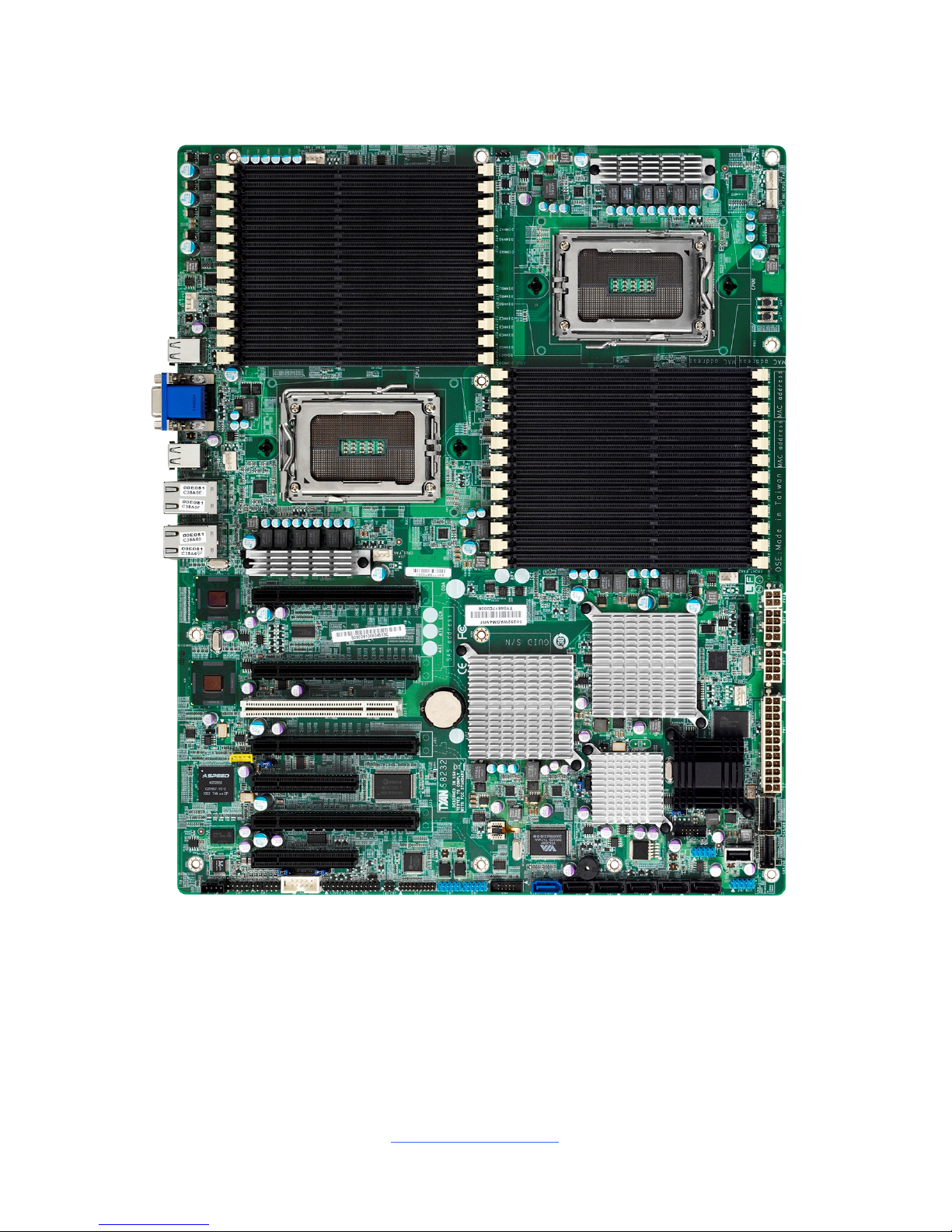
2.1 Board Image
This picture is representative of the latest board revision available at the time of
publishing. The board you receive may not look exactly like the above picture.
http://www.tyan.com
15
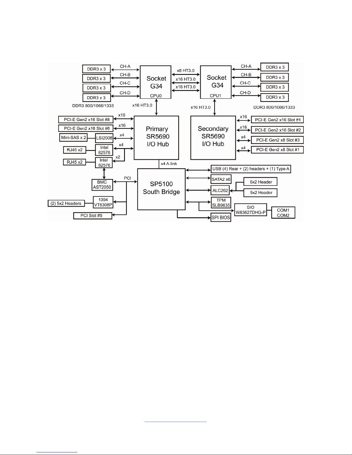
2.2 Block Diagram
S8232 Block Diagram
http://www.tyan.com
16
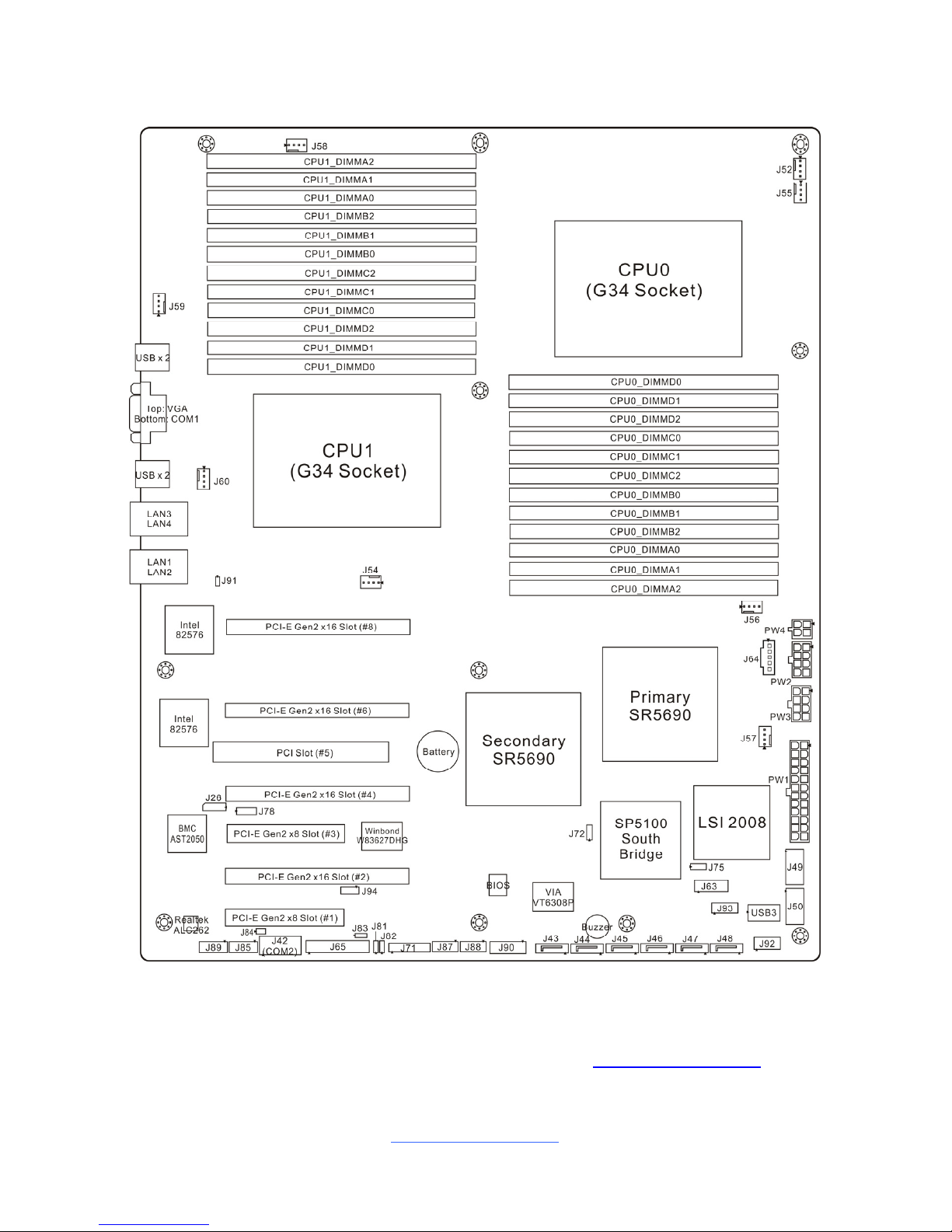
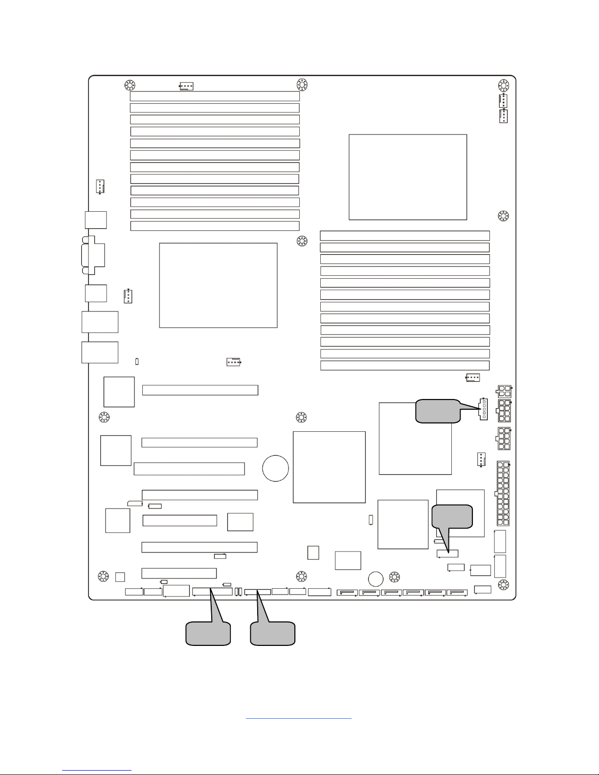
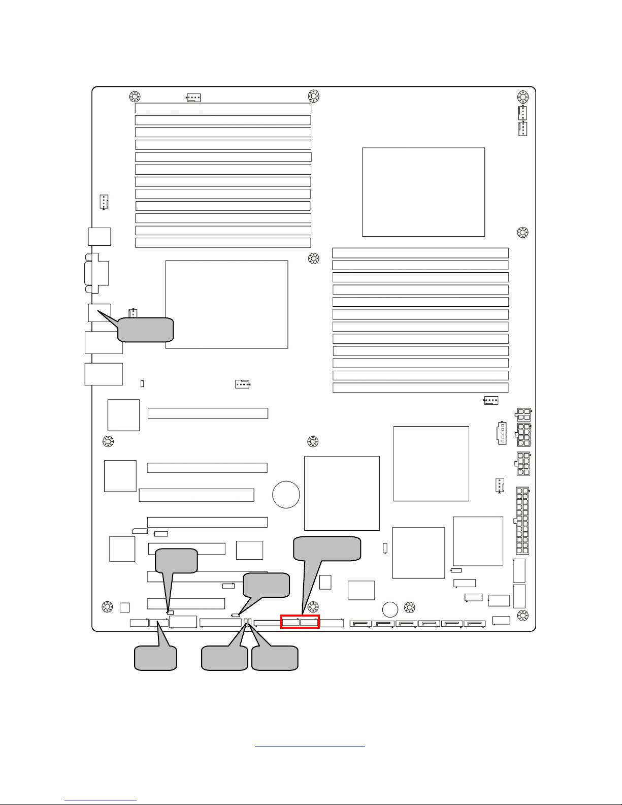
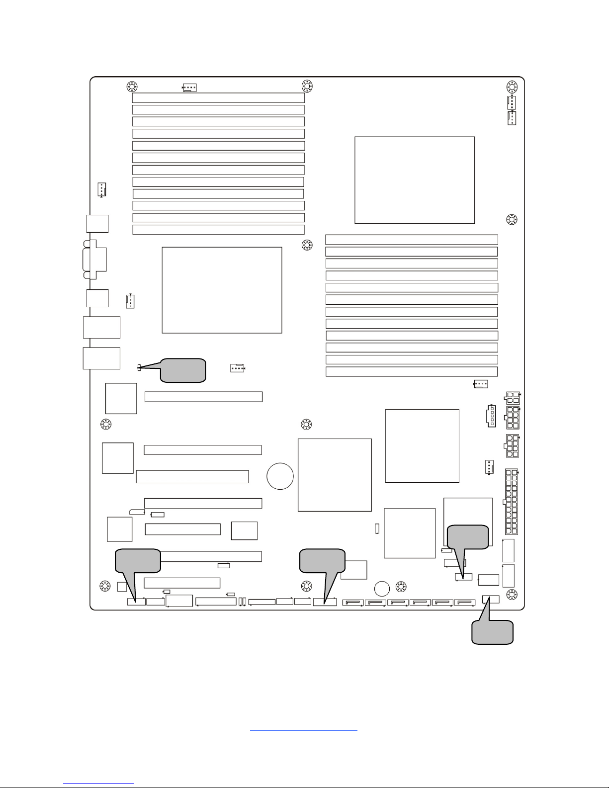
2.3 Board Parts, Jumpers and Connectors
This diagram is representative of the latest board revision available at the time of
publishing. The board you receive may not look exactly like the above diagram. But
for the DIMM number please refer to the above placement for memory installation.
For the latest board revision, please visit our web site at http://www.tyan.com
.
http://www.tyan.com
17
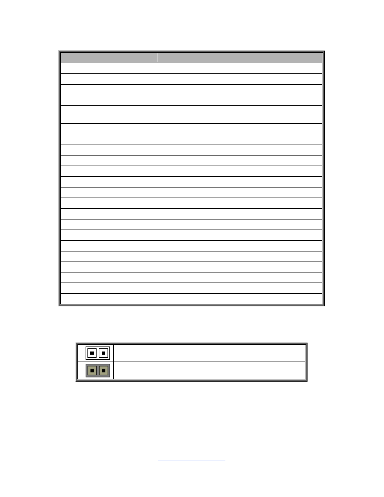
Jumpers & Connectors
Jumper/Connector Function
J26 IPMB Connector
J42 (COM2) COM2 Header
J43/J44/J45/J46/J47/J48 Serial ATA Connector Ports
J49/J50 Mini-SAS Connector Ports
J52/J54/J55/J56/
J57/J58/J59/J60
4-pin Fan Connectors
J63 SAS Fault LED Header
J64 PSMI Connector
J65 Front Panel Header
J71 2x10 pin Fan Connector (Barebones use only)
J72 Clear CMOS Jumper
J75 SAS Enable/Disable Jumper
J78 VGA Enable/Disable Jumper
J81/J82 LAN3/LAN4 FP LED Headers
J83 Chassis Intrusion Header
J84 ID LED Header
J85 FP Audio Header
J87/J88 IEEE 1394 Headers
J89 Audio Header
J90 SP5100 SGPIO Header
J91 Onboard ID LED Header
J92/J93 USB Front Panel Headers
USB3 Vertical (Type-A) USB Connector
Jumper Legend
OPEN - Jumper OFF
Without jumper cover
CLOSED - Jumper ON
With jumper cover
http://www.tyan.com
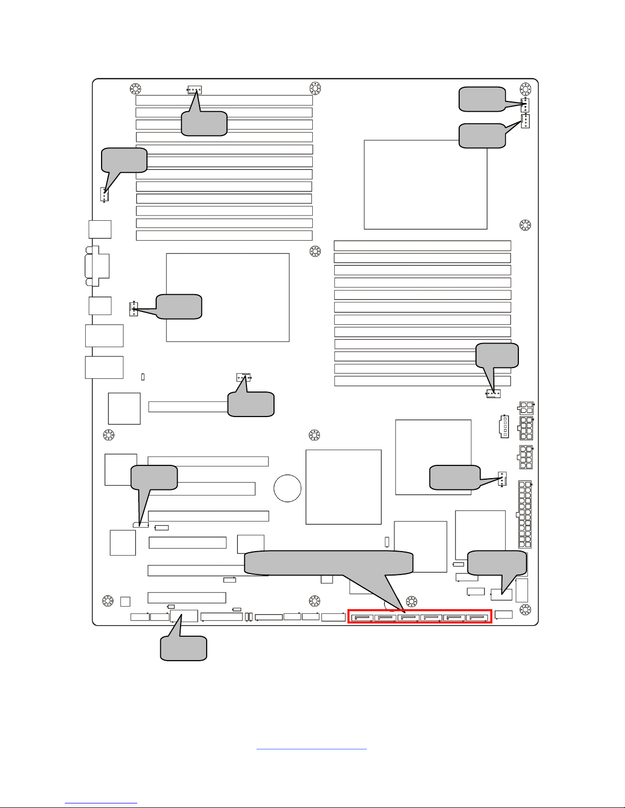
18
USB3J43/J44/J45/J46/J47/J48
J56
J52
J59
J57
J55
J58
J60
J54
J42
J26
http://www.tyan.com
19
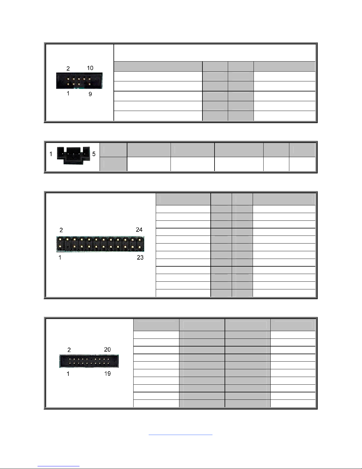
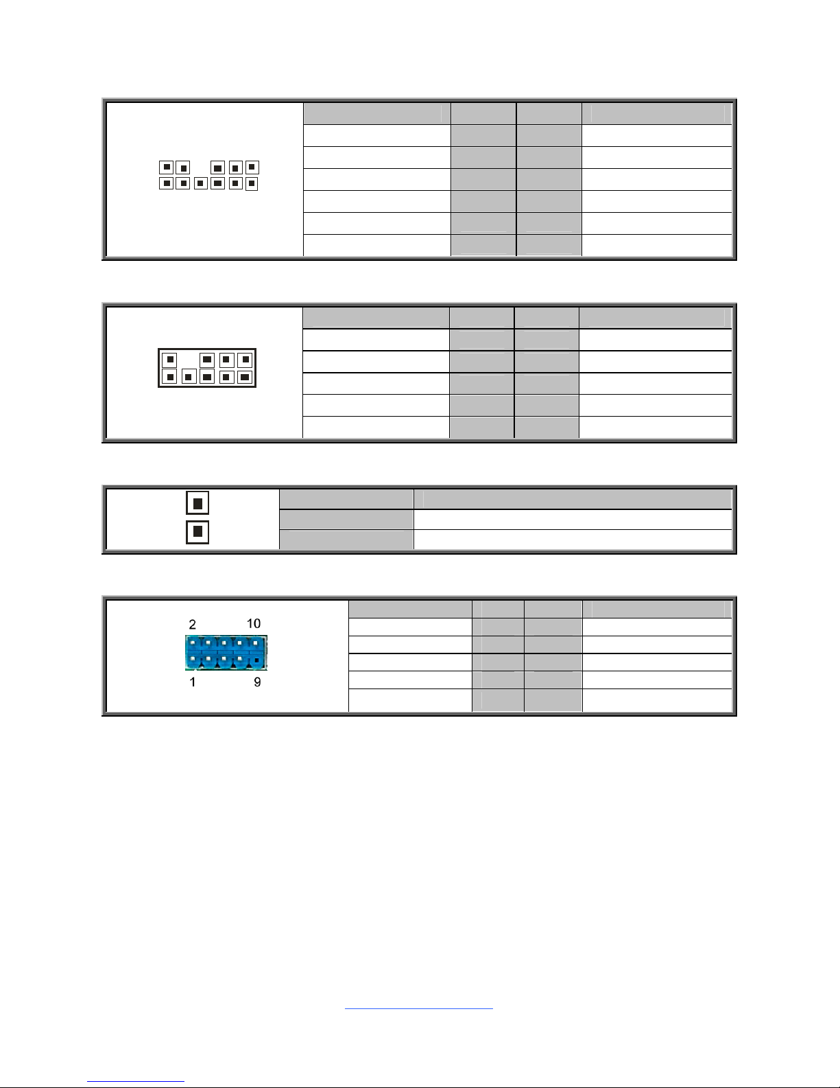
J26: IPMB Connector
Signal Pin Pin Signal
IPMB_SDA 1 2 GND
IPMB_SCLK 3 4 NC
J42: COM2 Connector
Signal Pin Pin Signal
DCD 1 2 DSR
RXD 3 4 RTS
TXD 5 6 CTS
DTR 7 8 RI
GND 9 10 KEY
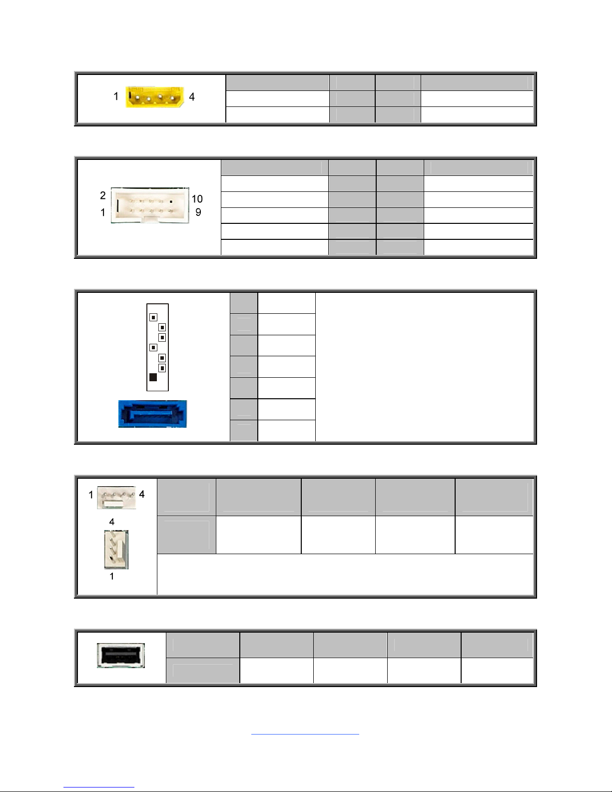
J43/J44/J45/J46/J47/J48/J49/J50: Serial ATA Connector
7 GND
6 RXP
5 RXN
4 GND
3 TXN
2 TXP
7
1
1 GND
Connects to the Serial ATA ready
drives via the Serial ATA cable.
J52/J54/J55/J56/J57/J58/J59/J60: 4-Pin FAN Connectors
Pin 1 2 3 4
Signal GND P12V TACH PWM
Use this header to connect the cooling fan to your motherboard to keep the
system stable and reliable.
USB3: Vertical (Type A) USB Connectors
Pin 1 2 3 4
Signal P5V DATA- DATA+ GND
http://www.tyan.com
20
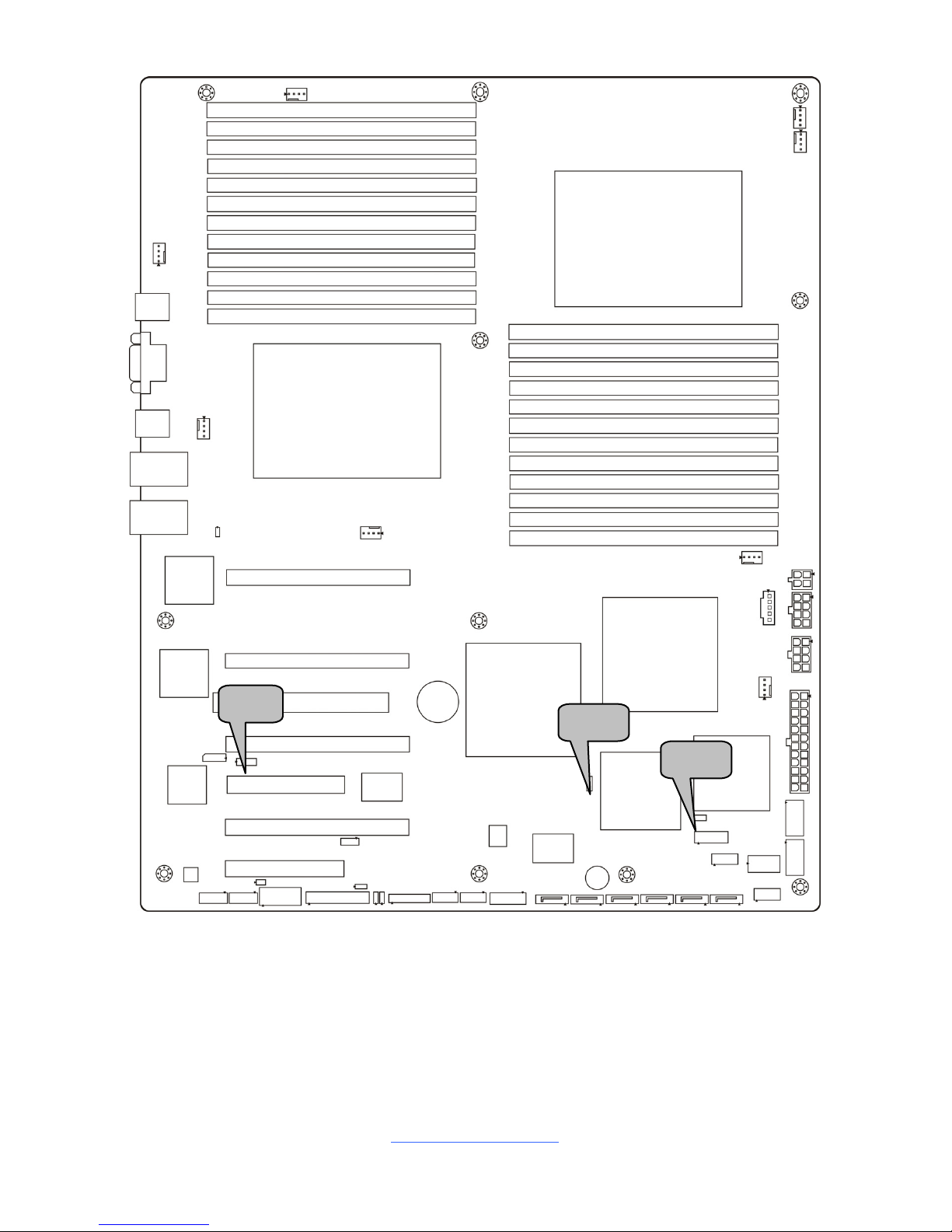
J64
J71J65
J63
http://www.tyan.com
21
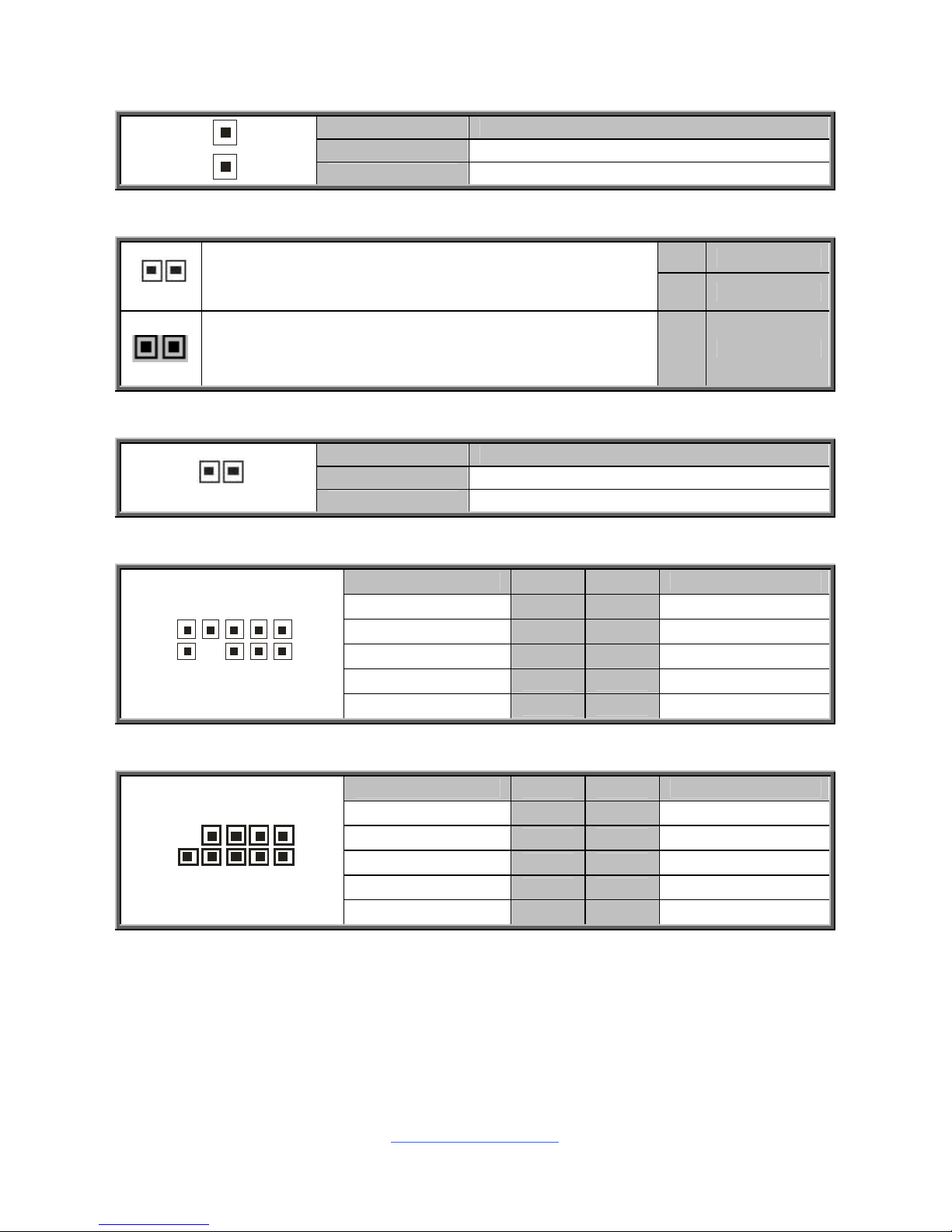
J63: SAS Fault LED Header
Use this header to connect to the CPLD firmware update tool
Signal Pin Pin Signal
LED0_L 1 2 LED1_L
LED2_L 3 4 LED3_L
LED4_L 5 6 LED5_L
KEY 7 8 LED7_L
LED6_L
9 10 GND
J64: PSMI Connector
Pin 1 2 3 4 5
Signal SMCLK SMDAT ALERT_L- GND VCC3
J65: Front Panel Header
Signal Pin Pin Signal
Power LED+ 1 2 PWR
KEY 3 4 System ID LED+
Power LED - 5 6 System ID LEDHD LED+ 7 8 Fault LED
HD LED - 9 10 PSU Fault LED
Power SW 11 12 LAN1 LED +
GND 13 14 LAN1 LED Reset SW 15 16 SMB Host Data
GND 17 18 SMB Host CLK
ID SW 19 20 INTRU#
TEMP Sensor 21 22 LAN3 LED +
NMI 23 24 LAN3 LED -
J71: 2x10-Pin FAN connector for TYAN (Barebones use only)
Signal Pin Pin Signal
TACH1 1 2 TACH6
TACH2 3 4 TACH7
TACH3 5 6 TACH8
TACH4 7 8 TACH9
TACH5 9 10 TACH10
GND 11 12 KEY
PWM4 13 14 PWM3
TACH11 15 16 N/A
TACH12 17 18 N/A
N/A 19 20 PWM5
http://www.tyan.com
22
LED1
J84
J81 J82
J83
J85
J87/J88
http://www.tyan.com
23
J81/J82: LAN3/LAN4 Front Panel LED Header
Pin Signal
1 LED+
1
2 LED-
J83: Chassis Intrusion Header
Pin Signal
1
Open: Use this jumper to disable the system
chassis intrusion alarm.
1 INTRUDER_L
Closed: Use this jumper to trigger the system
chassis intrusion alarm. (Default)
2 GND
J84: ID LED Header
Pin Signal
1 IDLEDBTN_N
1
2 GND
J85: FP Audio Header
Signal Pin Pin Signal
MIC_L 1 2 GND_AUDIO
MIC_R 3 4 FP_FRNT_L
LINE_IN_R 5 6 FP_IO_SNS
GND_AUDIO 7 8 KEY
1
0
9
2
1
LINE_IN_L 9 10 FP_IO_SNS
J87/J88: IEEE 1394 Header
Signal Pin Pin Signal
XTPA_P 1 2 XTPA_M
GND 3 4 GND
XTPB_P 5 6 XTPB_M
FWAPWR 7 8 FWAPWR
10
9
2
1
KEY 9 10 GND
http://www.tyan.com
24
J89
J91
J90
J92
J93
http://www.tyan.com
25
J89: Audio Header
Signal Pin Pin Signal
MIC_L 1 2 MIC_R
GND_AUDIO 3 4 MIC_JD
LINE_IN_R 5 6 LINE_IN_R
KEY 7 8 LINE_IN_JD
LINE_OUT_L 9 10 LINE_OUT_R
1
1
2112
N/A 11 12 FRONT_JD
J90: SP5100 SGPIO Header
Signal Pin Pin Signal
SB700_SCLK0 1 2 SP5100_SIO_DIN
SB700_SDAT0 3 4 SP5100_SIO_DOUT
GND 5 6 SP5100_SIO_END
KEY 7 8 SP5100_SIO_CLK
10
9
2
1
N/A 9 10 SATA_ERROR_LED
J91: Onboard ID LED Header
Pin Signal
1 ID LED+
1
2 ID LED-
J92/J93: USB Front Panel Connector
Signal Pin Pin Signal
P5V 1 2 P5V
DATA1- 3 4 DATA2DATA1+ 5 6 DATA2+
GND 7 8 GND
KEY 9 10 GND
http://www.tyan.com
26
J72
J75
J78

http://www.tyan.com
27
J72: Clear CMOS Jumper
3
1
Normal (Default)
3
1
Clear CMOS
You can reset CMOS by using this jumper if you have
forgotten your system/setup password or need to clear BIOS
setting.
1. Power off system and disconnect both power connectors
from the motherboard.
2. Use jumper cap to close Pin_2 and Pin_3 for seconds to
Clear CMOS.
3. Put jumper cap back to Pin_1 and Pin_2 (default setting).
4. Reconnect power & power on system.
J75: SAS Enable/Disable Jumper
3
1
Pin 1-2 Closed: Normal (Default)
1
3
Pin 2-3 Closed: Disable on-board SAS function
J78: VGA Enable/Disable Jumper
3
1
Pin 1-2 Closed: Normal (Default)
1
3
Pin 2-3 Closed: Disable Video from BMC AST2050
http://www.tyan.com
28
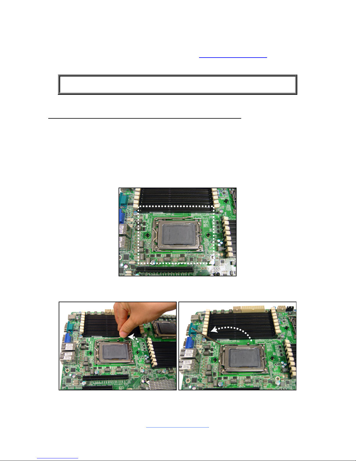
2.4 Installing the Processor and Heat sink
The S8232 supported AMD® processors are listed in section Hardware
Specifications on page 4. Check our website at http://www.tyan.com
for latest
processor support.
NOTE: MiTAC is not liable for damage as a result of operating an
unsupported configuration.
Processor Installation (G34 1944-pin Socket for AMD CPU)
Follow the steps below to install the processors and heat sinks. Please note that the
illustrations are based on a G34 1944-pin Socket which may not look exactly like
the motherboard you purchased. Therefore, the illustrations should be held for your
reference only.
NOTE: If only one processor is installed, start with CPU0 first.
1. Locate the CPU socket.
2. Pull the CPU lever slightly away from the socket and then push it to a fully
open position.

http://www.tyan.com
29
3. Lift the socket cover to a fully open position.
4. Take off the CPU protection cap.
5. Place the CPU in the CPU socket.
 Loading...