

TYAN S7106 User Manual

http://www.tyan.com
1
S7106
Version 1.0
Copyright
Copyright © 2017 MiTAC International Corporation. All rights reserved. No part of
this manual may be reproduced or translated without prior written consent from
MiTAC International Corporation.
Trademark
All registered and unregistered trademarks and company names contained in this
manual are property of their respective owners including, but not limited to the
following.
TYAN® is a trademark of MiTAC International Corporation.
Intel® is a trademark of Intel® Corporation.
AMI, AMI BIOS are trademarks of AMI Technologies.
Microsoft®, Windows® are trademarks of Microsoft Corporation.
Winbond® is a trademark of Winbond Electronics Corporation.
Notice
Information contained in this document is furnished by MiTAC International
Corporation and has been reviewed for accuracy and reliability prior to printing.
MiTAC assumes no liability whatsoever, and disclaims any express or implied
warranty, relating to sale and/or use of TYAN® products including liability or
warranties relating to fitness for a particular purpose or merchantability. MiTAC
retains the right to make changes to product descriptions and/or specifications at
any time, without notice. In no event will MiTAC be held liable for any direct or
indirect, incidental or consequential damage, loss of use, loss of data or other
malady resulting from errors or inaccuracies of information contained in this
document.

http://www.tyan.com
2
Contents
S7106 ....................................................................................................... 1
Before you begin… ................................................................................ 3
Chapter 1: Instruction ............................................................................. 4
1.1 Congratulations .............................................................................. 4
1.2 Hardware Specifications................................................................. 4
1.3 Software Specifications .................................................................. 9
Chapter 2: Board Installation ............................................................... 10
2.1 Board Image ................................................................................ 11
2.2 Block Diagram ............................................................................. 13
2.3 Motherboard Mechanical Drawing ................................................ 14
2.4 Board Parts, Jumpers and Connectors ......................................... 15
2.5 LED Definitions ............................................................................ 24
2.6 Installing the Processor and Heatsink ........................................... 25
2.7 Tips on Installing Motherboard in Chassis .................................... 28
2.8 Installing the Memory ................................................................... 30
2.9 Attaching Drive Cables ................................................................. 35
2.10 Installing Add-In Cards ............................................................... 36
2.11 Connecting External Devices ..................................................... 37
2.12 Installing the Power Supply ........................................................ 38
2.13 Finishing Up ............................................................................... 38
Chapter 3: BIOS Setup.......................................................................... 39
3.1 About the BIOS ............................................................................ 39
3.2 Main Menu ................................................................................... 41
3.3 Advanced Menu ........................................................................... 43
3.4 Platform Configuration Menu ........................................................ 71
3.5 Socket Configuration .................................................................... 85
3.6 Server Management....................................................................107
3.7 Security ......................................................................................112
3.8 Boot ............................................................................................117
3.9 Save & Exit .................................................................................120
Chapter 4: Diagnostics ........................................................................122
4.1 Flash Utility .................................................................................122
4.2 AMIBIOS Post Code (Aptio) ........................................................123
Appendix I: Fan and Temp Sensors ....................................................130
Glossary ...............................................................................................136
Technical Support................................................................................142
http://www.tyan.com
3
Before you begin…
Check the box contents!
The retail motherboard package should contain the following:
S7106 Motherboard x 1
SATA Single Cable x 2
Rear IO shielding x 3
CPU clip for
Narrow Non-Fabric
CPU Carrier x 2
1 x S7106 Quick Installation Guide
1 x TYAN® Driver CD
M.2 Screw kit x1
IMPORTANT NOTE:
Sales samples may not come with any of the accessories listed above.
If you have ordered a sales sample and you are missing any of the above items,
please contact your sales representative to help order accessories.

http://www.tyan.com
4
Chapter 1: Instruction
1.1 Congratulations
You have purchased the powerful TYAN® S7106 motherboard, based on the Intel®
C621/C622 Lewisburg chipset. The S7106 is designed to support Intel® Xeon®
Skylake Scalable Processor Families, and Up to 512GB RDIMM/ 1024GB
LRDIMM/ 768GB LRDIMM 3DS* DDR4 memory. Leveraging advanced technology
from Intel®, the S7106 is capable of offering scalable 32 and 64-bit computing, highbandwidth memory design, and lightning-fast PCI-E bus implementation.
The S7106 not only empowers you in today‟s demanding IT environment but also
offers a smooth path for future application upgradeability. All of these rich feature
sets provide the S7106 with the power and flexibility to meet demanding
requirements for today‟s IT environments.
Remember to visit the TYAN® website at http://www.tyan.com. There you can find
all the information on all TYAN® products as well as all the supporting documentation,
FAQs, Drivers and BIOS upgrades.
1.2 Hardware Specifications
S7106GM2NR
Processor
Socket Type / Q'ty
LGA3647/ (2)
Supported CPU
Series
Intel Xeon Skylake Scalable
Processor Families
Thermal Design
Power (TDP)
wattage
Max up to 205W
Chipset
PCH
S7106GM2NR Intel C621
Memory
Supported DIMM
Qty
(8)+(8) DIMM slots
DIMM Type /
Speed
DDR4 RDIMM/RDIMM
3DS/LRDIMM/LRDIMM 3DS 2666
Capacity
Up to 512GB RDIMM/ 1,024GB
LRDIMM/ 768GB LRDIMM 3DS
*Follow latest Intel DDR4 Memory
POR
Memory channel
6 Channels per CPU
Memory voltage
1.2V
http://www.tyan.com
5
Expansion Slots
PCI-E
(2) PCI-E Gen3 x24 slots
Others:
(2) PCI-E Gen3 x16 OCP 2.0 slots
(con.A+con.C or con.F+con.G)
(1) PCI-E Gen3 x2 for M.2 Port
(2242/2260/2280)
LAN
Port Q'ty
(2) GbE ports, (1) PHY dedicated
for IPMI
Controller
Intel I210-AT
PHY
Realtek RTL8211E
Storage
SATA
Connector
(2) Mini-SAS HD (8-ports)
Controller
Intel C621
Speed
6.0 Gb/s
RAID
RAID 0/1/10/5 (Intel
RSTe)
M.2
connector
(1) M.2 connector
(2242/2260/2280)
by PCI-E
interface
sSATA
Connector
(1) Mini-SAS HD (4-ports)
+ (2) SATA-III
Controller
Intel C621
Speed
6.0 Gb/s
RAID
RAID 0/1/10/5 (Intel
RSTe) only for 4 SATA
devices
Graphic
Connector type
D-Sub 15-pin
Resolution
Up to 1920x1200
Chipset
Aspeed AST2500
Input /Output
USB
(2) USB3.0 ports (via cable), (2)
USB3.0 ports (at rear), (2) USB 2.0
ports (via cable), (1) Type-A
USB3.0 port
COM
(2) ports (1 at rear, 1 via cable)
VGA
(2) D-Sub ports (1 at rear, 1 via
cable)
RJ-45
(2) GbE ports, (1) Dedicated for
IPMI
Front Panel
(1) 2x12-pin SSI front panel header
SATA
(2) SATA-III connectors + (3) Mini-

http://www.tyan.com
6
SAS HD (4-in-1) connectors
Power
(1) ATX 24-pin + (2) 8-pin power
connectors
Others
(1) UID button
TPM (Optional)
TPM Support
Please refer to our TPM supported
list.
System Monitoring
Chipset
Aspeed AST2500
Fan
Total (5) 4-pin headers
Temperature
Monitors temperature for CPU &
memory & system environment
Voltage
Monitors voltage for CPU, memory,
chipset & power supply
LED
Over temperature warning indicator,
Fan & PSU fail LED indicator
Others
Watchdog timer support
Server Management
AST2500 iKVM
Feature
IPMI 2.0 compliant baseboard
management controller (BMC),
Supports storage over IP and
remote platform-flash, USB 2.0
virtual hub
AST2500 IPMI
Feature
24-bit high quality video
compression, 10/100/1000 Mb/s
MAC interface
BIOS
Brand / ROM size
AMI, 32MB
Feature
PXE boot support, ACPI 5.0,
SMBIOS 3.0/PnP/Wake on LAN,
ACPI sleeping states S4,S5, Userconfigurable H/W monitoring
Physical Dimension
Form Factor
EATX
Board Dimension
12"x13" (305x330mm)
Regulation
FCC (DoC)
Class B
CE (DoC)
Yes
Operating Environment
Operating Temp.
10° C ~ 35° C (50° F~ 95° F)
Non-operating
Temp.
- 40° C ~ 70° C (-40° F ~ 158° F)
In/Non-operating
Humidity
90%, non-condensing at 35° C
RoHS
RoHS 6/6 Compliant
Yes
http://www.tyan.com
7
Operating System
OS supported list
Please refer to our Intel OS
supported list.
Package Contains
Motherboard
(1) S7106 Motherboard
Manual
(1) Web User's manual, (1) Quick
Installation Guide
Installation CD
(1) TYAN installation CD
S7106GM2NR-L2 Specifications
Processor
Socket Type / Q'ty
LGA3647/ (2)
Supported CPU
Series
Intel Xeon Skylake Scalable
Processor Families
Thermal Design
Power (TDP)
wattage
Max up to 205W
Chipset
PCH
Intel C622
Memory
Supported DIMM
Qty
(8)+(8) DIMM slots
DIMM Type /
Speed
DDR4 RDIMM/RDIMM
3DS/LRDIMM/LRDIMM 3DS 2666
Capacity
Up to 512GB RDIMM/ 1,024GB
LRDIMM/ 2,048GB LRDIMM 3DS
*Follow latest Intel DDR4 Memory
POR
Memory channel
6 Channels per CPU
Memory voltage
1.2V
Expansion Slots
PCI-E
(2) PCI-E Gen3 x24 slots
Others:
(2) PCI-E Gen3 x16 OCP 2.0 slots
(con.A+con.C or con.F+con.G)
(1) PCI-E Gen3 x2 for M.2 Port
(2242/2260/2280)
LAN
Port Q'ty
(2) GbE ports, (1) PHY dedicated for
IPMI
Controller
Intel I210-AT
PHY
Realtek RTL8211E
Storage
SATA
Connector
(2) Mini-SAS
HD (8-ports)
Controller
Intel C622
Speed
6.0 Gb/s
http://www.tyan.com
8
RAID
RAID 0/1/10/5
(Intel RSTe)
M.2
connector
(1) M.2 connector
(2242/2260/2280) by
PCI-E interface
sSATA
Connector
(2) SATA-III, (1)
Mini-SAS HD
(4-ports)
Controller
Intel C622
Speed
6.0 Gb/s
RAID
RAID 0/1/10/5
(Intel RSTe)
only for 4 SATA
devices
Graphic
Connector type
D-Sub 15-pin
Resolution
Up to 1920x1200
Chipset
Aspeed AST2500
Input /Output
USB
(2) USB3.0 ports ( via cable), (2)
USB3.0 ports (at rear), (2) USB 2.0
ports (via cable), (1) Type-A USB3.0
port
COM
(2) Ports (1 at rear, 1 via cable)
VGA
(2) D-Sub ports (1 at rear, 1 via
cable)
RJ-45
(2) GbE ports, (1) Dedicated for IPMI
Front Panel
(1) 2x12-pin SSI front panel header
SATA
(2) SATA-III connectors + (3) MiniSAS HD (4-in-1) connectors
Power
(1) ATX 24-pin + (2) 8-pin power
connectors
Others
(1) UID button
TPM (Optional)
TPM Support
Please refer to our TPM supported
list.
System Monitoring
Chipset
Aspeed AST2500
Fan
Total (5) 4-pin headers
Temperature
Monitors temperature for CPU &
memory & system environment
Voltage
Monitors voltage for CPU, memory,
chipset & power supply
http://www.tyan.com
9
LED
Over temperature warning indicator,
Fan & PSU fail LED indicator
Others
Watchdog timer support
Server Management
AST2500 iKVM
Feature
IPMI 2.0 compliant baseboard
management controller (BMC),
Supports storage over IP and
remote platform-flash, USB 2.0
virtual hub
AST2500 IPMI
Feature
24-bit high quality video
compression, 10/100/1000 Mb/s
MAC interface
BIOS
Brand / ROM size
AMI, 32MB
Feature
Hardware Monitor, SMBIOS
3.0/PnP/Wake on LAN, Boot from
USB device/PXE via LAN/Storage,
User Configurable FAN PWM Duty
Cycle, Console Redirection, ACPI
sleeping states S4,S5, ACPI 6.1
Physical Dimension
Form Factor
EATX
Board Dimension
12"x13" (305x330mm)
Regulation
FCC (DoC)
Class B
CE (DoC)
Yes
Operating Environment
Operating Temp.
10° C ~ 35° C (50° F~ 95° F)
Non-operating
Temp.
- 40° C ~ 70° C (-40° F ~ 158° F)
In/Non-operating
Humidity
90%, non-condensing at 35° C
RoHS
RoHS 6/6 Compliant
Yes
Operating System
OS supported list
Please refer to our AVL support
lists.
Package Contains
Motherboard
(1) S7106 Motherboard
Manual
(1) Web User's manual, (1) Quick
Installation Guide
Installation CD
(1) TYAN installation CD
1.3 Software Specifications
For the latest AST2500 User‟s Guide and OS (operation system) support, please
visit the Tyan‟s Web site at http://www.tyan.com for the latest information
http://www.tyan.com
10
Chapter 2: Board Installation
You are now ready to install your motherboard.
How to install our products right… the first time
The first thing you should do is read this user‟s manual. It contains important
information that will make configuration and setup much easier. Here are some
precautions you should take when installing your motherboard:
(1) Ground yourself properly before removing your motherboard from the
antistatic bag. Unplug the power from your computer power supply and
then touch a safely grounded object to release static charge (i.e. power
supply case). For the safest conditions, MiTAC recommends wearing a
static safety wrist strap.
(2) Hold the motherboard by its edges and do not touch the bottom of the
board, or flex the board in any way.
(3) Avoid touching the motherboard components, IC chips, connectors,
memory modules, and leads.
(4) Place the motherboard on a grounded antistatic surface or on the antistatic
bag that the board was shipped in.
(5) Inspect the board for damage.
The following pages include details on how to install your motherboard into your
chassis, as well as installing the processor, memory, disk drives and cables.
Caution!
1. To avoid damaging the motherboard and associated
components, do not use torque force greater than
7kgf/cm (6.09 lb/in) on each mounting screw for
motherboard installation.
2. Do not apply power to the board if it has been
damaged.
http://www.tyan.com
11
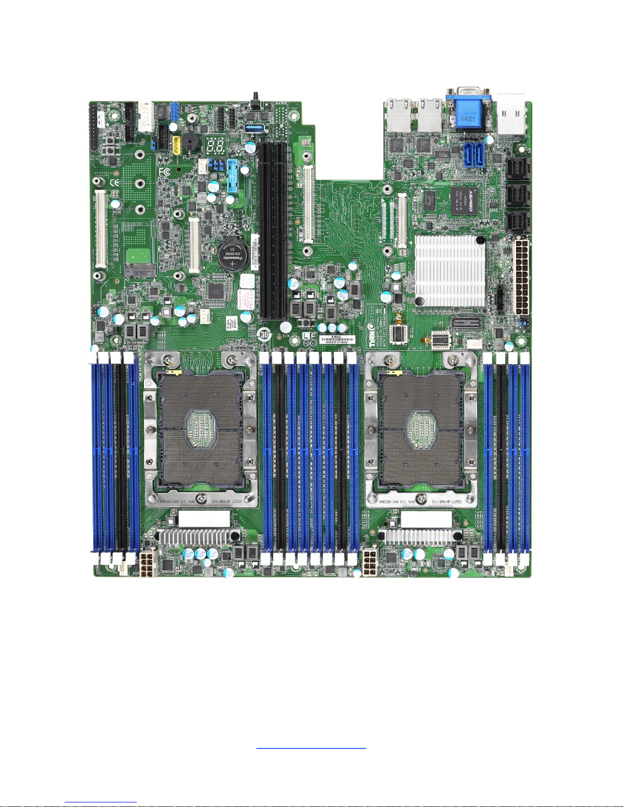
2.1 Board Image
S7106GM2NR
http://www.tyan.com
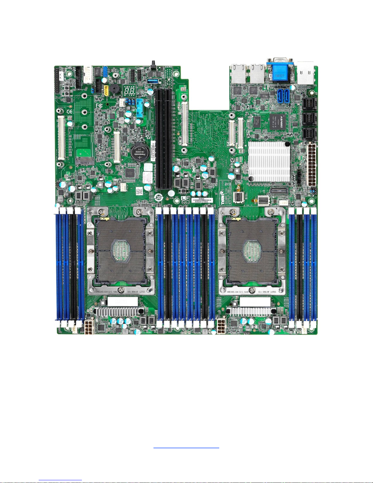
12
S7106GM2NR-L2
This picture is representative of the latest board revision available at the time of
publishing. The board you receive may not look exactly like the above picture.
http://www.tyan.com
13
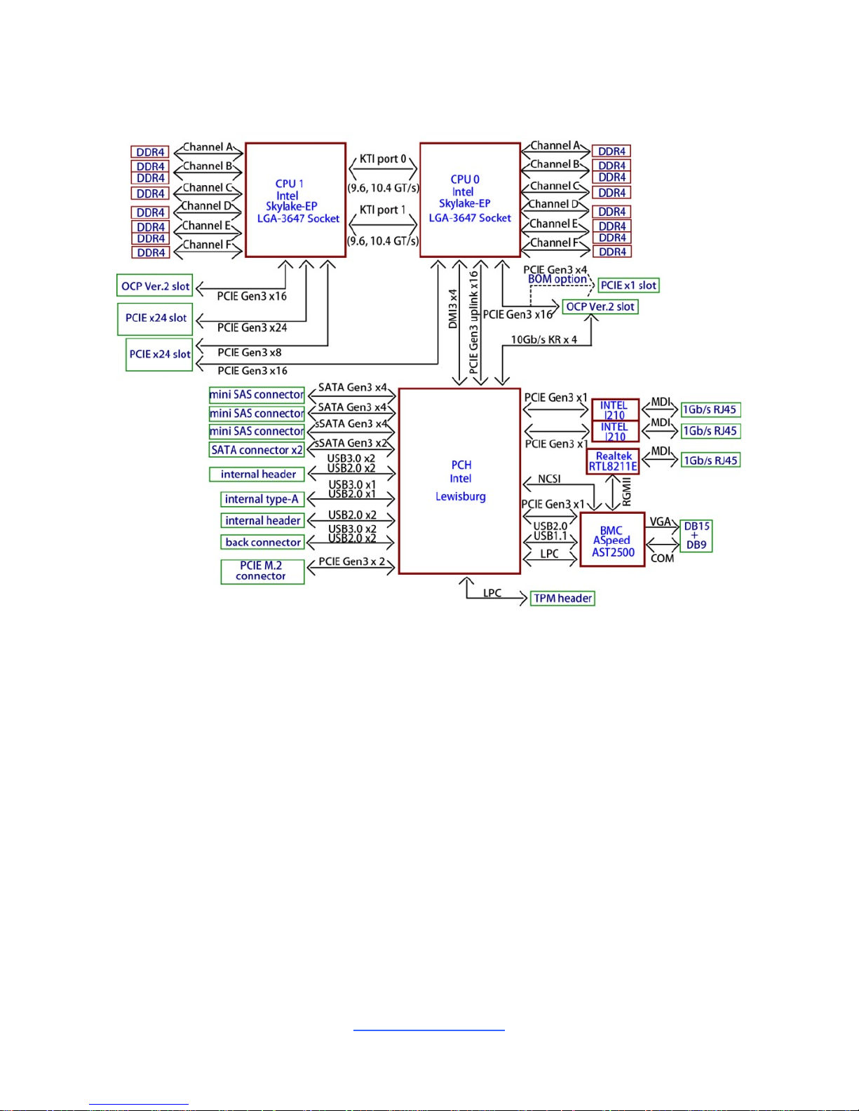
2.2 Block Diagram
S7106 Block Diagram
http://www.tyan.com
14
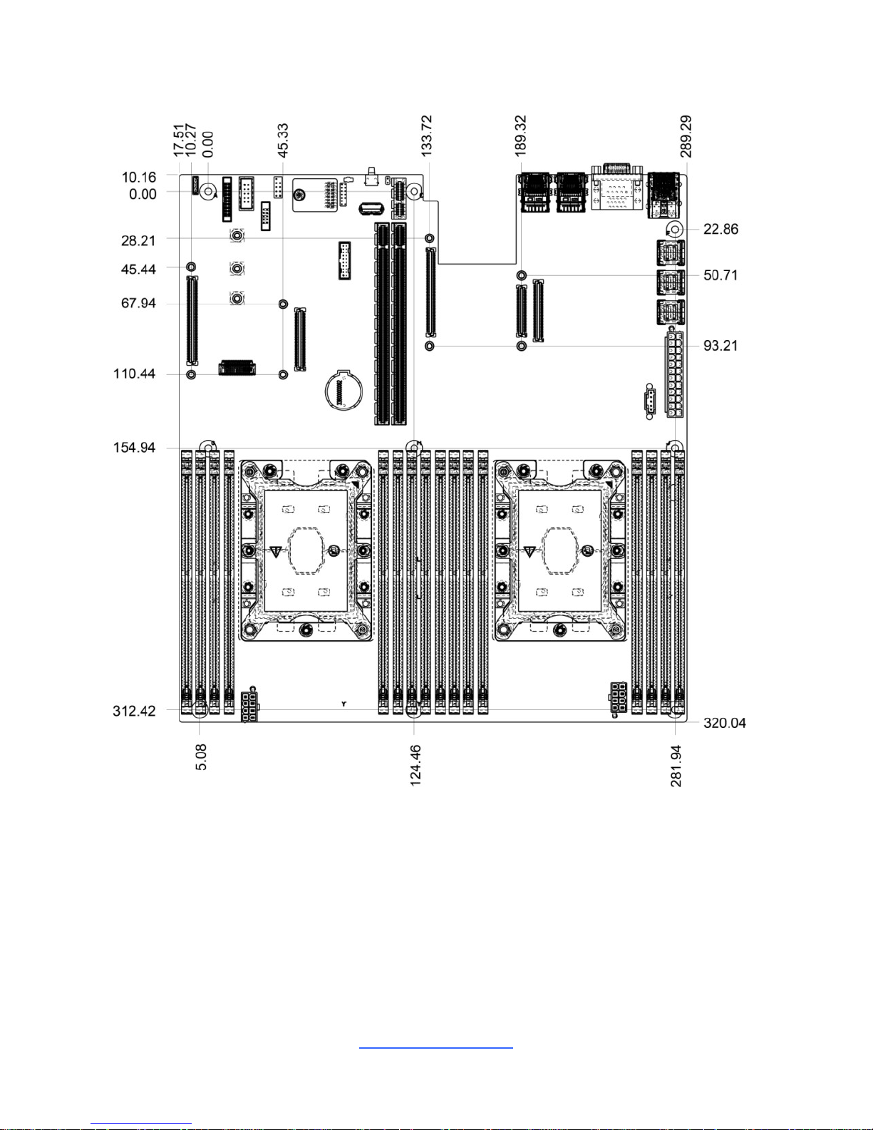
2.3 Motherboard Mechanical Drawing
http://www.tyan.com
15
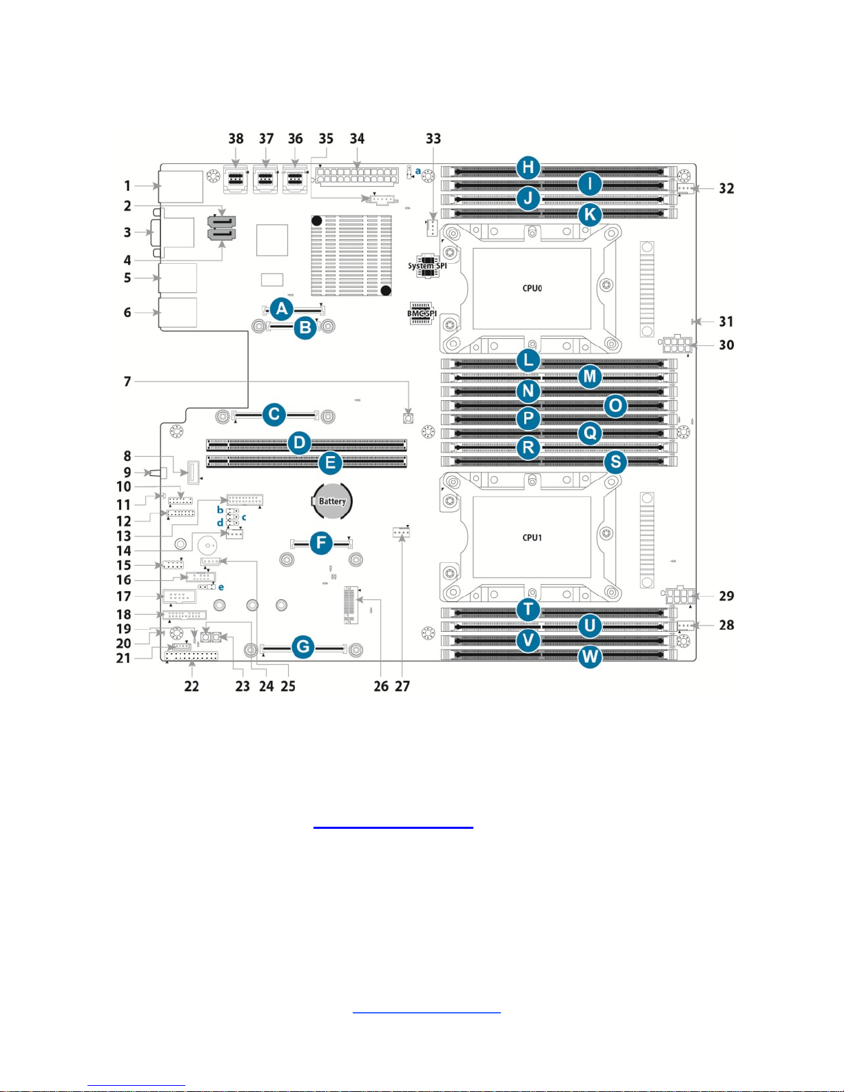
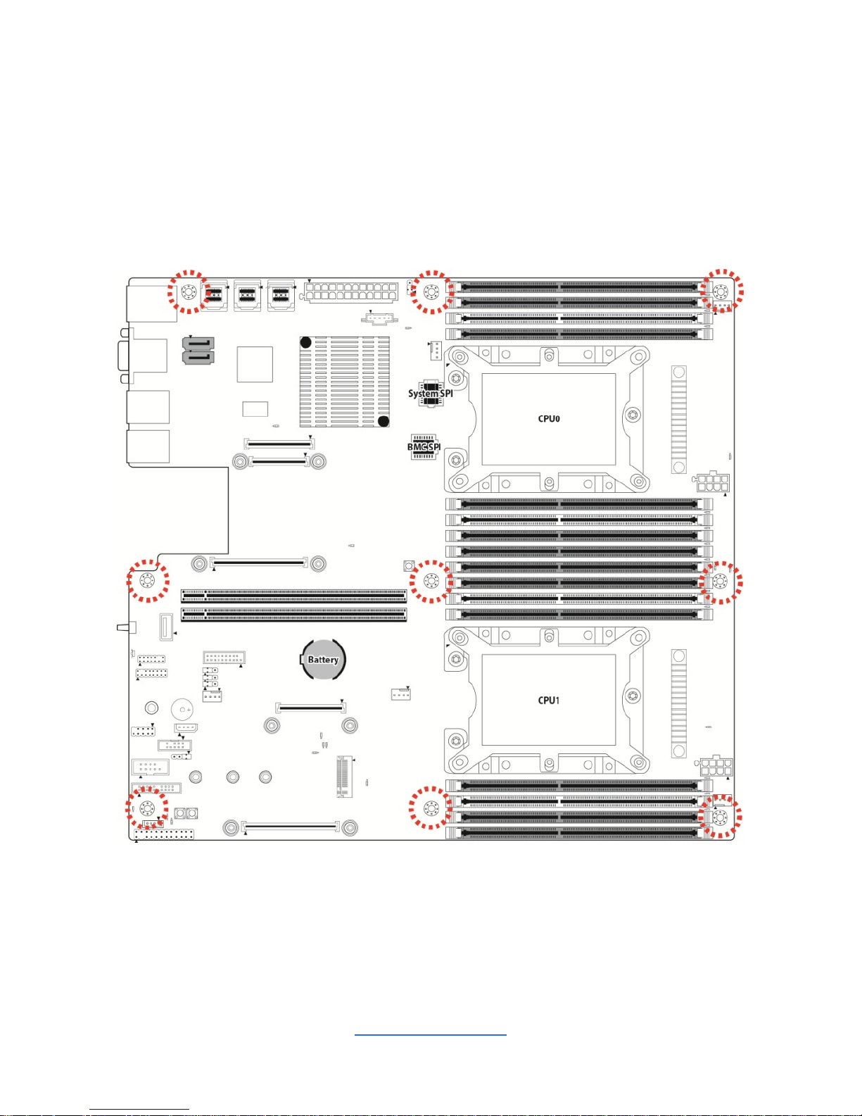
2.4 Board Parts, Jumpers and Connectors
This diagram is representative of the latest board revision available at the time of
publishing. The board you receive may not look exactly like the above diagram. The
DIMM slot numbers shown above can be used as a reference when reviewing the
DIMM population guidelines shown later in the manual. For the latest board revision,
please visit our web site at http://www.tyan.com.
http://www.tyan.com
16
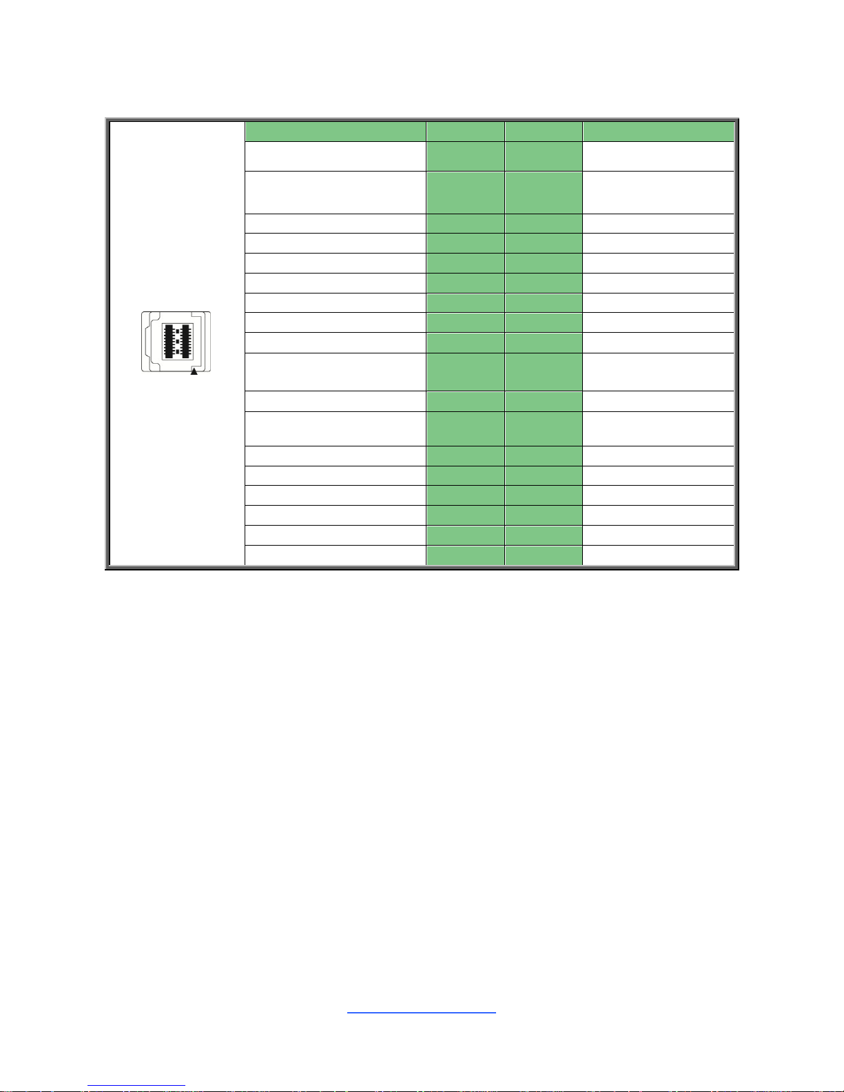
Motherboard Components
Connectors
1. Dedicated IPMI port+ USB3.0x2 (J112)
20. BMC Heartbeat LED (BMC_LED4)
2. SSATA Connector 4 (SSATA4)
21. PCH_SATA_RAID_KEY (J51)
3. VGA+COM Connector (VGA_COM1)
22. Front Panel Header (FPIO_1)
4. SSATA Connector 5 (SSATA5)
23. Reset Button (RST_ BTN1)
5. LAN Connector (LAN2)
24. Power Button (PWR_BTN1)
6. LAN Connector (LAN1)
25.IPMB Pin Header (IPMB_HD1)
7. Clear CMOS Button (CLEAR_BTN1)
26. M.2 NGFF PCIe 22x42/60/80mm Socket
(U58)
8. Vertical Type A USB Connector
(TYPEA_USB3)
27. CPU1 FAN Header (CPU1_FAN)
9. Rear ID LED Button(ID LED_BTN1)
28. SYS_FAN2 Header( SYS_FAN_2)
10. VGA Header (FPIO_VGA3)
29. SSI 8-pin CPU1 Power Connector (PW2)
11. Rear ID LED (ID_LED1)
30. SSI 8-pin CPU0 Power Connector (PW1)
12. TYAN Module Header (DBG_HD1)
31. CPU0 PVCCP POWER OK LED
(P0_PG_LED1)
13. Front Panel USB3.0 Header (USB3_FPIO1)
32. SYS_FAN 1 Header (SYS_FAN_1)
14. Rear IO_FAN 2 (SYS_FAN_3)
33. CPU0 FAN Header (CPU0_FAN)
15. Internal USB2.0 Header (J26)
34. ATX Power Connector (24 pin) (PWR1)
16. sSATA SGPIO Header for SSATA4/SSATA5
(SSATA_SGPIO1)
35. PSMI Pin Header (PSMI_HD1)
17. COM2 Header (HD_COM2)
36. 36-pin Vertical Mini SAS HD Connector
(SATA 3.0 signals)(PCH_SSATA_0123)
18. FAN Tachometer Header (FAN_HD1)
37. 36-pin Vertical Mini SAS HD Connector
(SATA 3.0 signals)(PCH_SATA_0123)
19. On board BMC IPMI ALERT LED
(IPMI_LED1)
38. 36-pin Vertical Mini SAS HD Connector
(SATA 3.0 signals) (PCH_SATA_4567)
Headers/Jumpers
a. ME Recovery Mode Jumper (J113)
d. PSU Throttling Jumper (J125)
b. BMC COM PORT Jumper (J119)
e. PC BEEP Jumper (J120)
c. BMC COM PORT Jumper (J118)
PCIE Slots
A+C. OCP 2.0 PCI-E Gen3x16 MEZZ slot
f/CPU0 for LAN Card
F+G. OCP 2.0 PCI-E Gen3x16 MEZZ slot
f/CPU1 for LAN card
Standalone C. OCP 1.0 PCI-E Gen3x8 MEZZ
slot f/CPU0 for LAN Card
StandaloneG.OCP 1.0 PCI-E Gen3x8 MEZZ slot
f/CPU1 for LAN card
B. OCP 2.0 KR interface(only available in
S7106GM2NR-L2 SKU)
D PCI-E Gen3x24 slot(x24 link) f/ CPU1
E. PCI-E Gen3x24 slot(x24 link) f/ CPU0
Memory Slots
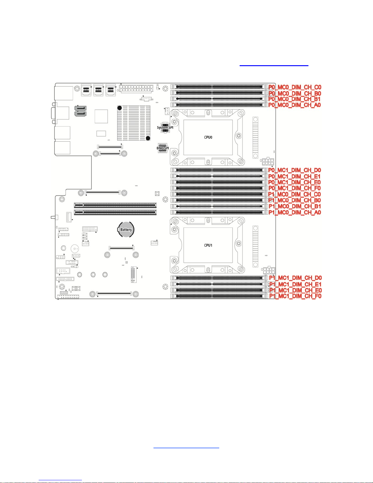
H. CPU0 Memory Slot (P0_MC0_DIM_CH_C0)
P CPU1 Memory Slot (P1_MC0_DIM_CH_C0)
I. CPU0 Memory Slot (P0_MC0_DIM_CH_B0)
Q CPU1 Memory Slot (P1_MC0_DIM_CH_B0)

http://www.tyan.com
17
J CPU0 Memory Slot (P0_MC0_DIM_CH_B1)
R CPU1 Memory Slot (P1_MC0_DIM_CH_B1)
K CPU0 Memory Slot (P0_MC0_DIM_CH_A0)
S CPU1 Memory Slot (P1_MC0_DIM_CH_A0)
L CPU0 Memory Slot (P0_MC1_DIM_CH_D0)
T CPU1 Memory Slot (P1_MC1_DIM_CH_D0)
M CPU0 Memory Slot (P0_MC1_DIM_CH_E1)
U CPU1 Memory Slot (P1_MC1_DIM_CH_E1)
N CPU0 Memory Slot (P0_MC1_DIM_CH_E0)
V CPU1 Memory Slot (P1_MC1_DIM_CH_E0)
O CPU0 Memory Slot (P0_MC1_DIM_CH_F0)
W CPU1 Memory Slot (P1_MC1_DIM_CH_F0)
http://www.tyan.com
18
SSATA4/SSATA5: sSerial Advanced Technology Attachment Gen3(sSATA)
7
1
Name
TYPE
S1
GND
S2
SATA TX DP
S3
SATA TX DN
S4
GND
S5
SATA RX DN
S6
SATA RX DP
S7
GND
Connects to the Serial ATA ready drives via the Serial ATA
cable.
TYPEA_USB3: Vertical (Type_A) USB3.0 Connector
Signal
Pin
Pin
Signal
+5V
1 2 USB2.0_DATA_N
USB2.0_DATA_P
3 4 GND
USB3.0_RX_N
5 6 USB3.0_RX_P
GND
7 8 USB3.0_TX_N
USB3.0_TX_P
9
ID LED_BTN1: Rear IO IDLED Button
Signal
Pin
Pin
Signal
FP_IDLED_BTN_N
1 2 GND
FPIO_VGA3: VGA Header
Signal
Pin
Pin
Signal
GND
1 2 VGA2_5V
GND
3 4 HD_VGA_R
GND
5 6 HD_VGA_G
GND
7 8 HD_VGA_B
GND
9
10
HD_VGA_DAT
VGA_HD_HS
11
12
KEY
VGA_HD_CLK
13
14
HD_VGA_VS
http://www.tyan.com
19
DBG_HD1: TYAN Module Header
Signal
Pin
Pin
Signal
P3V3
1 2 FRAME_N
LAD0
3 4 KEY
LAD1
5 6 PLT_RST_N
LAD2
7 8 GND
LAD3
9
10
CLK_33M
DBG_SERIRQ
11
12
GND
DBG_PRES_N
13
14
VCC3_AUX
TPM_ADDR_MB
15
16
PCH_TPM_PP_EN
USB3_FPIO1: Front USB3.0 Header
Signal
Pin
Pin
Signal
+5V
1 2 P0_RX_N
P0_RX_P
3 4 GND
P0_TX_N
5 6 P0_TX_P
GND
7 8 P0_N
P0_P
9
10
OC_N
P1_P
11
12
P1_N
GND
13
14
P1_TX_P
P1_TX_N
15
16
GND
P1_RX_P
17
18
P1_RX_N
+5V
19
20
Key
J26: Internal USB2.0 Header
Signal
Pin
Pin
Signal
+5V
1 2 +5V
USB DATA1-
3 4 USB DATA2-
USBDATA1+
5 6 USB DATA2+
GND
7 8 GND
KEY
9
10
GND
SSATA_SGPIO1: SSATA SGPIO Header for SSATA4/SSATA5
Signal
Pin
Pin
Signal
SMBCLK
1
2
SDATA IN
SMBDATA
3
4
SDATA OUT
GND
5 6 SLOAD
KEY
7 8 SCLOCK
VCC3_AUX
9
10
HD_ERROR_LED
http://www.tyan.com
20
HD_COM2: COM Port Header
Signal
Pin
Pin
Signal
COM_DCD
1 2 COM_DSR
COM_RXD
3 4 COM_RTS
COM_TXD
5 6 COM_CTS
COM_DTR
7 8 COM_NRI
GND
9
10
KEY
FAN_HD1: FAN Tachometer Header Header
Signal
Pin
Pin
Signal
TACH1
1 2 TACH6
TACH2
3 4 TACH7
TACH3
5 6 TACH8
TACH4
7 8 TACH9
TACH5
9
10
TACH10
GND
11
12
KEY
PWM2
13
14
PWM1
TACH11
15
16
SMB_DATA
TACH12
17
18
SMB_CLK
NC
19
20
PWM3
J51: PCH_SATA_RAID_KEY (HW Key for Intel VROC – NVMe only)
Pin
1
2
Signal
LAN1_LED1_FP+
LAN1_LINK_ACT#
FPIO1: Front Panel Connector
Signal
Pin
Pin
Signal
FP_PW_LED_PW
1 2 FP_PWER (VCC3_Aux)
KEY
3 4 FP_ID_LED_PW
FP_PW_LED_GND
5 6 FP_ID_LED_N
HDD_LED_PW
7 8 BMC_HW_FAULT_N
HDD_ACT_LED_N
9
10
BMC_SYS_FAULT_N
FP_PWR_BTN_N
11
12
LAN0_LED_P
GND
13
14
LAN0_LED_N
FP_RST_BTN_JP_N
15
16
FP_SMB_DAT
GND
17
18
FP_SMB_CLK
FP_IDLED_BTN_N
19
20
FP_INTRUSION_N
SYS_Air_Inlet
21
22
LAN1_LED_P
FP_NMI_BTN_N
23
24
LAN1_LED_N

http://www.tyan.com
21
IPMB_HD1: IPMB Connector
Signal
Pin
Pin
Signal
IPMB_DAT
1 2 GND
IPMB_CLK
3 4 VCC3_AUX
PSMI_HD1: PSMI Connector
Pin 1 2
3
4
5
Signal
SMB_CLK
SMB_DAT
SMB_ALERT#
GND
V3P3
CPU0/1 FAN/ SYS FAN1~3: 4-pin CPU Fan Connector
Pin 1 2 3 4
Signal
GND
VCC12
FAN_TACH
PWM
Use this header to connect the cooling fan to your motherboard to
keep the system stable and reliable.
Note: A 4-pin fan is required for fan support 4pin Control
Clear_BTN1: RTC reset Button for clear CMOS
Pin 1 2 3 4
Signal
GND
GND
RST_N
RST_N
PWR_BTN1: POWER Button
Pin 1 2 3 4
Signal
GND
GND
PWR_BTN1
PWR_BTN1
RST_BTN1: Reset Button
Pin 1 2 3 4
Signal
GND
GND
FP_RST_BTN_N
FP_RST_BTN_N
http://www.tyan.com
22
J113: ME Recovery Mode Jumper
Pin
1 2 3
Signal
NC
FM_ME_RCVR_N
1K-Pull down
Pin 1-2 Closed: Normal Mode (Default)
Pin 2-3 Closed: ME In Force Update Mode
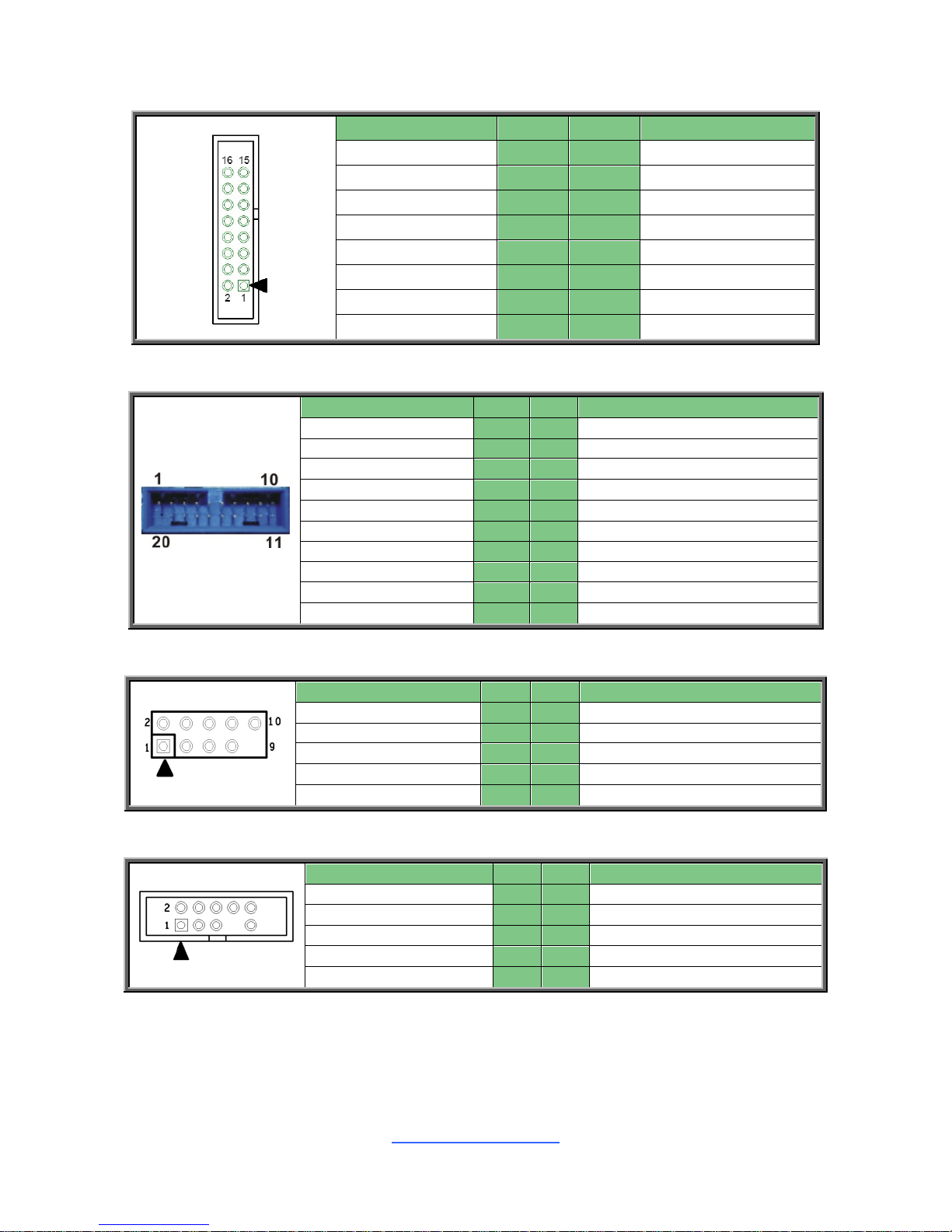
J120: BUZZER Disable Jumper
Pin
1 2 3
4
Signal
VCC5
NA
BUZ_1
BUZ_2
Pin 3-4 Closed: Normal Mode (Default)
Pin 2-3 Closed: Disable PC Beep
Pin 1-4 Closed: Use the External Speaker
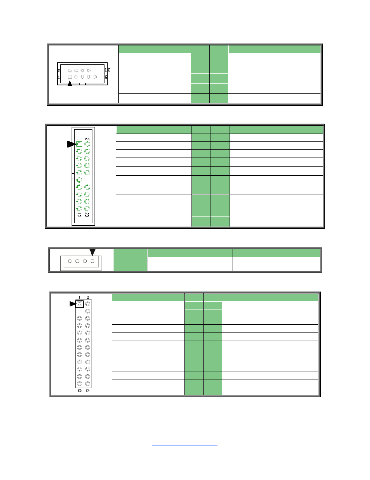
J118: BMC COM Port debug Jumper
Signal
Pin
Pin
Signal
BMC_COM2_RXD
1
2
RXD_2
BMC_COM5_RXD
3
1-2: BMC COM Port2(Default)
2-3: BMC COMSOLE Port5
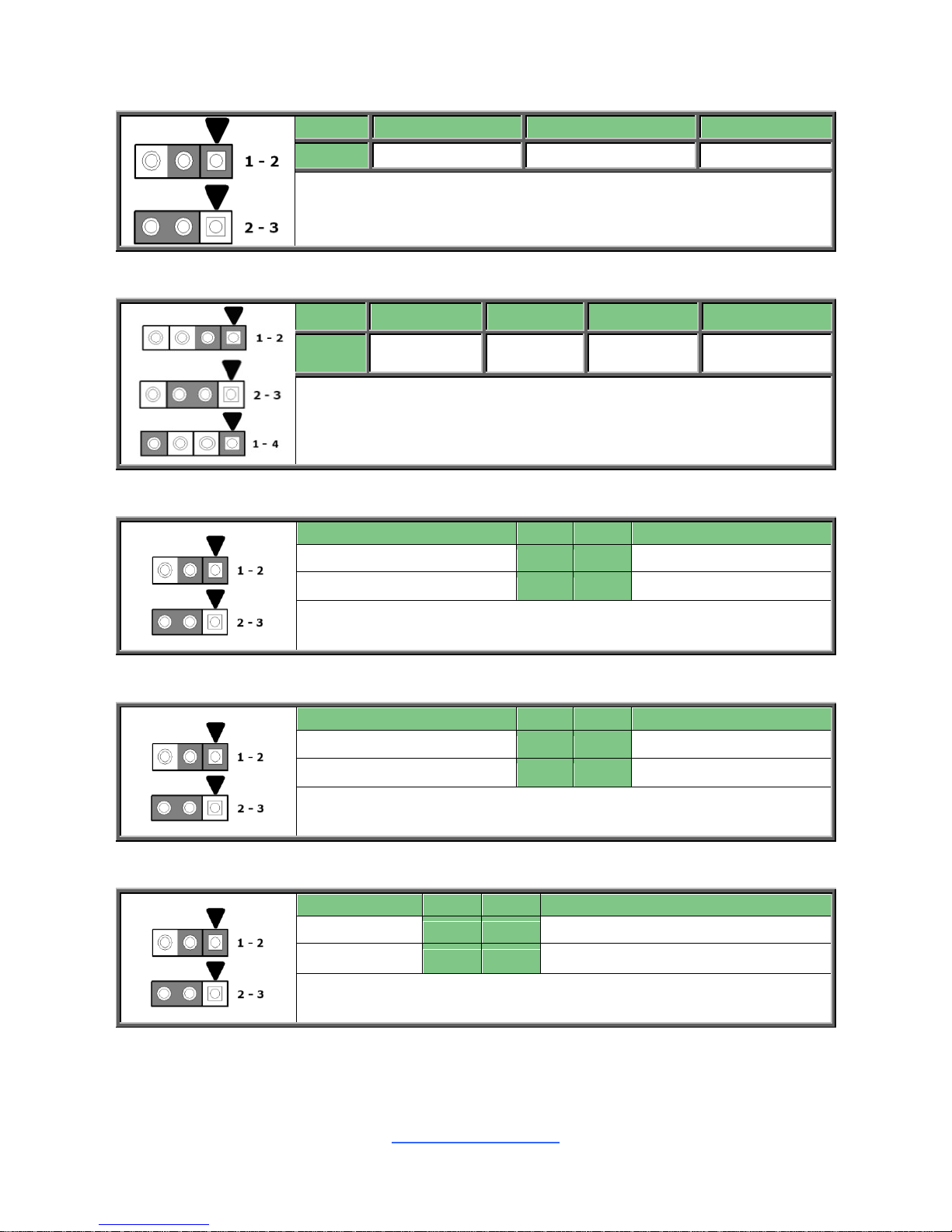
J119: BMC COM Port debug Jumper
Signal
Pin
Pin
Signal
BMC_COM2_TXD
1
2
TXD_2
BMC_COM5_TXD
3
1-2: BMC COM Port2(Default)
2-3: BMC COMSOLE Port5
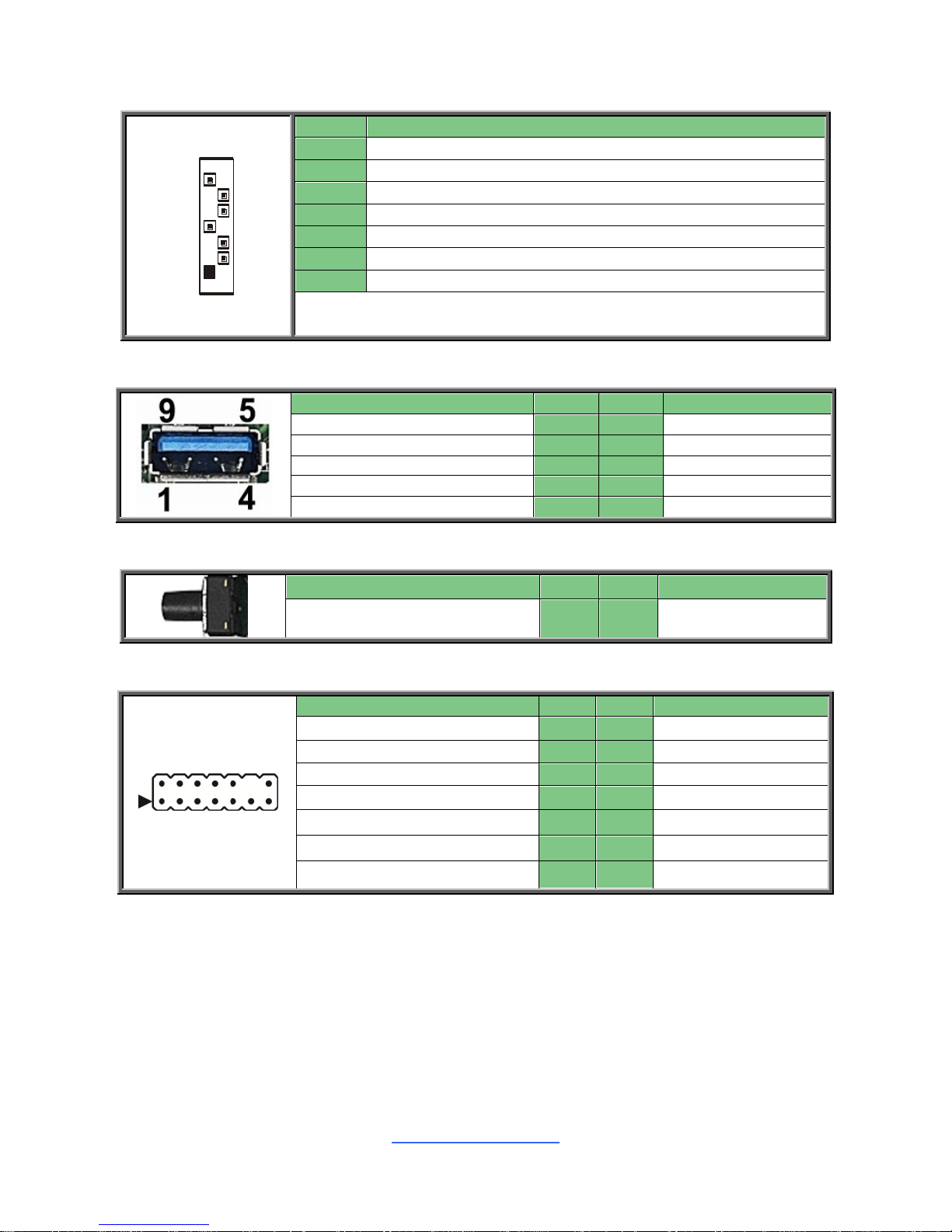
J125: PSU Throttling Jumper
Signal
Pin
Pin
Signal
NC
1
2
PSU_SMB_ALERT_BUFF_N_R
VCC3_Aux
3
1-2: Normal Mode(Default)
2-3: Enable PSU Throttling Function
http://www.tyan.com
23
Mini SAS HD Connector: (PCH_SATA_0123/ PCH_SATA_4567/
PCH_SSATA_0123)
Signal
Pin
Pin
Signal
SM_DAT
PIN A1
PIN A2
SGPIO _CLK
GND
PIN A3
PIN A4
SATA6G_RX_P1
SATA6G_RX_N1
PIN A5
PIN A6
GND
SATA6G_RX_P3
PIN A7
PIN A8
SATA6G_RX_N3
GND
PIN A9
PIN B1
GND
SGPIO _LOAD
PIN B2
PIN B3
GND
SATA6G_RX_P0
PIN B4
PIN B5
SATA6G_RX_N0
GND
PIN B6
PIN B7
SATA6G_RX_P2
SATA6G_RX_N2
PIN B8
PIN B9
GND
SGPIO_SATA_DATA
OUT0
PIN C1
PIN C2
GND
GND
PIN C3
PIN C4
SATA6G_TX_P1
SATA6G_TX_N1
PIN C5
PIN C6
GND
SATA6G_TX_P3
PIN C7
PIN C8
SATA6G_TX_N3
GND
PIN C9
PIN D1
NA
SM_CLK
PIN D2
PIN D3
GND
SATA6G_TX_P0
PIN D4
PIN D5
SATA6G_TX_N0
GND
PIN D6
PIN D7
SATA6G_TX_P2
SATA6G_TX_N2
PIN D8
PIN D9
GND
http://www.tyan.com
24
2.5 LED Definitions
BMC_LED4
BMC
Heart
Beat LED
Pin
Signal
+
+VCC3_SB
-
GND
State
Description
OFF
OFF
The LED shuts off when the
BMC controller cannot be
detected or properly initiated.
Blinking
Green
The LED blinks per second to
indicate that the BMC controller
is working normally
P0_PG_LED1
CPU1
PWOK
LED
Pin
Signal
+
+ VCC3
-
GND
State
Description
OFF
OFF
The LED shuts off when the
power of CPU1 is abnormal.
ON
Green
The LED lights up when the
power of CPU1 is normally.
P1_PG_LED1
CPU1
PWOK
LED
Pin
Signal
+
+ VCC3
-
GND
State
Description
OFF
OFF
The LED shuts off when the
power of CPU1 is abnormal.
ON
Green
The LED lights up when the
power of CPU1 is normally.
ID_LED1
Rear ID
LED
Pin
Signal
+
+ VCC3_AUX
-
GND
State
Description
OFF
OFF
OFF
ON
Green
ON
IPMI_LED1
HW Sensor
Alert LED
Pin
Signal
+
+ VCC3_AUX
-
GND
State
Description
OFF
OFF
HW Sensor status is normal
ON
Red
HW Sensor status is abnormal.
http://www.tyan.com
25
2.6 Installing the Processor and Heatsink
The types of processors supported by the S7106 are listed in the 1.2 Hardware
Specifications section on page 4. Check our website at http://www.tyan.com for
the latest list of validated Intel® processors for this specific motherboard.
NOTE: MiTAC is not liable for damage as a result of operating an
unsupported configuration.
Processor Installation (Dual Socket P/ LGA3647 for Intel Skylake CPU)
Follow the steps below to install the processors and heat sinks.
Please note that the illustrations are based on LGA3647 socket which may not look
exactly like the motherboard you purchased. Therefore, the illustrations should be
held for your reference only.
NOTE: Please save and replace the flip CPU protection cap when returning for
service.
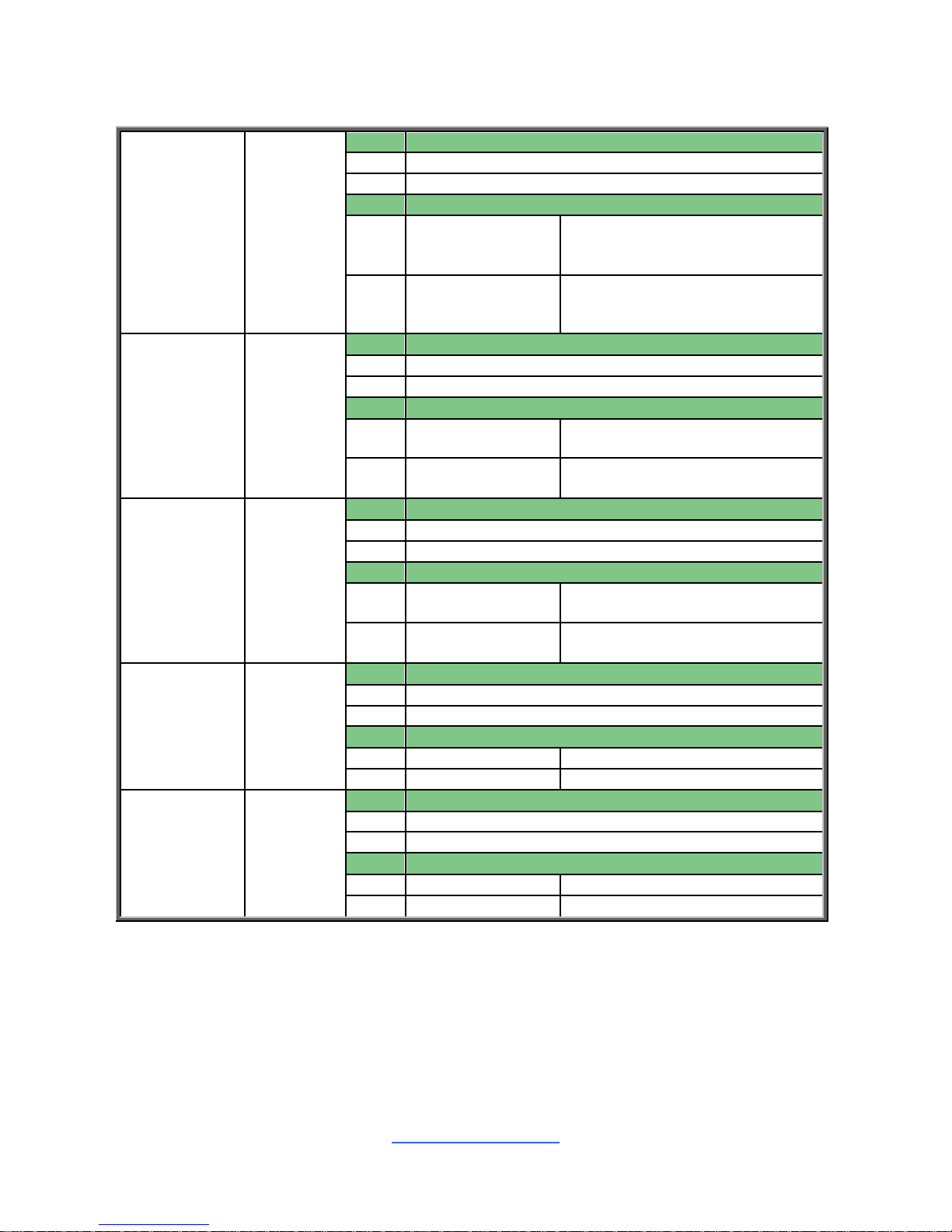
1. Align and install the processor on the carrier.
2. Carefully flip the heatsink. Then install the carrier assembly on the bottom of
the heatsink and make sure the gold arrow is located in the correct direction.
http://www.tyan.com
26
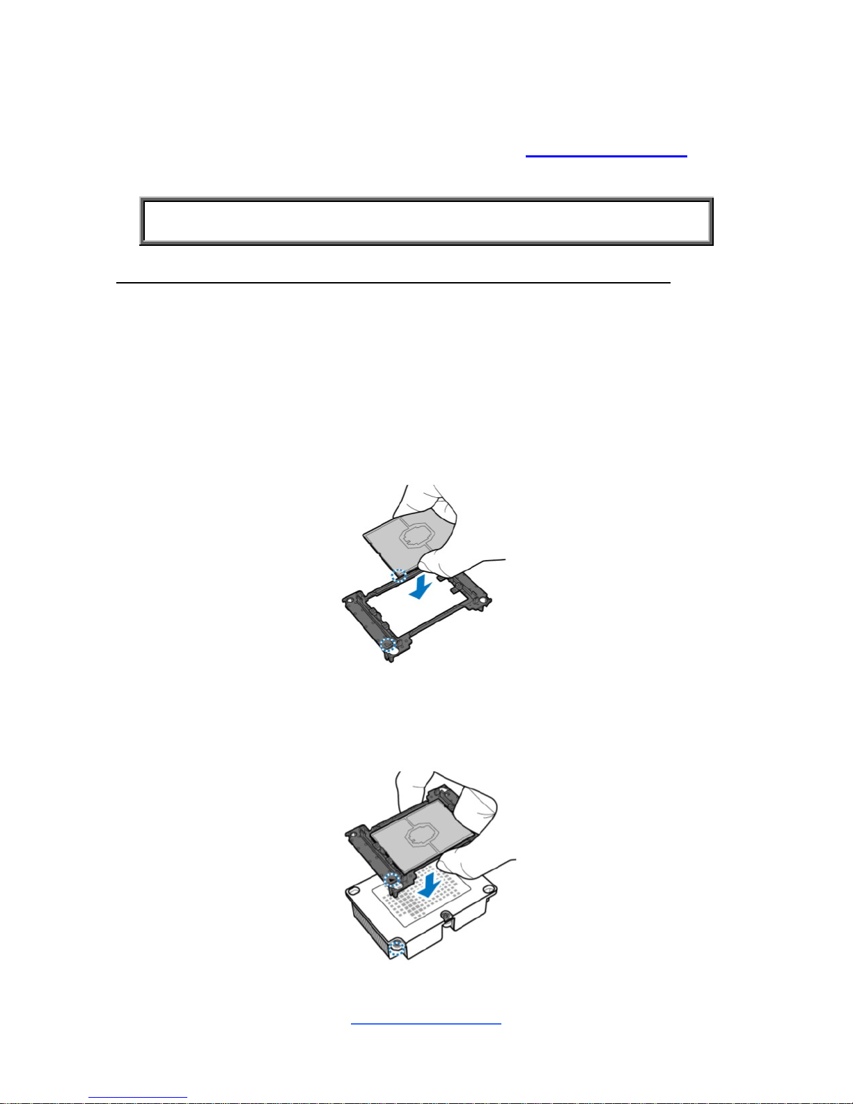
3. Remove the CPU cover. NOTE: Save and replace the CPU cover if the
processor is removed from its socket.
4. Align the heatsink with the CPU socket by the guide pins and make sure the
gold arrow is located in the correct direction. Then place the heatsink onto the
top of the CPU socket.
5. Align the heatsink by the guide pins and make sure the gold arrow is located
in the correct direction. Then place the heatsink onto the top of the processor.
http://www.tyan.com
27
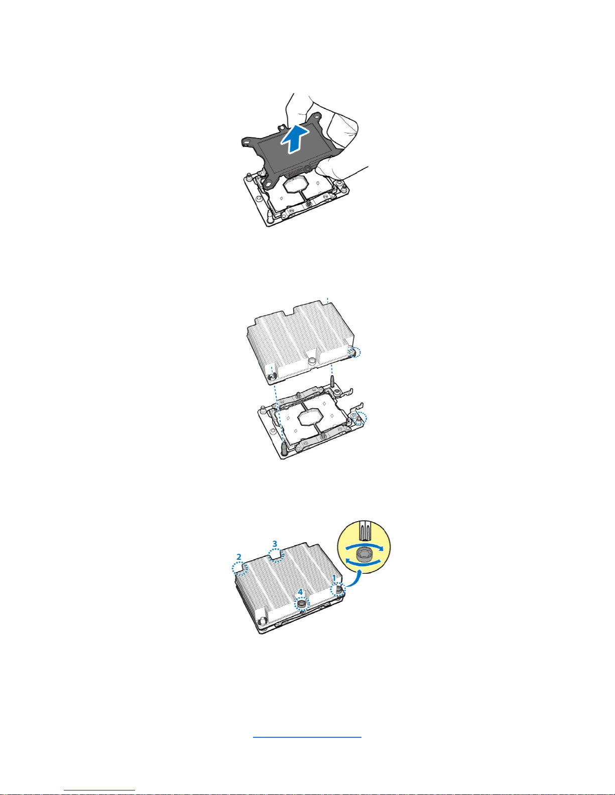
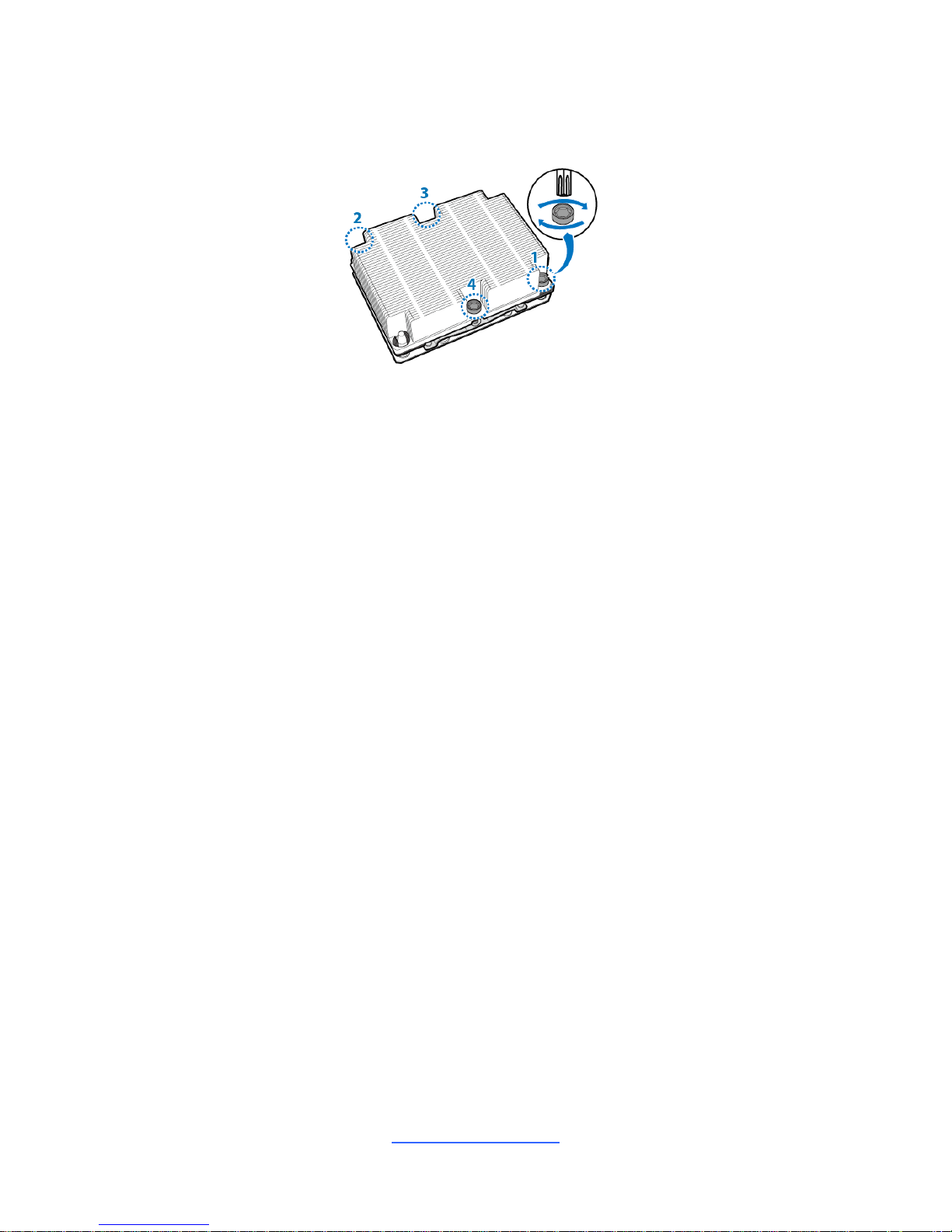
6. To secure the heatsink, use a Security T30 Security Torx to tighten the
screws in a sequential order (1->2->3->4). When dissembling the heatsink,
loosen the screws in reverse order (4->3->2->1).
http://www.tyan.com
28
2.7 Tips on Installing Motherboard in Chassis
Before installing your motherboard, make sure your chassis has the necessary
motherboard support studs installed. These studs are usually metal and are gold in
color. Usually, the chassis manufacturer will pre-install the support studs. If you are
unsure of stud placement, simply lay the motherboard inside the chassis and align
the screw holes of the motherboard to the studs inside the case. If there are any
studs missing, you will know right away since the motherboard will not be able to be
securely installed.
Note: Be especially careful to look for extra stand-offs. If there are any stand-offs
present that are not aligned with a mounting hole on the motherboard, it will likely
short components on the back of the motherboard when installed. This will cause
malfunction and/or damage to your motherboard.
http://www.tyan.com
29
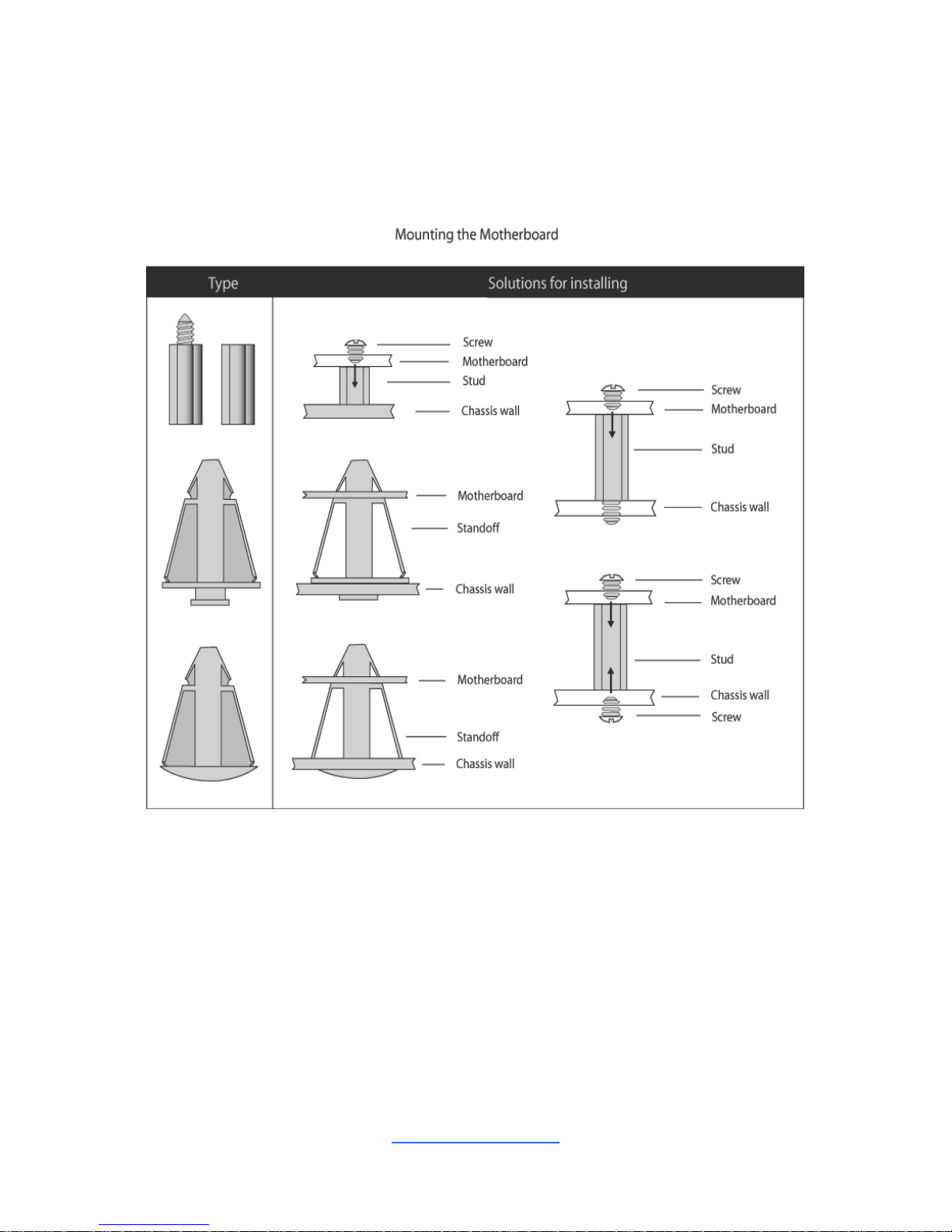
Some chassis include plastic studs instead of metal. Although the plastic studs are
usable, MiTAC recommends using metal studs with screws that will fasten the
motherboard more securely in place.
Below is a chart detailing what the most common motherboard studs look like and
how they should be installed.
http://www.tyan.com
30
2.8 Installing the Memory
Before installing memory, ensure that the memory you have is compatible with the
motherboard and processor. Check the TYAN Web site at http://www.tyan.com for
details of the type of memory recommended for your motherboard.
Support (16)DDR4 288-pin DIMM slots,
Support (6) memory channels per CPU
RDIMM DDR4 2666Mhz w/ ECC (1.2V) when 1DPC
RDIMM DDR4 2133, 2400Mhz w/ ECC (1.2V) when 2DPC. NO 3DPC support
LRDIMM DDR4 2666Mhz w/ ECC (1.2V) when 1DPC
LRDIMM DDR4 2133, 2400Mhz w/ ECC (1.2V) when 2DPC. NO 3DPC support
Channel B, E, 2DPC, others 1DPC
 Loading...