

TYAN S7076 User Manual

http://www.tyan.com
1
S7076
Version 1.0
Copyright
Copyright © 2014 MiTAC International Corporation. All rights reserved. No part of
this manual may be reproduced or translated without prior written consent from
MiTAC International Corporation.
Trademark
All registered and unregistered trademarks and company names contained in this
manual are property of their respective owners including, but not limited to the
following.
TYAN® is a trademark of MiTAC International Corporation.
Intel
®
is a trademark of Intel® Corporation.
AMI, AMI BIOS are trademarks of AMI Technologies.
Microsoft®, Windows® are trademarks of Microsoft Corporation.
Nuvoton
®
is a trademark of Nuvoton Technology Corporation.
Notice
Information contained in this document is furnished by MiTAC International
Corporation and has been reviewed for accuracy and reliability prior to printing.
MiTAC assumes no liability whatsoever, and disclaims any express or implied
warranty, relating to sale and/or use of TYAN
®
products including liability or
warranties relating to fitness for a particular purpose or merchantability. MiT A C
retains the right to make changes to product descriptions and/or specifications at
any time, without notice. In no event will MiTAC be held liable for any direc t or
indirect, incidental or consequential damage, loss of use, loss of data or other
malady resulting from errors or inaccuracies of information contained in this
document.

http://www.tyan.com
2

http://www.tyan.com
3
Contents
Before you begin… .................................................................................... 4
Chapter 1: Instruction ................................................................................ 5
1.1 Congratulations ................................................................................. 5
1.2 Hardware Specifications .................................................................... 5
1.3 Software Specifications ..................................................................... 7
Chapter 2: Board Installation ..................................................................... 9
2.1 Board Image .................................................................................... 10
2.2 Block Diagram ................................................................................. 11
2.3 Mainboard Mechanical Drawing ...................................................... 12
2.4 Board Parts, Jumpers and Connectors ........................................... 13
2.5 LED Definitions ................................................................................ 28
2.6 Installing the Processor and Heat sink ............................................ 31
2.7 Thermal Interface Material .............................................................. 35
2.8 Tips on Installing Motherboard in Chassis ...................................... 36
2.9 Installing the Memory ...................................................................... 38
2.10 Attaching Drive Cables .................................................................. 42
2.11 Installing Add-In Cards .................................................................. 43
2.12 Connecting External Devices ........................................................ 44
2.13 Installing the Power Supply ........................................................... 45
2.14 Finishing Up ................................................................................... 46
Chapter 3: BIOS Setup ............................................................................. 47
3.1 About the BIOS ................................................................................ 47
3.2 Main Menu ....................................................................................... 49
3.3 Advanced Menu ............................................................................... 50
3.4 Intel RC Setup ................................................................................. 79
3.5 Server Management (reserved for BB) ......................................... 108
3.6 Security .......................................................................................... 111
3.7 Boot ............................................................................................... 113
3.8 Save & Exit .................................................................................... 115
Chapter 4: Diagnostics ........................................................................... 117
4.1 Flash Utility .................................................................................... 117
4.2 AMIBIOS Post Code (Aptio) .......................................................... 118
Appendix: Fan and Temp Sensors........................................................ 125
Glossary ................................................................................................... 129
Technical Support .................................................................................. 135
http://www.tyan.com
4
Before you begin…
Check the box contents!
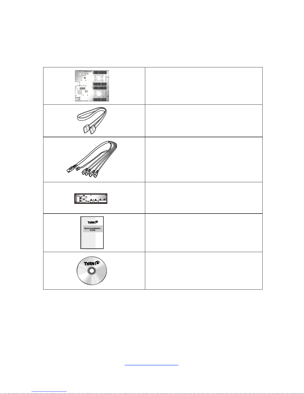
The retail motherboard package should contain the following:
1 x S7076 Motherboard
2 x SATA Cable
1 x Mini-SAS to SATAx4 Cable
1 x Rear IO Shield
1 x S7076 Quick reference guide
1 x TYAN
®
Driver’s and Utilities DVD
IMPORTANT NOTE:
Sales sample may not come with the accessory listed above.
Please contact your sales representative to help order accessory for your
evaluation.

http://www.tyan.com
5
Chapter 1: Instruction
1.1 Congratulations
You have purchased the powerful TYAN® S7076 motherboard, based on the
Intel
®
C612 chipset. The S7076 is designed to support dual Intel® Xeon E5-2600
v3 series processors, and up to 2048GB LRDIMM 3DS/ 1024GB LRDIMM/
512GB RDIMM DDR4 memory. Leveraging advanced technolog y from Intel®, the
S7076 is capable of offering scalable 32 and 64-bit computing, high-bandwidth
memory design, and lightning-fast PCI-E bus implementation.
The S7076 not only empowers you in today’s demand ing IT environment but also
offers a smooth path for future application upgradeability. All of these rich feature
sets provides the S7076 with the power and flexibility to meet demanding
requirements for today’s IT environments.
Remember to visit the TYAN® website at http://www.tyan.com. There you can
find all the information on all TYAN® products as well as all the supporting
documentation, FAQs, Drivers and BIOS upgrades.
1.2 Hardware Specifications
TYAN S7076 (S7076GM2NR)
Processor
Supported CPU
Series
Intel Xeon Processor E5-2600 v3 series
Socket Type / Q'ty Socket-R3 (LGA2011) / (2)
Thermal Design
Power (TDP)
wattage
Max up to 160W
System Bus
Up to 9.6/ 8.0/ 6.4 GT/s with Intel QuickPath
Interconnect (QPI) support
Chipset PCH Intel C612
Memory
Supported DIMM
Qty
(8)+(8) DIMM slots
DIMM Type / Speed
RDIMM DDR4 2133/1866/1600 / LRDIMM 3DS DDR4
2133/1600 / LRDIMM DDR4 2133/1600
Capacity
Up to 2048GB LRDIMM 3DS/ 1024GB LRDIMM/ 512GB
RDIMM
Memory channel 4 Channels per CPU
Memory voltage 1.2V
Expansion
Slots
PCI-E (2) PCI-E x8 Gen.3 slots
Recommended
TYAN Riser Card
M2091, PCI-E x16 1U riser card (left) / M2103-L8-1L,
Proprietary PCI-E 1U riser (right)

http://www.tyan.com
6
Recommended
TYAN Mezzanine
Card
M7062-B811-1T, PCI-E Gen3 x8 slot, Broadcom 10GbE
Mezz Card / M7062-B810-2T, PCI-E Gen3 x8 slot,
Broadcom 10GbE Mezz Card / M7076-IX540-2T, PCI-E
Gen3 x8 slot, Intel 10GbE Mezz Card / M7076-12G-8I,
PCI-E Gen3 x8 slot, LSI SAS 12G Mezz Card / M70946G-8I, PCI-E Gen3 x8 slot, LSI SAS 6G Mezz Card /
M7076-6G-8I, PCI-E Gen3 x8 slot, LSI SAS 6G Mezz
Card
Note:
(1) OCP slot for Mezz Card; (1)Proprietary slot for SAS
Mezz Card
LAN
Port Q'ty (2) GbE ports (LAN1 shared with IPMI)
Controller Intel I350-AM2
Storage
SATA
Connector
(6) SATA* + SGPIO1 (J43)
NOTE: SATA0~SATA3 (J41) , SATA 4 (J45), SATA5
(J46)
Controller Intel C612
Speed 6.0 Gb/s
RAID RAID 0/1/10/5 (Intel RST)
sSATA
Connector
(4) sSATA* + SGPIO2 (within J42)
NOTE: sSATA0~SATA3 (J42)
Controller Intel C612
Speed 6.0 Gb/s
RAID RAID 0/1/10/5 (Intel RST)
Graphic
Connector type D-Sub 15-pin
Resolution Up to 1920x1200
Chipset Aspeed AST2400
Input /Output
USB
(3) USB2.0 ports (2 via cable, 1 vertical type-A
connector) / (4) USB3.0 ports (2 at rear, 2 via cable)
COM (2) ports (COM1 at rear, COM2 via cable)
VGA (1) D-Sub 15-pin VGA port
RJ-45 Total (2) GbE ports, LAN1 shared with IPMI
Power SSI 24-pin + 8-pin + 8-pin power connectors
PSMI (1) 1x5-pin header
SATA
(2) SATA-III connectors + (2) Mini-SAS (4-in-1)
connectors
System
Monitoring
Chipset Aspeed AST2400
Voltage
Monitors voltage for CPU, memory, chipset & power
supply
Fan Total (7) 4-pin headers
Temperature Monitors temperature for CPU & system environment
LED
Over temperature warning indicator / Fan & PSU fail
LED indicator
NOTE: The LED signal is connected to the Front Panel
Header on the motherboard. This is the warning led on
the front panel board preinstalled in the barebone.
http://www.tyan.com
7
Others Watchdog timer support
Server
Management
Onboard Chipset Onboard Aspeed AST2400
AST2400 IPMI
Feature
IPMI 2.0 compliant baseboard management controller
(BMC) / Supports storage over IP and remote platform-
flash / USB 2.0 virtual hub
AST2400 iKVM
Feature
24-bit high quality video compression / 10/100 Mb/s
MAC interface
BIOS
Brand / ROM size AMI / 16MB
Feature
User-configurable H/W monitoring / SMBIOS
2.7/PnP/Wake on LAN / PXE boot support / ACPI
3.0/ACPI sleeping states S0,S4,S5
Physical
Dimension
Form Factor EATX
Board Dimension 12"x13" (305x330mm)
Operating
System
OS supported list Please refer to our Intel OS supported list.
Regulation
FCC (DoC) Class A
CE (DoC) Yes
Operating
Environment
Operating Temp. 10° C ~ 35° C (50° F~ 95° F)
Non-operating
Temp.
- 40° C ~ 70° C (-40° F ~ 158° F)
In/Non-operating
Humidity
90%, non-condensing at 35° C
RoHS
RoHS 6/6
Compliant
Yes
Package
Contains
Motherboard (1) S7076 Motherboard
Manual (1) Quick Installation Guide
Installation CD (1) TYAN installation CD
1.3 Software Specifications
For OS (operation system) support, please check with TYAN® support for latest
information.

http://www.tyan.com
8
NOTE

http://www.tyan.com
9
Chapter 2: Board Installation
You are now ready to install your motherboard.
How to install our products right… the first time
The first thing you should do is reading this user’s manual. It contains important
information that will make configuration and setup much easier. Here are some
precautions you should take when installing your motherboard:
(1) Ground yourself properly before removing your motherboard from the
antistatic bag. Unplug the power from your computer power supply and
then touch a safely grounded object to release static charge (i.e. power
supply case). For the safest conditions, MiTAC recommends wearing a
static safety wrist strap.
(2) Hold the motherboard by its edges and do not touch the bottom of the
board, or flex the board in any way.
(3) Avoid touching the motherboard components, IC chips, connectors,
memory modules, and leads.
(4) Place the motherboard on a grounded antistatic surface or on the antist ati c
bag that the board was shipped in.
(5) Inspect the board for damage.
The following pages include details on how to install your motherboard into your
chassis, as well as installing the processor, memory, disk drives and cables.
NOTE: Do not apply power to the board if it has been damaged.
http://www.tyan.com
10
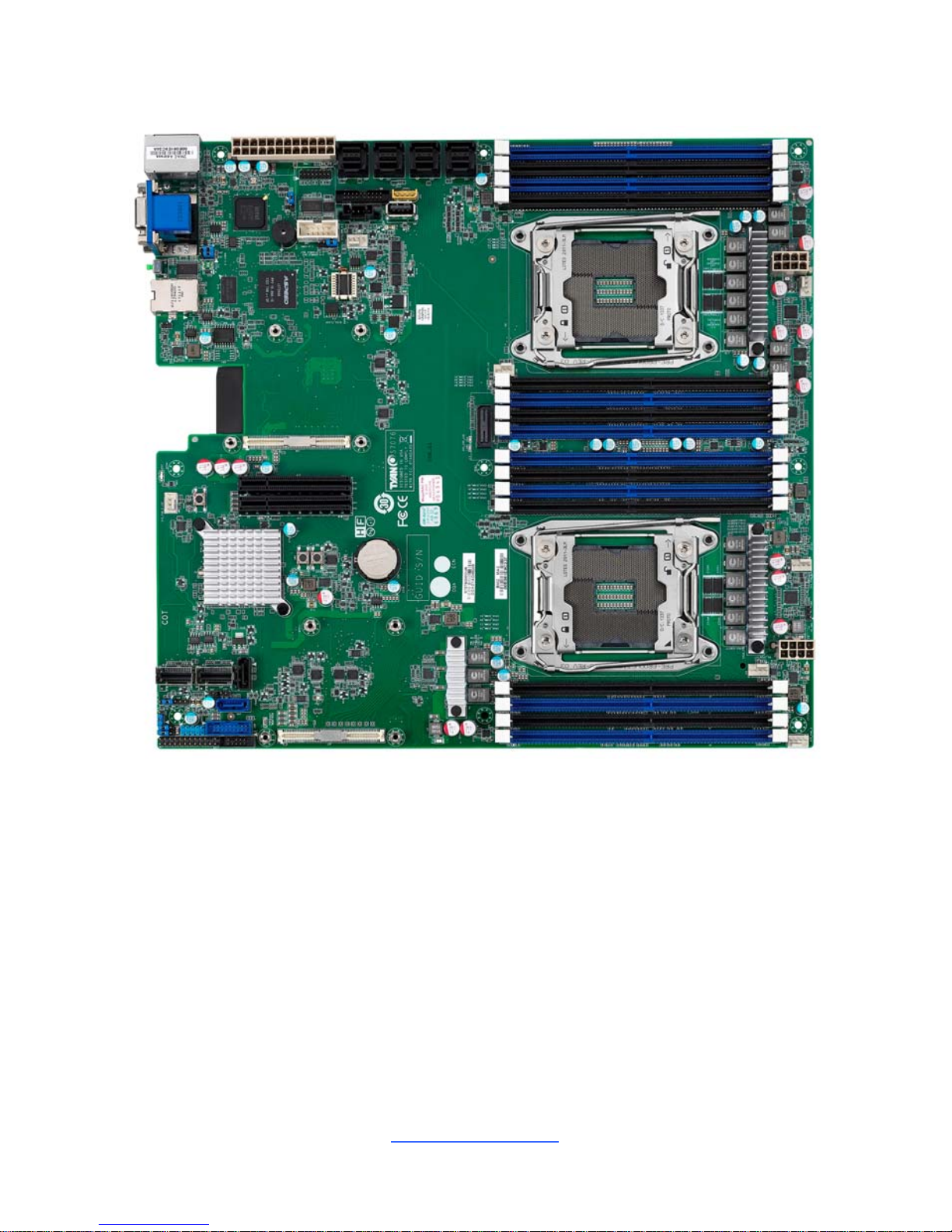
2.1 Board Image
S7076
This picture is representative of the latest board revision available at the time of
publishing. The board you receive may not look exactly like the above picture.
http://www.tyan.com
11
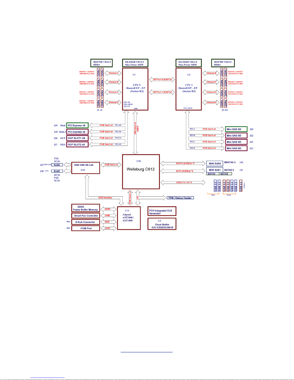
2.2 Block Diagram
S7076 Block Diagram
http://www.tyan.com
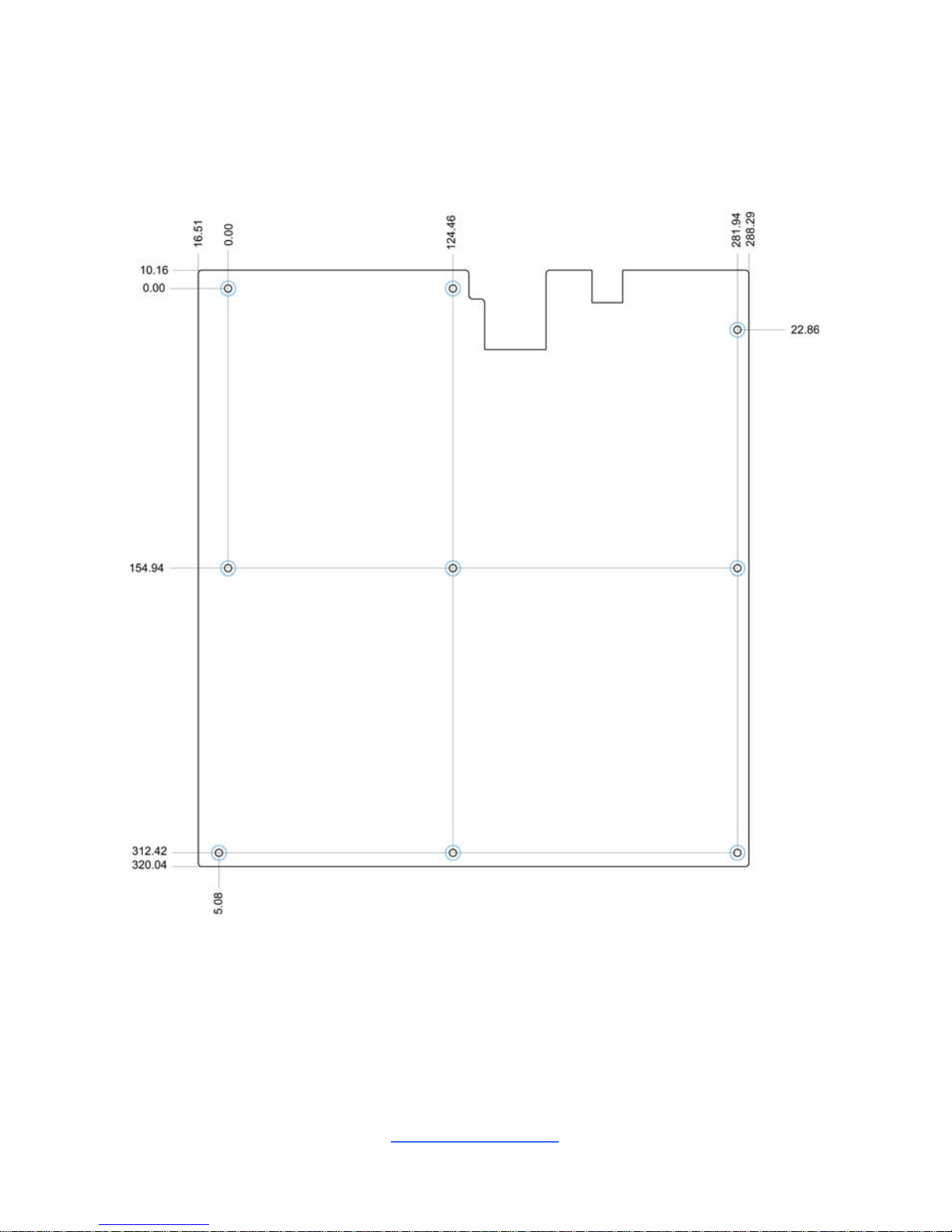
12
2.3 Mainboard Mechanical Drawing
http://www.tyan.com
13
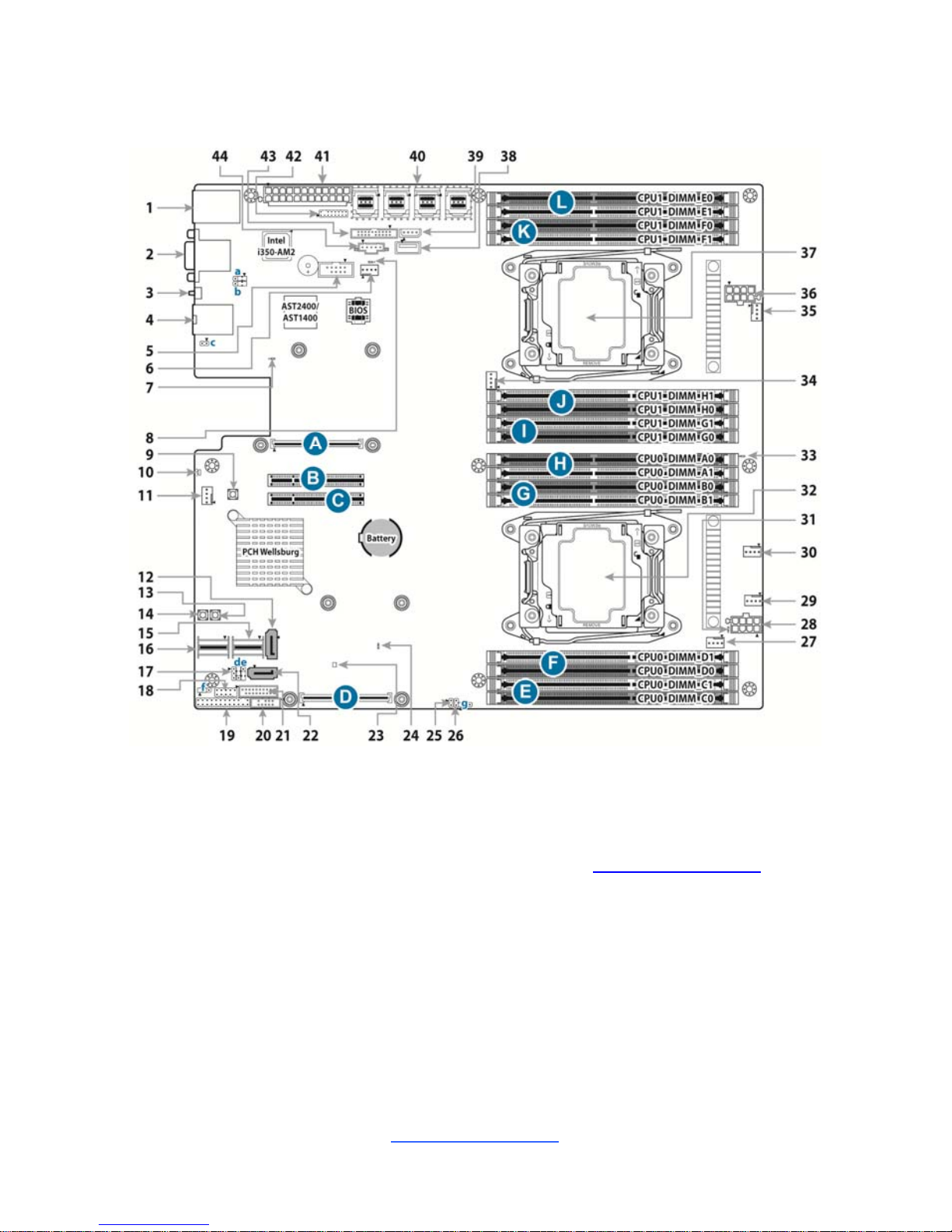
2.4 Board Parts, Jumpers and Connectors
This diagram is representative of the latest board revision available at the time of
publishing. The board you receive may not look exactly like the above diagram. But
for the DIMM number please refer to the above placement for memory installation.
For the latest board revision, please visit our web site at http://www.tyan.com.
http://www.tyan.com
14
Jumpers & Connectors
Connector/Jumper
1 LAN2 + USB 3.0 x 2 23 PCH PWROK LED (LED2)
2 VGA / COM1 24 CAT Error LED (LED3)
3 ID LED Button (SW3) 25 ID LED Button Header (J56)
4 LAN1 26 Chassis Intrusion Header (J57)
5 COM2 Header (J68) 27 CPU0 FAN (J28)
6 SYS_FAN_4 (J31)
28 SSI 8-pin CPU0 Power Connector
(PW1)
7 BMC LED (LED1) 29 SYS_FAN_3 (J35)
8 PSU Alert LED (LED10) 30 SYS_FAN_2 (J34)
9 Clear CMOS Button (SW4) 31 CPU0 PWOK LED (LED8)
10 Rear ID LED (LED7) 32 CPU0 Socket (U1)
11 SYS_FAN_5 (J32) 33 CPU1 PWOK LED (LED9)
12 7-pin Vertical SATA3.0 Connector
(SATA5, J46)
34 CPU1 FAN (J30)
13 Reset Button (SW2) 35 SYS_FAN_1 (J33)
14 Power Button (SW1)
36 SSI 8-pin CPU1 Power Connector
(PW3)
15 SATA0~SATA3 (J41) 37 CPU1 Socket (U2)
16 sSATA0~sSATA3 (J42)
38 Vertical Type-A USB2.0
Connector (J40)
17 HOST SMBUS Header (J61) 39 IPMB Pin Header (J51)
18 USB2.0 Header (J37)
40 Mini-SAS HD Connector
(J20/J21/J22/J23)
19 Front Panel Header (J50)
41 ATX 24-pin Main Power
Connector (PW2)
20 PCH SATA SGPIO Header for BB
HD Board (J43)
42 TYAN Module Header (J48)
21 USB3.0 Header (J36)
43 FAN Header for BB FAN Board
(J29)
22 7-pin Vertical SATA3.0 Connector
(SATA4, J45)
44 PSMI Pin Header (J49)
Jumpers Slots
a COM2 or COM5 Selected Jumper
(J64)
A OCP Slot for OCP Mezz Card (J26)
b COM2 or COM5 Selected Jumper
(J63)
B PCI-E 3.0x8 Slot (x8 link, open-end
type, #PCIe-6.5)
c BMC Reset Header (J55)
C PCI-E 3.0x8 Slot (x8 link, open-end
type, #PCIe-6)
d BIOS Recovery Mode Jumper (J58)
D Proprietary Slot for SAS Mezz Card
(J27)
http://www.tyan.com
15
e NMI Jumper (J67)
E CPU0_DIMM_C0/C1
f ME Recovery Mode Jumper (J62) F CPU0_DIMM_D0/D1
g ME Security Override Jumper (J60) G CPU0_DIMM_B0/B1
H CPU0_DIMM_A0/A1
I CPU1_DIMM_G0/G1
J CPU1_DIMM_H0/H1
K CPU1_DIMM_F0/F1
L CPU1_DIMM_E0/E1
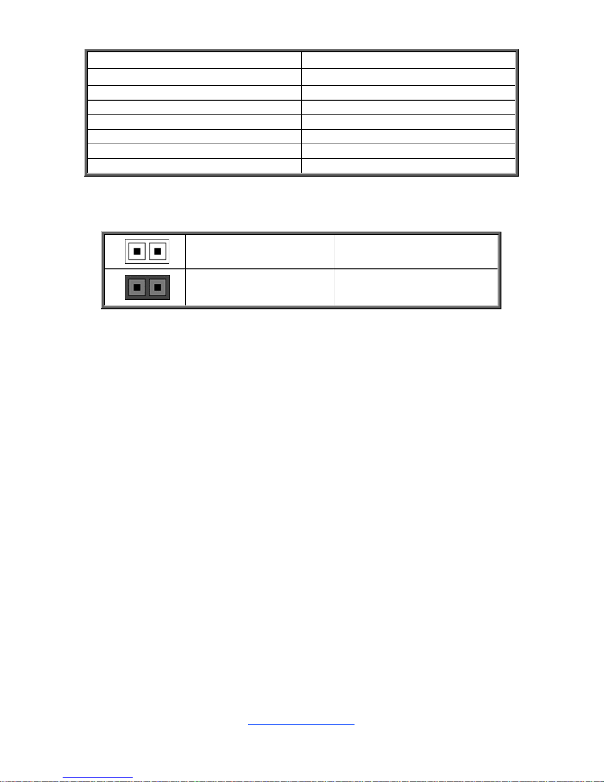
Jumper Legend
OPEN - Jumper OFF
Without jumper cover
CLOSED - Jumper ON
With jumper cover
http://www.tyan.com
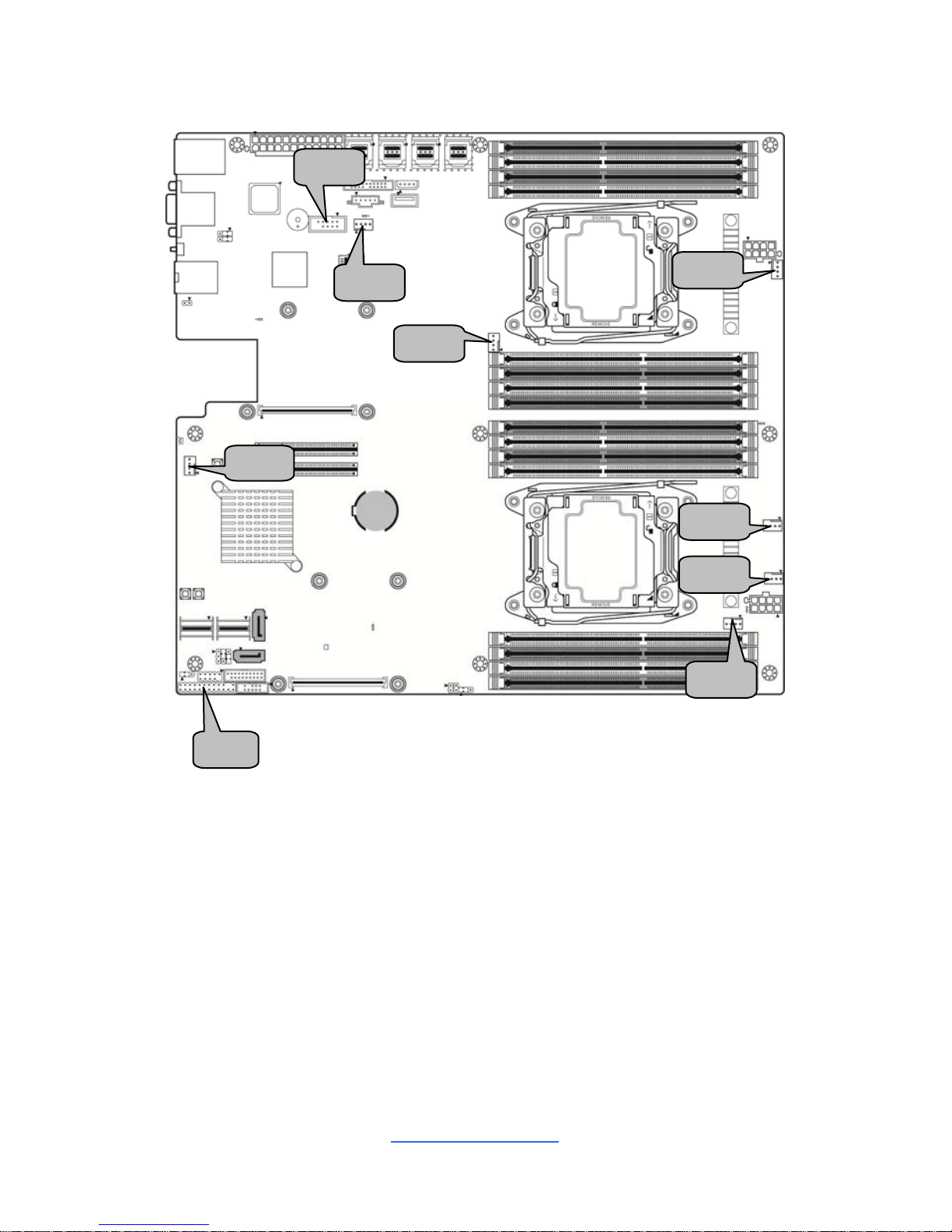
16
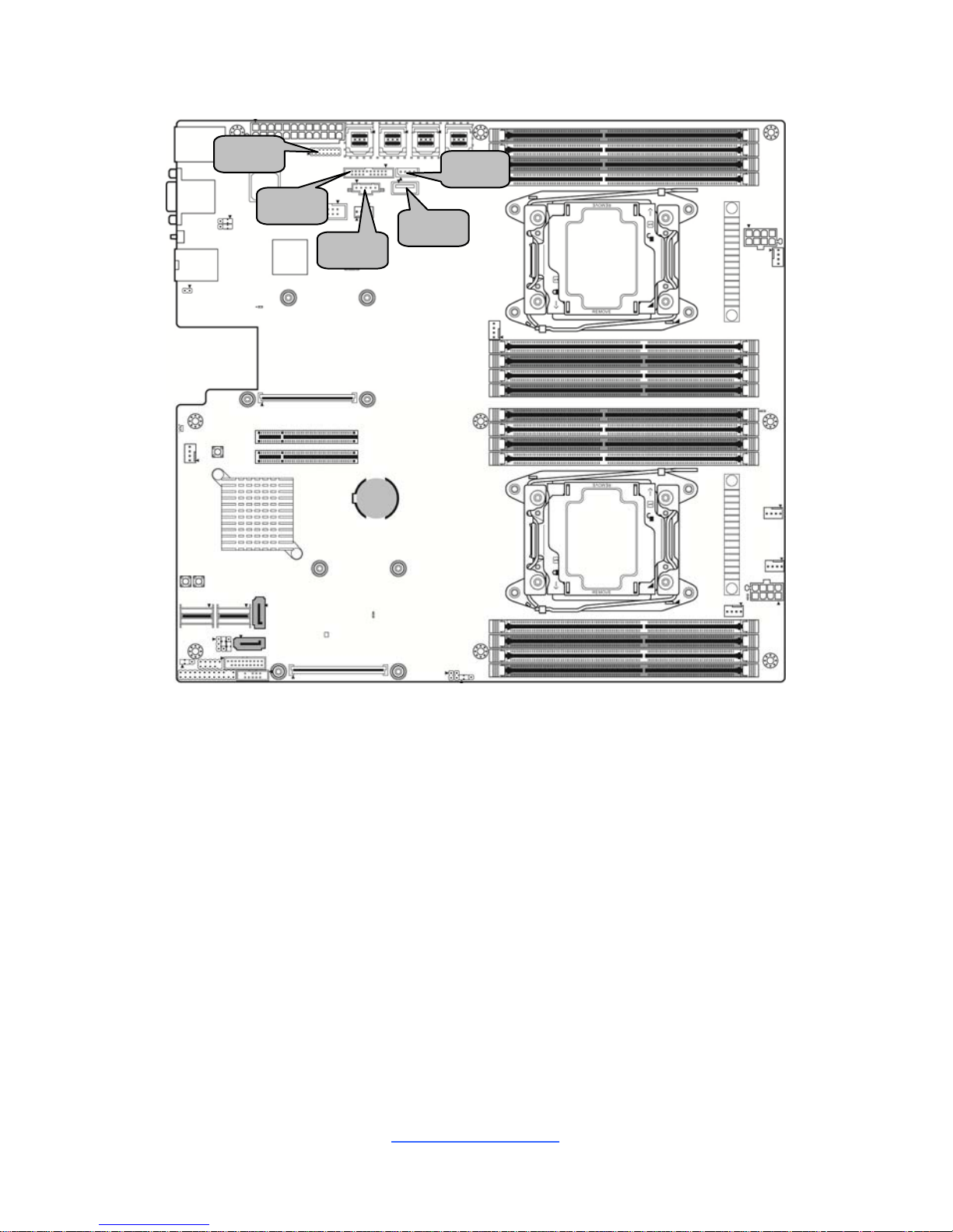
J33
J28
J68
J30
J31
J
3
2
J50
J35
J34
http://www.tyan.com
17
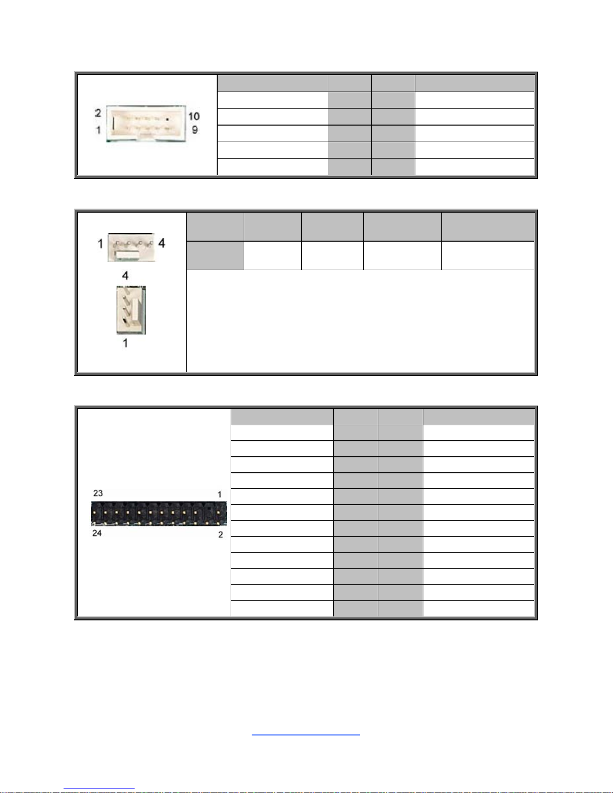
J68: COM Port Header
Signal Pin Pin Signal
COM2_DCD
1 2
COM2_DSR
COM2_RXD
3 4
COM2_RTS
COM2_TXD
5 6
COM2_CTS
COM2_DTR
7 8
COM2_NRI
GND
9 10
NC
J28/J30/J31/J32/J33/J34/J35: 4-pin FAN Connector
Pin 1 2 3 4
Signal GND VCC12 FAN_TACH FAN_PWM
Use this header to connect the cooling fan to your motherboard to
keep the system stable and reliable.
J28: CPU0 FAN J30: CPU1 FAN J31: SYS_FAN_4
J32: SYS_FAN_5 J33: SYS_FAN_1 J34: SYS_FAN_2
J35: SYS_FAN_3
J50: Front Panel Header
Signal Pin Pin Signal
FP_PW_LED_PW 1 2 FP_PWR
KEY 3 4 FP_ID_LED_PW
PWR_LED- 5 6 FP_ID_LED_N
HDD_LED+ 7 8 LED_FAULT1
HDD_LED- 9 10 LED_FAULT2
FP_PWRSW# 11 12 LAN0_ACT_P
GND 13 14 LAN0_LED1_ACT#
FP_RSTSW# 15 16 FP_SMBDAT
GND 17 18 FP_SMBCLK
FP_IDLEDSW# 19 20 FP_INTRUSION#
NC 21 22 LAN1_ACT_P
FP_NMISW# 23 24 LAN1_LED1_ACT#
http://www.tyan.com
18
J46
J37
J57
J36
J45
J56
http://www.tyan.com
19
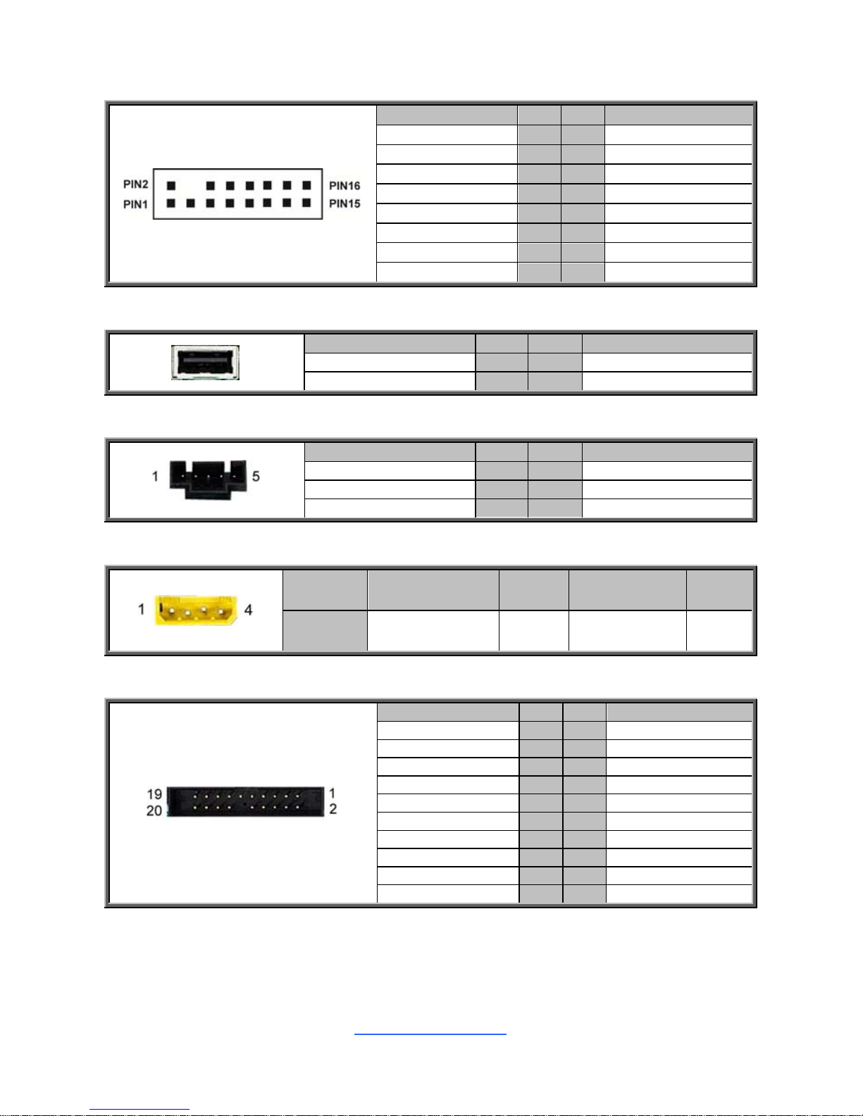
J56: Front Panel ID LED
Signal Pin Pin Signal
FP_IDLEDSW# 1 2 GND
J57: Chassis Intrusion Header
Signal Pin Pin Signal
INTRUDER# 1 2 GND
J37: Front USB2.0 Header (blue)
Signal Pin Pin Signal
USB2_VCC_REAR_2
1 2
USB2_VCC_REAR_2
USB2_N3_REAR_3_R
3 4
USB2_N4_REAR_2_R
USB2_P3_REAR_3_R
5 6
USB2_P4_REAR_2_R
GND
7 9
GND
KEY
9 10
OPEN
J45/J46: 7-pin Vertical SATA3.0 Connector
PIN Define Pin
Connects to the Serial
ATA ready drives via
the Serial ATA cable.
J45: SATA4
J46: SATA5
1
GND
2
SATA_TXP_C
3
SATA_TXN_C
4
GND
5
SATA_RXN_C
6
SATA_RXP_C
7
GND
J36: USB3.0 Header
Signal Pin Pin Signal
USB3_VCC_FPB_01
1 20
KEY
USB3_N5_RX_FPB_N0
2 19
USB3_VCC_FPB_01
USB3_P5_RX_FPB_P0
3 18
USB3_N6_RX_FPB_N1
GND
4 17
USB3_P6_RX_FPB_P1
USB3_N5_TX_FPB_N0
5 16
GND
USB3_P5_TX_FPB_P0
6 15
USB3_N6_TX_FPB_N1
GND
7 14
USB3_P6_TX_FPB_P1
USB2_N12_FPB_N0_R
8 13
GND
USB2_P12_FPB_P0_R
9 12
USB2_N11_FPB_N1_R
OC_N
10 11
USB2_P11_FPB_P1_R
http://www.tyan.com
20
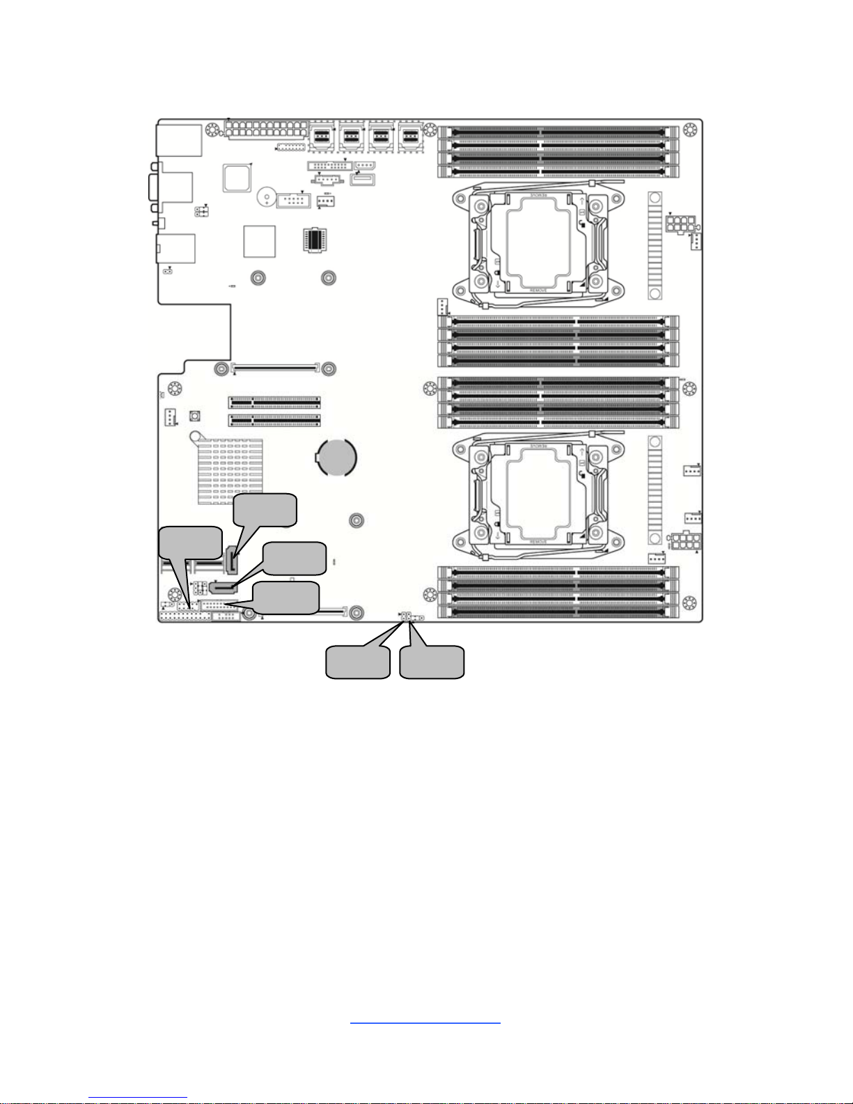
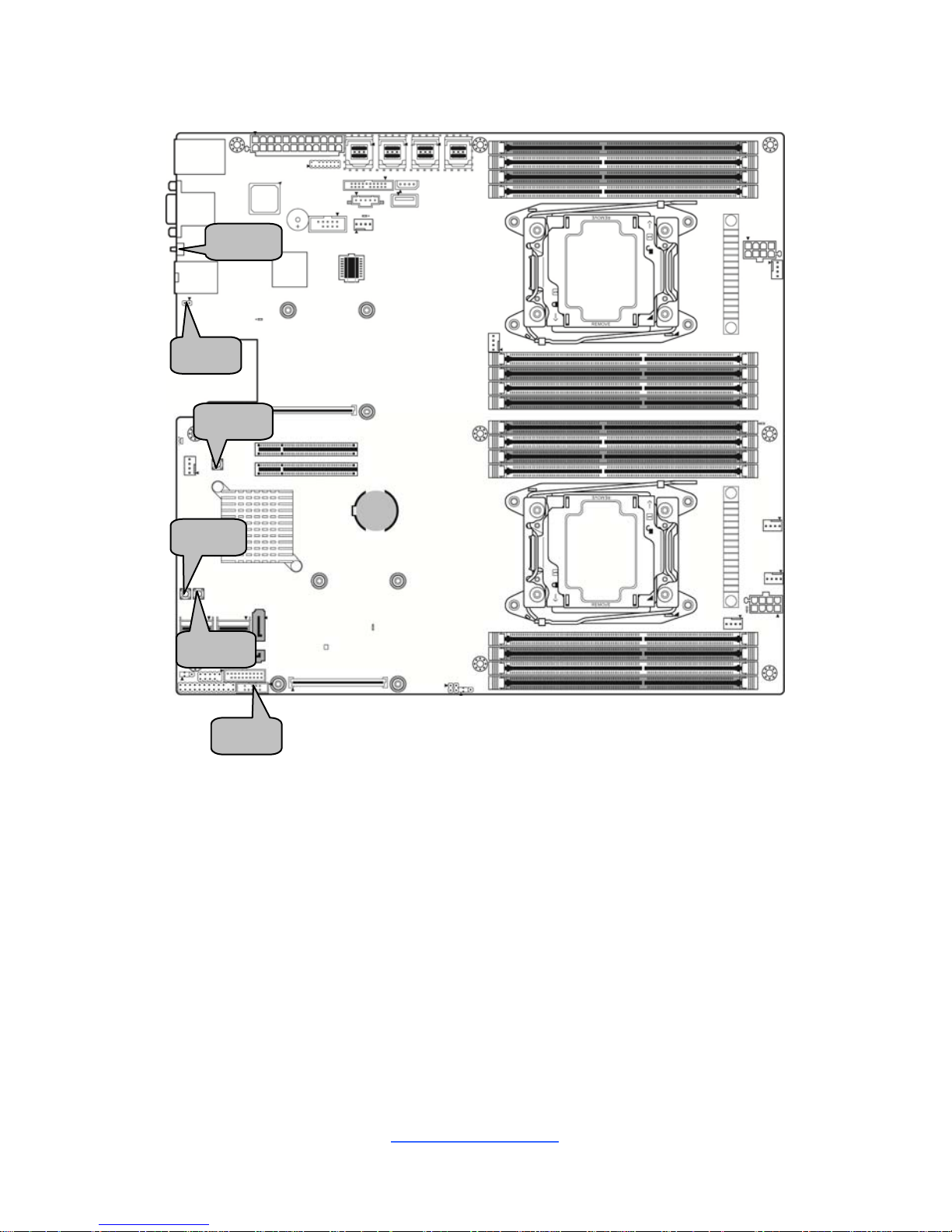
J49
J48
J40
J51
J29
http://www.tyan.com
21
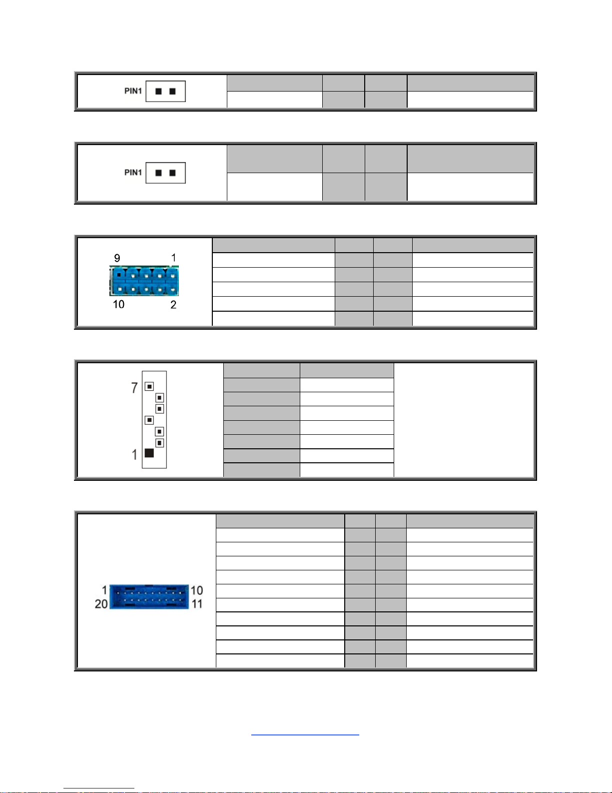
J48: TYAN Module Header
Signal Pin Pin Signal
VCC3 1 2 DBG_LFRAME_N
DBG_LPC0 3 4 KEY
DBG_LPC1 5 6 TPM_RST#
DBG_LPC2 7 8 GND
DBG_LPC3 9 10 CLK_33M_TPM
DBG_SERIRQ 11 12 GND
DBG_PRES_N 13 14 VCC3_AUX
TPM_ADDR_MB 15 16 PCH_TPM_PP_EN
J40: Vertical Type-A USB Connector
Signal Pin Pin Signal
USB_VCC_TYPE_A 1 2 USB_N2_TYPE_A1_R
USB_P2_TYPE_A1_R 3 4 GND
J49: PSMI Connector
Signal Pin Pin Signal
PSMI_5V_SMBCLK 1 2 PSMI_5V_SMBDATA
PSU_ALERT_N 3 4 GND
VCC3 5
J51: IPMB Pin Header
Pin 1 2 3 4
Signal IPMB DATA GND IPMB CLK VCC
J29: Fan Connector Reserved for Barebone
Signal Pin Pin Signal
FAN_T1 1 2 FAN_T6
FAN_T2 3 4 FAN_T7
FAN_T3 5 6 FAN_T8
FAN_T4 7 8 FAN_T9
FAN_T5 9 10 FAN_T10
GND 11 12 KEY
PWM_REAR12 13 14 PWM_FRONT3
FAN_T11 15 16 FAN_SDA
FAN_T12 17 18 FAN_SCK
VCC3_AUX 19 20 PWM_BB3
http://www.tyan.com
22
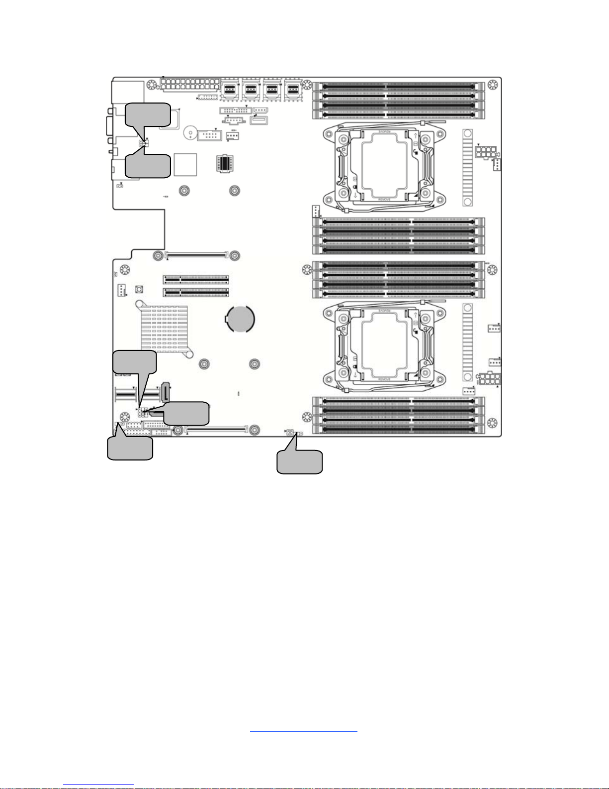
J55
J43
SW4
SW3
SW2
SW1

http://www.tyan.com
23
J43: PCH SGPIO Pin Header
Signal Pin Pin Signal
SATA4_5_SM_CLK 1 2 NC
SATA4_5_SM_DAT 3 4 SGPIO_SATA_DATAOUT0_R2
GND 5 6 SGPIO_SATA_LOAD_R2
KEY 7 8 SGPIO_SATA_CLK_R2
VCC3_AUX 9 10 SATA_ERR_P
J55: BMC Reset Header
Signal Pin Pin Signal
BMC_JP_N 1 2 GND
SW3 (J56): ID LED Switch Button
Signal Pin Pin Signal
FP_IDLED_BTN_N 1 2 GND
GND 3 4 GND
SW1: Power Switch Button
Signal Pin Pin Signal
FP_PWR_BTN_N 1 2 FP_PWR_BTN_N
GND 3 4 GND
SW2: Reset Switch Button
Signal Pin Pin Signal
FP_RST_BTN_N 1 2 FP_RST_BTN_N
GND 3 4 GND
SW4: Clear CMOS Reset Button
You can reset the CMOS settings by using this button, if you have
forgotten your system/setup password or need to clear system BIOS
setting.
1. Power off the system and disconnect power connectors from the
motherboard.
2. Press the button (Clear CMOS).
3. Reconnect power & power on the system.
NOTE: After flashing new BIOS, do the following steps:
a. Clear CMOS
b. Enter BIOS setup menu and load Default Settings. Then do a Save
and Exit from setup.
http://www.tyan.com
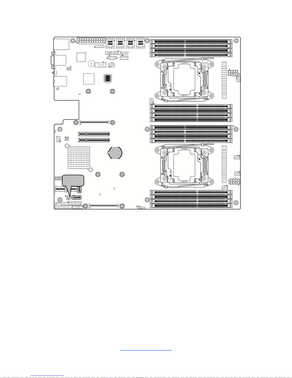
24
J64
J63
J58
J61
J60
J62
http://www.tyan.com
25
J61: HOST SMB Header
Signal Pin Pin Signal
PCH_HOST_3V3STBY_
SMB_DAT
1 2 GND
PCH_HOST_3V3STBY_
SMB_CLK
3
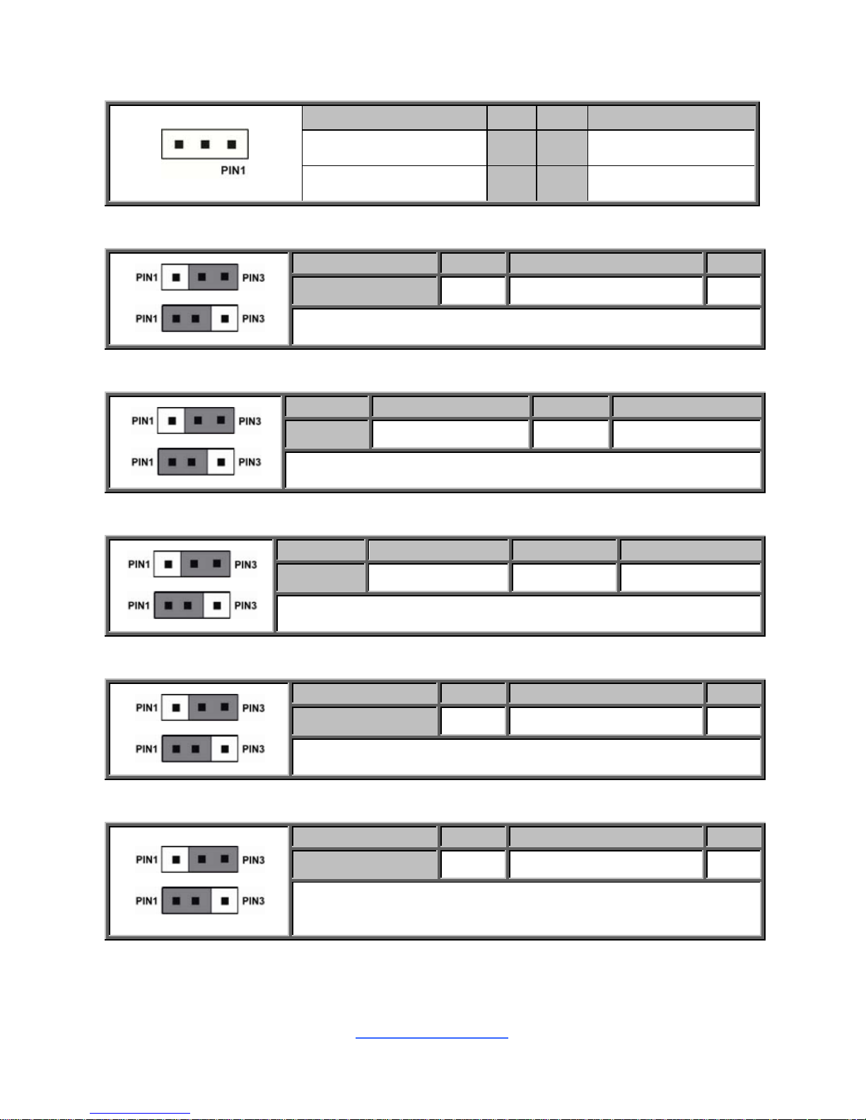
J58: BIOS Recovery Mode Jumper
Pin 1 2 3
Signal OPEN BIOS_RCVR_BOOT_N GND
Pin1-2 closed: Normal (Default)
Pin2-3 closed: BIOS Recovery Mode
J63: COM2 or COM5 Selected Jumper
Pin 1 2 3
Signal BMC_COM2_RXD RXD_2 BMC_COM5_RXD
Pin1-2 closed: COM2 (Default)
Pin2-3 closed: COM5
J64: COM2 or COM5 Selected Jumper
Pin 1 2 3
Signal BMC_COM2_TXD TXD_2 BMC_COM5_TXD
Pin1-2 closed: COM2 (Default)
Pin2-3 closed: COM5
J62: ME Firmware Recovery Mode Jumper
Pin 1 2 3
Signal OPEN FM_ME_RCVR_N GND
Pin1-2 closed: Normal (Default)
Pin2-3 closed: ME Firmware Recovery Mode
J60: Flash Descriptor Security Override Header
Pin 1 2 3
Signal OPEN MFG_MODE_N GND
Pin1-2 closed: Enable security measures defined in the Flash
Descriptor-Normal (Default)
Pin2-3 closed: Disable Flash Descriptor Security (override)
http://www.tyan.com
26
J67
http://www.tyan.com
27
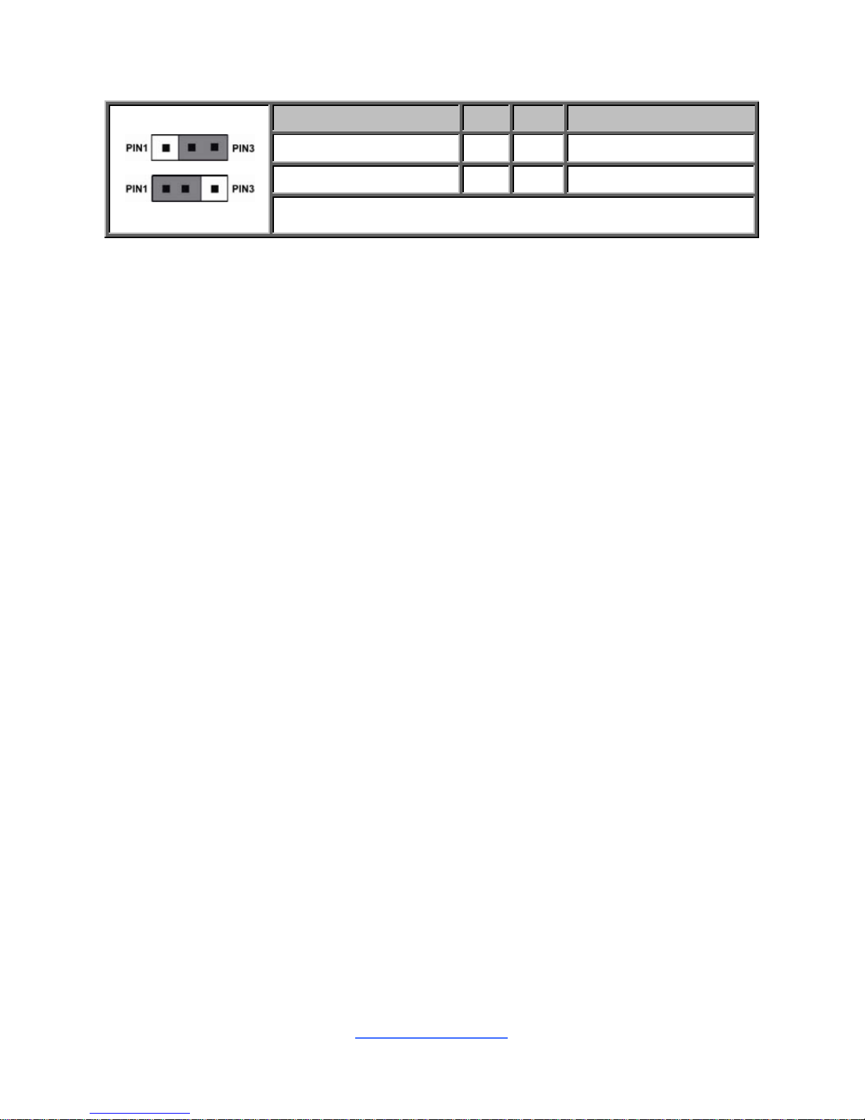
J67: NMI Jumper
Signal Pin Pin Signal
FP_NMI_BTN_N 1 2 FP_PIN23_N
FP_HD_FAULT_LED 3
Pin1-2 closed: Normal (Default)
Pin2-3 closed: Remove NMI Button Function
http://www.tyan.com
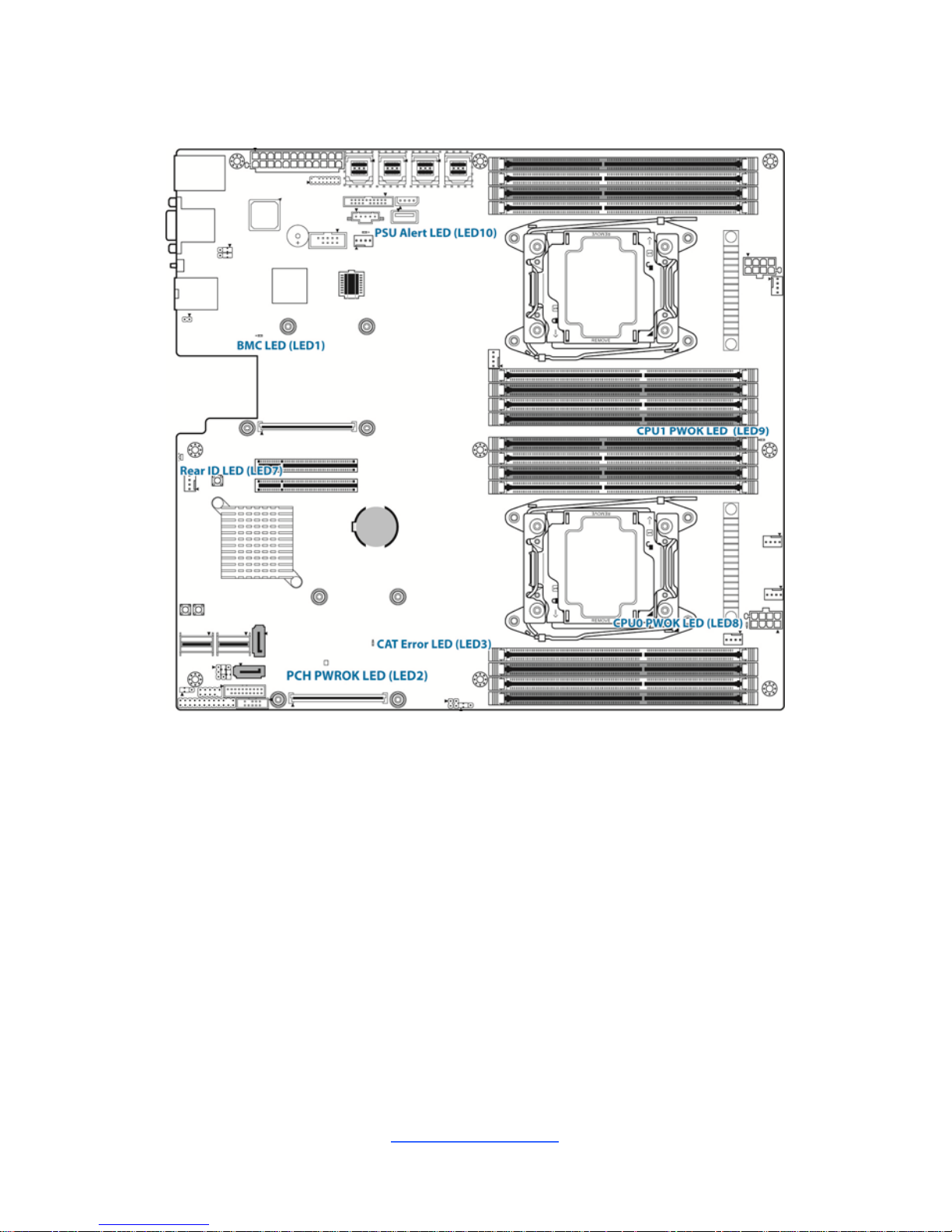
28
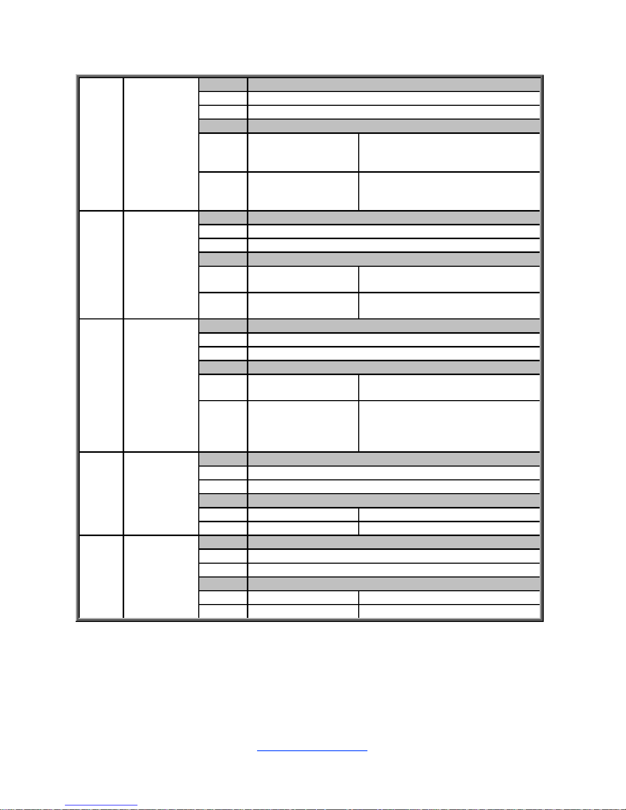
2.5 LED Definitions
http://www.tyan.com
29
LED1
BMC Heart
Beat LED
Pin Signal
+ +3V_AUX
- GND
State Description
OFF OFF
The LED shuts off when the BMC
controller cannot be detected or
properly initiated.
Blinking Green
The LED blinks per second to
indicate that the BMC controller is
working normally
LED2
PCH PWOK
LED
Pin Signal
+ +3V
- GND
State Description
OFF OFF
The LED shuts off when the power
of PCH is abnormal.
ON Amber
The amber LED lights up when the
power of PCH is normal.
LED3
CAT Error
LED
Pin Signal
+ +3V
- GND
State Description
OFF OFF
The LED shuts off when System is
running normally.
ON Red
The LED lighted up when the
system has experienced a fatal or
catastrophic error and can not
continue to operate.
LED7
Rear ID
LED
Pin Signal
+ + VCC3_AUX
- GND
State Description
OFF OFF OFF
ON Green ON
LED8
CPU0
PWOK LED
Pin Signal
+ +3V
- GND
State Description
OFF OFF OFF
ON Green ON
http://www.tyan.com
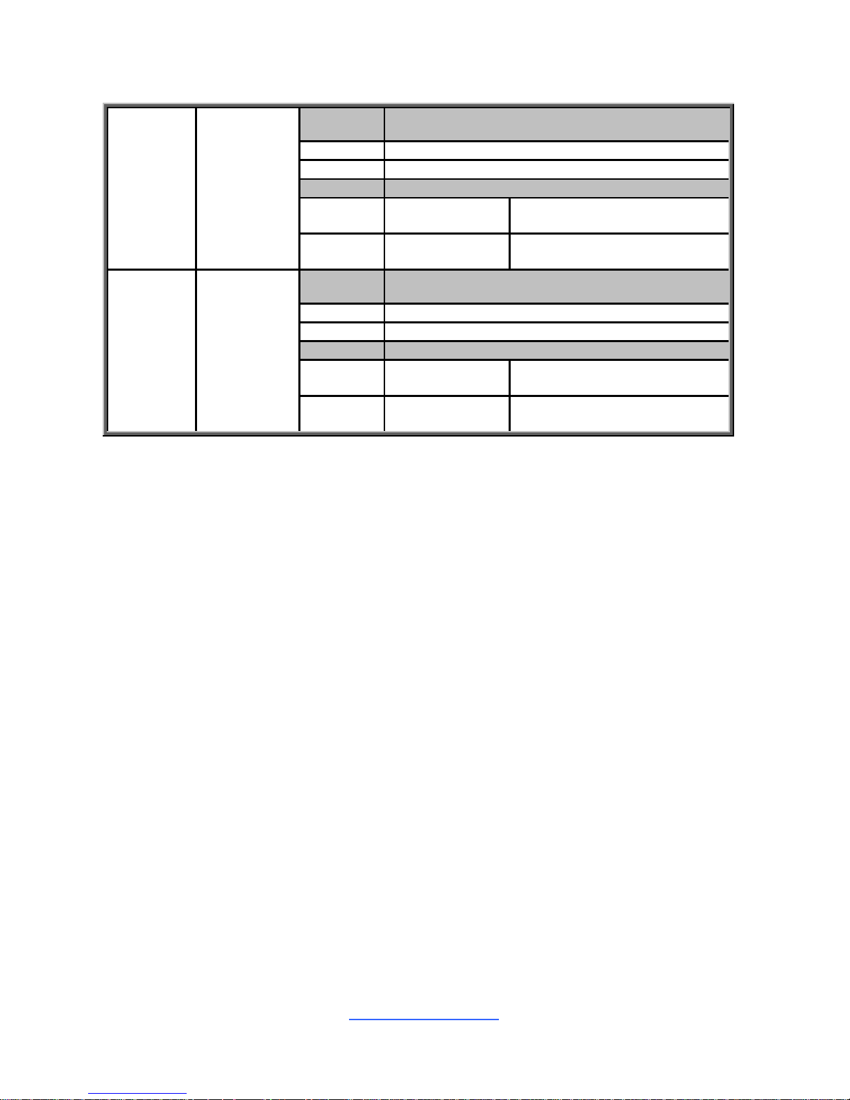
30
LED9
CPU1
PWOK LED
Pin Signal
+ + 3V
- GND
State Description
OFF OFF
The LED shuts off when the
power of CPU1 is abnormal.
ON Green
The LED lights up when the
power of CPU1 is normally.
LED10
PSU Alert
LED
Pin Signal
+ + VCC3_AUX
- GND
State Description
OFF OFF
The LED shuts off when the
PSU is normal.
ON Green
The LED lights up when the
PSU is abnormally.
 Loading...