

TYAN S7050 User Manual

S7050
Version 1.0c
Copyright
Copyright © MiTAC Computer Corporation, 2011. All rights reserved. No part of
this manual may be reproduced or translated without prior written consent from
MiTAC Computer Corp.
Trademark
All registered and unregistered trademarks and company names contained in
this manual are property of their respective owners including, but not limited to
the following.
TYAN® is a trademark of MiTAC Computer Corporation
Intel
®
is a trademark of Intel® Corporation.
AMI
®
, AMIBIOS® and combinations thereof are trademarks of AMI Technologies.
Microsoft
®
, Windows® are trademarks of Microsoft Corporation.
Aspeed
®
is a trademark of Aspeed Technology Inc.
Notice
Information contained in this document is furnished by MiTAC Computer
Corporation and has been reviewed for accuracy and reliability prior to printing.
MiTAC assumes no liability whatsoever, and disclaims any express or implied
warranty, relating to sale and/or use of TYAN
®
products including liability or
warranties relating to fitness for a particular purpose or merchantability. MiTAC
retains the right to make changes to product descriptions and/or specifications
at any time, without notice. In no event will MiTAC be held liable for any direct
or indirect, incidental or consequential damage, loss of use, loss of data or other
malady resulting from errors or inaccuracies of information contained in this
document.

http://www.TYAN.com
2
About this guide
This user guide contains the information you need when installing and configuring
the motherboard.
How this guide is organized
This guide contains the following parts:
Chapter1: Instruction
This chapter describes the features of the motherboard and the new technology it
supports.
Chapter2: Board Installation
This chapter lists the hardware setup procedures that you need to abide by when
installing system components. It includes description of the jumpers and connectors
on the motherboard.
Chapter3: BIOS Setup
This chapter tells how to change system settings through the BIOS setup menu.
Detailed descriptions of the BIOS parameters are also provided.
Chapter4: Diagnostics
This chapter introduces some BIOS codes and technical terms to provide better
service for the customers.

http://www.TYAN.com
3
Contents
Before you begin… ..............................................................................4
1.1 - Congratulations .............................................................................................5
1.2 - Hardware Specifications................................................................................ 5
1.3 - Software Specifications ............................................................................... 16
1.4 - AST2300 User Guide .................................................................................. 16
Chapter 2: Board Installation ............................................................17
2.1 - Board Image................................................................................................ 18
2.2 - Block Diagram .............................................................................................19
2.3 - Board Parts, Jumpers and Connectors........................................................ 20
2.4 - Installing the Processor ............................................................................... 38
2.5 - Installing the Heatsink ................................................................................. 41
2.6 - Thermal Interface Material........................................................................... 42
2.7 - Tips on Installing Motherboard in Chassis................................................... 43
2.8 - Installing the Memory .................................................................................. 45
2.9 - Attaching Drive Cables ................................................................................ 50
2.10 - Installing Add-In Cards .............................................................................. 51
2.11 - Connecting External Devices .................................................................... 52
2.12- Installing the Power Supply ........................................................................54
2.13 - Finishing Up .............................................................................................. 55
Chapter 3: BIOS Setup....................................................................... 56
3.1 - About the BIOS............................................................................................ 56
3.2 - Setup Basics ............................................................................................... 56
3.3 - Getting Help ................................................................................................ 57
3.4 - In Case of Problems .................................................................................... 57
3.5 - BIOS Main Menu ......................................................................................... 58
3.6 - BIOS Advanced Menu ................................................................................. 60
3.7 - Chipset Menu .............................................................................................. 81
3.8 - Boot Configuration....................................................................................... 95
3.9 - Security Menu.............................................................................................. 96
3.10 - Server Mgmt Menu .................................................................................... 97
3.11 - Save & Exit Menu.................................................................................... 100
Chapter 4: Diagnostics ....................................................................102
4.1 - Flash Utility................................................................................................ 102
4.2 AMIBIOS Post Code (Aptio) ...................................................................... 103
Glossary............................................................................................ 116
Technical Support............................................................................ 122

http://www.TYAN.com
4
Before you begin…
Check the box contents!
The retail motherboard package should contain the following:
Item Name P/N Number Description
1x S7050
Motherboard
/
N/A
6x Serial ATA
Cable
422736300010
TF-CABLE
ASSY;SBU,SATA500MM,S2865
1x I/O
shielding
340T44200001
TF-I/O SHIELDING
ASSY;SBU,S7050
1x S7050 User’s
manual
5615T4420001
TF-MANUAL;SBU,V1.0,USER
MANUAL, D2149-100,S7050
1x S7050 Quick
reference guide
5618T4420001
TF-SINGLE
PAGE;SBU,V1.00,QUICK
REFERENCE, D2150100,S7050
1x TYAN
®
Driver
CD
5651T4390001
TF-SOFTWARE;SBU,TYAN
Driver CD for Intel C600
series Platform V1.1,S7056
If any of these items are missing, please contact your vendor/dealer for
replacement before continuing with the installation process.
http://www.TYAN.com
5
Chapter 1: Instruction
1.1 - Congratulations
You have purchased the powerful TYAN
®
S7050 motherboard, based on the
Intel
®
Patsburg-A (PCH), ASPEED AST2300, NUVOTON Super I/O NCT5577D
chipsets. The S7050 is designed to support dual Intel
®
Xeon E5-2600 Series
(LGA2011) Series Processors and up to 128GB of 800, 1066, 1333 and
1600MHz DDR3 memory modules. Leveraging advanced technology from Intel®,
the S7050 is capable of offering scalable 32 and 64-bit computing, highbandwidth memory design, and lightning-fast PCI-E bus implementation.
The S7050 not only empowers you in today’s demanding IT environment but also
offers a smooth path for future application upgradeability. All of these rich feature
sets provides the S7050 with the power and flexibility to meet demanding
requirements for today’s IT environments.
The TYAN S7050 series is designed around several different configurations which
are detailed in the following 1.2 Hardware Specification section:
1.2 - Hardware Specifications
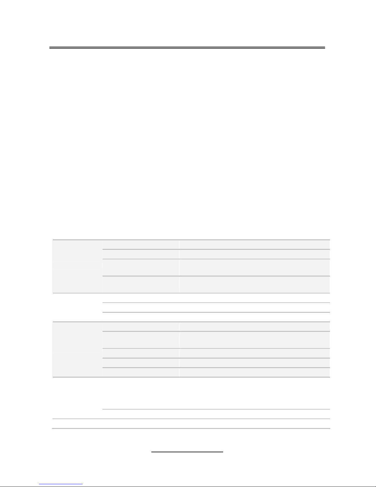
TYAN S7050 (S7050A2NRF)
Supported CPU Series Intel Xeon Processor E5-2600 Series
Socket Type / Q'ty LGA2011 / (2)
Thermal Design Power
(TDP) wattage
150W
Processor
System Bus
Up to 8.0/ 7.2/ 6.4 GT/s with Intel QuickPath
Interconnect (QPI) support
PCH Intel C602
Super I/O Nuvoton 5577D
Chipset
PCI-E Switch Pericom PI3PCIE3412
Supported DIMM Qty (8)+(8) DIMM slots
DIMM Type / Speed
DDR3/DDR3L 800 / 1066 / 1333 / 1600 RDIMM,
UDIMM / LRDIMM
Capacity up to 128GB UDIMM
Memory channel 4 Channels per CPU
Memory
Memory voltage 1.5V or 1.35V
PCI-E
(1) PCI-E x4 slot ( x4 link) / (1) PCI-E x16 slot ( x16
link or x8 link) / (1) PCI-E x8 slot ( x8 link or x0 link)
/ (1) PCI-E x16 slot ( x16 link or x8 link) / (1) PCI-E
x8 slot ( x8 link or x0 link)
Expansion
Slots
PCI (1) PCI 32-bit slot

http://www.TYAN.com
6
Port Q'ty (2) GbE ports
LAN
Controller Intel 82574L
Connector (6) SATA
Controller Intel C602
Speed (2) 6.0 Gb/s (blue color), (4) 3.0 Gb/s (black color)
SATA
RAID RAID 0/1/10/5 (Intel Matrix RAID)
Connector (4) SATA connector
Controller Intel C602
Speed 3.0 Gb/s
Storage
SATA
From
(SCU)
RAID RAID 0/1/10 (Intel Matrix RAID)
Chipset Realtek ALC262
Audio
Feature High Definition Audio
USB
(7) USB2.0 ports (4 at rear, 2 at front, 1 type A
onboard) / (2) USB3.0 ports (at rear)
COM
(1) DB-9 COM Connector (at rear, COM1) + (1)
Header (COM2)
Audio LINE_IN, LINE_OUT, MIC_IN connectors
RJ-45 (2) GbE ports
Firewire (2) 2x5-pin headers
Power
SSI 24-pin + 8-pin + 8-pin power connectors / (1) 4
PIN power connector for PCI-E
Front Panel (1) 2x12-pin SSI front panel header
PSMI (1) 1x5-pin header
Input /Output
IPMB (1) 1x4-pin header
Chipset Winbond W83795G
Voltage
Monitors voltage for CPU, memory, chipset &
power supply
Fan Total (7) 4-pin headers
System
Monitoring
Temperature
Monitors temperature for CPU & system
environment
Brand / ROM size AMI / 8MB
BIOS
Feature
Plug and Play (PnP) /PCI2.3 /WfM2.0 /SMBIOS2.3
/PXE boot / ACPI 2.0 power management /Power
on mode after power recovery / User-configurable
H/W monitoring / Auto-configurable of hard disk
types
Form Factor SSI EEB
Physical
Dimension
Board Dimension 12"x13" (305x330mm)
Operating
System
OS supported list Please refer to our OS supported list.
FCC (DoC) Class B
Regulation
CE (DoC) Yes
http://www.TYAN.com
7
Operating Temp. 10° C ~ 35° C (50° F~ 95° F)
Non-operating Temp. - 40° C ~ 70° C (-40° F ~ 158° F)
Operating
Environment
In/Non-operating
Humidity
90%, non-condensing at 35° C
RoHS RoHS 6/6 Compliant Yes
Motherboard (1) S7050 Motherboard
Manual (1) User's manual / (1) Quick Ref. Guide
Installation CD (1) TYAN installation CD
I/O Shield (1) I/O Shield
Package
Contains
Cable SATA (6) SATA signal cables
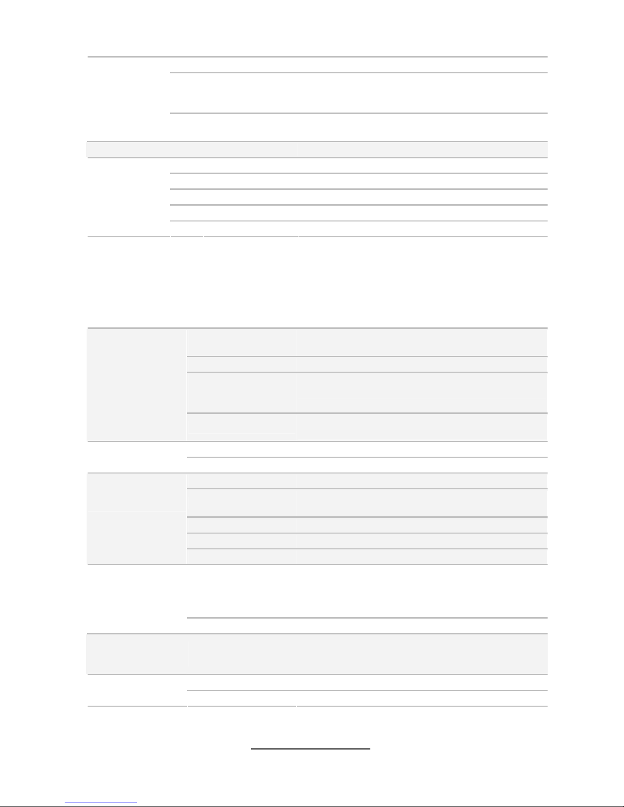
TYAN S7050 (S7050GM4NR) Server SKU
Supported CPU
Series
Intel Xeon Processor E5-2600 Series
Socket Type / Q'ty LGA2011 / (2)
Thermal Design
Power (TDP)
wattage
130W
Processor
System Bus
Up to 8.0/ 7.2/ 6.4 GT/s with Intel QuickPath
Interconnect (QPI) support
PCH Intel C602
Chipset
PCI-E Switch Pericom PI3PCIE3412
Supported DIMM Qty (8)+(8) DIMM slots
DIMM Type / Speed
DDR3/DDR3L 800 / 1066 / 1333 / 1600 RDIMM,
UDIMM / LRDIMM
Capacity up to 128GB UDIMM
Memory channel 4 Channels per CPU
Memory
Memory voltage 1.5V or 1.35V
PCI-E
(1) PCI-E x4 slot ( x4 link,) / (1) PCI-E x16 slot ( x16
link or x8 link,) / (1) PCI-E x8 slot ( x8 link or x0
link,) / (1) PCI-E x16 slot ( x16 link or x8 link,) / (1)
PCI-E x8 slot ( x8 link or x0 link,)
Expansion Slots
PCI (1) PCI 32-bit slot
Recommended
Barebone /
Chassis
Mechanical
Compliant
KFT48 / KGN70M1 / KGTN70M1
Port Q'ty (4) GbE ports
LAN
Controller Intel 82574L / Intel I350AM2
http://www.TYAN.com
8
Connector (6) SATA
Controller Intel C602
Speed (2) 6.0 Gb/s (blue color), (4) 3.0 Gb/s (black color)
SATA
RAID RAID 0/1/10/5 (Intel Matrix RAID)
Connector (4) SATA connector
Controller Intel C602
Speed 3.0 Gb/s
Storage
SATA
From
(SCU)
RAID RAID 0/1/10 (Intel Matrix RAID)
USB
(7) USB2.0 ports (4 at rear, 2 at front, 1 type A
onboard)
COM
(1) DB-9 COM Connector (at rear, COM1) + (1)
Header (COM2)
VGA (1) D-Sub 15-pin VGA port
RJ-45 (4) GbE ports
Power
SSI 24-pin + 8-pin + 8-pin power connectors / (1) 4
PIN power connector for PCI-E
Front Panel (1) 2x12-pin SSI front panel header
PSMI (1) 1x5-pin header
IPMB (1) 1x4-pin header
Input /Output
SATA (4) SATA-II and (2) SATA-III connectors
Chipset Winbond W83795G
Voltage
Monitors voltage for CPU, memory, chipset &
power supply
Fan Total (7) 4-pin headers
System Monitoring
Temperature
Monitors temperature for CPU & system
environment
Onboard Chipset Onboard Aspeed AST2300
AST2300 IPMI
Feature
IPMI 2.0 compliant baseboard management
controller (BMC) / Supports storage over IP and
remote platform-flash / USB 2.0 virtual hub / BIOS
update
Server
Management
AST2300 iKVM
Feature
24-bit high quality video compression / Dual 10/100
Mb/s MAC interfaces / 10/100 Mb/s MAC interface
Brand / ROM size AMI / 8MB
BIOS
Feature
Plug and Play (PnP) /PCI2.3 /WfM2.0 /SMBIOS2.3
/PXE boot / ACPI 2.0 power management /Power
on mode after power recovery / User-configurable
H/W monitoring / Auto-configurable of hard disk
types
Form Factor SSI EEB
Physical
Dimension
Board Dimension 12"x13" (305x330mm)
Operating System OS supported list Please refer to our OS supported list.
FCC (DoC) Class B
Regulation
CE (DoC) Yes
http://www.TYAN.com
9
Operating Temp. 10° C ~ 35° C (50° F~ 95° F)
Non-operating
Temp.
- 40° C ~ 70° C (-40° F ~ 158° F)
Operating
Environment
In/Non-operating
Humidity
90%, non-condensing at 35° C
RoHS RoHS 6/6 Compliant Yes
Motherboard (1) S7050 Motherboard
Manual (1) User's manual / (1) Quick Ref. Guide
Installation CD (1) TYAN installation CD
I/O Shield (1) I/O Shield
Package Contains
Cable SATA (6) SATA signal cables
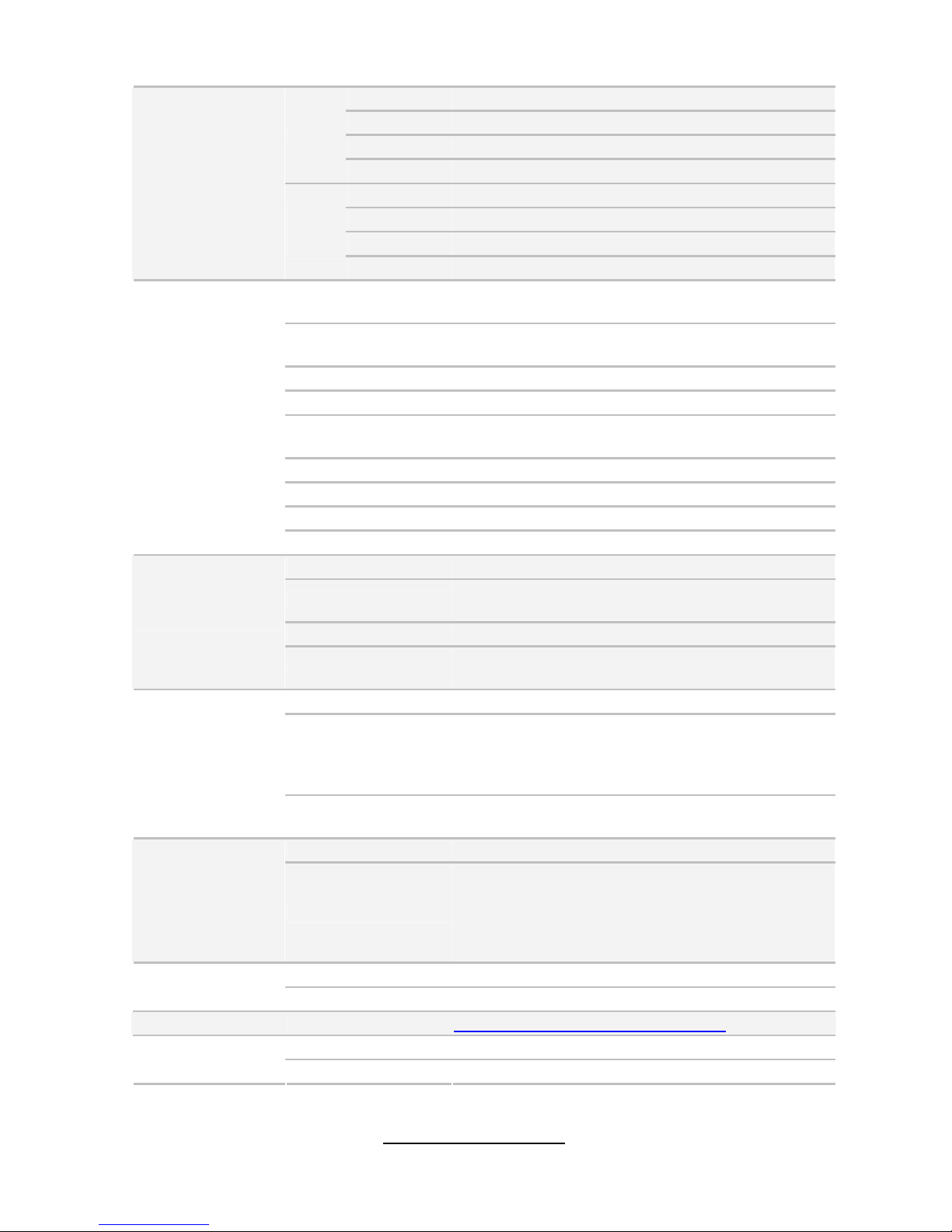
TYAN S7050 (S7050WGM4NR) Server SKU
Supported CPU
Series
Intel Xeon Processor E5-2600 Series
Socket Type / Q'ty LGA2011 / (2)
Thermal Design
Power (TDP)
wattage
130W
Processor
System Bus
Up to 8.0/ 7.2/ 6.4 GT/s with Intel QuickPath
Interconnect (QPI) support
PCH Intel C602 with upgrade ROM module
Chipset
PCI-E Switch Pericom PI3PCIE3412
Supported DIMM
Qty
(8)+(8) DIMM slots
DIMM Type / Speed
DDR3/DDR3L 800 / 1066 / 1333 / 1600 RDIMM, UDIMM
/ LRDIMM
Capacity up to 128GB UDIMM
Memory channel 4 Channels per CPU
Memory
Memory voltage 1.5V or 1.35V
PCI-E
(1) PCI-E x4 slot ( x4 link,) / (1) PCI-E x16 slot ( x16 link
or x8 link,) / (1) PCI-E x8 slot ( x8 link or x0 link,) / (1)
PCI-E x16 slot ( x16 link or x8 link,) / (1) PCI-E x8 slot
( x8 link or x0 link,)
Expansion
Slots
PCI (1) PCI 32-bit slot
Recommended
Barebone /
Chassis
Mechanical
Compliant
KFT48 / KGN70M1 / KGTN70M1
Port Q'ty (4) GbE ports
LAN
Controller Intel 82574L / Intel I350AM2
Connector (8) SAS connector
Controller Intel C602 with TRK-5 upgrade ROM module
Storage SAS
Speed 3.0 Gb/s
http://www.TYAN.com
10
RAID RAID 0/1/10
Connector (6) SATA
Controller Intel C602
Speed (2) 6.0 Gb/s (blue color), (4) 3.0 Gb/s (black color)
SATA
RAID RAID 0/1/10/5 (Intel Matrix RAID)
Graphic Connector type D-Sub 15-pin
USB (7) USB2.0 ports (4 at rear, 2 at front, 1 type A onboard)
COM
(1) DB-9 COM Connector (at rear, COM1) + (1) Header
(COM2)
SAS (8) SAS connectors
VGA (1) D-Sub 15-pin VGA port
RJ-45 (4) GbE ports
Power
SSI 24-pin + 8-pin + 8-pin power connectors / (1) 4 PIN
power connector for PCI-E
Front Panel (1) 2x12-pin SSI front panel header
PSMI (1) 1x5-pin header
IPMB (1) 1x4-pin header
Input /Output
SATA (4) SATA-II and (2) SATA-III connectors
Chipset Winbond W83795G
Voltage
Monitors voltage for CPU, memory, chipset & power
supply
Fan Total (7) 4-pin headers
System
Monitoring
Temperature Monitors temperature for CPU & system environment
Onboard Chipset Onboard Aspeed AST2300
AST2300 IPMI
Feature
IPMI 2.0 compliant baseboard management controller
(BMC) / Supports storage over IP and remote platformflash / USB 2.0 virtual hub / BIOS update
Server
Management
AST2300 iKVM
Feature
24-bit high quality video compression / Dual 10/100 Mb/s
MAC interfaces / 10/100 Mb/s MAC interface
Brand / ROM size AMI / 8MB
BIOS
Feature
Plug and Play (PnP) /PCI2.3 /WfM2.0 /SMBIOS2.3 /PXE
boot / ACPI 2.0 power management /Power on mode
after power recovery / User-configurable H/W monitoring
/ Auto-configurable of hard disk types
Form Factor SSI EEB
Physical
Dimension
Board Dimension 12"x13" (305x330mm)
Operating
System
OS supported list Please refer to our OS supported list.
FCC (DoC) Class B
Regulation
CE (DoC) Yes
Operating Temp. 10° C ~ 35° C (50° F~ 95° F)
Operating
Environment
Non-operating
Temp.
- 40° C ~ 70° C (-40° F ~ 158° F)
http://www.TYAN.com
11
In/Non-operating
Humidity
90%, non-condensing at 35° C
RoHS RoHS 6/6 Compliant Yes
Motherboard (1) S7050 Motherboard
Manual (1) User's manual / (1) Quick Ref. Guide
Installation CD (1) TYAN installation CD
I/O Shield (1) I/O Shield
Package
Contains
Cable SATA (6) SATA signal cables
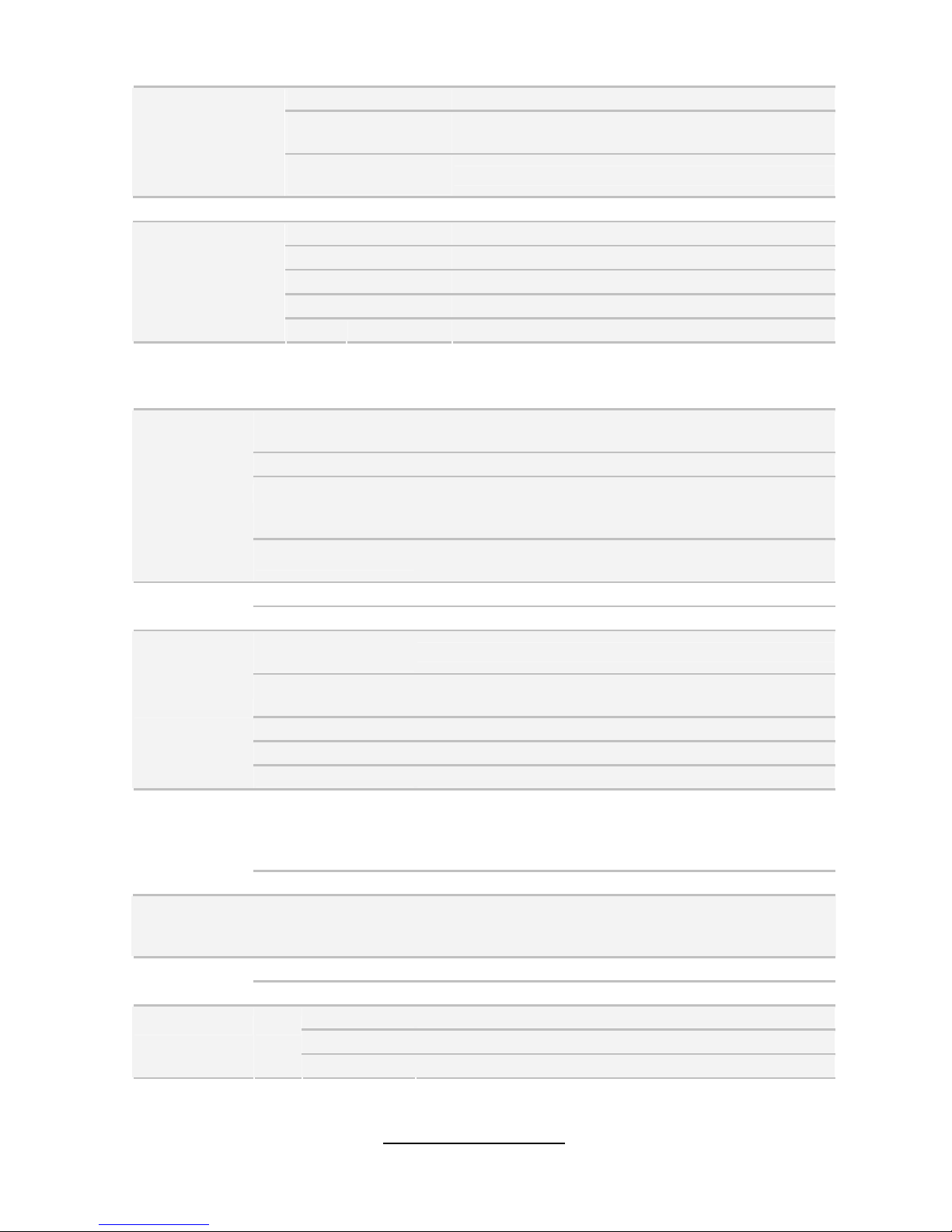
TYAN S7050 (S7050GM2NR[BTO])
Supported CPU
Series
Intel Xeon Processor E5-2600 Series
Socket Type / Q'ty LGA2011 / (2)
Thermal Design
Power (TDP)
wattage
130W
Processor
System Bus
Up to 8.0/ 7.2/ 6.4 GT/s with Intel QuickPath
Interconnect (QPI) support
PCH Intel C602
Chipset
PCI-E Switch Pericom PI3PCIE3412
Supported DIMM
Qty
(8)+(8) DIMM slots
DIMM Type / Speed
DDR3/DDR3L 800 / 1066 / 1333 / 1600 RDIMM,
UDIMM / LRDIMM
Capacity up to 128GB UDIMM
Memory channel 4 Channels per CPU
Memory
Memory voltage 1.5V or 1.35V
PCI-E
(1) PCI-E x4 slot ( x4 link,) / (1) PCI-E x16 slot ( x16
link or x8 link,) / (1) PCI-E x8 slot ( x8 link or x0
link,) / (1) PCI-E x16 slot ( x16 link or x8 link,) / (1)
PCI-E x8 slot ( x8 link or x0 link,)
Expansion Slots
PCI (1) PCI 32-bit slot
Recommended
Barebone /
Chassis
Mechanical
Compliant
KFT48 / KGN70M1 / KGTN70M1
Port Q'ty (2) GbE ports
LAN
Controller Intel 82574L
Connector (6) SATA
Controller Intel C602
Speed (2) 6.0 Gb/s (blue color), (4) 3.0 Gb/s (black color)
Storage
SATA
RAID RAID 0/1/10/5 (Intel Matrix RAID)

http://www.TYAN.com
12
Connector (4) SATA connector
Controller Intel C602
Speed 3.0 Gb/s
SATA
From
(SCU)
RAID RAID 0/1/10 (Intel Matrix RAID)
USB
(7) USB2.0 ports (4 at rear, 2 at front, 1 type A
onboard)
COM
(1) DB-9 COM Connector (at rear, COM1) + (1)
Header (COM2)
VGA (1) D-Sub 15-pin VGA port
RJ-45 (2) GbE ports
Power
SSI 24-pin + 8-pin + 8-pin power connectors / (1) 4
PIN power connector for PCI-E
Front Panel (1) 2x12-pin SSI front panel header
PSMI (1) 1x5-pin header
IPMB (1) 1x4-pin header
Input /Output
SATA (4) SATA-II and (2) SATA-III connectors
Chipset Winbond W83795G
Voltage
Monitors voltage for CPU, memory, chipset & power
supply
Fan Total (7) 4-pin headers
System
Monitoring
Temperature
Monitors temperature for CPU & system
environment
Onboard Chipset Onboard Aspeed AST2300
AST2300 IPMI
Feature
IPMI 2.0 compliant baseboard management
controller (BMC) / Supports storage over IP and
remote platform-flash / USB 2.0 virtual hub / BIOS
update
Server
Management
AST2300 iKVM
Feature
24-bit high quality video compression / One 10/100
Mb/s MAC interfaces / 10/100 Mb/s MAC interface
Brand / ROM size AMI / 8MB
BIOS
Feature
Plug and Play (PnP) /PCI2.3 /WfM2.0 /SMBIOS2.3
/PXE boot / ACPI 2.0 power management /Power
on mode after power recovery / User-configurable
H/W monitoring / Auto-configurable of hard disk
types
Form Factor SSI EEB
Physical
Dimension
Board Dimension 12"x13" (305x330mm)
Operating System OS supported list Please refer to our OS supported list.
FCC (DoC) Class B
Regulation
CE (DoC) Yes
Operating Temp. 10° C ~ 35° C (50° F~ 95° F)
Non-operating
Temp.
- 40° C ~ 70° C (-40° F ~ 158° F)
Operating
Environment
In/Non-operating 90%, non-condensing at 35° C

http://www.TYAN.com
13
Humidity
RoHS
RoHS 6/6
Compliant
Yes
Motherboard (1) S7050 Motherboard
Manual (1) User's manual / (1) Quick Ref. Guide
Installation CD (1) TYAN installation CD
I/O Shield (1) I/O Shield
Package Contains
Cable SATA (6) SATA signal cables
TYAN S7050 (S7050WGM2NR[BTO])
Supported CPU
Series
Intel Xeon Processor E5-2600 Series
Socket Type / Q'ty LGA2011 / (2)
Thermal Design
Power (TDP)
wattage
150W
Processor
System Bus
Up to 8.0/ 7.2/ 6.4 GT/s with Intel QuickPath
Interconnect (QPI) support
PCH Intel C602 with upgrade ROM module
Chipset
PCI-E Switch Pericom PI3PCIE3412
Supported DIMM
Qty
(8)+(8) DIMM slots
DIMM Type / Speed
DDR3/DDR3L 800 / 1066 / 1333 / 1600 RDIMM,
800 / 1066 / 1333 UDIMM / LRDIMM / Support
DDR3 Unbuffered and Register ECC
Capacity up to 128GB UDIMM
Memory channel 4 Channels per CPU
Memory
Memory voltage 1.5V or 1.35V
PCI-E
(1) PCI-E x4 slot ( x4 link,) / (1) PCI-E x16 slot
( x16 link or x8 link,) / (1) PCI-E x8 slot ( x8 link or
x0 link,) / (1) PCI-E x16 slot ( x16 link or x8 link, ) /
(1) PCI-E x8 slot ( x8 link or x0 link,)
Expansion Slots
PCI (1) PCI 32-bit slot
Recommended
Barebone /
Chassis
Mechanical
Compliant
KFT48 / KGN70M1 / KGTN70M1
Port Q'ty (2) GbE ports
LAN
Controller Intel 82574L
Connector (8) SAS connector
Controller Intel C602 with TRK-5 upgrade ROM module
Speed 3.0 Gb/s
Storage
SAS
RAID RAID 0/1/10
http://www.TYAN.com
14
Connector (6) SATA
Controller Intel C602
Speed (2) 6.0 Gb/s (blue color), (4) 3.0 Gb/s (black color)
SATA
RAID RAID 0/1/10/5 (Intel Matrix RAID)
Graphic Connector type D-Sub 15-pin
USB
(7) USB2.0 ports (4 at rear, 2 at front, 1 type A
onboard)
COM
(1) DB-9 COM Connector (at rear, COM1) + (1)
Header (COM2)
SAS (8) SAS connectors
VGA (1) D-Sub 15-pin VGA port
RJ-45 (2) GbE ports
Power
SSI 24-pin + 8-pin + 8-pin power connectors / (1) 4
PIN power connector for PCI-E
Front Panel (1) 2x12-pin SSI front panel header
PSMI (1) 1x5-pin header
IPMB (1) 1x4-pin header
Input /Output
SATA (4) SATA-II and (2) SATA-III connectors
Chipset Winbond W83795G
Voltage
Monitors voltage for CPU, memory, chipset &
power supply
Fan Total (7) 4-pin headers
System
Monitoring
Temperature
Monitors temperature for CPU & system
environment
Onboard Chipset Onboard Aspeed AST2300
AST2300 IPMI
Feature
IPMI 2.0 compliant baseboard management
controller (BMC) / Supports storage over IP and
remote platform-flash / USB 2.0 virtual hub / BIOS
update
Server
Management
AST2300 iKVM
Feature
24-bit high quality video compression / Dual
10/100 Mb/s MAC interfaces / 10/100 Mb/s MAC
interface
Brand / ROM size AMI / 8MB
BIOS
Feature
Plug and Play (PnP) /PCI2.3 /WfM2.0 /SMBIOS2.3
/PXE boot / ACPI 2.0 power management /Power
on mode after power recovery / User-configurable
H/W monitoring / Auto-configurable of hard disk
types
Form Factor SSI EEB
Physical
Dimension
Board Dimension 12"x13" (305x330mm)
Operating System OS supported list Please refer to our OS supported list.
FCC (DoC) Class B
CE (DoC) Yes
Regulation

http://www.TYAN.com
15
Operating Temp. 10° C ~ 35° C (50° F~ 95° F)
Non-operating
Temp.
- 40° C ~ 70° C (-40° F ~ 158° F)
Operating
Environment
In/Non-operating
Humidity
90%, non-condensing at 35° C
RoHS RoHS 6/6 Compliant Yes
Motherboard (1) S7050 Motherboard
Manual (1) User's manual / (1) Quick Ref. Guide
Installation CD (1) TYAN installation CD
I/O Shield (1) I/O Shield
Package Contains
Cable SATA (6) SATA signal cables
http://www.TYAN.com
16
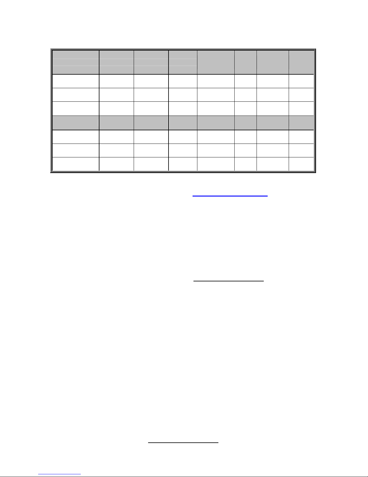
S7050 SKU Comparison Table
Model PCH 1G LAN IPMI
Front USB
HEADER
USB
Type A
1 x 4 fan
connector
ID
switch
S7050A2NRF Patsburg-A 2 NO 1 1 7 NO
S7050GM4NR Patsburg-A 4 AST2300 1 1 7 YES
S7050WGM4NR
Patsburg+
ROM-5
4 AST2300 1 1 7 YES
Model BMC
X16/x8/x4/
PCI
SAS
Raid
SATA
3Gb/s
1394
USB
3.0
Audio
S7050A2NRF NO 2/2/1/1 NO 4 Yes 2 Yes
S7050GM4NR Yes 2/2/1/1 NO 4 NO 0 NO
S7050WGM4NR Yes 2/2/1/1 0/1/10 4 NO 0 NO
Remember to visit TYAN
®
’s Website at http://www.TYAN.com. There you
can find information on all of TYAN
®
’s products with FAQs, online manuals
and BIOS upgrades and more.
1.3 - Software Specifications
For OS (operation system) support, please check the TYAN® website for the
latest information.
1.4 - AST2300 User Guide
Remember to visit TYAN®’s Website at http://www.TYAN.com for AST2300
user guide.
http://www.TYAN.com
17
Chapter 2: Board Installation
You are now ready to install your motherboard.
How to install our products right… the first time
The first thing you should do is reading this user’s manual. It contains important
information that will make configuration and setup much easier. Here are some
precautions you should take when installing your motherboard:
(1) Ground yourself properly before removing your motherboard from the
antistatic bag. Unplug the power from your computer power supply and
then touch a safely grounded object to release static charge (i.e. power
supply case). For the safest conditions, TYAN® recommends wearing a
static safety wrist strap.
(2) Hold the motherboard by its edges and do not touch the bottom of the
board, or flex the board in any way.
(3) Avoid touching the motherboard components, IC chips, connectors,
memory modules, and leads.
(4) Place the motherboard on a grounded antistatic surface or on the antistatic
bag that the board was shipped in.
(5) Inspect the board for damage.
The following pages include details on how to install your motherboard into your
chassis, as well as installing the processor, memory, disk drives and cables.
Caution!
1. To avoid damaging the motherboard and associated
components, do not use torque force greater than
7kgf/cm (6.09 lb/in) on each mounting screw for
motherboard installation.
2. Do not apply power to the board if it has been
damaged.
http://www.TYAN.com
18
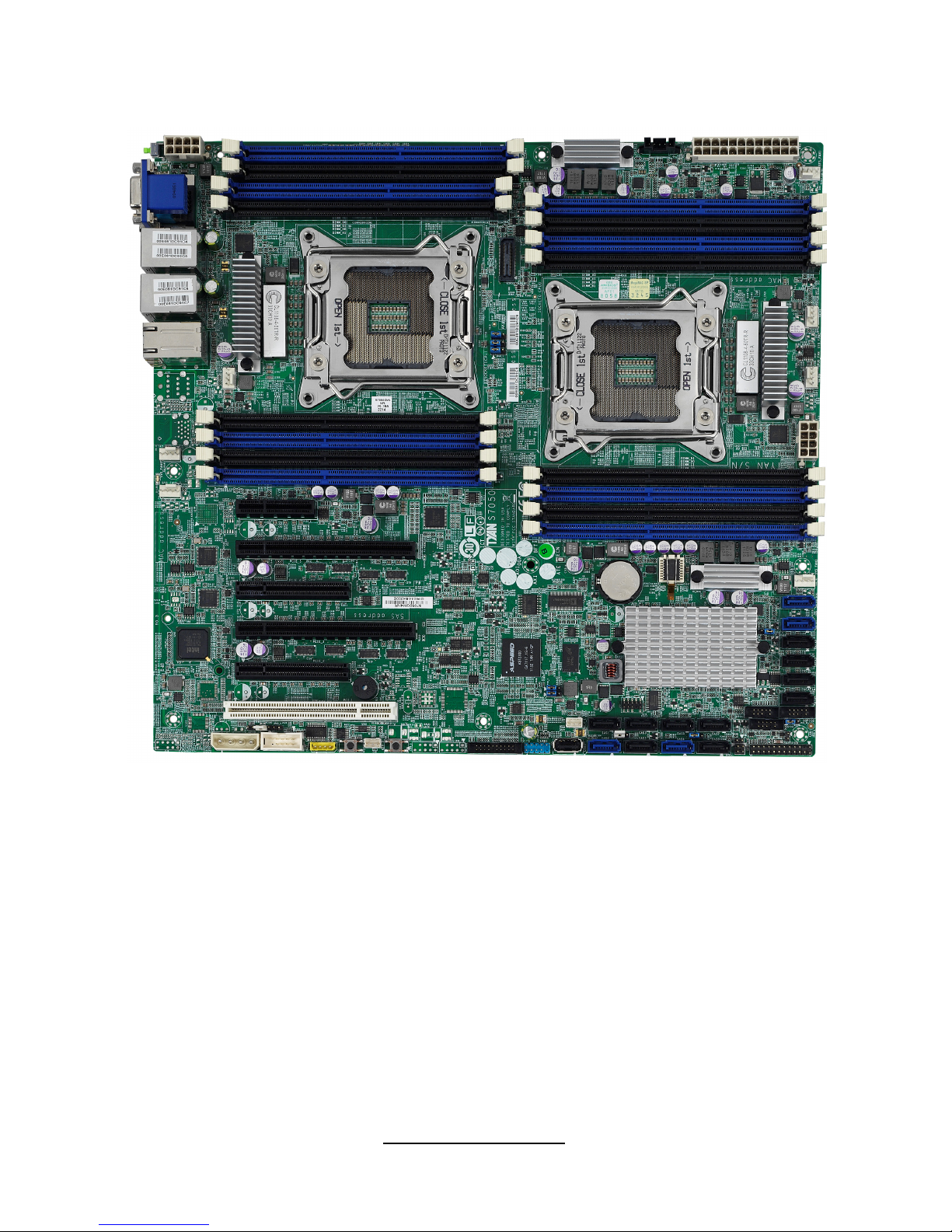
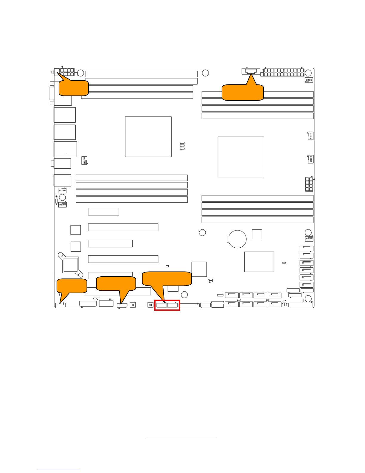
2.1 - Board Image
S7050
This diagram is representative of the latest motherboard revision available at the
time of publishing. The board you receive may not look exactly like the above
diagram.

http://www.TYAN.com
19
2.2 - Block Diagram
S7050
http://www.TYAN.com
20
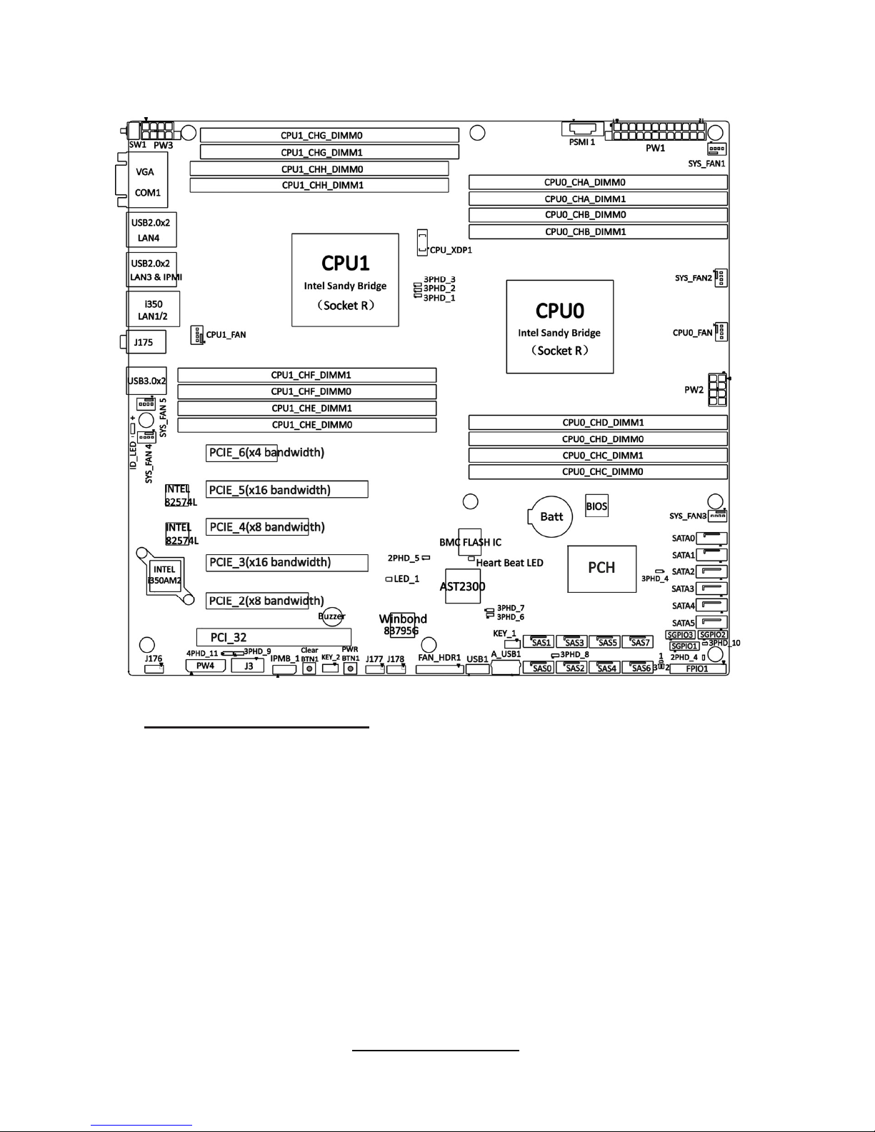
2.3 - Board Parts, Jumpers and Connectors
Important Notes to the User
• "▲" indicates the location of "Pin 1".
• The diagram is representative of the latest board revision available at the time of
publishing. The board you received may not look exactly like this diagram.

http://www.TYAN.com
21
Jumpers & Connectors
Jumper/Connector Function
SYS FAN1~5/CPU0~1FAN 4-pin Fan connector
FAN_HDR1 FAN Connector for Barebone
J3 COM2 Header
J175 Line-In Line-Out MIC
J176 Front Panel Audio
J177/ J178 1394 PIN HEADER
SW1 ID_LED Button 1
IPMB_1 IPMB Pin Header
PSMI 1 PSMI Connector
Clear BTN1 RTC reset button
FPIO_1 Front Panel Header
A_USB1 TYPE-A USB From PCH
USB1 Front USB Header
KEY1 Patsburg Upgrade ROM Header
2PHD_1 INTRUDER header
2PHD_2 I350_LAN0 LED Front Panel Pin
2PHD_3 I350_LAN1 LED Front Panel Pin
2PHD_4 ID LED Pin Header
2PHD_5 BMC RST header
3PHD_1 / 3PHD_2/3PHD_3 CPU XDP bypass Jump
3PHD_4 ME RECOVERY MODE Jump
3PHD_5 BIOS RECOVERY Jumper
3PHD_6 / 3PHD_7 COM Select
3PHD_8 BIOS Overwrite Jumper
3PHD_9
PCH Host SM_BUS header for ME
Debug
3PHD_10 DIMM 1.5V/1.35V Jumper
4PHD_11 MB BEEP Disable header
http://www.TYAN.com
22
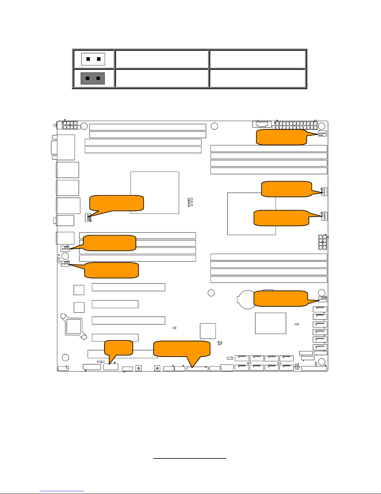
Jumper Legend
OPEN - Jumper OFF
Without jumper cover
CLOSED - Jumper ON
With jumper cover
Jumper Placement
SYS_FAN2
CPU0_FAN
SYS_FAN1
SYS_FAN5
CPU1_FAN
SYS_FAN3
SYS_FAN4
FAN_HDR1
J3
http://www.TYAN.com
23
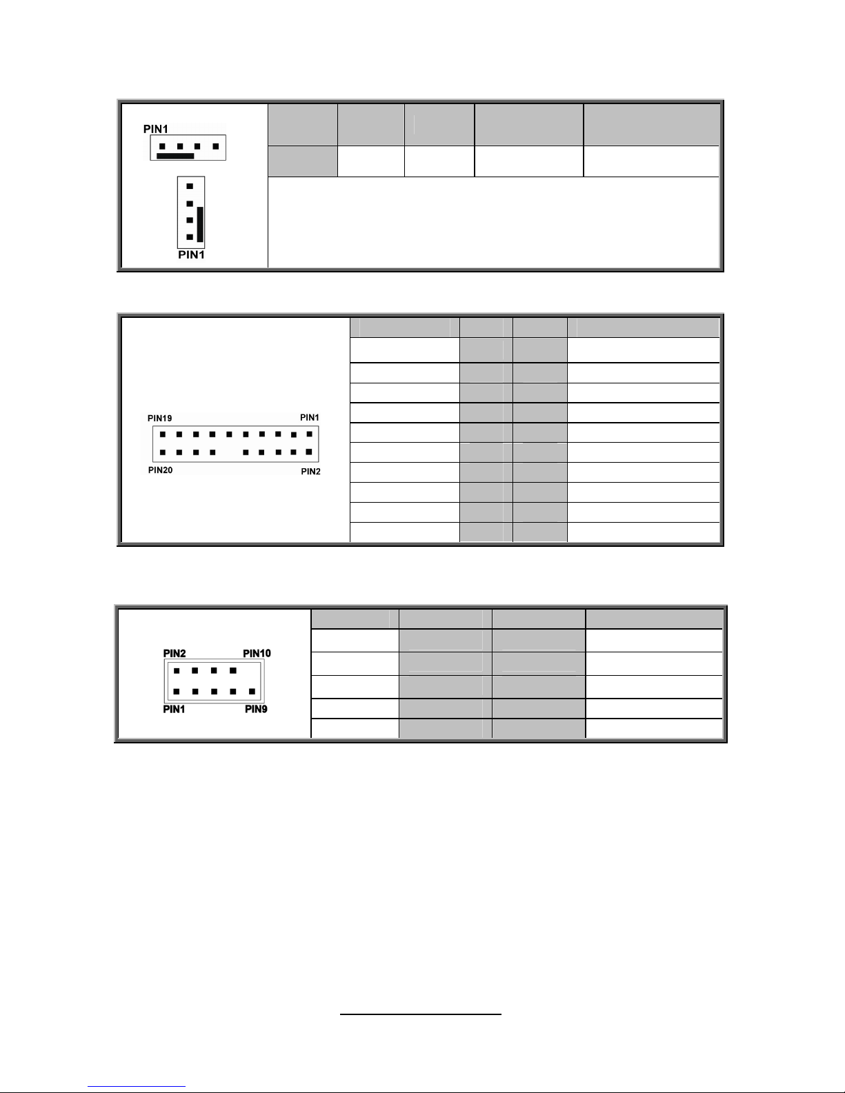
SYS FAN1~5/CPU0~1FAN : 4-Pin FAN Connector
Pin 1 2 3 4
Signal
GND P12V FAN_TACH FAN_PWM
NOTE:
Use this header to connect the cooling fan to your
motherboard to keep the system stable and reliable.
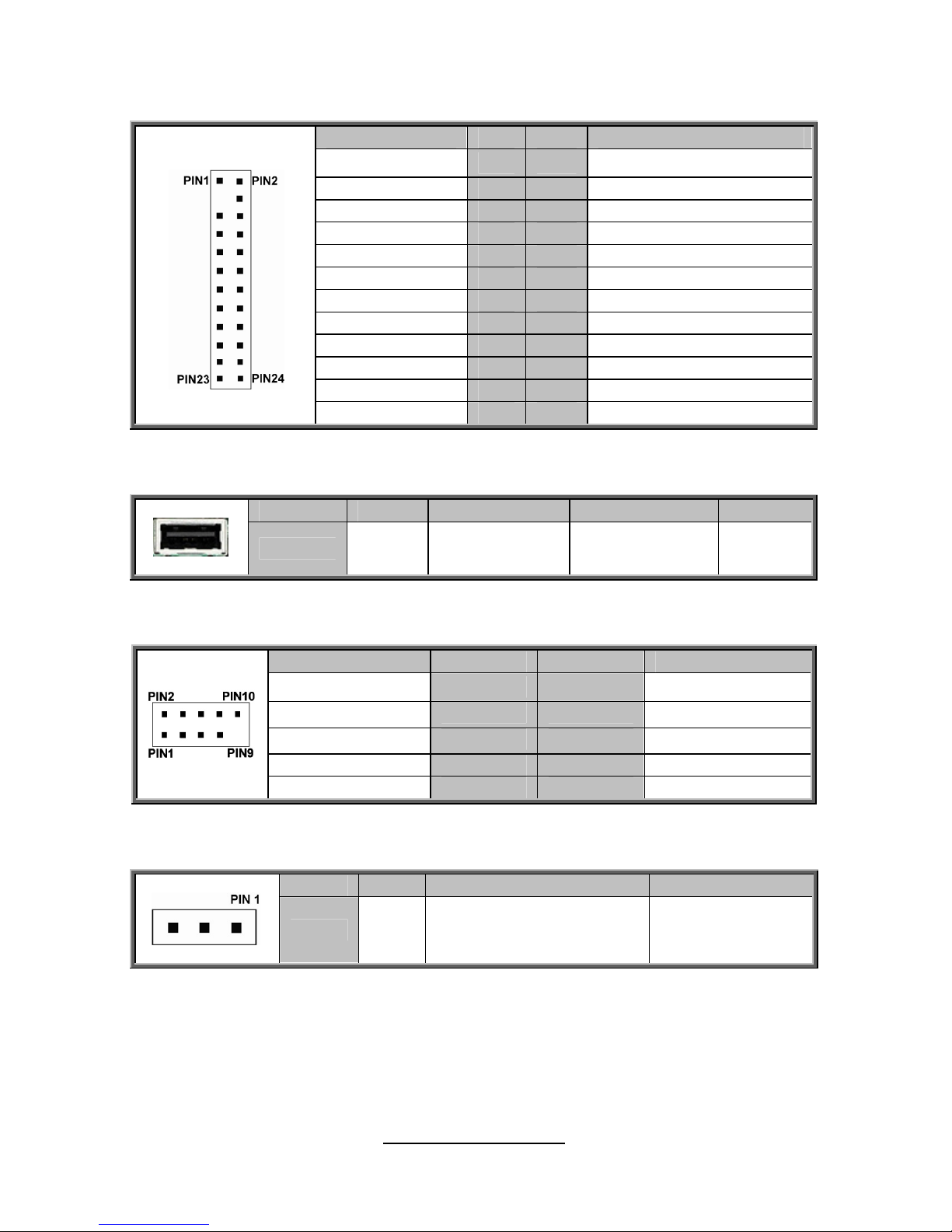
FAN_HDR1: FAN Connector for Barebone
Signal Pin Pin Signal
TACH1
1 2
TACH6
TACH2
3 4
TACH7
TACH3
5 6
TACH8
TACH4
7 8
TACH9
TACH5
9 10
TACH10
GND
11 12
KEY
PWM2
13 14
PWM1
TACH11
15 16
SDA
TACH12
17 18
SCL
NC
19 20
PWM3
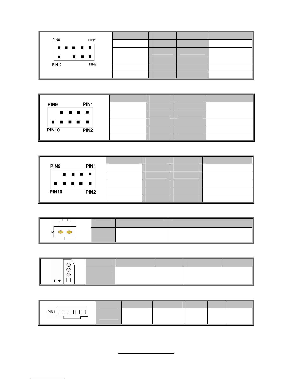
J3: COM2 Header
Signal Pin Pin Signal
DCD
1 2
DSR
RXD
3 4
RTS
TXD
5 6
CTS
DTR
7 8
RI
GND
9 10
KEY
http://www.TYAN.com
24
J176
PSMI 1
J177/J178
IPMB1
SW1
http://www.TYAN.com
25
J176: Front Panel Audio
Signal Pin Pin Signal
MIC2-L
1 2
GND
MIC2-R
3 4
FP_Present
LINE2-R
5 6
MIC2-JD
FPIO Sense
7 8
Key
LINE2-R
9 10
LINE2-JD
J177: 1394 PIN HEADER
Signal Pin Pin Signal
XTP_A_P_0
1 2
XTP_A_N_0
GND
3 4
GND
XTP_B_P_0
5 6
XTP_B_N_0
VCC
7 8
VCC
KEY
9 10
GND
J178: 1394 PIN HEADER
Signal Pin Pin Signal
XTP_A_P_1
1 2
XTP_A_N_1
GND
3 4
GND
XTP_B_P_1
5 6
XTP_B_N_1
VCC
7 8
VCC
KEY
9 10
GND
SW1: ID LED Switch Button
Pin 1 2
Signal
ID LED BTN ID LED GND
IPMB_1:
IPMB Pin Header
Pin 1 2 3 4
Signal
IPMB DATA GND IPMB CLK NC
PSMI1: PSMI Connector
Pin 1 2 3 4 5
Signal
SMB_CLK SMB_DAT
PSU
Alert#
GND
3.3V
Standby
http://www.TYAN.com
26
K
EY1 FPIO 1
A_USB1
USB1
http://www.TYAN.com
27
FPIO_1: Front Panel Header
Signal Pin Pin Signal
PWRLED+
1 2
FP Power (3.3V)
KEY
3 4
ID_LED+
PWRLED-(GND)
5 6
ID_LED-(GND)
HD_LED+
7 8
Fault LED1-
HD_LED-
9 10
Fault LED2-
Power Switch+
11 12
LAN1_ACTIVE_LED+
GND
13 14
LAN1_ACTIVE_LED-
Reset Switch+
15 16
SMB_DATA
GND
17 18
SMB_CLK
ID Switch+
19 20
INTRUSION#
GND
21 22
LAN2_ACTIVE_LED+
NMI Switch#
23 24
LAN2_ACTIVE_LED-
A_USB1:
Vertical TYPE-A USB From PCH
Pin 1 2 3 4
Signal
+5V USB DATA2- USB DATA2+ GND
USB1: Front USB Header
Signal Pin Pin Signal
USB 5V Power
1 2
USB 5V Power
USB DATA1-
3 4
USB DATA2-
USBDATA1+
5 6
USB DATA2+
GND
7 8
GND
KEY
9 10
NC
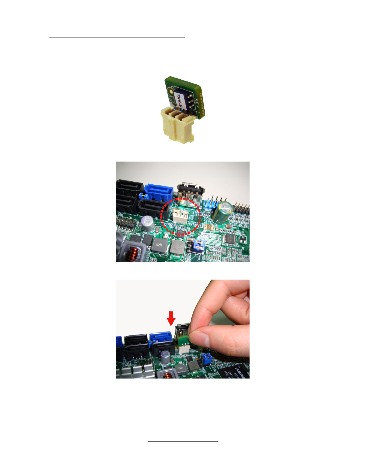
KEY1: PCH DYNAMIC SKUING KEY For Upgrade ROM Module
Pin 1 2 3
Signal
GND FM_SAS_SW_RAID_KEY GND
http://www.TYAN.com
28
Patsburg Upgrade ROM Key Installation
Follow the steps described later to install the Patsburg Upgrade ROM Key.
1. Take out the Patsburg Upgrade ROM Key.
2. Locate the Patsburg Upgrade ROM Header.
3. Insert the Upgrade ROM Key in the direction as the arrow shows.
http://www.TYAN.com
29
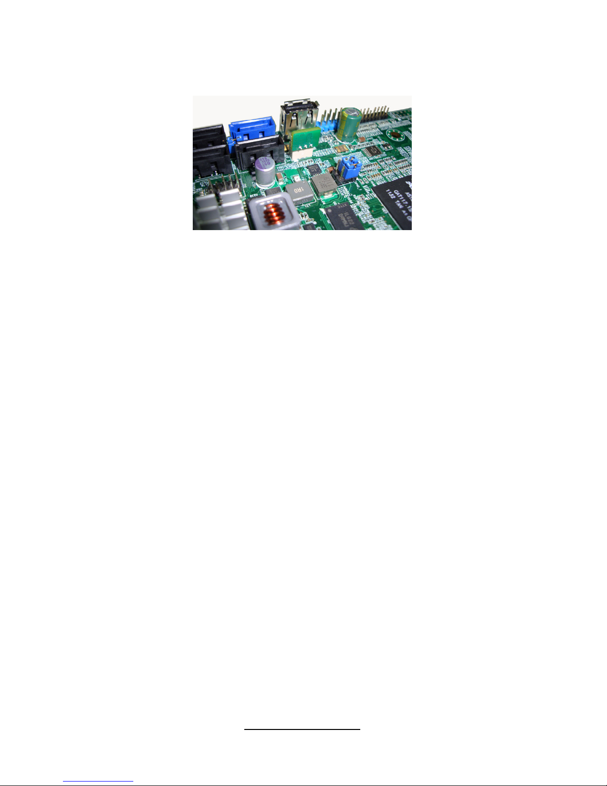
4. You have completed the Patsburg Upgrade ROM Key installation.
http://www.TYAN.com
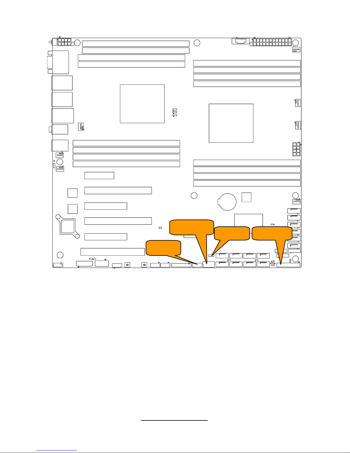
30
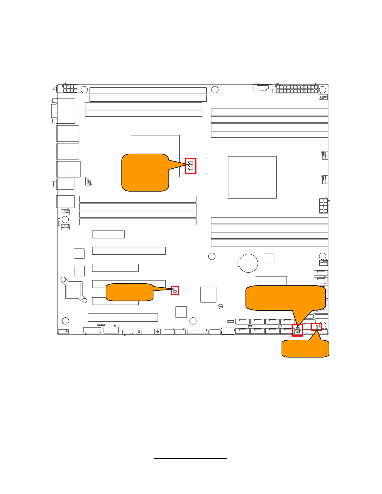
2PHD_1
2PHD
_
2/2PHD_3
2PHD_5
3PHD_3
3PHD_2
3PHD_1
2PHD_4
 Loading...