

TYAN S7040 User Manual

S7040
Version 1.0
Copyright
Copyright © MiTAC Computer Corporation, 2012. All rights reserved. No part of
this manual may be reproduced or translated without prior written consent from
MiTAC Computer Corp.
Trademark
All registered and unregistered trademarks and company names contained in
this manual are property of their respective owners including, but not limited to
the following.
TYAN® is a trademark of MiTAC Computer Corporation
Intel
®
is a trademark of Intel® Corporation.
AMI
®
, AMIBIOS® and combinations thereof are trademarks of AMI Technologies.
Microsoft
®
, Windows® are trademarks of Microsoft Corporation.
Aspeed
®
is a trademark of Aspeed Technology Inc.
Notice
Information contained in this document is furnished by MiTAC Computer
Corporation and has been reviewed for accuracy and r eliability prior to printing.
MiTAC assumes no liability whatsoever, and disclaims any express or implied
warranty, relating to sale and/or use of TYAN
®
products including liability or
warranties relating to fitness for a particular purpose or merchantability. MiTAC
retains the right to make changes to product descriptions and/or specifications
at any time, without notice. In no event will MiTAC be held liable for any direct
or indirect, incidental or consequential damage, loss of use, loss of dat a or other
malady resulting from errors or inaccuracies of information contained in this
document.

http://www.TYAN.com
2
About this guide
This user guide contains the information you need when inst alling and configuring
the motherboard.
How this guide is organized
This guide contains the following parts:
Chapter1: Instruction
This chapter describes the features of the motherboard and the new technology it
supports.
Chapter2: Board Installation
This chapter lists the hardware setup procedures that you need to abide by when
installing system components. It includes description of the jumpers and connectors
on the motherboard.
Chapter3: BIOS Setup
This chapter tells how to change system settings through the BIOS setup menu.
Detailed descriptions of the BIOS parameters are also provided.
Chapter4: Diagnostics
This chapter introduces some BIOS codes and technical terms to provide better
service for the customers.
Appendix: Fan and Temp Sensors
This section aims to help readers identify the locations of some specific Fan and
Temp Sensors on the motherboard. A table of BIOS Temp sensor name
explanation is also included for reader’s reference.

http://www.TYAN.com
3
Contents
Before you begin…................................................................................................4
Chapter 1: Instruction ..........................................................................5
1.1 - Congratulations .............................................................................................5
1.2 - Hardware Specifications................................................................................5
1.3 - Software Specifications...............................................................................16
1.4 - AST2300 User Guide ..................................................................................16
Chapter 2: Board Installation ............................................................ 17
2.1 - Board Image................................................................................................18
2.2 - Block Diagram.............................................................................................19
2.3 - Board Parts, Jumpers and Connectors........................................................20
2.4 - Installing the Processor...............................................................................34
2.5 - Installing the Heatsink .................................................................................37
2.6 - Thermal Interface Material...........................................................................38
2.7 - Tips on Installing Motherboard in Chassis...................................................39
2.8 - Installing the Memory ..................................................................................41
2.9 - Attaching Drive Cables................................................................................45
2.10 - Installing Add-In Cards..............................................................................46
2.11 - Connecting External Devices ....................................................................47
2.12 - Installing the Power Supply.......................................................................48
2.13 - Finishing Up ..............................................................................................48
Chapter 3: BIOS Setup....................................................................... 49
3.1 - About the BIOS............................................................................................49
3.2 - Setup Basics ...............................................................................................49
3.3 - Getting Help ................................................................................................50
3.4 - In Case of Problems....................................................................................50
3.5 - BIOS Main Menu.........................................................................................51
3.6 - BIOS Advanced Menu.................................................................................53
3.7 - Chipset Menu ..............................................................................................82
3.8 - Server Management....................................................................................96
3.9 - Boot Configuration.....................................................................................100
3.10 - Security Menu..........................................................................................102
3.11 - Save & Exit Menu....................................................................................103
Chapter 4: Diagnostics .................................................................... 105
4.1 Flash Utility................................................................................................105
4.2 AMIBIOS Post Code (Aptio) ......................................................................105
Appendix: Fan and Temp Sensors ................................................. 113
Glossary............................................................................................ 117
Technical Support............................................................................ 123
http://www.TYAN.com
4
Before you begin…
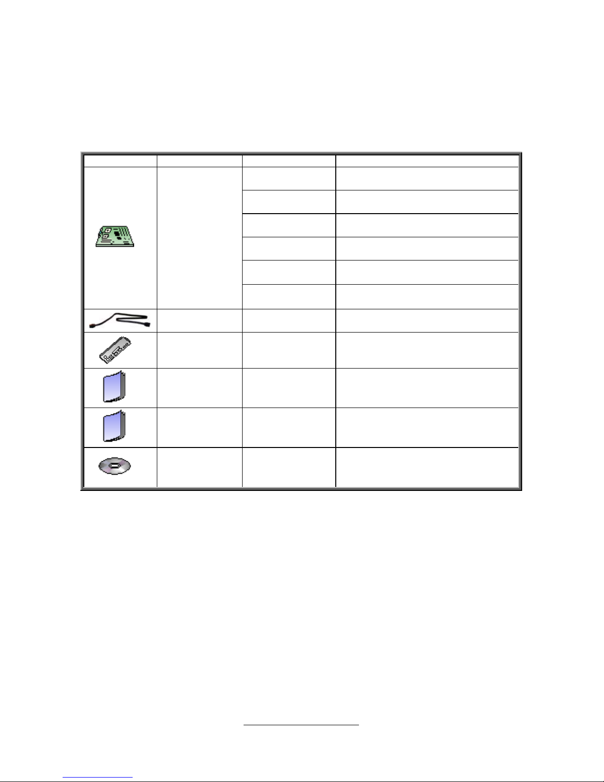
Check the box contents!
The retail motherboard package should contain the following:
Item Name P/N Number Description
5411T4430006
TF-MB;SBU, S7040,
S7040G2NR/MB, R1.0, TYAN
5411T4430007
TF-MB;SBU, S7040,
S7040WGM2NR/MB, R1.0, TYAN
5411T4430008
TF-MB;SBU, S7040,
S7040WGM4NR/MB, R1.0, TYAN
5411T4430009
TF-MB; SBU, S7040,
S7040GM4NR/MB, R1.0, TYAN
5411T4430010
TF-MB; SBU, S7040,
S7040GM2NR/MB, R1.0, TYAN
1x S7040
Motherboard
5411T4430011
TF-MB; SBU, S7040,
S7040WGM2NR5/MB, R1.0, TYAN
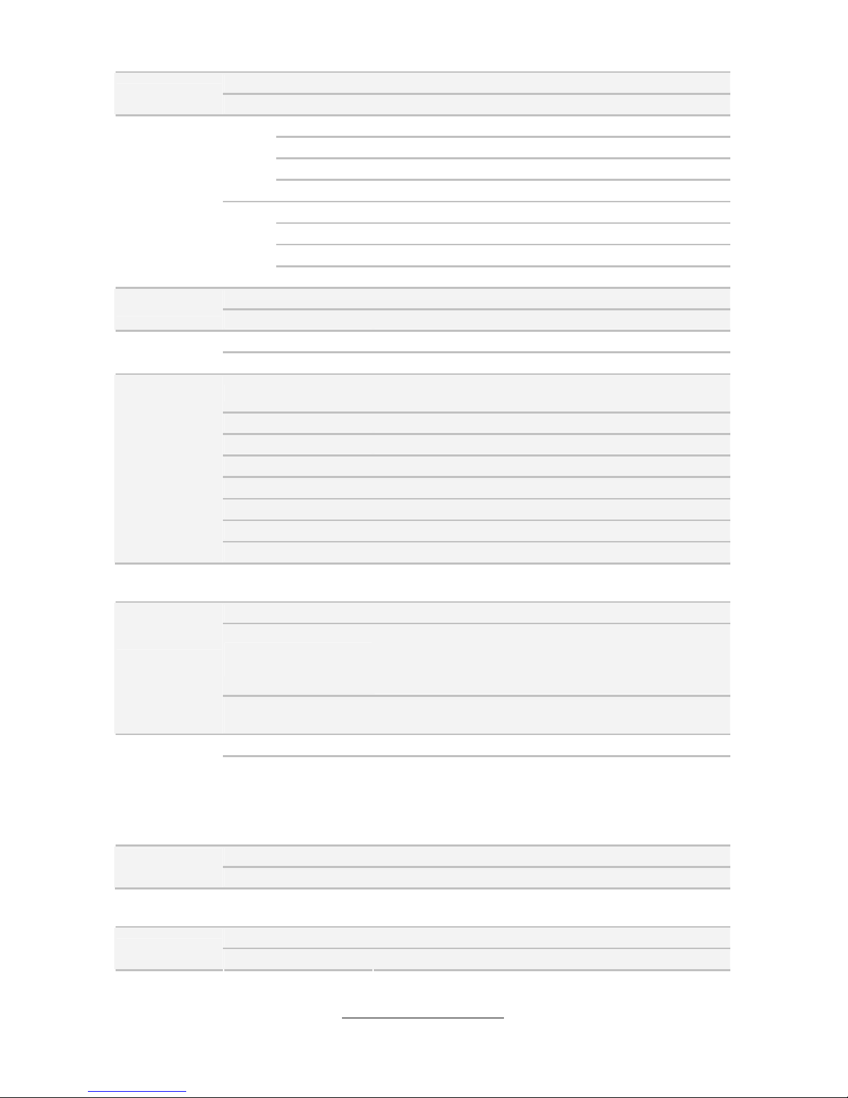
6x Serial
ATA Cable
422736300010
TF-CABLE ASSY; SBU, SATA500MM
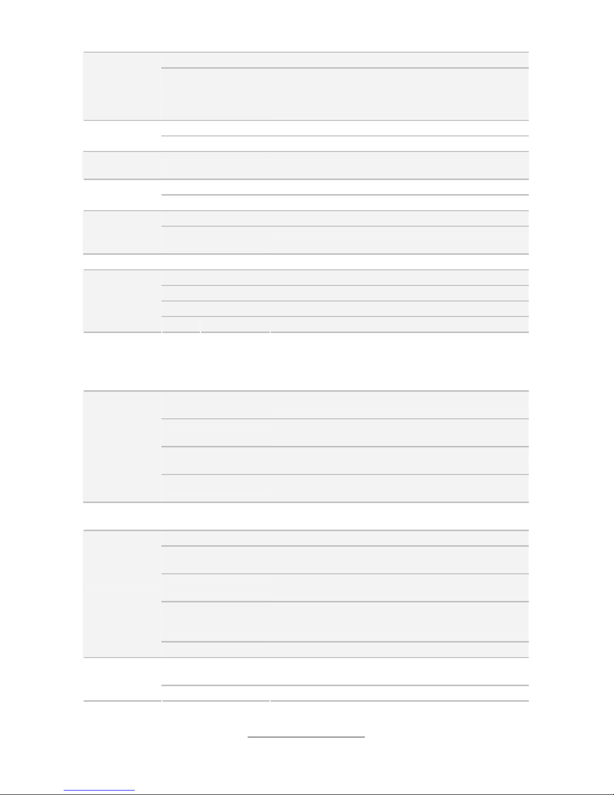
1x I/O Shield
341T44000001
TF-I/O SHIELDING; SBU, SUS,
50012-6AP
1x S7040
User’s
Manual
5615T4430001
TF-MANUAL; SBU, V1.0, USER
MANUAL, D2151-100, S7040
1x S7040 Quick
Reference
Guide
5618T4430002
TF-SINGLE PAGE; SBU, V1.0, Quick
Reference, D2152-100, S7040
1x TYAN®
Driver CD
5651T4390001
TF-SOFTWARE; SBU, TYAN Driver
CD for Intel C600 series Platform
V1.1
IMPORTANT NOTE:
Sales samples may not come with any of the accessories listed above.
If you have ordered a sales sample and you are missing any of the above i tems,
please contact your sales representative to help order accessories.

http://www.TYAN.com
5
Chapter 1: Instruction
1.1 - Congratulations
You have purchased the powerful TYAN
®
S7040 motherboard, based on the Intel®
Patsburg chipset. The S7040 is designed to support dual Intel
®
Xeon E5-2400
Series processors, and up to 288GB of LRDIMM / 144GB of RDIMM / 72GB of
UDIMM DDR3 memory. Leveraging advanced technology from Intel®, the S7040 is
capable of offering scalable 32 and 64-bit computing, high-band width memor y
design, and lightning-fast PCI-E bus implementation.
The S7040 not only empowers you in today’s demand ing IT environment but also
offers a smooth path for future application upgradeability. All of these rich feature
sets provides the S7040 with the power and flexibility to meet demanding
requirements for today’s IT environments.
Remember to visit the TYAN® website at http://www.tyan.com. There you can
find all the information on all TYAN® products as well as all the supporting
documentation, FAQs, Drivers and BIOS upgrades.
1.2 - Hardware Specifications
TYAN S7040 (S7040WGM2NR)
Supported CPU
Series
Intel Xeon Processor E5-2400 Series
Socket Type / Q'ty LGA1356 / (2)
Thermal Design
Power (TDP) wattage
Max up to 95W
Processor
System Bus
Up to 8.0/ 7.2/ 6.4 GT/s with Intel QuickPath
Interconnect (QPI) support
Chipset PCH Intel C602 with upgrade ROM module
Supported DIMM Qty (6)+(3) DIMM slots
DIMM Type / Speed
DDR3/DDR3L 1066 / 1333 / 1600 RDIMM, 1066 /
1333 UDIMM / LRDIMM
Capacity
up to 288GB LRDIMM / 144GB RDIMM / 72GB
UDIMM
Memory channel
3 Channels per CPU / Support 2 R/LR-DIMMs or 2
UDIMMs per channel (CPU 0) / Support 1 R/LRDIMMs or 1 UDIMMs per channel (CPU 1)
Memory
Memory voltage 1.5V or 1.35V
PCI-E
(1) PCI-E x8 slot (x8 link, slot #5) / (1) PCI-E x8 slot
( x4 link, slot #3) / (1) PCI-E x16 slot ( x8 link, slot #4)
Expansion
Slots
PCI (1) PCI 32-bit slot (slot #2)
http://www.TYAN.com
6
Port Q'ty (2) GbE ports
LAN
Controller Intel 82574L
Connector (8) SAS
Controller Intel C602 with TRK-5 upgrade ROM module
Speed 3.0 Gb/s
SAS
RAID RAID 0/1/10 (Intel Integrated RAID upgrade ROM 5)
Connector (6) SATA
Controller Intel C602
Speed (2) 6.0 Gb/s (blue color), (4) 3.0 Gb/s (black color)
Storage
SATA
RAID RAID 0/1/10/5 (Intel RST)
Connector type D-Sub 15-pin
Graphic
Chipset Aspeed AST2300
Chipset Infineon SLB9635 (Optional)
TPM
Version TPM v1.2
USB
(9) USB2.0 ports (4 at rear, 4 via cable, 1 type A
onboard)
COM (1) DB-9 COM Connector / (1) 2*5 PIN COM header
SAS (8) SAS connectors
VGA (1) D-Sub 15-pin VGA port
RJ-45 (2) GbE ports
Power SSI 24-pin + 8-pin + 8-pin power connectors
Front Panel (1) 2x12-pin SSI front panel header
Input /Output
SATA (4) SATA-II and (2) SATA-III connectors
System
Monitoring
Temperature Monitors temperature for CPU & system environment
Onboard Chipset Onboard Aspeed AST2300
AST2300 IPMI
Feature
IPMI 2.0 compliant baseboard management controller
(BMC) / Supports storage over IP and remote
platform-flash / USB 2.0 virtual hub
Server
Management
AST2300 iKVM
Feature
24-bit high quality video compression / 10/100/1000
Mb/s MAC interface
Brand / ROM size AMI / 8MB
BIOS
Feature
Plug and Play (PnP) /PCI2.3 /WfM2.0 /SMBIOS2.3
/PXE boot / ACPI 2.0 power management /Power on
mode after power recovery / User-configurable H/W
monitoring / Auto-configurable of hard disk types
Form Factor SSI CEB
Physical
Dimension
Board Dimension 12"x10.5" (305x267mm)
Operating
System
OS supported list Please visit our Web site for the latest update.
FCC (DoC) Class B
Regulation
CE (DoC) Yes

http://www.TYAN.com
7
Operating Temp. 10° C ~ 35° C (50° F~ 95° F)
Operating
Environment
Non-operating
Temp.
- 40° C ~ 70° C (-40° F ~ 158° F)
RoHS RoHS 6/6 Compliant Yes
Manual (1) User's manual / (1) Quick Ref. Guide
Installation CD (1) TYAN installation CD
I/O Shield (1) I/O Shield
Package
Contains
Cable SATA (6) SATA signal cables
TYAN S7040 (S7040GM4NR)
Supported CPU
Series
Intel Xeon Processor E5-2400 Series
Socket Type / Q'ty LGA1356 / (2)
Thermal Design
Power (TDP) wattage
Max up to 95W
Processor
System Bus
Up to 8.0/ 7.2/ 6.4 GT/s with Intel QuickPath
Interconnect (QPI) support
Chipset PCH Intel C602
Supported DIMM Qty (6)+(3) DIMM slots
DIMM Type / Speed
DDR3/DDR3L 1066 / 1333 / 1600 RDIMM, 1066 /
1333 UDIMM / LRDIMM
Capacity
up to 288GB LRDIMM / 144GB RDIMM / 72GB
UDIMM
Memory channel
3 Channels per CPU / Support 2 R/LR-DIMMs or 2
UDIMMs per channel (CPU 0) / Support 1 R/LRDIMMs or 1 UDIMMs per channel (CPU 1)
Memory
Memory voltage 1.5V or 1.35V
PCI-E
(1) PCI-E x8 slot (x8 link, slot #5) / (1) PCI-E x8 slot
(x4 link, slot #3) / (1) PCI-E x16 slot (x8 link, slot #4)
Expansion
Slots
PCI (1) PCI 32-bit slot (slot #2)
Port Q'ty (4) GbE ports
LAN
Controller Intel 82574L / Intel I350-AM2
Connector (10) SATA; (2) 6G + (8) 3G
Controller Intel C602
Speed (2) 6.0 Gb/s (blue color), (8) 3.0 Gb/s (black color)
Storage SATA
RAID RAID 0/1/10/5 (Intel RST)
Connector type D-Sub 15-pin
Graphic
Chipset Aspeed AST2300
Chipset Infineon SLB9635 (Optional)
TPM
Version TPM v1.2

http://www.TYAN.com
8
USB
(9) USB2.0 ports (4 at rear, 4 via cable, 1 type A
onboard)
COM (1) DB-9 COM Connector / (1) 2*5 PIN COM header
VGA (1) D-Sub 15-pin VGA port
RJ-45 (4) GbE ports
Power SSI 24-pin + 8-pin + 8-pin power connectors
Front Panel (1) 2x12-pin SSI front panel header
Input /Output
SATA (2) SATA-III and (8) SATA-II connectors
Voltage
Monitors voltage for CPU, memory, chipset & power
supply
System
Monitoring
Temperature Monitors temperature for CPU & system environment
Onboard Chipset Onboard Aspeed AST2300
AST2300 IPMI
Feature
IPMI 2.0 compliant baseboard management controller
(BMC) / Supports storage over IP and remote
platform-flash / USB 2.0 virtual hub
Server
Management
AST2300 iKVM
Feature
24-bit high quality video compression / 10/100/1000
Mb/s MAC interface
Brand / ROM size AMI / 8MB
BIOS
Feature
Plug and Play (PnP) /PCI2.3 /WfM2.0 /SMBIOS2.3
/PXE boot / ACPI 2.0 power management /Power on
mode after power recovery / User-configurable H/W
monitoring / Auto-configurable of hard disk types
Form Factor SSI CEB
Physical
Dimension
Board Dimension 12"x10.5" (305x267mm)
Operating
System
OS supported list Please visit our Web site for the latest update.
FCC (DoC) Class B
Regulation
CE (DoC) Yes
Operating Temp. 10° C ~ 35° C (50° F~ 95° F)
Operating
Environment
Non-operating
Temp.
- 40° C ~ 70° C (-40° F ~ 158° F)
RoHS RoHS 6/6 Compliant Yes
Manual (1) User's manual / (1) Quick Ref. Guide
Installation CD (1) TYAN installation CD
I/O Shield (1) I/O Shield
Package
Contains
Cable SATA (6) SATA signal cables

http://www.TYAN.com
9
TYAN S7040 (S7040G2NR)
Supported CPU
Series
Intel Xeon Processor E5-2400 Series
Socket Type / Q'ty LGA1356 / (2)
Thermal Design
Power (TDP) wattage
Max up to 95W
Processor
System Bus
Up to 8.0/ 7.2/ 6.4 GT/s with Intel QuickPath
Interconnect (QPI) support
Chipset PCH Intel C602
Supported DIMM Qty (6)+(3) DIMM slots
DIMM Type / Speed
DDR3/DDR3L 1066 / 1333 / 1600 RDIMM, 1066 /
1333 UDIMM / LRDIMM
Capacity
up to 288GB LRDIMM / 144GB RDIMM / 72GB
UDIMM
Memory channel
3 Channels per CPU / Support 2 R/LR-DIMMs or 2
UDIMMs per channel (CPU 0) / Support 1 R/LRDIMMs or 1 UDIMMs per channel (CPU 1)
Memory
Memory voltage 1.5V or 1.35V
PCI-E
(1) PCI-E x8 slot (x8 link, slot #5) / (1) PCI-E x8 slot
( x4 link, slot #3) / (1) PCI-E x16 slot ( x8 link, slot #4)
Expansion
Slots
PCI (1) PCI 32-bit slot (slot #2)
Port Q'ty (2) GbE ports
LAN
Controller Intel 82574L
Connector (10) SATA; (2) 6G + (8) 3G
Controller Intel C602
Speed (2) 6.0 Gb/s (blue color), (8) 3.0 Gb/s (black color)
Storage SATA
RAID RAID 0/1/10/5 (Intel RST)
Connector type D-Sub 15-pin
Graphic
Chipset Aspeed AST1300
Chipset Infineon SLB9635 (Optional)
TPM
Version TPM v1.2
USB
(9) USB2.0 ports (4 at rear, 4 via cable, 1 type A
onboard)
COM (1) DB-9 COM Connector / (1) 2*5 PIN COM header
VGA (1) D-Sub 15-pin VGA port
RJ-45 (2) GbE ports
Power SSI 24-pin + 8-pin + 8-pin power connectors
Front Panel (1) 2x12-pin SSI front panel header
Input /Output
SATA (2) SATA-III and (8) SATA-II connectors
Voltage
Monitors voltage for CPU, memory, chipset & power
supply
System
Monitoring
Temperature
Monitors temperature for CPU & system environment
http://www.TYAN.com
10
Brand / ROM size AMI / 8MB
BIOS
Feature
Plug and Play (PnP) /PCI2.3 /WfM2.0 /SMBIOS2.3
/PXE boot / ACPI 2.0 power management /Power on
mode after power recovery / User-configurable H/W
monitoring / Auto-configurable of hard disk types
Form Factor SSI CEB
Physical
Dimension
Board Dimension 12"x10.5" (305x267mm)
Operating
System
OS supported list Please visit our Web site for the latest update.
FCC (DoC) Class B
Regulation
CE (DoC) Yes
Operating Temp. 10° C ~ 35° C (50° F~ 95° F)
Operating
Environment
Non-operating
Temp.
- 40° C ~ 70° C (-40° F ~ 158° F)
RoHS RoHS 6/6 Compliant Yes
Manual (1) User's manual / (1) Quick Ref. Guide
Installation CD (1) TYAN installation CD
I/O Shield (1) I/O Shield
Package
Contains
Cable SATA (6) SATA signal cables
TYAN S7040 (S7040WGM4NR(BTO)
Supported CPU
Series
Intel Xeon Processor E5-2400 Series
Socket Type / Q'ty
LGA1356 / (2)
Thermal Design
Power (TDP) wattage
Max up to 95W
Processor
System Bus
Up to 8.0/ 7.2/ 6.4 GT/s with Intel QuickPath
Interconnect (QPI) support
Chipset PCH
Intel C602 with upgrade ROM module
Supported DIMM Qty (6)+(3) DIMM slots
DIMM Type / Speed
DDR3/DDR3L 1066 / 1333 / 1600 RDIMM, 1066 /
1333 UDIMM / LRDIMM
Capacity
up to 288GB LRDIMM / 144GB RDIMM / 72GB
UDIMM
Memory channel
3 Channels per CPU / Support 2 R/LR-DIMMs or 2
UDIMMs per channel (CPU 0) / Support 1 R/LRDIMMs or 1 UDIMMs per channel (CPU 1)
Memory
Memory voltage 1.5V or 1.35V
PCI-E
(1) PCI-E x8 slot (x8 link, slot #5) / (1) PCI-E x8 slot
(x4 link, slot #3) / (1) PCI-E x16 slot (x8 link, slot #4)
Expansion
Slots
PCI (1) PCI 32-bit slot (slot #2)

http://www.TYAN.com
11
Port Q'ty (4) GbE ports
LAN
Controller Intel 82574L / Intel I350-AM2
Connector (8) SAS
Controller Intel C602 with TRK-5 upgrade ROM module
Speed 3.0 Gb/s
SAS
RAID RAID 0/1/10 (Intel Integrated RAID upgrade ROM 5)
Connector (6) SATA
Controller Intel C602
Speed (2) 6.0 Gb/s (blue color), (4) 3.0 Gb/s (black color)
Storage
SATA
RAID RAID 0/1/10/5 (Intel RST)
Connector type D-Sub 15-pin
Graphic
Chipset Aspeed AST2300
Chipset Infineon SLB9635 (Optional)
TPM
Version TPM v1.2
USB
(9) USB2.0 ports (4 at rear, 4 via cable, 1 type A
onboard)
COM (1) DB-9 COM Connector / (1) 2*5 PIN COM header
SAS (8) SAS connectors
VGA (1) D-Sub 15-pin VGA port
RJ-45 (4) GbE ports
Power SSI 24-pin + 8-pin + 8-pin power connectors
Front Panel (1) 2x12-pin SSI front panel header
Input /Output
SATA (4) SATA-II and (2) SATA-III connectors
Voltage
Monitors voltage for CPU, memory, chipset & power
supply
System
Monitoring
Temperature Monitors temperature for CPU & system environment
Onboard Chipset Onboard Aspeed AST2300
AST2300 IPMI
Feature
IPMI 2.0 compliant baseboard management controller
(BMC) / Supports storage over IP and remote
platform-flash / USB 2.0 virtual hub
Server
Management
AST2300 iKVM
Feature
24-bit high quality video compression / 10/100/1000
Mb/s MAC interface
Brand / ROM size AMI / 8MB
BIOS
Feature
Plug and Play (PnP) /PCI2.3 /WfM2.0 /SMBIOS2.3
/PXE boot / ACPI 2.0 power management /Power on
mode after power recovery / User-configurable H/W
monitoring / Auto-configurable of hard disk types
Form Factor SSI CEB
Physical
Dimension
Board Dimension 12"x10.5" (305x267mm)
Operating
System
OS supported list Please visit our Web site for the latest update.
FCC (DoC) Class B
Regulation
CE (DoC) Yes
http://www.TYAN.com
12
Operating Temp. 10° C ~ 35° C (50° F~ 95° F)
Operating
Environment
Non-operating
Temp.
- 40° C ~ 70° C (-40° F ~ 158° F)
RoHS RoHS 6/6 Compliant Yes
Manual (1) User's manual / (1) Quick Ref. Guide
Installation CD (1) TYAN installation CD
I/O Shield (1) I/O Shield
Package
Contains
Cable SATA (6) SATA signal cables
TYAN S7040 (S7040WGM2NR5(BTO)
Supported CPU
Series
Intel Xeon Processor E5-2400 Series
Socket Type / Q'ty LGA1356 / (2)
Thermal Design
Power (TDP) wattage
Max up to 95W
Processor
System Bus
Up to 8.0/ 7.2/ 6.4 GT/s with Intel QuickPath
Interconnect (QPI) support
Chipset PCH Intel C602 with upgrade ROM module
Supported DIMM Qty (6)+(3) DIMM slots
DIMM Type / Speed
DDR3/DDR3L 1066 / 1333 / 1600 RDIMM, 1066 /
1333 UDIMM / LRDIMM
Capacity
up to 288GB LRDIMM / 144GB RDIMM / 72GB
UDIMM
Memory channel
3 Channels per CPU / Support 2 R/LR-DIMMs or 2
UDIMMs per channel (CPU 0) / Support 1 R/LRDIMMs or 1 UDIMMs per channel (CPU 1)
Memory
Memory voltage 1.5V or 1.35V
PCI-E
(1) PCI-E x8 slot (x8 link, slot #5) / (1) PCI-E x8 slot
( x4 link, slot #3) / (1) PCI-E x16 slot ( x8 link, slot #4)
Expansion
Slots
PCI (1) PCI 32-bit slot (slot #2)
Port Q'ty (2) GbE ports
LAN
Controller Intel 82574L
Connector (8) SAS
Controller Intel C602 with TRK-6 upgrade ROM module
Speed 3.0 Gb/s
SAS
RAID RAID 0/1/10/5 (Intel Integrated RAID upgrade ROM 6)
Connector (6) SATA
Controller Intel C602
Speed (2) 6.0 Gb/s (blue color), (4) 3.0 Gb/s (black color)
Storage
SATA
RAID RAID 0/1/10/5 (Intel RST)
Connector type D-Sub 15-pin
Graphic
Chipset Aspeed AST2300
http://www.TYAN.com
13
Chipset Infineon SLB9635 (Optional)
TPM
Version TPM v1.2
USB
(9) USB2.0 ports (4 at rear, 4 via cable, 1 type A
onboard)
COM (1) DB-9 COM Connector / (1) 2*5 PIN COM header
SAS (8) SAS connectors
VGA (1) D-Sub 15-pin VGA port
RJ-45 (2) GbE ports
Power SSI 24-pin + 8-pin + 8-pin power connectors
Front Panel (1) 2x12-pin SSI front panel header
Input /Output
SATA (4) SATA-II and (2) SATA-III connectors
Voltage
Monitors voltage for CPU, memory, chipset & power
supply
System
Monitoring
Temperature Monitors temperature for CPU & system environment
Onboard Chipset Onboard Aspeed AST2300
AST2300 IPMI
Feature
IPMI 2.0 compliant baseboard management controller
(BMC) / Supports storage over IP and remote
platform-flash / USB 2.0 virtual hub
Server
Management
AST2300 iKVM
Feature
24-bit high quality video compression / 10/100/1000
Mb/s MAC interface
Brand / ROM size AMI / 8MB
BIOS
Feature
Plug and Play (PnP) /PCI2.3 /WfM2.0 /SMBIOS2.3
/PXE boot / ACPI 2.0 power management /Power on
mode after power recovery / User-configurable H/W
monitoring / Auto-configurable of hard disk types
Form Factor SSI CEB
Physical
Dimension
Board Dimension 12"x10.5" (305x267mm)
Operating
System
OS supported list Please visit our Web site for the latest update.
FCC (DoC) Class B
Regulation
CE (DoC) Yes
Operating Temp. 10° C ~ 35° C (50° F~ 95° F)
Operating
Environment
Non-operating
Temp.
- 40° C ~ 70° C (-40° F ~ 158° F)
RoHS RoHS 6/6 Compliant Yes
Manual (1) User's manual / (1) Quick Ref. Guide
Installation CD (1) TYAN installation CD
I/O Shield (1) I/O Shield
Package
Contains
Cable SATA (6) SATA signal cables
http://www.TYAN.com
14
TYAN S7040 (S7040GM2NR)
Supported CPU
Series
Intel Xeon Processor E5-2400 Series
Socket Type / Q'ty LGA1356 / (2)
Thermal Design
Power (TDP) wattage
Max up to 95W
Processor
System Bus
Up to 8.0/ 7.2/ 6.4 GT/s with Intel QuickPath
Interconnect (QPI) support
Chipset PCH Intel C602
Supported DIMM Qty (6)+(3) DIMM slots
DIMM Type / Speed
DDR3/DDR3L 1066 / 1333 / 1600 RDIMM, 1066 /
1333 UDIMM / LRDIMM
Capacity
up to 288GB LRDIMM / 144GB RDIMM / 72GB
UDIMM
Memory channel
3 Channels per CPU / Support 2 R/LR-DIMMs or 2
UDIMMs per channel (CPU 0) / Support 1 R/LRDIMMs or 1 UDIMMs per channel (CPU 1)
Memory
Memory voltage 1.5V or 1.35V
PCI-E
(1) PCI-E x8 slot (x8 link, slot #5) / (1) PCI-E x8 slot
( x4 link, slot #3) / (1) PCI-E x16 slot ( x8 link, slot #4)
Expansion
Slots
PCI (1) PCI 32-bit slot (slot #2)
Port Q'ty (2) GbE ports
LAN
Controller Intel 82574L
Connector (10) SATA; (2) 6G + (8) 3G
Controller Intel C602
Speed (2) 6.0 Gb/s (blue color), (8) 3.0 Gb/s (black color)
Storage SATA
RAID RAID 0/1/10/5 (Intel RST)
Connector type D-Sub 15-pin
Graphic
Chipset Aspeed AST2300
Chipset Infineon SLB9635 (Optional)
TPM
Version TPM v1.2
USB
(9) USB2.0 ports (4 at rear, 4 via cable, 1 type A
onboard)
COM (1) DB-9 COM Connector / (1) 2*5 PIN COM header
VGA (1) D-Sub 15-pin VGA port
RJ-45 (2) GbE ports
Power SSI 24-pin + 8-pin + 8-pin power connectors
Front Panel (1) 2x12-pin SSI front panel header
Input /Output
SATA (2) SATA-III and (8) SATA-II connectors
Voltage
Monitors voltage for CPU, memory, chipset & power
supply
System
Monitoring
Temperature
Monitors temperature for CPU & system environment
http://www.TYAN.com
15
Onboard Chipset Onboard Aspeed AST2300
AST2300 IPMI
Feature
IPMI 2.0 compliant baseboard management controller
(BMC) / Supports storage over IP and remote
platform-flash / USB 2.0 virtual hub
Server
Management
AST2300 iKVM
Feature
24-bit high quality video compression / 10/100/1000
Mb/s MAC interface
Brand / ROM size AMI / 8MB
BIOS
Feature
Plug and Play (PnP) /PCI2.3 /WfM2.0 /SMBIOS2.3
/PXE boot / ACPI 2.0 power management /Power on
mode after power recovery / User-configurable H/W
monitoring / Auto-configurable of hard disk types
Form Factor SSI CEB
Physical
Dimension
Board Dimension 12"x10.5" (305x267mm)
Operating
System
OS supported list Please visit our Web site for the latest update.
FCC (DoC) Class B
Regulation
CE (DoC) Yes
Operating Temp. 10° C ~ 35° C (50° F~ 95° F)
Operating
Environment
Non-operating
Temp.
- 40° C ~ 70° C (-40° F ~ 158° F)
RoHS RoHS 6/6 Compliant Yes
Manual (1) User's manual / (1) Quick Ref. Guide
Installation CD (1) TYAN installation CD
I/O Shield (1) I/O Shield
Package
Contains
Cable SATA (6) SATA signal cables
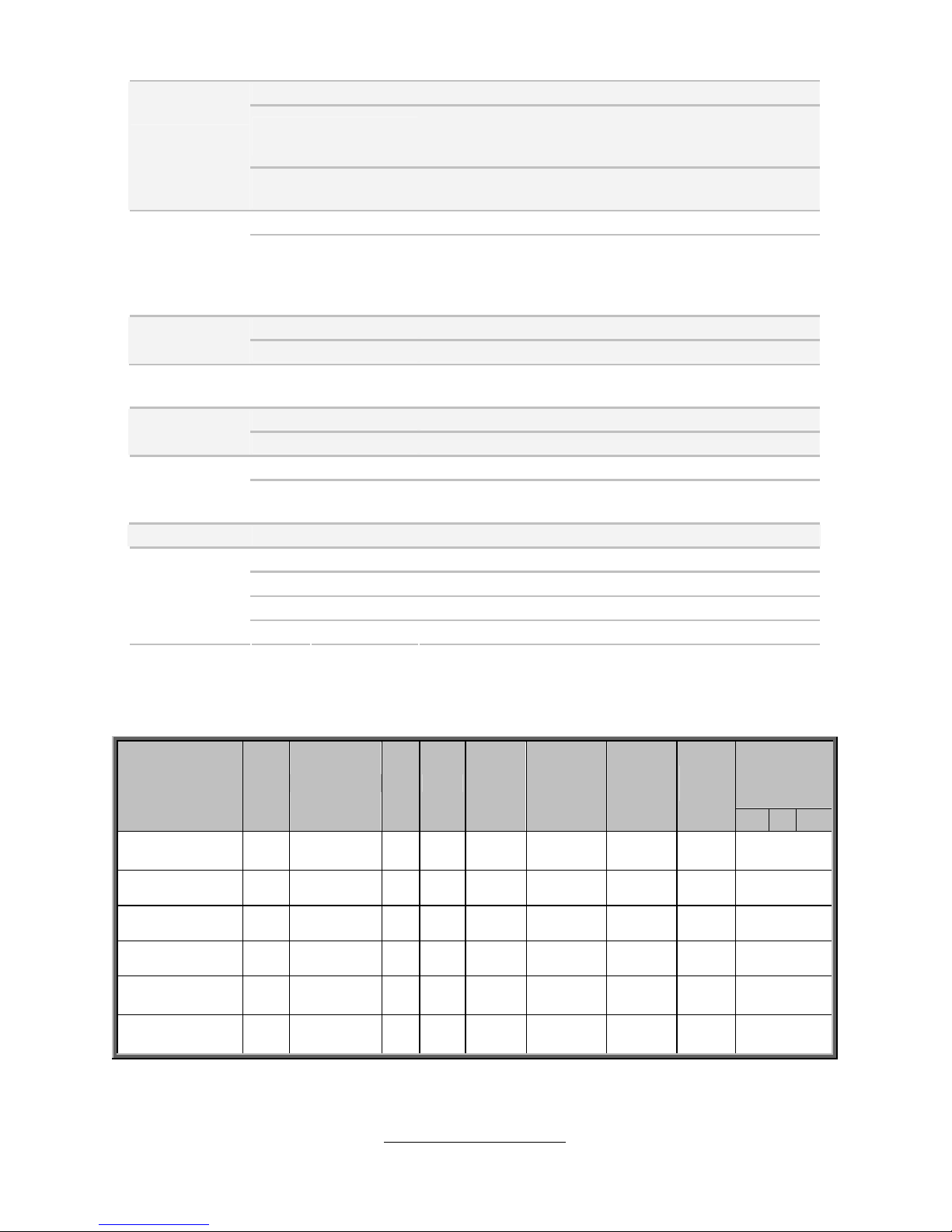
S7040 SKU Comparison Table
Expansion
-slot
Model Chip PCH
LAN
1G
BMC
SAS
3 Gb/s
SAS Raid
SATA
6 Gb/s
SATA
3 Gb/s
X16 X8 PCI
S7040WGM2NR
C602
Pastburg-
A+ROM5
2 Yes 8 0/1/10 2 4 1/2/1
S7040GM2NR
C602 Pastburg-A 2 Yes 0 No 2 8 1/2/1
S7040GM4NR
C602 Pastburg-A 4 Yes 0 No 2 8 1/2/1
S7040G2NR
C602 Pastburg-A 2 No 0 No 2 8 1/2/1
S7040WGM4NR
[BTO]
C602
Pastburg-
A+ROM5
4 Yes 8 0/1/10 2 4 1/2/1
S7040WGM2NR5
[BTO]
C602
Pastburg-
A+ROM6
2 Yes 8 0/1/10/5 2 4 1/2/1

http://www.TYAN.com
16
1.3 - Software Specifications
For OS (operation system) support, please check the TYAN
®
website for the latest
information.
1.4 - AST2300 User Guide
Please visit our Web site for the latest AST2300 Configuration Guide at
http://www.tyan.com
.
http://www.TYAN.com
17
Chapter 2: Board Installation
You are now ready to install your motherboard.
How to install our products right… the first time
The first thing you should do is reading this user’s manual. It contains important
information that will make configuration and setup much easier. Here are some
precautions you should take when installing your motherboard:
(1) Ground yourself properly before removing your motherboard from the
antistatic bag. Unplug the power from your computer power supply and
then touch a safely grounded object to release static charge (i.e. power
supply case). For the safest conditions, TYAN® recommends wearing a
static safety wrist strap.
(2) Hold the motherboard by its edges and do not touch the bottom of the
board, or flex the board in any way.
(3) Avoid touching the motherboard components, IC chips, connectors,
memory modules, and leads.
(4) Place the motherboard on a grounded antistatic surface or on the antistatic
bag that the board was shipped in.
(5) Inspect the board for damage.
The following pages include details on how to install your motherboard into your
chassis, as well as installing the processor, memory, disk drives and cables.
Caution!
1. To avoid damaging the motherboard and associated
components, do not use torq ue force greater than 7kgf/cm
(6.09 lb/in) on each mounting screw for motherboard
installation.
2. Do not apply power to the board if it has been damaged.
http://www.TYAN.com
18
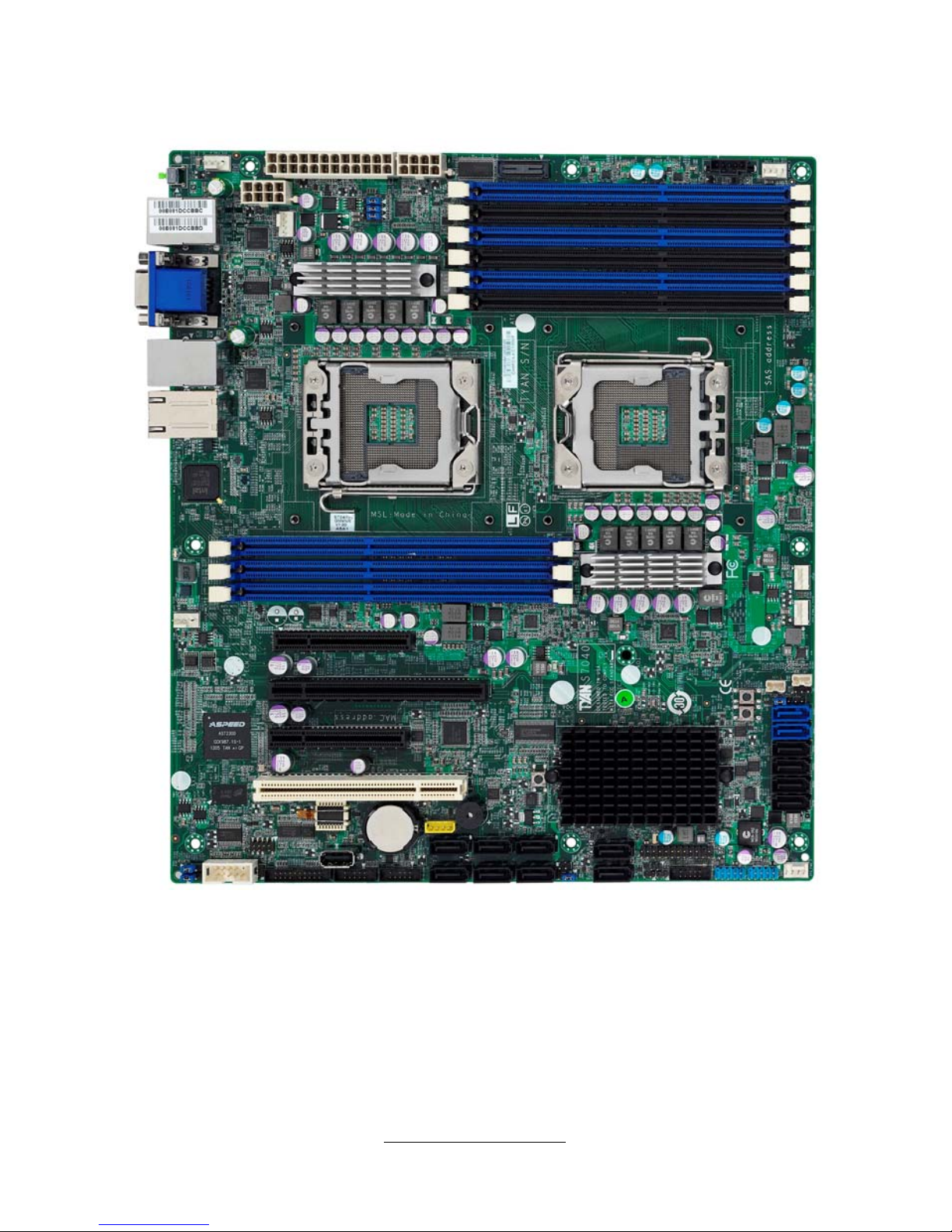
2.1 - Board Image
S7040
This diagram is representative of the latest motherboard revision available at the
time of publishing. The board you receive may not look exactly like the above
diagram.
http://www.TYAN.com
19
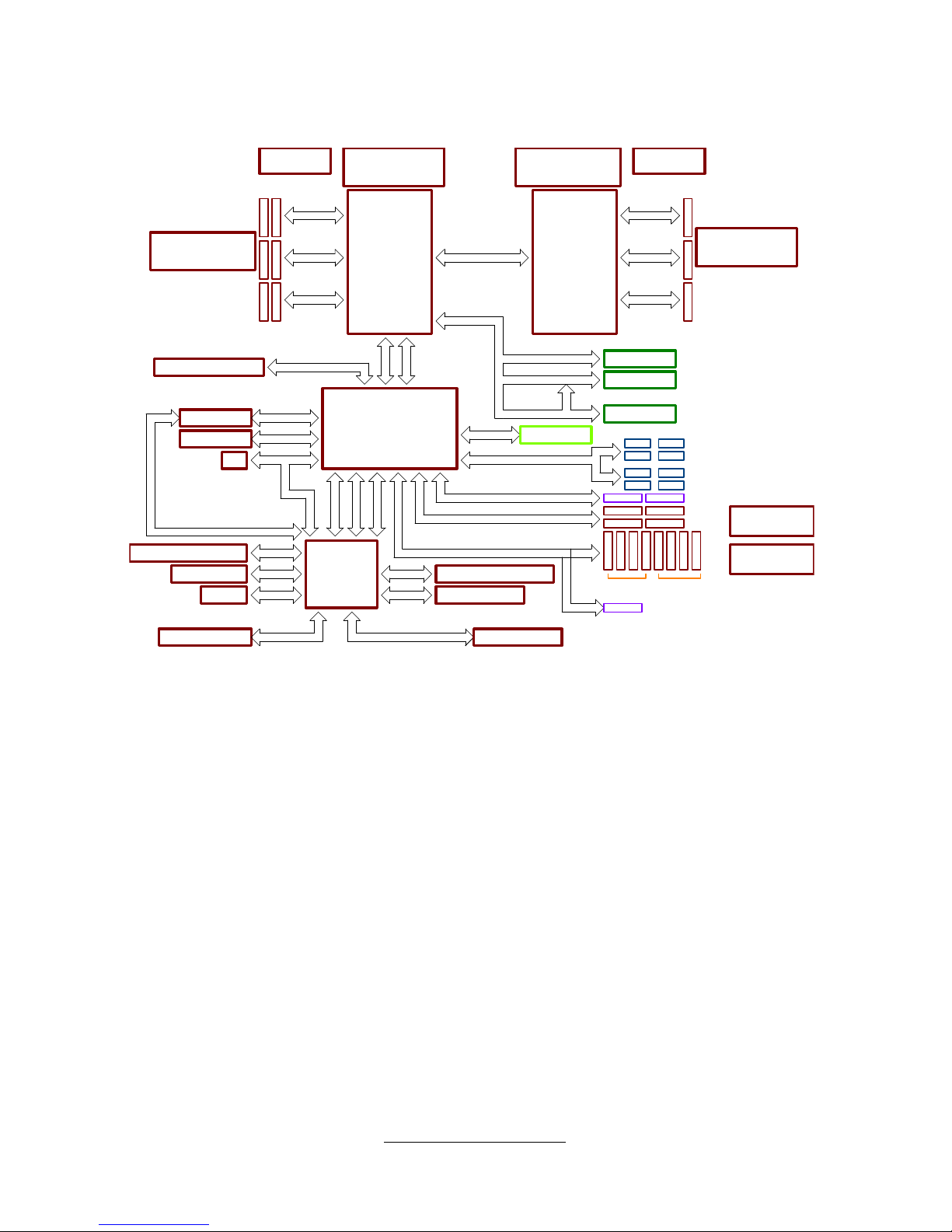
2.2 - Block Diagram
SAS5
SAS6
SAS7
SAS8
SAS1
PCI Express x8
Front Rear
CPU 1
Sandy Bridge - EN
(Soc ket B2 )
Intel P atsbur g
PCH-A
ASpeed IBMC
AST 2300
COM Port
Smart Fan Controller
USB 2.0
USB 2.0
PCI Express x8
PWM Controller=ISL6353
Driver = 6620
Max Power 45W
PVTT = ISL95870
Max Power 21W
Vco re Con troller IS L636 4
Driver=ISL6622
TDP 95W
Vco re Con troller IS L6364
DRIVE R 6622
TD P 95W
PVTT = ISL95870
Max Power 21W
PCIE3
PCIE2
x2
DDRIII
Channel B Channel E
Channel A
Channel C
USB 2.0
USB 2.0
D-Sub Connector
RGB
Clock Generator
ICS ICS932SQ420
DDRIII
Channel D
DDR III
Channel F
CPU 0
Sandy Bridge - EN
(Socket B2)
PCIE1
DDRIII DDRIII
DDRIIIDDRIII
DDR III
DDR III
64Mb SPI System ROM
TPM
LPC Interfa ce
QPI Port 0 (8.0GT/s)
Cloc k Buffe r
ICS ICS9ZX21901B
PCI Express x4
Voltage and Thermal senser
PCIE Gen3 x8 Slot#4
DMI2 X4
PCIE Gen3 x8 Slot#5
PCIE Gen3 x4 Slot#3
PCIE Gen 2 *4
PCIE Gen2 x1
Intel 3 50 GBla n Por t#1& 2
82574L GB Port#4
SPI in terface
PCIE Gen2 x1
NCSI Interface 1
SAS (3.0 Gb/s)
SPI interface
SAS2
SAS3
SAS4
SATA Gen3 (6.0Gb/s)
SATA Gen2 (3.0Gb/s)
SATA1 SATA2
SATA3 SATA4
SATA5
SPI BMC FW flash ROM
SATA6
DDR3 Frame Buffer Memory
BMC FW 16M bit
USB 2.0
USB 2.0
USB 2.0
4x PCIE Gen2 Interface
USB 2.0
PCIE Upli nk X4
PCI 3.0
PCI 3.0 Slot#2
PCI1
TYPE A
PWM Contr oller =ISL63 53
Driver = 6620
Max Power 90WA
USB 2.0
USB 2.0
82574L GB Port#3
PCIE Gen2 x1
S7040
http://www.TYAN.com
20
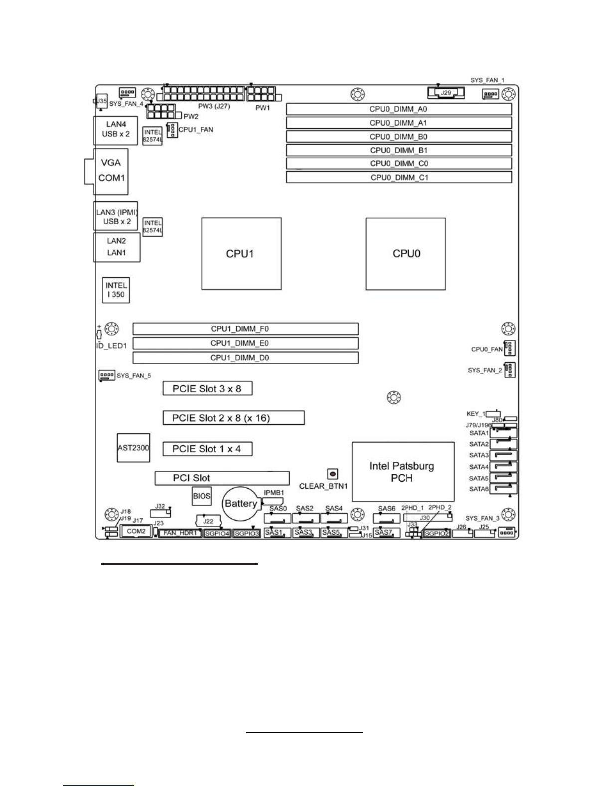
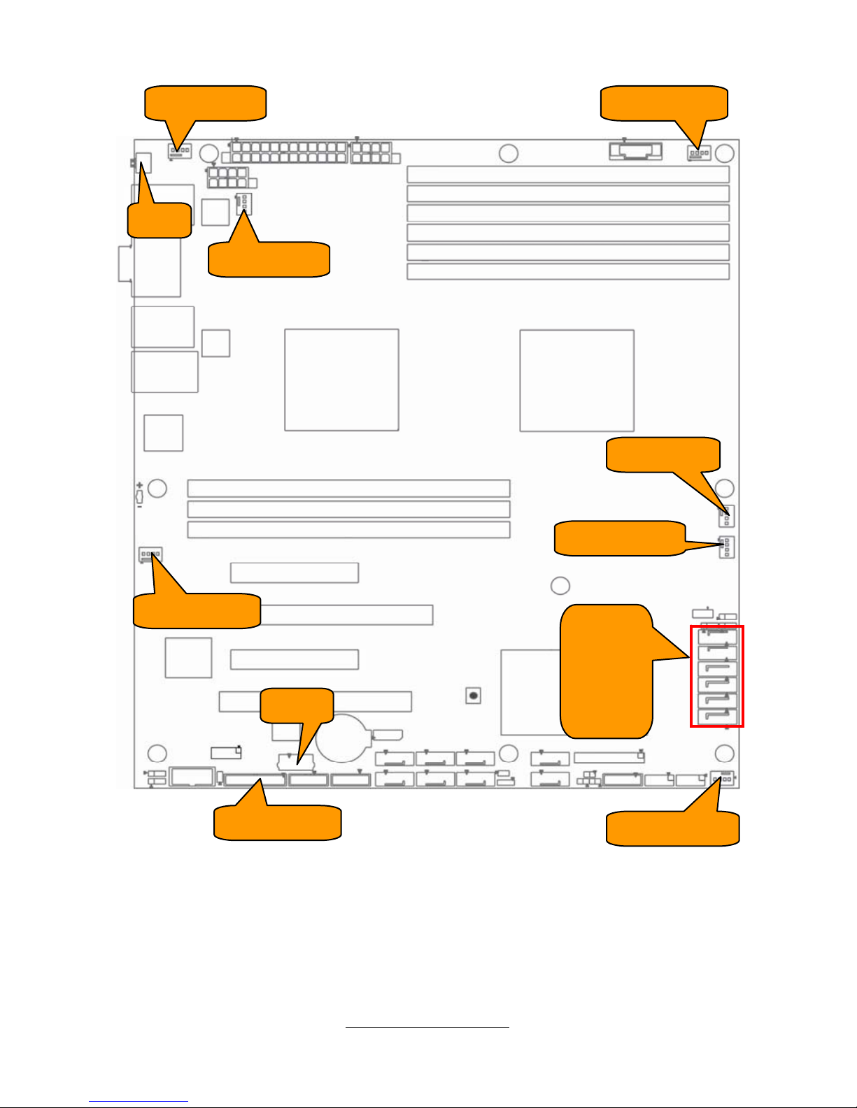
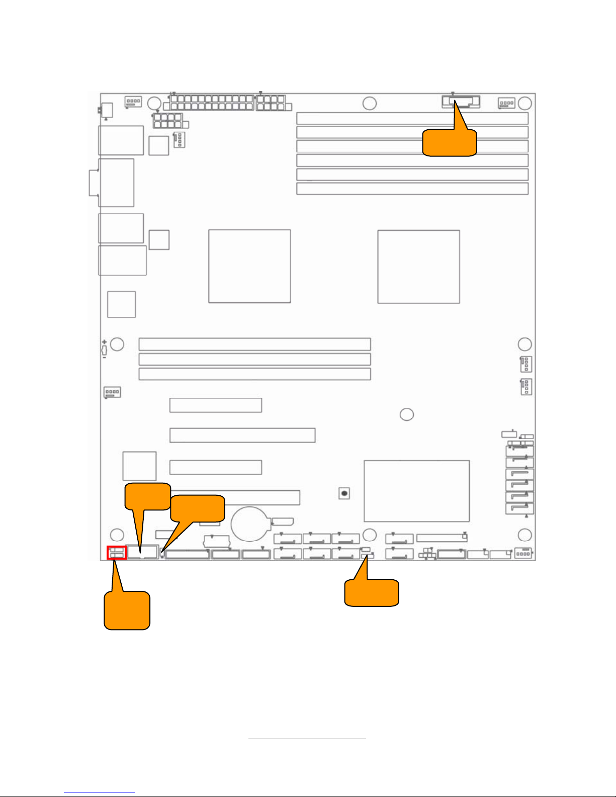
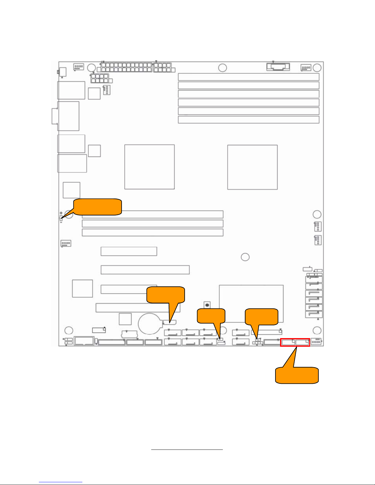
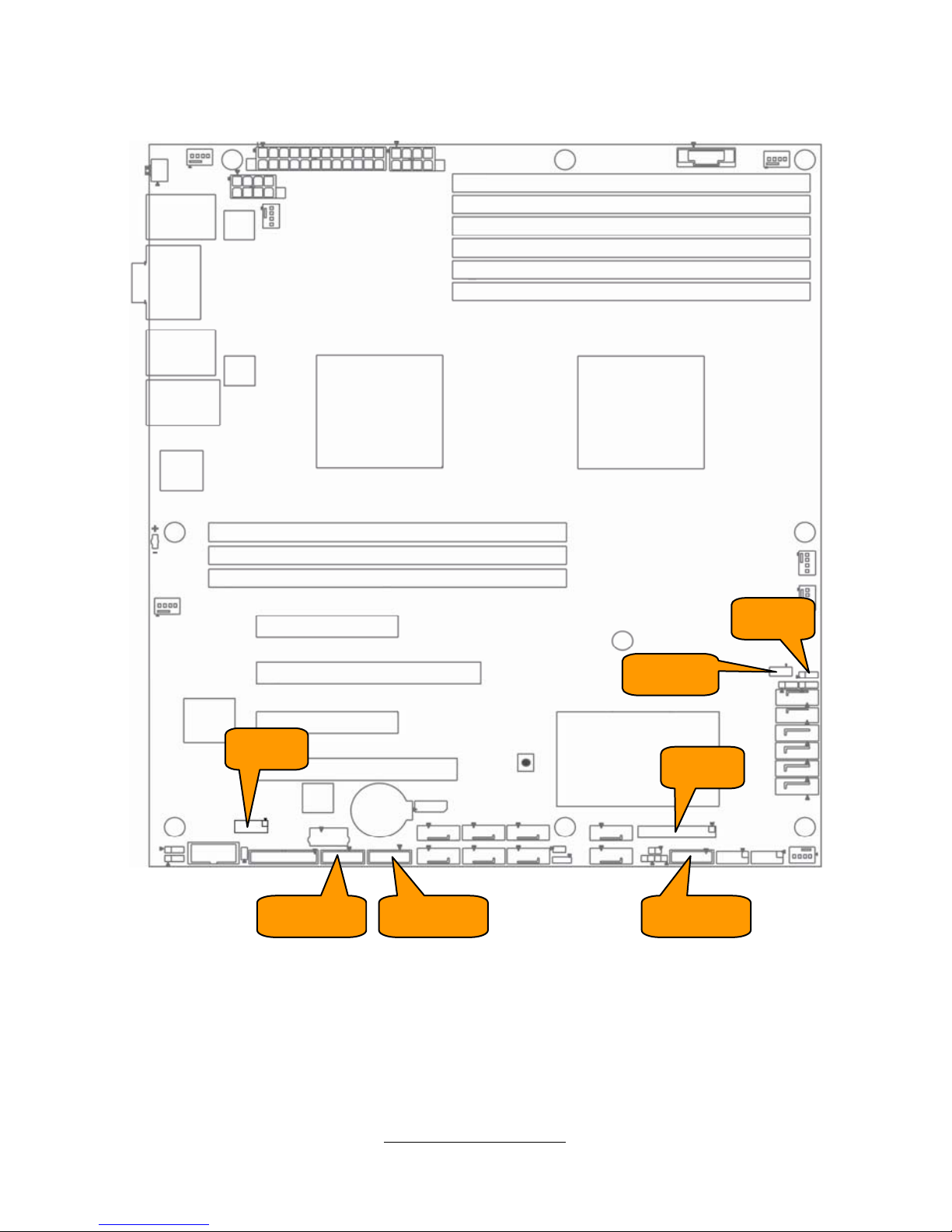
2.3 - Board Parts, Jumpers and Connectors
Important Notes to the User
• "▲" indicates the location of "Pin 1".
• Jumpers not indicated are for testing only.
• The diagram is representative of the latest board revision available at the time of
publishing. The board you received may not look exactly like this diagram.
NOTE: If the Intel Upgrade ROM Kit is installed, the SCU0 and SCU1 controllers of
the Patsburg chipset can support up 8 SAS/SATA Ports (SAS0~SAS7). If no Intel
Upgrade ROM Kit is installed, the SCU0 can only support 4 SATA Ports
(SAS0~SAS3) while the SCU1 will be SAS/SATA disabled (SAS4~SAS7).
http://www.TYAN.com
21
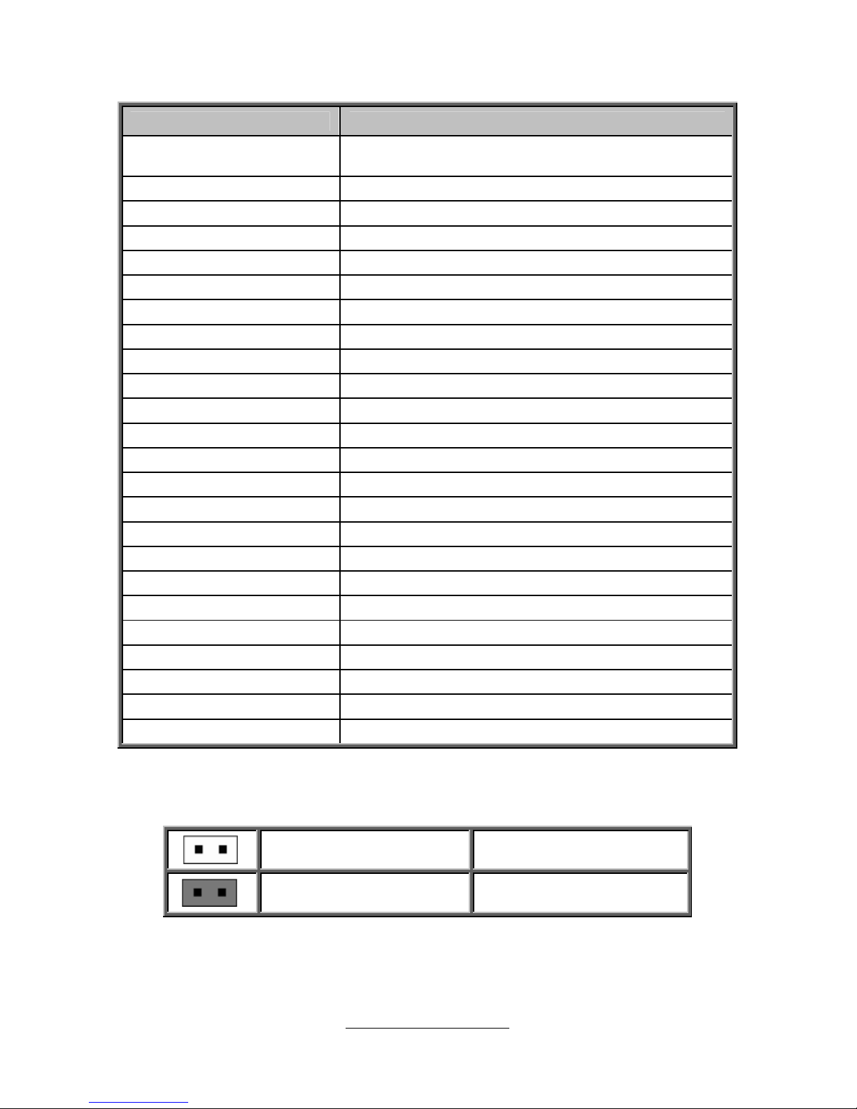
Jumpers & Connectors
Jumper/Connector Function
CPU0_FAN/CPU1_FAN/
SYS_FAN_1/2/3/4/5
4-pin Fan Connector
J15 BIOS Recovery Mode Jumper
J17 COM2 Header
J18/J19 COM Port Select Jumper
J22 Vertical Type-A USB Connector
J23 BMC Reset Jumper
J25/J26 USB Front Panel Connector
J29 PSMI Pin Header
J30 Front Panel Connector
J31 Front Panel ID LED
J32 Port 80 Debug Pin Header
J33 Chassis Intrusion Head er
J35 ID LED Switch Button
J79 ME Recovery Mode Jumper
J80 SMBUS HOST Pin Header
J196 MFG Jumper (reserved for ME F/W upgrade)
CLEAR_BTN1 Clear CMOS Reset Button
FAN_HDR1 Fan Connector Reserved for Barebone
IPMB1 IPMB Pin Header
KEY_1 Patsburg Upgrade ROM Module Header
SATA1/SATA2 SATA3.0 Connector
SATA3/4/5/6 SATA2.0 Connector
SGPIO2/SGPIO3/SGPIO4 PCH SGPIO Pin Header (reserved for barebone)
2PHD_1/2PHD_2 I350 LAN LED
Jumper Legend
OPEN - Jumper OFF
Without jumper cover
CLOSED - Jumper ON
With jumper cover
http://www.TYAN.com
22
SYS_FAN_1
CPU1_FAN
SYS_FAN_5
CPU0_FAN
SYS_FAN_2
SYS_FAN_3
SYS_FAN_4
J35
SATA1
SATA2
SATA3
SATA4
SATA5
FAN_HDR1
J22
http://www.TYAN.com
23
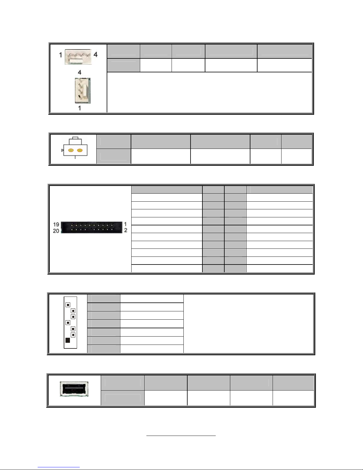
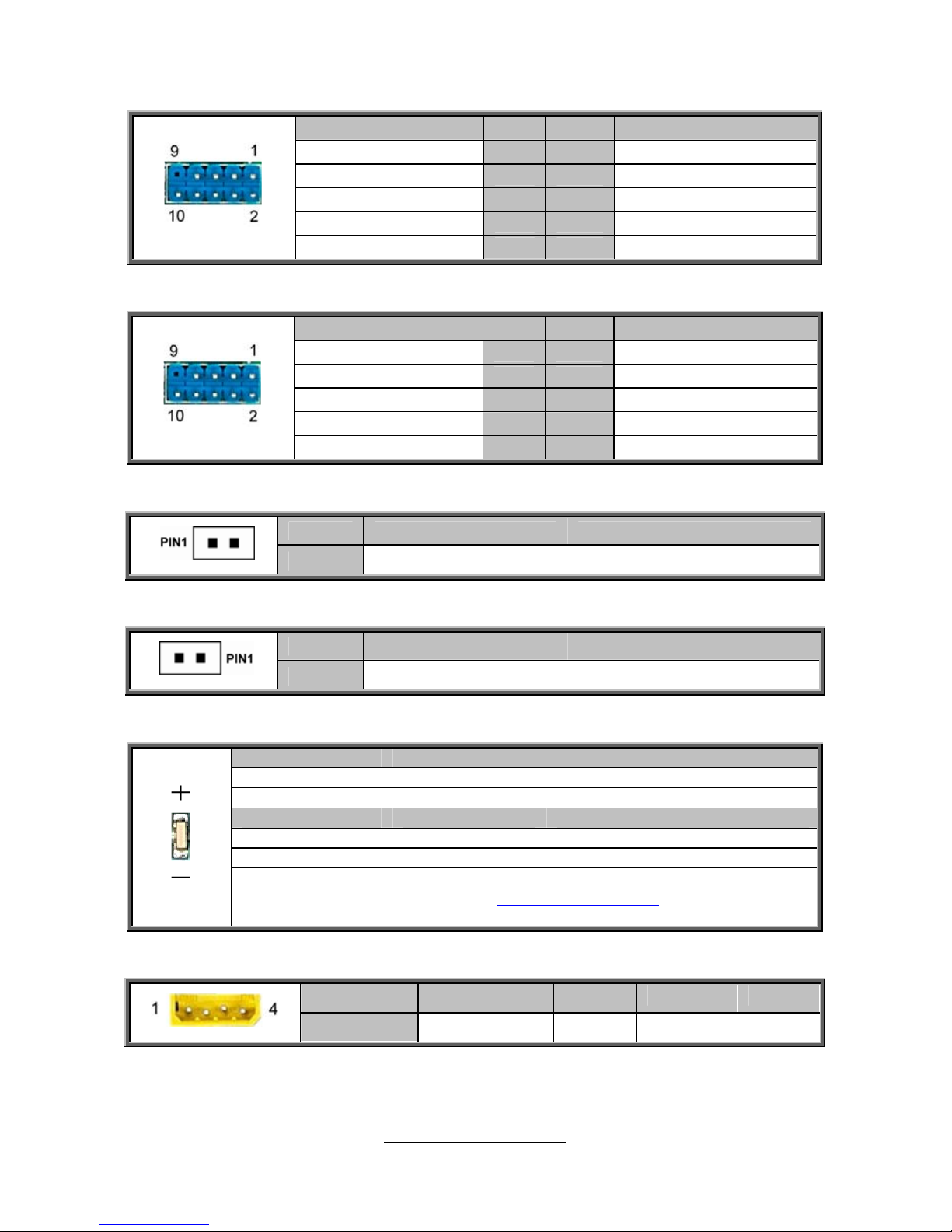
CPU0_FAN/CPU1_FAN/SYS_FAN_1/2/3/4/5: 4-Pin FAN Connector
Pin 1 2 3 4
Signal GND P12V FAN_TACH FAN_PWM
Use this header to connect the cooling fan to your motherboard to
keep the system stable and reliable.
J35: ID LED Switch Button
Pin 1 2 3 4
Signal FP_IDLEDSW# GND GND GND
FAN_HDR1: Fan Connector Reserved for Barebone
Signal Pin Pin Signal
BMC_FAN_TACH_2 1 2 BMC_FAN_TACH_7
BMC_FAN_TACH_3 3 4 BMC_FAN_TACH_8
BMC_FAN_TACH_4 5 6 FAN_T9
BMC_FAN_TACH_5 7 8 FAN_T10
BMC_FAN_TACH_6 9 10 FAN_T11
GND 11 12 NC
PWM4 13 14 PWM3
FAN_T12 15 16 FAN_SDA
FAN_T13 17 18 FAN_SCK
PWR 19 20 PWM5
SATA1~SATA6: 7-pin SATA Connector
1 GND
2 SATA TX DP
3 SATA TX DN
4 GND
5 SATA RX DN
6 SATA RX DP
7
1
7 GND
Connects to the Serial ATA ready
drives via the Serial ATA cable.
SATA1/SATA2: SATA3.0 Connector
SATA3/4/5/6: SATA2.0 Connector
J22: Vertical (Type A) USB Connectors
Pin 1 2 3 4
Signal VCC D- D+ GND
http://www.TYAN.com
24
J15
J17
J23
J18
J19
J29
http://www.TYAN.com
25
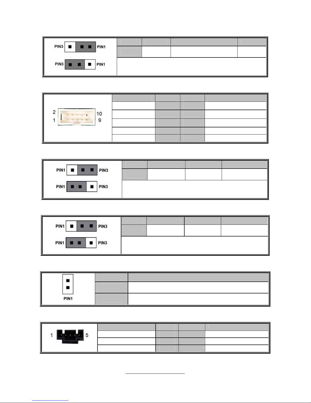
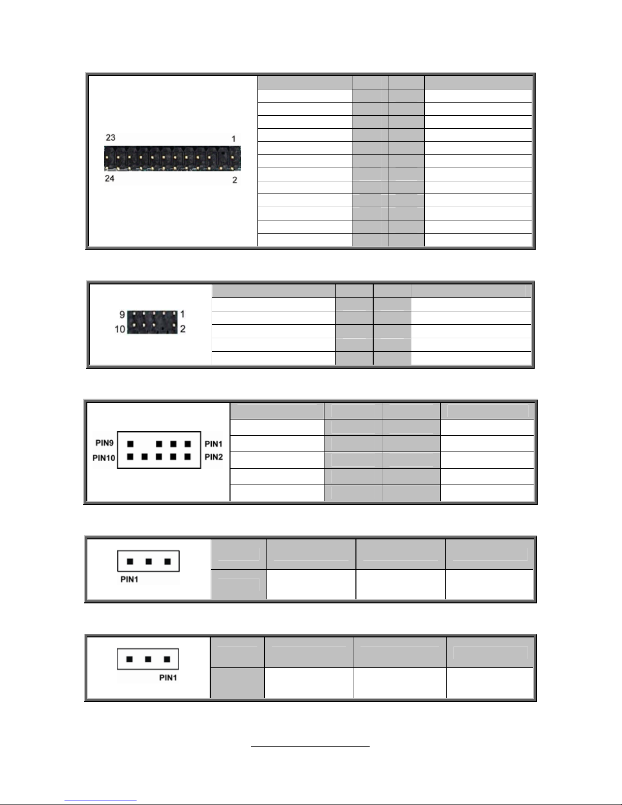
J15: BIOS Recovery Mode Jumper
Pin 1 2 3
Signal
OPEN FM_BIOS_RCVR_BOOT# GND
Pin1-2 closed: Normal (Default)
Pin2-3 closed: BIOS Recovery Mode
J17: COM2 Pin Header
Signal Pin Pin Signal
COM_DCD
1 2
COM_DSR
COM_RDX
3 4
COM_RTS
COM_TXD
5 6
COM_CTS
COM_DTR
7 8
COM_NRI
COM_RDX
9 10
NC
J18: COM Port Select Jumper
Pin 1 2 3
Signal
RX_D1 RXD-R RX_D5
Pin1-2 closed: COM2 (Default)
Pin2-3 closed: COM2 BMC Debug Port
J19: COM Port Select Jumper
Pin 1 2 3
Signal
TX_D1 TXD-R TX_D5
Pin1-2 closed: COM2 (Default)
Pin2-3 closed: COM2 BMC Debug Port
J23: BMC Reset Jumper
Pin Signal
1
BMC_JP_N
2
GND
J29: PSMI Pin Header
Signal Pin Pin Signal
BMC_PSMI_CLK 1 2 BMC_PSMI_DAT
PSU_SMBALERT_N 3 4 GND
NC 5
http://www.TYAN.com
26
J33
ID_LED1
IPMB1
J26/J25
J31
http://www.TYAN.com
27
J25: USB Front Panel Header
Signal Pin Pin Signal
+5VPWR 1 2 +5VPWR
USB3- 3 4 USB9-
USB3+ 5 6 USB9+
GND 7 8 GND
KEY
9 10 NC
J26: USB Front Panel Header
Signal Pin Pin Signal
+5VPWR 1 2 +5VPWR
USB2- 3 4 USB8-
USB2+ 5 6 USB8+
GND 7 8 GND
KEY
9 10 NC
J31: Front Panel ID LED
Pin 1 2
Signal FP_IDLEDSW# GND
J33: Chassis Intrusion Header
Pin 1 2
Signal INTRUDER_L GND
ID_LED1: ID LED
Pin Signal
+ P3V3_AUX
- ID_SW_L
State Color Description
On Blue System identified
Off Off System not identified
NOTE: IPMI can activate ID LED from remote site.
Please visit the TYAN Web Site at http://www.tyan.com
to download the
latest AST2300 Software Configuration Guide for IPMI settings.
IPMB1: IPMB Pin Header
Pin
1 2 3 4
Signal
IPMB DATA GND IPMB CLK NC
http://www.TYAN.com
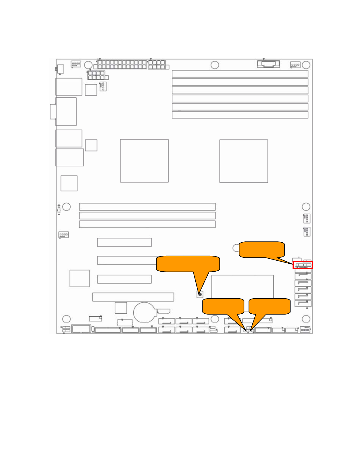
28
J30
J80
J32
KEY_1
SGPIO2SGPIO4 SGPIO3
http://www.TYAN.com
29
J30: Front Panel Connector
Signal Pin Pin Signal
PW_LED+ 1 2 FP_PWR
KEY 3 4 IDLED+
PW_LED- 5 6 IDLEDHD_LED+ 7 8 WARN_LED
HD_LED- 9 10 PSU_ALERT-
PWR_SW 11 12 LAN1_LED+
GND 13 14 LAN1_LED-
RST_SW 15 16 SDA
GND 17 18 SCL
ID_SW 19 20 INTRUDER_L
TEMP 21 22 LAN2_LED+
NMI_SW 23 24 LAN2_LED-
J32: Port80 Debug Pin Header
Signal Pin Pin Signal
VCC3 1 2 FRAME#
LPC_AD0 3 4 KEY
LPC_AD1 5 6 PLT_RST#
LPC_AD2 7 8 GND
LPC_AD3 8 10 CLK_33M
SGPIO2/3/4: PCH SGPIO Pin Header (reserved for barebone)
Signal Pin Pin Signal
SM_CLK 1 2 SD_IN
CM_DATA 3 4 SD_OUT
GND 5 6 S_LOAD
KEY 7 8 S_CLK
+3VPWR 9 10 ERR_LED
J80: SMBus Host Pin Header
Pin 1 2 3
Signal SMB_CLK GND SMB_DAT
KEY_1: PCH Upgrade ROM Module Header
Pin 1 2 3
Signal GND PCH_SKU_KEY GND
http://www.TYAN.com
30
J79/J196
CLEAR_BTN1
2PHD_1 2PHD_2
 Loading...