

TYAN S7020 User Manual

http://www.tyan.com
1
S7020
Version 1.0
Copyright
Copyright © 2009 MiTAC International Corporation. All rights reserved. TYAN® is a
registered trademark of MiTAC International Corporation.
Trademark
All registered and unregistered trademarks and company names contained in this
manual are property of their respective owners including, but not limited to the
following.
TYAN
®
is a trademark of MiTAC International Corporation.
Intel
®
5500 Series and combinations thereof are trademarks of Intel Corporation.
AMI, AMI BIOS are trademarks of AMI Technologies.
Microsoft, Windows are trademarks of Microsoft Corporation.
SuSE is a trademark of Novell.
IBM, PC, AT, and PS/2 are trademarks of IBM Corporation.
Notice
Information contained in this document is furnished by MiTAC International
Corporation and has been reviewed for accuracy and reliability prior to printing.
MiTAC assumes no liability whatsoever, and disclaims any express or implied
warranty, relating to sale and/or use of TYAN products including liability or
warranties relating to fitness for a particular purpose or merchantability. MiTAC
retains the right to make changes to product descriptions and/or specifications at
any time, without notice. In no event will MiTAC be held liable for any direct or
indirect, incidental or consequential damage, loss of use, loss of data or other
malady resulting from errors or inaccuracies of information contained in this
document.

2
http://www.tyan.com
Table of Contents
Before You Begin .................................................................................................. 3
Chapter 1: Instruction............................................................................................. 5
1.1 Congratulations ............................................................................................. 5
1.2 Hardware Specifications................................................................................ 5
1.3 AST2050 ....................................................................................................... 7
Chapter 2: Board Installation................................................................................. 9
2.1 Board Image................................................................................................ 10
2.2 Block Diagram............................................................................................. 11
2.3 Board Parts, Jumpers and Connectors .......................................................13
2.4 Installing the Processor and Heat Sink........................................................ 24
2.5 Thermal Interface Material .......................................................................... 26
2.6 Finishing Installing the Heat Sink ............................................................... 27
2.7 Tips on Installing Motherboard in Chassis................................................... 28
2.8 Installing the Memory .................................................................................. 29
2.9 Attaching Drive Cables................................................................................ 33
2.10 Installing Add-In Cards .............................................................................. 34
2.11 Installing I/O Shield ................................................................................... 35
2.12 Connecting External Devices .................................................................... 36
2.13 Installing the Power Supply ....................................................................... 37
2.14 Finishing up............................................................................................... 37
Chapter 3: BIOS Setup ......................................................................................... 39
3.1 BIOS Main Menu......................................................................................... 41
3.2 Advanced Menu .......................................................................................... 42
3.3 PCI PnP Menu............................................................................................. 70
3.4 Boot Menu................................................................................................... 72
3.5 Security Menu ............................................................................................. 77
3.6 Chipset Menu .............................................................................................. 78
3.7 Exit Menu .................................................................................................... 84
Chapter 4: Diagnostics......................................................................................... 85
4.1 Beep Codes ................................................................................................ 85
4.2 Flash Utility.................................................................................................. 85
4.3 AMIBIOS Post Code.................................................................................... 86
Glossary ................................................................................................................ 89
Technical Support ................................................................................................95
3
http://www.tyan.com
Before You Begin…
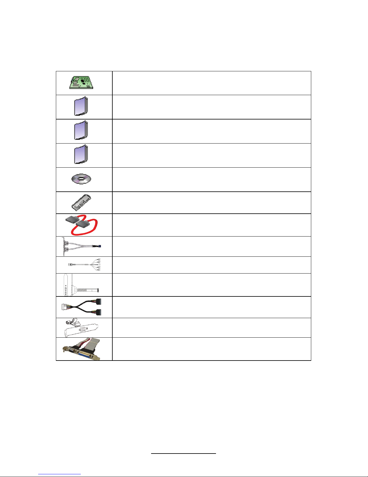
Check the box contents!
1x S7020 motherboard
1 x S7020 user’s manual
1 x S7020 Quick Reference guide
1 x IO Shield Installation guide
1 x TYAN driver CD
1 x I/O shield
6 x Serial ATA Cable
1 x USB2.0 cable
2 x mini SAS Cable (for S7020WAGM2NR only)
1 x Audio cable (optional, P/N # 422774700001)
3 x Serial ATA power cable (optional)
1x Serial Port Cable (optional)
1 x LPT-COM port bracket (optional)
If any of these items are missing, please contact your vendor/dealer for
replacement before continuing with the installation process.
NOTE: Please contact your vendor for optional cables purchase.

4
http://www.tyan.com
NOTE

5
http://www.tyan.com
Chapter 1: Instruction
1.1 Congratulations
You have purchased one of the most powerful server solutions. Based on Intel
®
5520 (36D) and Intel
®
ICH10/R chipsets, the S7020 is designed to support up to
two Nehalem-EP 5500 Series processors and up to 96GB DDR3-800/1066/1333
memory, providing a rich feature set and incredible performance. Leveraging
advanced technology from Intel, the S7020 is capable of offering scalable 32 and
64-bit computing, high-bandwidth memory design, and lightning-fast PCI-E bus
implementation.
The S7020 not only empowers your company in today’s demanding IT environment
but also offers a smooth path for future application usage. All of this provides the
S7020 the power and flexibility to meet the needs of nearly any server application.
Remember to visit TYAN’s Website at http://www.tyan.com. There you can find
information on all of TYAN’s products with FAQs, online manuals and BIOS
upgrades.
1.2 Hardware Specifications
TYAN S7020 (S7020WAGM2NR)
Supported CPU
Series
Intel Xeon Processor 5500 Series
Socket Type /
Q’ty
LGA1366 / (2)
Processor
Thermal Design
Power (TDP)
wattage
130W
IOH / ICH Intel 5520 / ICH10R
Super I/O Winbond W83627DHG
Chipset
PCI-X bridge Intel 6702PXH-V
Supported DIMM
Qty
(12) DIMM sockets
DIMM Type /
Speed
DDR3 800/1066/1333 RDIMM/UDIMM
Capacity Up to 96GB w/ dual rank RDIMMs
Memory channel 6 Channels (3 Channels per CPU)
Memory
Memory voltage 1.5V
PCI-E
(1) PCI-E x8 slot (w/ x4 link) / (1) PCI-E Gen.2 x16 slot /
(1) PCI-E Gen.2 x8 slot
Expansion
Slots
PCI-X (2) PCI-X 64-bit 133/100MHz slots
6
http://www.tyan.com
Port Q’ty (2)
LAN
Controller Intel 82574L
Connector (2) Mini-SAS connectors (support total 8 ports)
Controller LSI SAS1068E
Speed 3.0 Gb/s
SAS
RAID RAID 0/1/1E (LSI Integrated RAID)
Connector (6) SATA
Controller ICH10R
Speed 3.0 Gb/s
Storage
SATA
RAID RAID 0/1/10/5 (Intel Matrix RAID)
Connector type D-Sub 15-pin
Resolution 1600x1200@60Hz
Graphic
Chipset Aspeed AST2050
Chipset Realtek ALC262
Audio
Feature HDA 2.0 spec compliant (pin header only)
USB
(9) USB2.0 ports (4 at rear, 4 via cable, 1 type A
onboard)
COM (2) ports (1 at rear, 1 via cable)
SAS (2) Mini-SAS (4-in-1) connectors
VGA (1) D-Sub 15-pin VGA port
Audio
(1) CD_IN header / (1) 2x5-pin front panel audio header /
(1) 2x6-pin rear audio jack header
RJ-45 (2) GbE ports
LPT (1) LPT header
Power SSI 24-pin + 8-pin + 8-pin power connectors / EPS12V
Front Panel (1) 2x12-pin SSI front panel header
FDD (1) FDD connector
Input /Output
SATA (6) SATA-II connectors
Chipset Winbond W83793G
Voltage
Monitors voltage for CPU, memory, chipset & power
supply
Fan Total (5) 4-pin headers / Total (5) 8-pin headers
Temperature Monitors temperature for CPU & system environment
System
Monitoring
Others Chassis intrusion detection / Watchdog timer support
Onboard Chipset Onboard Aspeed AST2050
AST2050 IPMI
Feature
IPMI 2.0 compliant baseboard management controller
(BMC) / Supports storage over IP and remote platformflash/ BIOS update / USB 2.0 virtual hub
Server
Management
AST2050 iKVM
Feature
24-bit high quality video compression / Dual 10/100 Mb/s
MAC interfaces
Brand / ROM size AMI / 4MB
BIOS
Feature
Plug and Play (PnP) /PCI2.3 /WfM2.0 /SMBIOS2.3 /PXE
boot / ACPI 2.0 power management /Power on mode
after power recovery / User-configurable H/W monitoring

7
http://www.tyan.com
/ Auto-configurable of hard disk types / Multiple boot
options
Form Factor SSI EEB
Form Factor
Board Dimension 12”x13” (305x330mm)
Operating
System
OS supported list
Please refer to our web site for the OS supported list.
http://www.tyan.com/tech/os_support1.aspx
FCC (DoC) Class B
Regulation
CE (DoC) Yes
Operating Temp. 10° C ~ 35° C (50° F~ 95° F)
Non-operating
Temp.
- 40° C ~ 70° C (-40° F ~ 158° F)
Operating
Environment
In/Non-operating
Humidity
90%, non-condensing at 35° C
RoHS
RoHS 6/6
Complaint
Yes
Motherboard (1) S7020 Motherboard
Manual
(1) User’s manual / (1) Quick Ref. Guide / (1) IO Shield
Installation Guide
Installation CD (1) TYAN installation CD
I/O Shield (1) I/O Shield
SATA (6) SATA signal cables
SAS
(2) Mini-SAS (2x SFF-8470) cables (only for
S7020WAGM2NR)
Package
Contains
Cable
USB (1) CCBL-035J, 2-port USB bracket cable
Optional
accessories
for future
upgrade
Cable
(1) CCBL-0615, COM port bracket cable / (1) CCBL0311, SATA 1-to-2 power cable / (1) CCBL-035J, 2-port
USB bracket cable / (1) CCBL-0613, 3-POS audio
bracket cable / (1) LPT-COM port bracket cable
1.3 AST2050
Please visit the TYAN Web Site at http://www.tyan.com to download the latest
AST2050 User’s Guide.

8
http://www.tyan.com
NOTE

9
http://www.tyan.com
Chapter 2: Board Installation
You are now ready to install your motherboard. The mounting hole pattern of the
S7020 matches the SSI EEB specification. Before continuing with installation,
confirm that your chassis supports an SSI EEB motherboard.
How to install our products right… the first time
The first thing you should do is reading this user’s manual. It contains important
information that will make configuration and setup much easier. Here are some
precautions you should take when installing your motherboard:
Ground yourself properly before removing your motherboard from the antistatic
bag. Unplug the power from your computer power supply and then touch a
safely grounded object to release static charge (i.e. power supply case). For
the safest conditions, TYAN recommends wearing a static safety wrist strap.
Hold the motherboard by its edges and do not touch the bottom of the board, or
flex the board in any way.
Avoid touching the motherboard components, IC chips, connectors, memory
modules, and leads.
Place the motherboard on a grounded antistatic surface or on the antistatic bag
that the board was shipped in.
Inspect the board for damage.
The following pages include details on how to install your motherboard into your
chassis, as well as installing the processor, memory, disk drives and cables.
NOTE
DO NOT APPLY POWER TO THE BOARD IF IT HAS BEEN
DAMAGED.
10
http://www.tyan.com
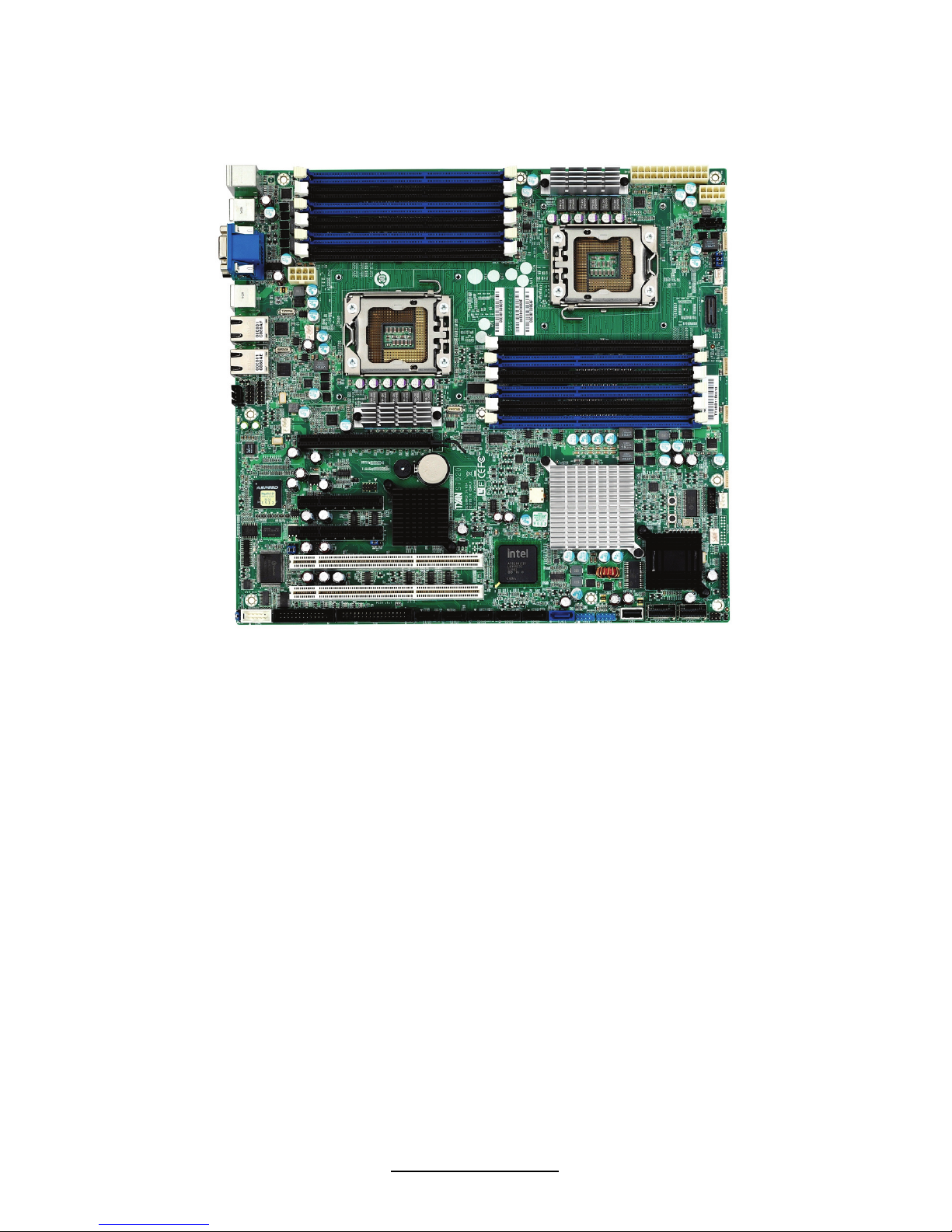
2.1 Board Image
S7020
This picture is representative of the latest board revision available at the time of
publishing. The board you receive may or may not look exactly like the above
picture.
11
http://www.tyan.com
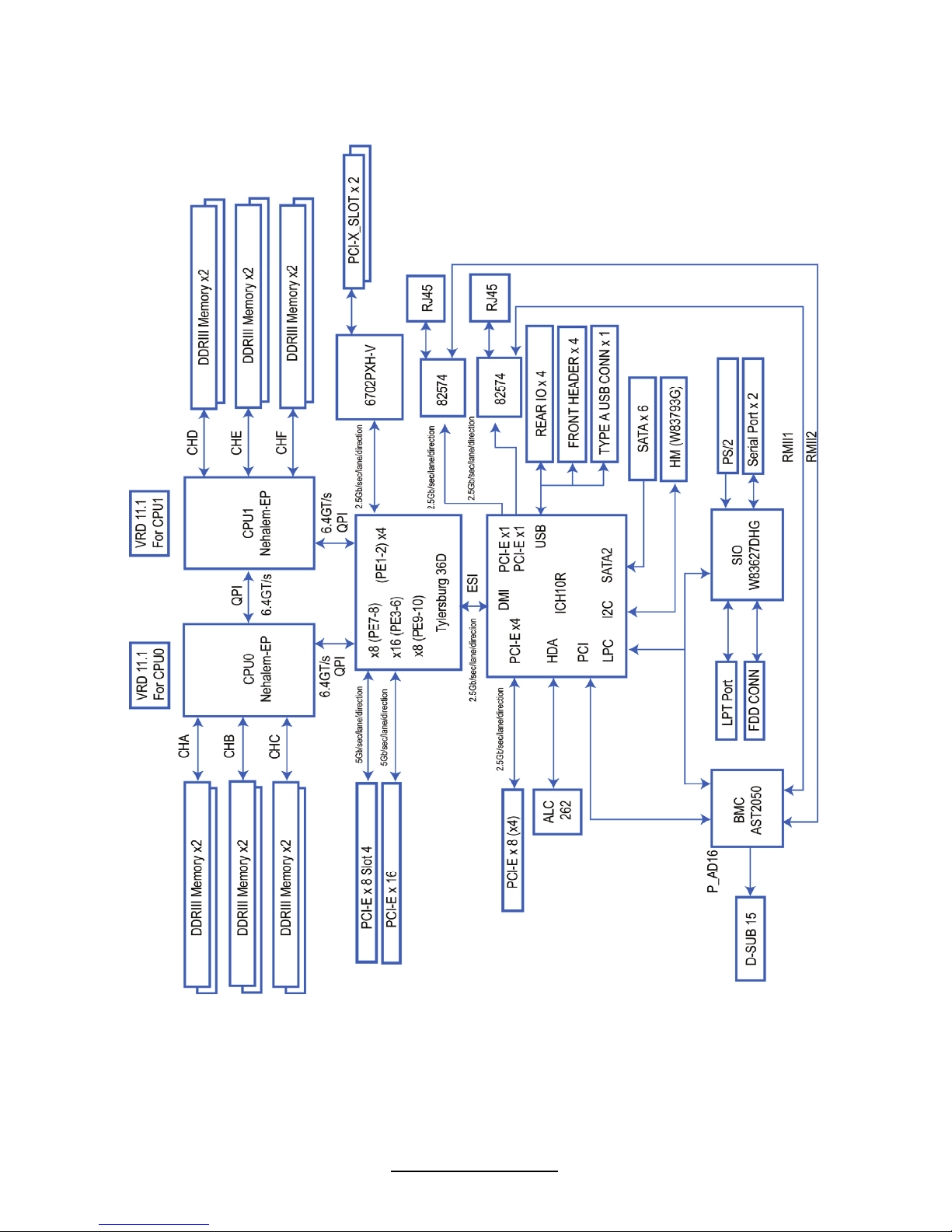
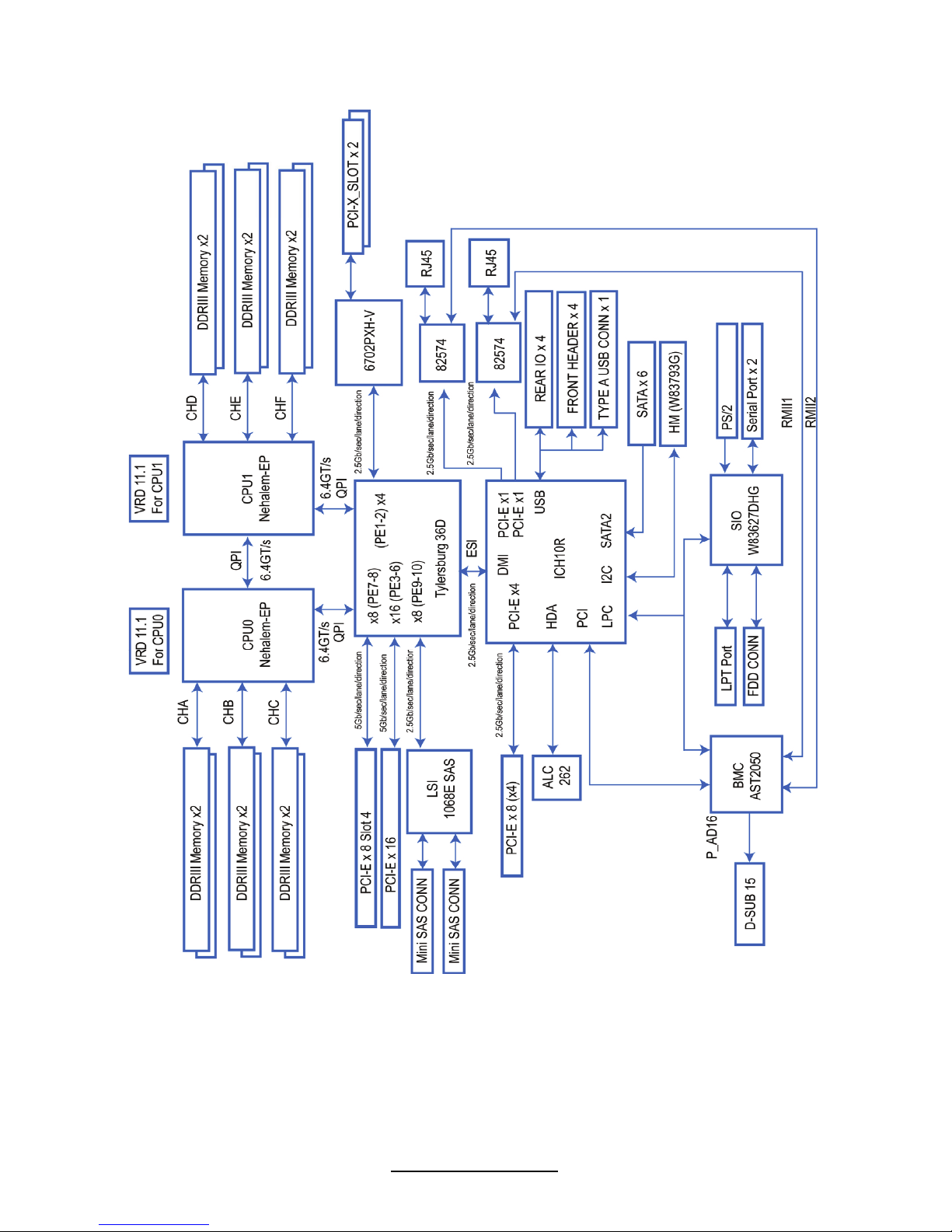
2.2 Block Diagram
S7020AGM2NR
12
http://www.tyan.com
S7020WAGM2NR
13
http://www.tyan.com
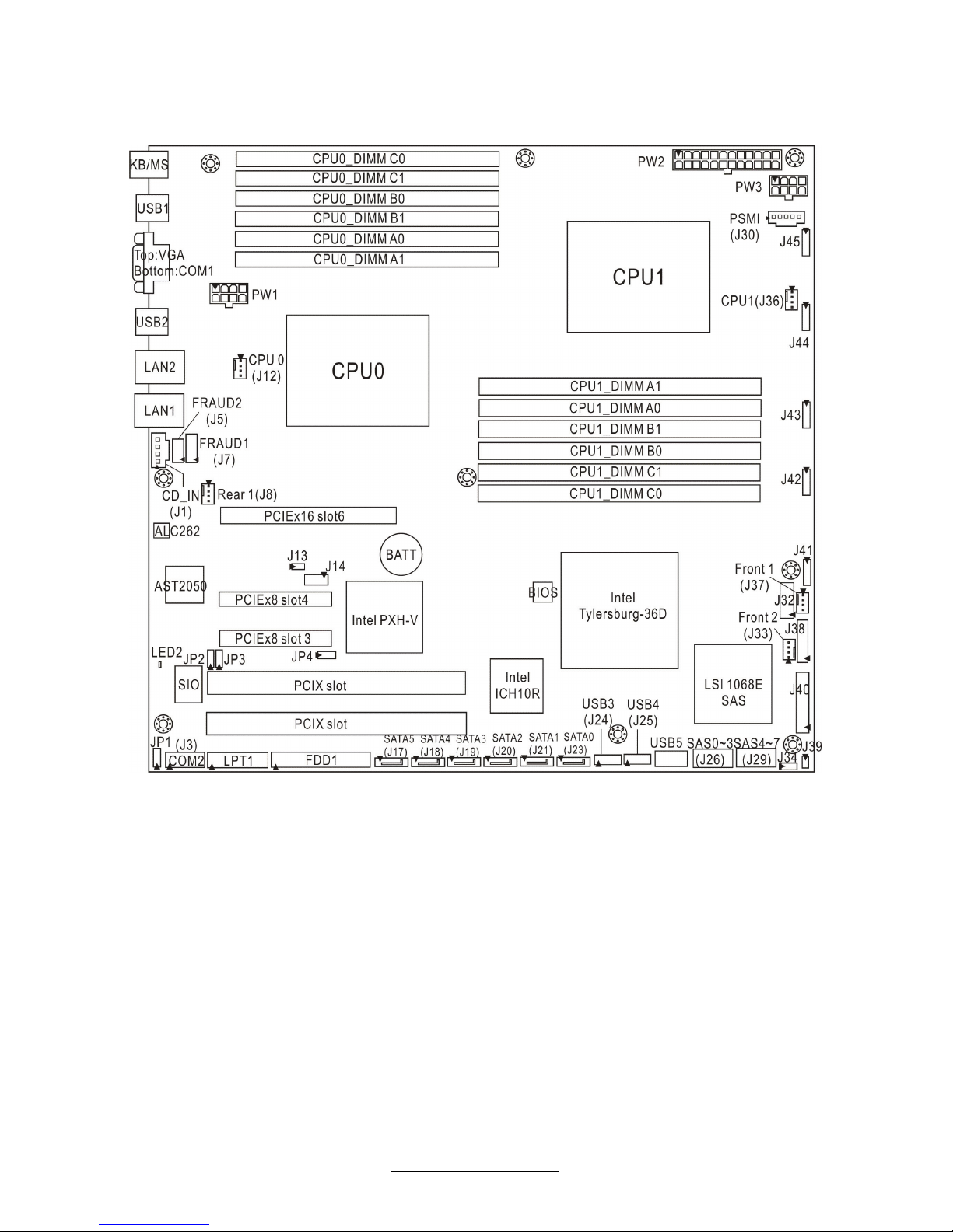
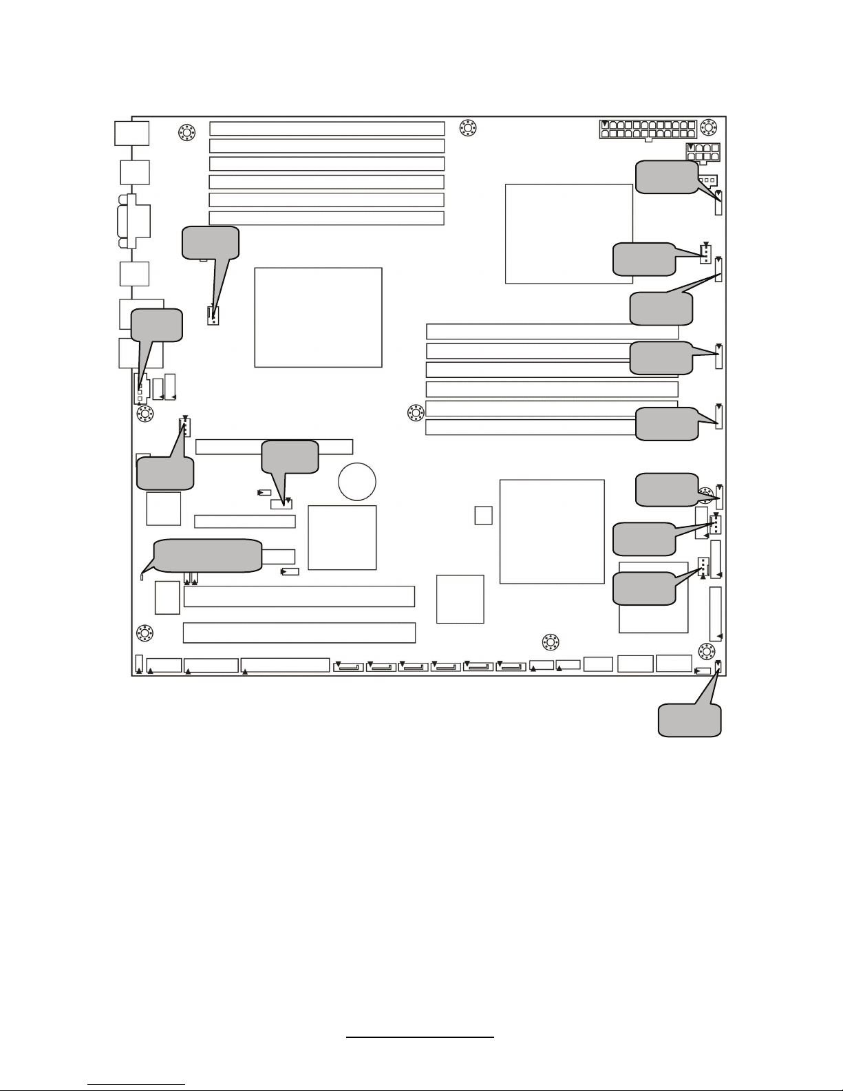
2.3 Board Parts, Jumpers and Connectors
S7020WAGM2NR
This diagram is representative of the latest board revision available at the time of
publishing. The board you receive may not look exactly like the above diagram.
14
http://www.tyan.com
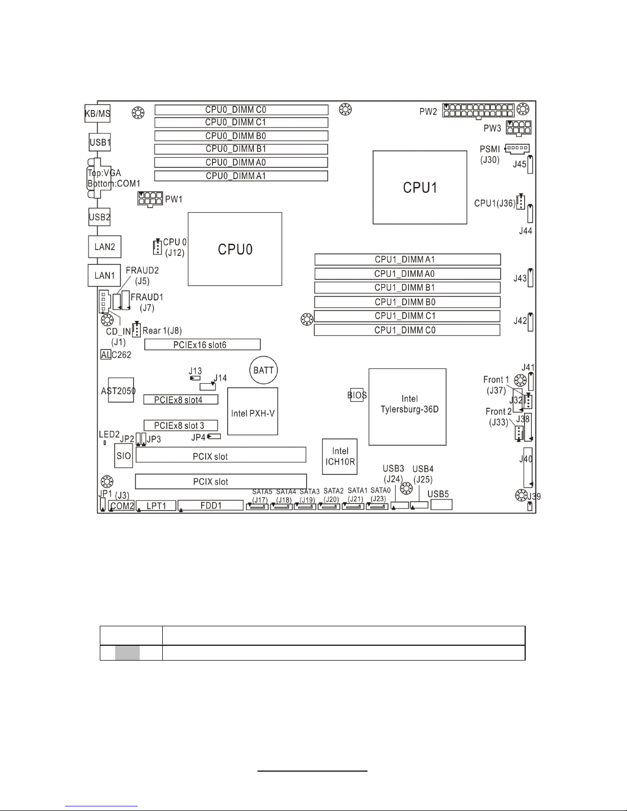
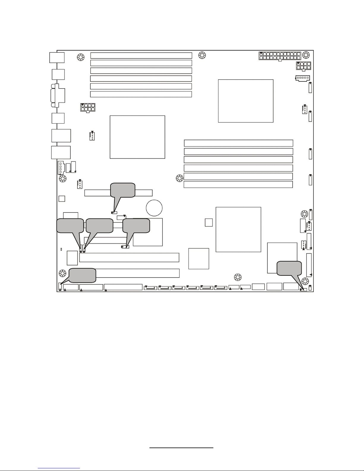
S7020AGM2NR
Jumper Legend
OPEN - Jumper OFF, without jumper cover
CLOSED – Jumper ON, with jumper cover
15
http://www.tyan.com
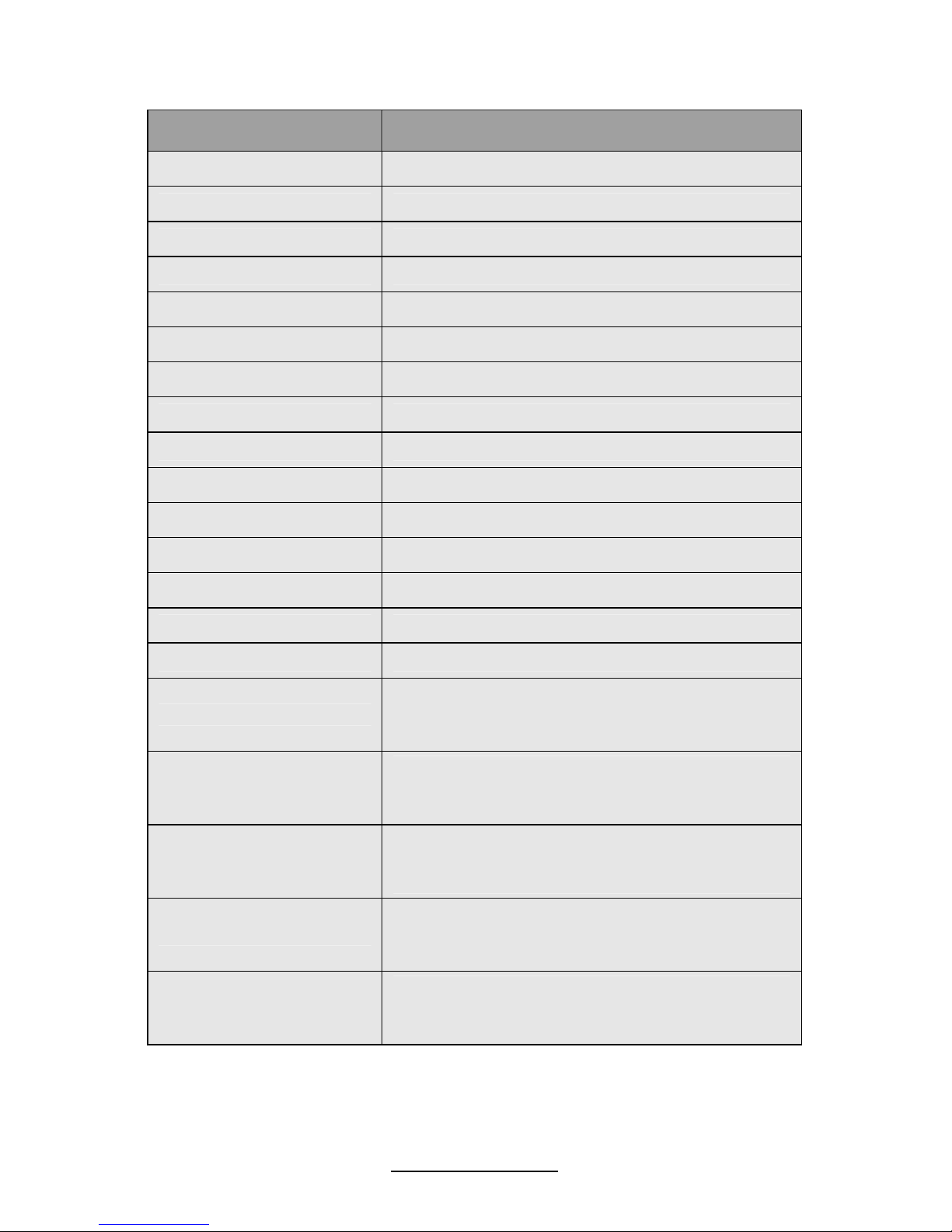
Jumper/Connector Function
J40 Front Panel Connector
J24/J25 USB Front Panel Header (blue)
J3 COM2 Connector
J14 Port 80 Header
J39 Chassis Intrusion Header
J5 Intel HD Audio Header
J7 Specific Definition Audio Header
USB5 Type-A USB Connector
J1 CD_IN Connector
J30 PSMI Connector
J32 ICH SGPIO Header
J38 BB Fan Header (reserved for Barebone)
J41/J42/J43/J44/J45 8-pin 4056 Fan Connector
J8/J12/J33/J36/J37 4-pin Fan Connector
LED2 BMC LED
J13
BMC Reset Jumper
NC: Default
Pin 1-2 closed: Disable BMC
JP1
Clear CMOS Jumper
Pin 1-2 closed: Normal (Default)
Pin 2-3 closed: Clear
JP2/JP3
COM2 Switch Jumper
Pin 1-2 closed: SIO to COM2 (Default)
Pin 2-3 closed: BMC UART2 to COM2
J34
SAS Enable/Disable Jumper
Pin 1-2 closed: Enable (Default)
Pin 2-3 closed: Disable
JP4
PCIX Frequency Select Jumper
Pin 1-2 closed: 133MHz (Default)
Pin 2-3 closed: 100MHz
16
http://www.tyan.com
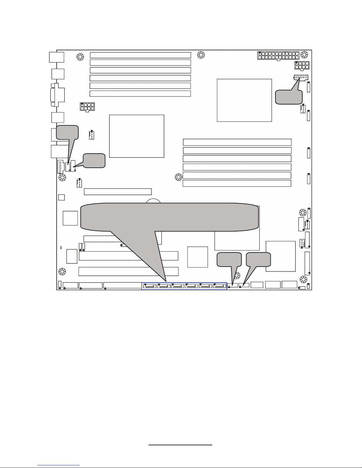
J24 J25
J5
J7
(from left to right)
SATA5/SATA4/SATA3/SATA2/SATA1/SATA0
J30
17
http://www.tyan.com
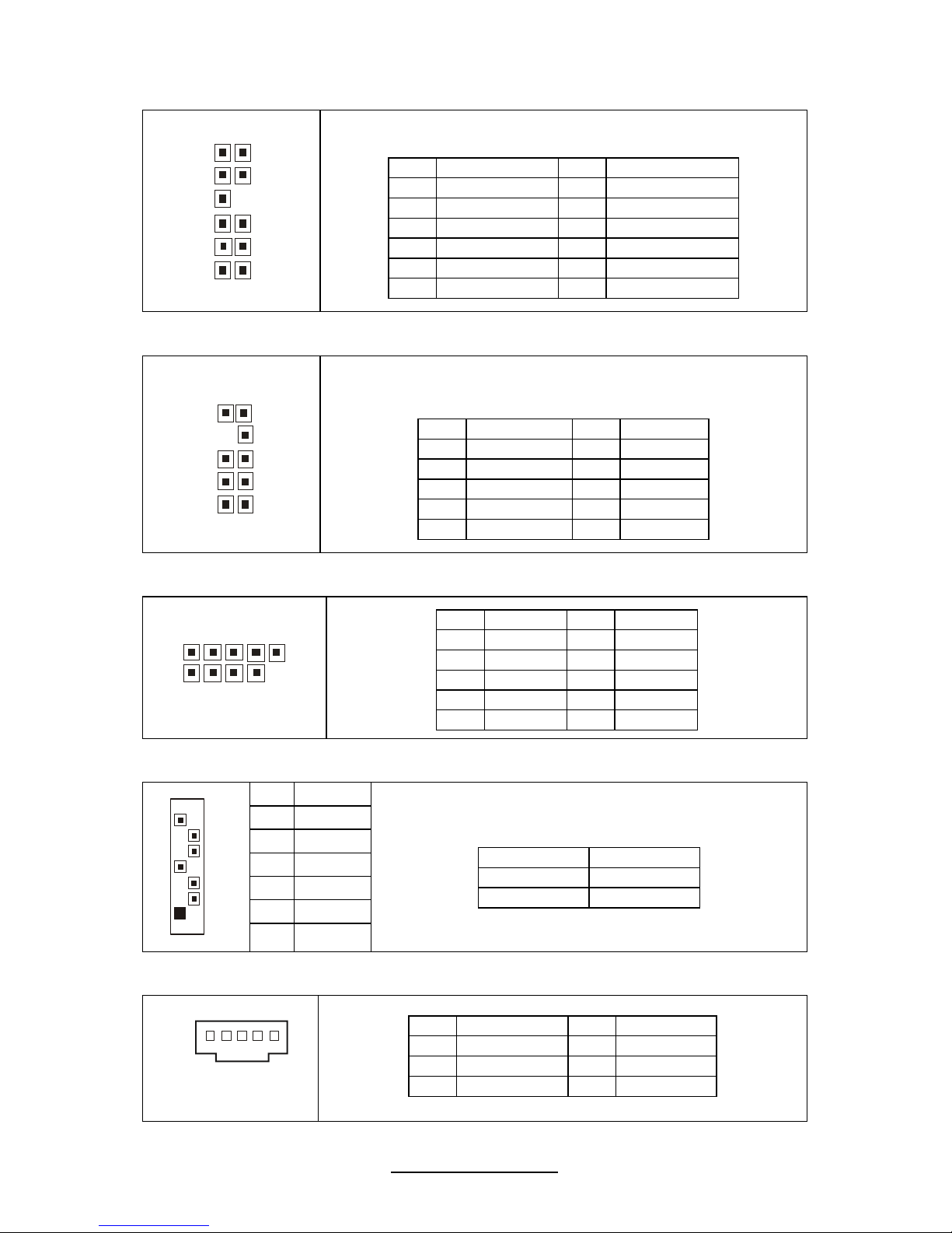
FPAUD1 (J7): Specific Definition Audio Header
1112
2
1
TYAN does not provide cables for this header.
Pin Signal Pin Signal
1 MIC_L_IN 2 MIC_R_IN
3 GND 4 MIC_JD
5 LINE_IN_L 6 LINE_IN_R
7 KEY 8 LINE_IN_JD
9 LINE_OUT_L 10 LINE_OUT_R
11 NC 12 LINE_OUT_JD
FPAUD2 (J5): Intel HD Audio Header
10
2
9
1
TYAN does not provide cables for this header.
Pin Signal Pin Signal
1 MIC_L_IN 2 GND
3 MIC_R_IN 4 NC
5 LINE_R_IN 6 MIC_JD
7 I/O SENSE 8 KEY
9 LINE_L_IN 10 LINE_JD
J24/J25: USB Front Panel Header (Blue)
10
9
2
1
Pin Signal Pin Signal
1 +5V 2 +5V
3 USB D- 4 USB D5 USB D+ 6 USB D+
7 GND 8 GND
9 KEY 10 GND
SATA0/1/2/3/4/5: Serial ATA Connector
7 GND
6 RXP
5 RXN
4 GND
3 TXN
2 TXP
7
1
1 GND
Connects to the Serial ATA ready drives via the
Serial ATA cable.
SATA0: J23 SATA1: J21
SATA2: J20 SATA3: J19
SATA4: J18 SATA5: J17
J30: PSMI Connector
1
Pin Signal Pin Signal
1 SMB_CLK 2 SMB_DAT
3 SMBALERT 4 GND
5 V3P3
18
http://www.tyan.com
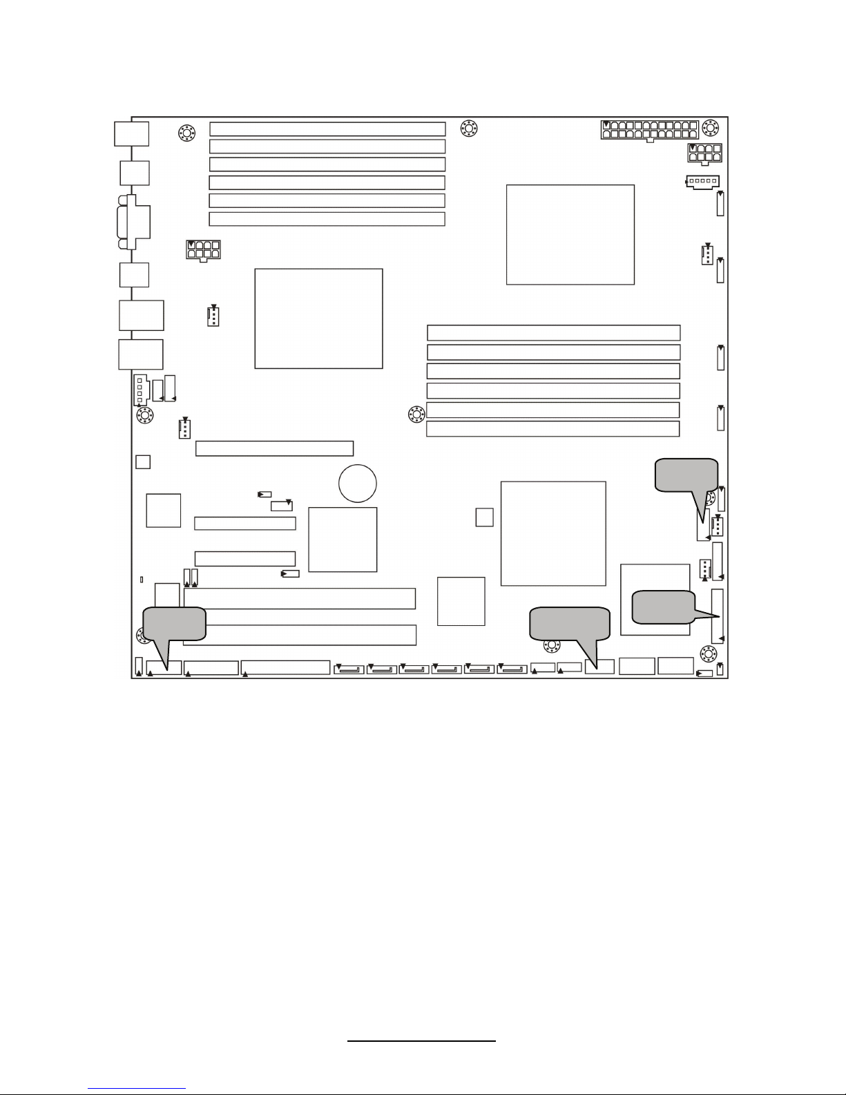
J3
J32
USB5
J40
19
http://www.tyan.com
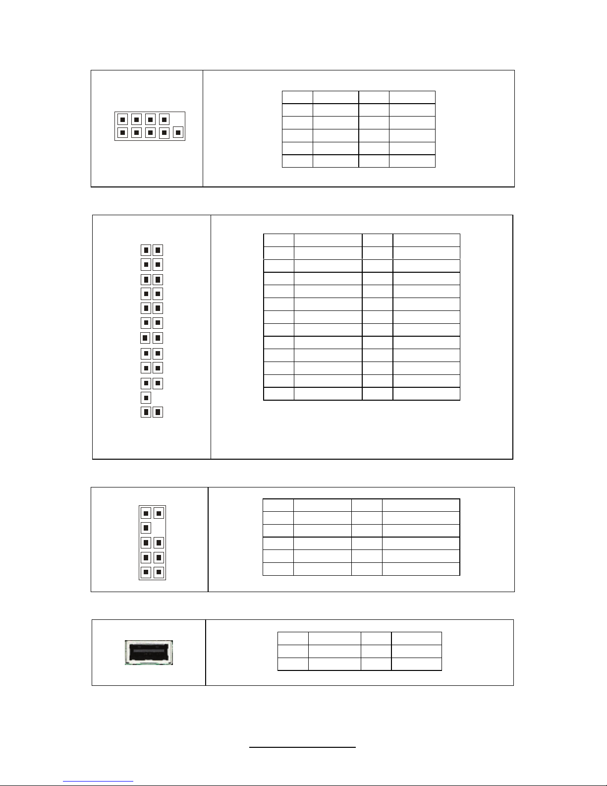
J3: COM2 Connector
1
2
1
0
9
Pin Signal Pin Signal
1 DCD 2 DSR
3 RXD 4 RTS
5 TXD 6 CTS
7 DTR 8 RI
9 GND 10 KEY
J40: Standard Front Panel Connector
2
4
2
1
23
NOTE1: +3.3V power rail is IDLED, WLED (Warning LED),
LANLED
NOTE2: +5V power rail is PWRLED, HDLED
Pin Signal Pin Signal
1 PWRLED+ 2 +3VSB
3 KEY 4 IDLED+
5 PWRLED- 6 IDLED7 HDLED+ 8 WLED9 HDLED- 10 WLED+
11 PWRSW+ 12 LAN1LED+
13 GND 14 LAN1LED15 RSTSW 16 SMBDAT
17 GND 18 SMBCLK
19 IDLED_SW 20 INTRD#
21 GND 22 LAN2LED+
23 NMI_SW- 24 LAN2LED-
J32: ICH SGPIO Header
1
029
1
Pin Signal Pin Signal
1 SMBCLK 2 SDATAOUT0
3 SMBDAT 4 SDATAOUT1
5 GND 6 SLOAD
7 KEY 8 SCLOCK
9 NC 10 NC
USB5: Type-A USB Connector
Pin Signal Pin Signal
1 +5v 2 USB D3 USB D+ 4 GND
20
http://www.tyan.com
J39
J36
J12
J37
J33
J8
J1
J45
J44
J43
J42
J41
J14
BMC LED
21
http://www.tyan.com
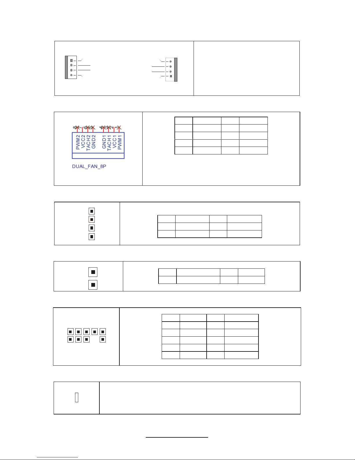
J8/J12/J33/J36/J37: 4-pin Fan Header
+12V
PWM Control
GND
Tachometer
1
+12V
PWM Control
GND
Tachometer
1
Use this header to connect the
cooling fan to your
motherboard to keep the
system at optimum
performance levels.
J41/J42/J43/J44/J45: 8-pin 4056 Fan Header
NOTE: Do not mix 8-pin Fan headers with 4-pin
Fan headers. Mix use of these fan headers will
cause problems to the system.
Pin Signal Pin Signal
1 PWM1 2 +12V
3 TACH1 4 GND
5 GND 6 TACH2
7 +12V 8 PWM2
J1: CD_IN Audio Header
1
4
TYAN does not provide cables for this header.
Pin Signal Pin Signal
1 CD_IN_L 2 GND
3 GND 4 CD_IN_R
J39: Chassis Intrusion Header
1
Pin Signal Pin Signal
1 INTRUDER# 2 GND
J14: PORT 80 Header
1
0
9
2
1
Pin Signal Pin Signal
1 +3.3V 2 FRAME
3 LAD0 4 KEY
5 LAD1 6 PLTRST
7 LAD2 8 GND
9 LAD3 10 CLK 33M
LED2: BMC LED
The ASPEED heatbeat LED indicates the ASPEED status.
Always on: BMC is going to boot up or not working
Blinking: BMC ready
OFF: S5 power down
22
http://www.tyan.com
J34
J13
JP2 JP3
JP1
JP4
23
http://www.tyan.com
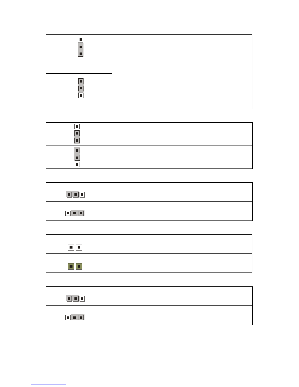
JP1: Clear CMOS Jumper
3
1
Normal
(Default)
3
1
Clear
Use this jumper when you forgot your system/setup
password or need to clear system BIOS setting.
How to clear the CMOS data
- Power off system and disconnect power
supply from AC source
- Use jumper cap to close Pin_2 and 3 for
several seconds to Clear CMOS
- Replace jumper cap to close Pin_1 and 2
Reconnect power supply to AC source
Power on system
JP2/JP3: COM2 Switch Jumper
3
1
Pin 1-2 Closed: SIO to COM2 (Default)
3
1
Pin 2-3 Closed: BMC UART2 to COM2
JP4: PCIX Frequency Select Jumper
3
1
Pin 1-2 Closed: PCIX 133MHz (Default)
1
3
Pin 2-3 Closed: PCIX 100MHz
J13: BMC Reset Jumper
1
NC: (Default)
1
Pin 1-2 Closed: Disable BMC
J34: SAS Enable/Disable Jumper (for S7020WAGM2NR only)
3
1
Pin 1-2 Closed: Enable (Default)
1
3
Pin 2-3 Closed: Disable
24
http://www.tyan.com
2.4 Installing the Processor and Heat Sink
Your S7020 supports the latest processor technologies from Intel
®
. Check the
TYAN website for latest processor support:
http://www.tyan.com
Processor Installation (LGA1366 Socket)
The processor should be installed carefully. Make sure you are wearing an antistatic
strap and handle the processor as little as possible. Please note that both
processors of the same type and frequency are required for optimal system
performance.
NOTE: TYAN is not liable for damage as a result of operating an unsupported
configuration.
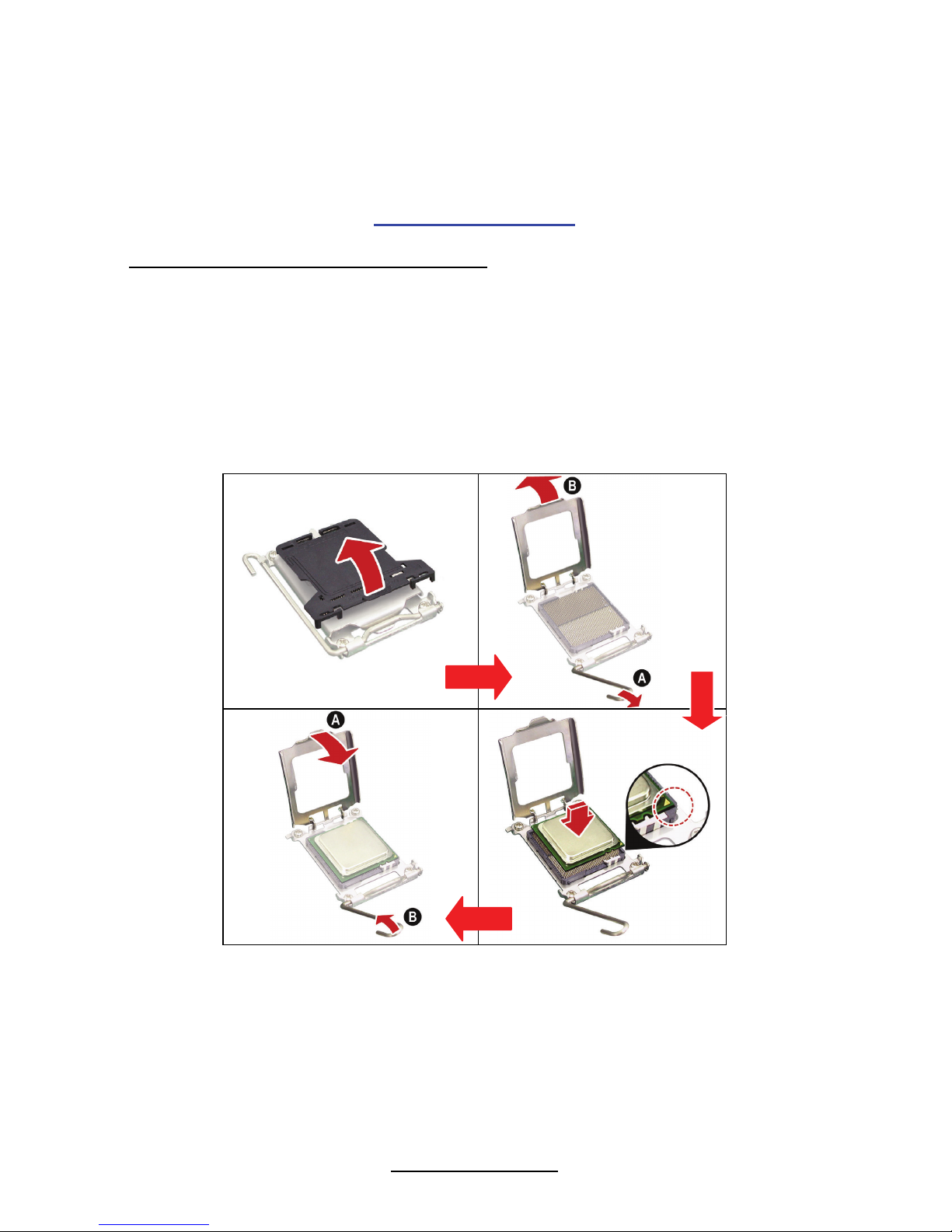
Follow these instructions to install your processor.
The diagram is provided as a visual guide to help you install the socket processor
and may not be an exact representation of the processor you have.
Step 1: Take off the CPU protection cap.
Step 2: Pull the CPU lever up to unlock the CPU socket (A). Then open the
socket in the direction as shown (B).
Step 3: Place the CPU on the CPU socket, ensuring that pin 1 is located in the
right direction.
25
http://www.tyan.com
Step 4: Close the CPU socket cover (A) and press the CPU socket lever down to
secure the CPU (B).
Take care when installing the processor as it has very fragile
connector pins below the processor that can bend and break
if inserted improperly.
Heat Sink Installation
After installing the processor, you should proceed to install the heat sink. The CPU
heat sink will ensure that the processor do not overheat and continue to operate at
maximum performance for as long as you own them. The overheated processor is
dangerous to the motherboard.
For the safest method of installation and information on choosing the appropriate
heat sink, using heat sinks validated by Intel
®
.
Please refer to Intel’s website at
www.Intel.com
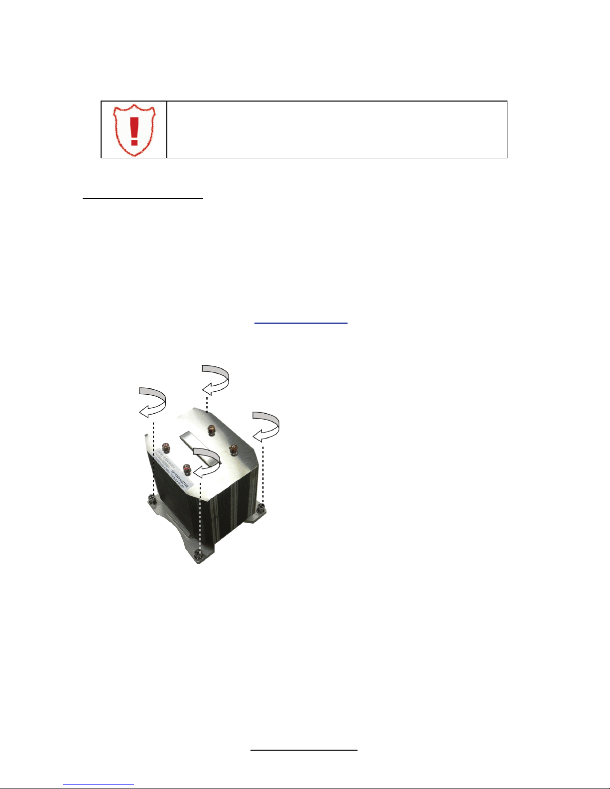
The following diagram illustrates how to install heat sink onto the CPU of S7020.
Place the heat sink on top of the
CPU and secure it to the
motherboard using four screws
clockwise.
26
http://www.tyan.com
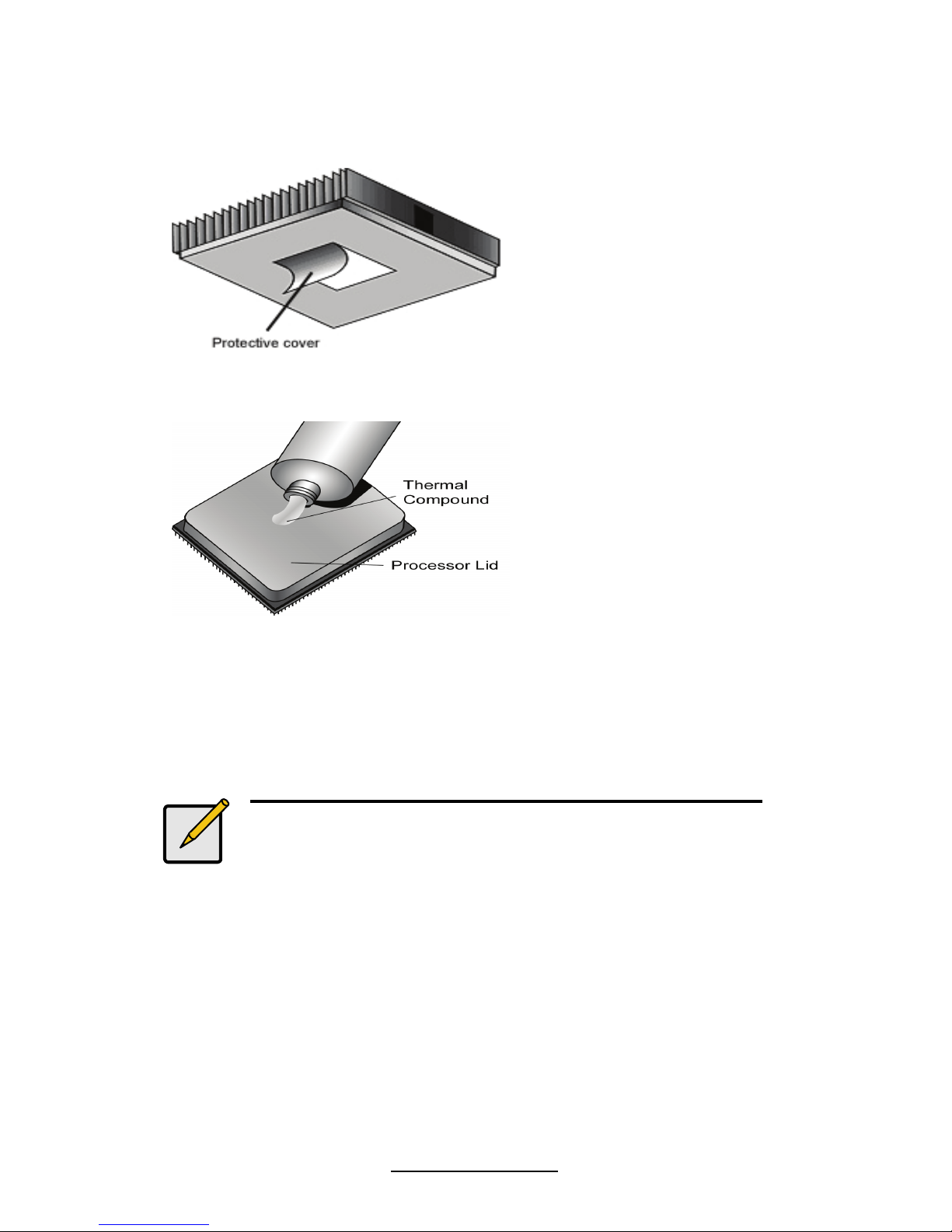
2.5 Thermal Interface Material
There are two types of
thermal interface materials
designed for use with the
processors.
The most common material
comes as a small pad
attached to the heat sink at
the time of purchase. There
should be a protective cover
over the material. Take care
not to touch this material.
Simply remove the protective
cover and place the heat
sink on the processor.
The second type of interface
material is usually packaged
separately. It is commonly
referred to as ‘thermal
compound’. Simply apply a
thin layer on to the CPU lid
(applying too much will
actually reduce the cooling).
Note:
Always check with the manufacturer of the heat sink &
processor to ensure the Thermal Interface material is
compatible with the processor & meets the
manufacturer’s warranty requirements.
27
http://www.tyan.com
2.6 Finishing Installing the Heat Sink
After you have finished installing the heat sink onto the processor and socket,
attach the end wire of the fan (which should already be attached to the heat
sink) to the motherboard. The following diagram illustrates how to connect
fans onto the motherboard.
Once you have finished installing all the fans you can connect your drives (hard
drives, CD-ROM drives, etc.) to your motherboard.
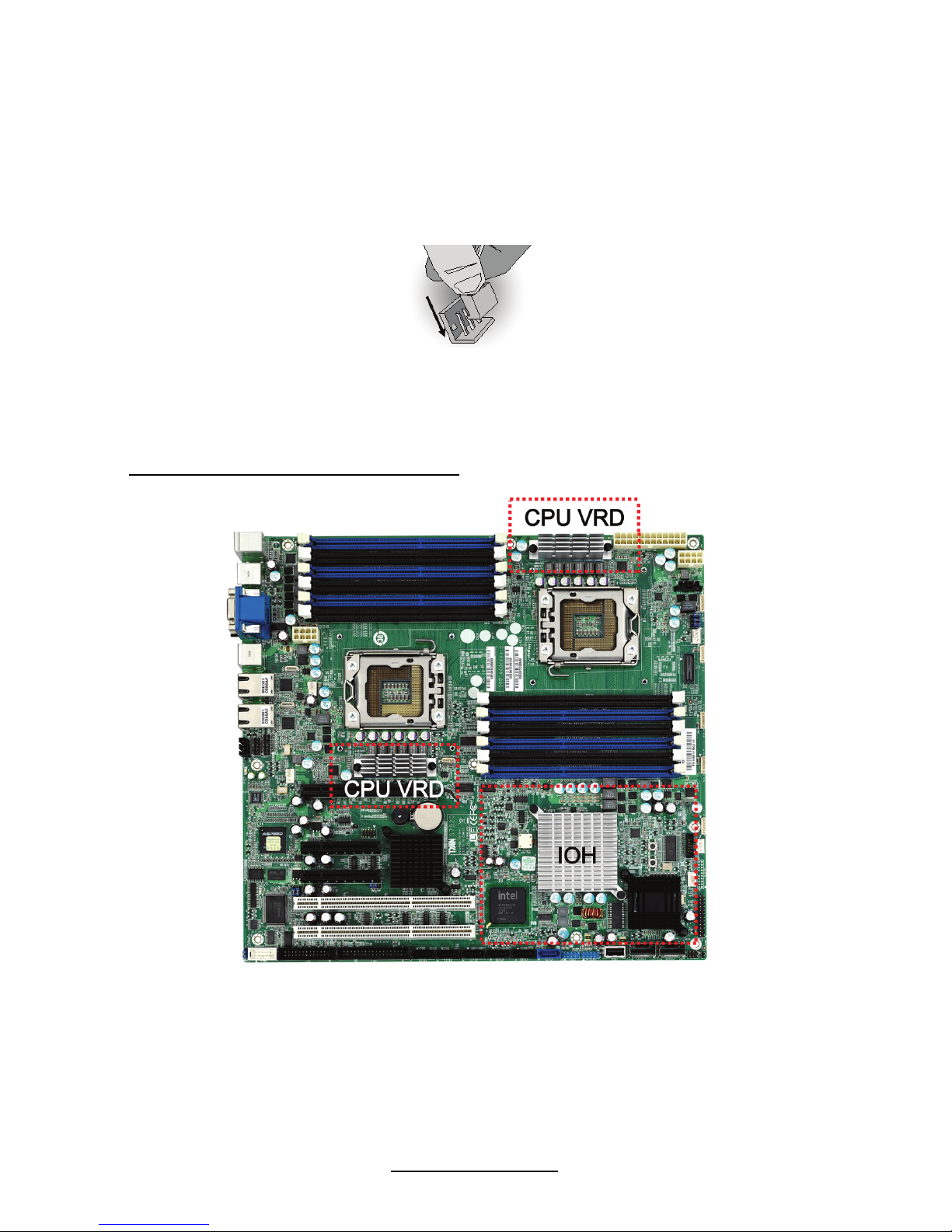
CPU VRD/IOH Heat Dispersion Notice
INSTALL FAN INTO CHASSIS TO LET AIR FLOW IN!!!
- To ensure that the board runs efficiently and does not overheat, make sure there
is air flow around the CPU VRD/IOH (as shown) to help disperse the heat
generated around the area.

28
http://www.tyan.com
2.7 Tips on Installing Motherboard in Chassis
Before installing your motherboard, make sure your chassis has the necessary
motherboard support studs installed. These studs are usually metal and are gold in
color. Usually, the chassis manufacturer will pre-install the support studs. If you are
unsure of stud placement, simply lay the motherboard inside the chassis and align
the screw holes of the motherboard to the studs inside the case. If there are any
studs missing, you will know right away since the motherboard will not be able to be
securely installed.
Some chassis’ include plastic studs instead of metal. Although the plastic studs are
usable, TYAN recommends using metal studs with screws that will fasten the
motherboard more securely in place.
Below is a chart detailing what the most common motherboard studs look like and
how they should be installed.
29
http://www.tyan.com
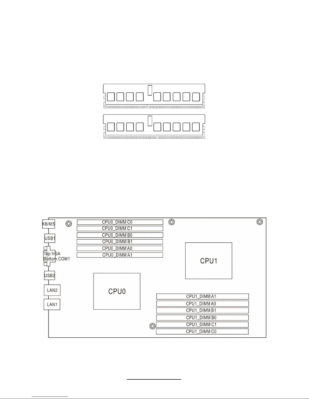
2.8 Installing the Memory
Before installing memory, ensure that the memory you have is compatible with
the motherboard and processor. Check the TYAN Web site at: www.tyan.com
for details of the type of memory recommended for your motherboard.
The following diagram shows common types of DDR3 memory modules.
Key points to note before installing memory:
Automatic memory bus frequency setting based on memory configuration
and memory SPD information (to be adjusted by BIOS)
Supports up to 96GB (8GB x 12 DIMMs)
Supports un-buffered ECC/Non-ECC modules
Supports ECC Registered DDR3-800/1066/1333 memory modules
Supports SR, DR, QR Rank Module
All memory must be of the same type and density
Always populate from DIMM0 first
 Loading...