

TYAN S7002 User Manual

S7002
Version 1.00
Copyright
Copyright © MiTAC Computer Corporation, 2009. All rights reserved. No part of
this manual may be reproduced or translated without prior written consent from
MiTAC Computer Corp.
Trademark
All registered and unregistered trademarks and company names contained in
this manual are property of their respective owners including, but not limited to
the following.
TYAN® is a trademark of MiTAC Computer Corporation
Intel
®
is a trademark of Intel® Corporation.
AMI
®
, AMIBIOS® and combinations thereof are trademarks of AMI Technologies.
Microsoft
®
, Windows® are trademarks of Microsoft Corporation.
IBM
®
, PC®, AT® and PS/2® are trademarks of IBM Corporation.
Winbond
®
is a trademark of Winbond Electronics Corporation.
Notice
Information contained in this document is furnished by MiTAC Computer
Corporation and has been reviewed for accuracy and reliability prior to printing.
MiTAC assumes no liability whatsoever, and disclaims any express or implied
warranty, relating to sale and/or use of TYAN
®
products including liability or
warranties relating to fitness for a particular purpose or merchantability. MiTAC
retains the right to make changes to product descriptions and/or specifications
at any time, without notice. In no event will MiTAC be held liable for any direct
or indirect, incidental or consequential damage, loss of use, loss of data or other
malady resulting from errors or inaccuracies of information contained in this
document.

http://www.TYAN.com
2

http://www.TYAN.com
3
Contents
S7002 ................................................................................................1
Before you begin… ...........................................................................5
Chapter 1: Instruction .......................................................................7
1.1 - Congratulations ..........................................................................................7
1.2 - Hardware Specifications.............................................................................7
1.3 - Software Specifications ............................................................................16
1.4 - AST2050 User Guide ...............................................................................16
Chapter 2: Board Installation .........................................................17
2.1 - Board Image.............................................................................................18
2.2 - Block Diagram ..........................................................................................19
2.3 - Board Parts, Jumpers and Connectors.....................................................20
2.4 - Installing the Processor ............................................................................30
2.5 - Heat sink Installation ................................................................................32
2.6 - Thermal Interface Material........................................................................33
2.7 - Finishing Installing the Heat sink ..............................................................34
2.8 - Tips on Installing Motherboard in Chassis................................................35
2.9 - Installing the Memory ...............................................................................37
2.10 - Attaching Drive Cables ...........................................................................40
2.11 - Installing Add-In Cards ...........................................................................41
2.12 - Installing I/O Shield.................................................................................42
2.13 - Connecting External Devices .................................................................43
2.14 - Installing the Power Supply ....................................................................44
2.15 - Finishing Up ...........................................................................................45
Chapter 3: BIOS Setup....................................................................47
3.1 - About the BIOS.........................................................................................47
3.2 - BIOS Menu Bar ........................................................................................47
3.3 - Setup Basics ............................................................................................48
3.4 - Getting Help .............................................................................................48
3.5 - In Case of Problems .................................................................................48
3.6 - BIOS Main Menu ......................................................................................48
3.7 - BIOS Advanced Menu ..............................................................................50
3.8 - PCI PnP Menu..........................................................................................73
3.9 - Boot Menu ................................................................................................75
3.10 - Security Menu.........................................................................................79
3.11 - Chipset Menu .........................................................................................80
3.12 - Exit Menu ...............................................................................................86
Chapter 4: Diagnostics ...................................................................87
4.1 - Beep Codes..............................................................................................87
4.2 - Flash Utility...............................................................................................87
4.3 - AMIBIOS Post Code.................................................................................88
Appendix: How to Make a Driver Diskette.....................................91
Glossary...........................................................................................93
Technical Support...........................................................................99

http://www.TYAN.com
4

http://www.TYAN.com
5
Before you begin…
Check the box contents!
The retail motherboard package should contain the following:
1x S7002 Motherboard
6 x SATA Cable
1 x S7002 User’s manual
1 x S7002 Quick reference guide
1 x TYAN® Driver CD
1 x I/O shield

http://www.TYAN.com
6
http://www.TYAN.com
7
Chapter 1: Instruction
1.1 - Congratulations
You have purchased one of the most powerful server solutions based on the
Intel® Tylersburg chipset. The TYAN® S7002 series motherboard is designed to
support up to two Intel
®
Nehalem-EP 2S processors and up to 64GB DDR3800/1066/1333 memory. Leveraging the advanced technology from Intel, the
TYAN® S7002 series is capable of offering a scalable 32 and 64-bit computing
environment with high-bandwidth memory design and lightning-fast PCI-E bus
providing a rich feature set and incredible performance.
The TYAN S7002 series is designed around several different configurations
which are detailed in the following 1.2 Hardware Specification section:
1.2 - Hardware Specifications
TYAN S7002-LE (S7002G2NR-LE)
Supported CPU Series
Intel Xeon 5500 series QC/DC
processors
Socket Type / QTY LGA1366 / (2)
Thermal Design Power (TDP)
wattage
130W
Processor
System Bus (MHz) 1333/1066/800
IOH / ICH Intel 5500 / ICH10R
Chipset
Super I/O Winbond W83627
Supported DIMM Qty (8) DIMM sockets
DIMM Type / Speed DDR3 800/1066/1333 RDIMM, UDIMM
Capacity Up to 64GB
Memory channel 6 channels (3-channel per CPU)
Memory
Memory voltage 1.5V
PCI-E
(1) PCI-E x16 slot (Gen 2) / (2) PCI-E
x8 slots (w/ x4 link)
Expansion Slots
Recommended TYAN Riser
Card
M2083-RS, PCI-E x16 1U riser card
(left)
Port QTY (2)
LAN
Controller Intel 82574
Connector (6)
Controller ICH10R
Speed 3.0 Gb/s
Storage SATA
RAID S/W RAID 0,1,5,10 standard
http://www.TYAN.com
8
Connector type D-Sub 15pin(Embedded VGA)
Resolution 1600x1200@60Hz
Graphic
Chipset Aspeed AST2050
USB (8) USB2.0 ports (4 at rear, 4 via cable)
COM (2) ports (1 at rear, 1 via cable)
SAS (8) SAS connectors
VGA (1) D-Sub 15pin VGA port
RJ-45 (2) GbE ports
Power
SSI 24-pin + 8-pin + 8-pin power connectors / EPS12V
Front Panel (1) 2x12 pin SSI Front Panel header
Input /Output
SATA (6) SATAII connectors
Chipset Winbond W83793G
Voltage
Monitors voltage for CPU, memory, chipset & power
supply
Fan Total (5) 4-pin headers
Temperature Monitors temperature for CPU & system environment
LED
Fan fail LED indicator / Over temperature warning
indicator
System
Monitoring
Others Chassis intrusion detection / Watch Dog timer support
Brand / ROM
size
16MB / AMI
BIOS
Feature
Plug and Play (PnP) /PCI2.3 /WfM2.0 /SMBIOS2.3
/PXE Boot / ACPI 2.0 power management /Power on
mode after power recovery / Auto-configurable of hard
disk types / Multiple boot options
Form Factor SSI CEB
Form Factor
Board
Dimension
12"x10.5" (305x267mm)
Operation System
OS supported
list
Please refer to our OS supported list.
FCC (Doc) Class B
Regulation
CE (Doc) Yes
Operating
Temp
10° C ~ 35° C (50° F~ 95° F)
Non-operating
Temp
- 40° C ~ 70° C (-40° F ~ 158° F)
Operating
Environment
In/Nonoperating
Humidity
90%, non-condensing at 35° C
RoHS
RoHS 6/6
Complaint
Yes
Motherboard (1) TYAN motherboard
Manual (1) User's manual / (1) Quick Ref. Guide
Accessory list
Installation CD (1) TYAN Installation CD

http://www.TYAN.com
9
I/O Shield (1) I/O Shield
Cable (6) SATA signal cables
Riser Card M2083-RS, PCI-E 1U riser card (left)
Optional
accessories for
future upgrade
Cable
(1) CCBL-0615, COM port cable / (1) CCBL-0311,
SATA 1-to-2 power cable / (1) CCBL-035J, USB
bracket cable
TYAN S7002 (S7002WGM2NR/S7002WGP2NR-LE)
Supported CPU Series
Intel Xeon 5500 series QC/DC processors
Socket Type / QTY LGA1366 / (2)
Thermal Design Power (TDP)
wattage
130W
Processor
System Bus (MHz) Intel QuickPath Interconnect (QPI)
IOH / ICH Intel 5520 / ICH10R
Chipset
Super I/O Winbond W83627
Supported DIMM Qty (8) DIMM sockets
DIMM Type / Speed DDR3 800/1066/1333 RDIMM, UDIMM
Capacity Up to 64GB
Memory channel 6 channels (3-channel per CPU)
Memory
Memory voltage 1.5V
PCI-E
(1) PCI-E x8 slot (w/ x4 link) / (1) PCI-E
x16 slot (Gen 2) / (2) PCI-E x8 slots (Gen
2)
Expansion
Slots
Recommended TYAN Riser
Card
M2083-RS, PCI-E x16 1U riser card (left)
Port QTY (2)
LAN
Controller Intel 82574
Connector (8)
Controller LSI SAS1068E
Speed 3.0 Gb/s
SAS
RAID S/W RAID 0,1,1E standard
Connector (6)
Controller ICH10R
Speed 3.0 Gb/s
Storage
SATA
RAID S/W RAID 0,1,5,10 standard

http://www.TYAN.com
10
Connector
type
D-Sub 15pin(Embedded VGA)
Resolution 1600x1200@60Hz
Graphic
Chipset Aspeed AST2050
USB (8) USB2.0 ports (4 at rear, 4 via cable)
COM (2) ports (1 at rear, 1 via cable)
PS/2 (1) PS/2 connector
SAS (8) SAS connectors
VGA (1) D-Sub 15pin VGA port
RJ-45 (2) GbE ports
Power SSI 24-pin + 8-pin + 8-pin power connectors / EPS 12V
Front Panel (1) 2x12 pin SSI Front Panel header
Input /Output
SATA (6) SATAII connectors
Chipset Winbond W83793G
Voltage Monitors voltage for CPU, memory, chipset & power supply
Fan Total (5) 4-pin headers
Temperature Monitors temperature for CPU & system environment
LED Fan fail LED indicator / Over temperature warning indicator
System
Monitoring
Others Chassis intrusion detection / Watch Dog timer support
Onboard
Chipset
Onboard Aspeed AST2050
AST2050 IPMI
Feature
IPMI 2.0 compliant baseboard management controller
(BMC) / Supports storage over IP and remote platform-
flash/ BIOS update / USB 2.0 virtual Hub(S7002WGM2NR)
Server
Management
AST2050
iKVM Feature
24bit High quality video compression / Dual 10/100 Mb/s
MAC interfaces, support KVM function(S7002WGP2NR-LE)
Brand / ROM
size
16MB / AMI
BIOS
Feature
Plug and Play (PnP) /PCI2.3 /WfM2.0 /SMBIOS2.3 /PXE
Boot / ACPI 2.0 power management /Power on mode after
power recovery / User-configurable H/W monitoring / Auto-
configurable of hard disk types / Multiple boot options
http://www.TYAN.com
11
Form Factor SSI CEB
Form Factor
Board
Dimension
12"x10.5" (305x267mm)
Operation System
OS supported
list
Please refer to our OS supported list.
FCC (Doc) Class B
Regulation
CE (Doc) Yes
Operating Temp 10° C ~ 35° C (50° F~ 95° F)
Non-operating
Temp
- 40° C ~ 70° C (-40° F ~ 158° F)
Operating
Environment
In/Non-
operating
Humidity
90%, non-condensing at 35° C
RoHS
RoHS 6/6
Complaint
Yes
Motherboard (1) TYAN motherboard
Manual (1) User's manual / (1) Quick Ref. Guide
Installation CD (1) TYAN Installation CD
I/O Shield (1) I/O Shield
Accessory list
Cable (6) SATA signal cables
Riser Card M2083-RS, PCI-E 1U riser card (left)
Optional
accessories for
future upgrade
Cable
(1) CCBL-0615, COM port cable / (1) SAS cable
for S7002 / (1) CCBL-0311, SATA 1-to-2 power
cable / (1) CCBL-035J, USB bracket cable
TYAN S7002-LE (S7002WGM2NR-LE)
Supported CPU Series Intel Xeon 5500 series QC/DC processors
Socket Type / QTY LGA1366 / (2)
Thermal Design Power (TDP)
wattage
130W
Processor
System Bus (MHz) 1333/1066/800
IOH / ICH Intel 5500 / ICH10R
Chipset
Super I/O Winbond W83627
Memory
Supported DIMM Qty (8) DIMM sockets
http://www.TYAN.com
12
DIMM Type / Speed DDR3 800/1066/1333 RDIMM, UDIMM
Capacity Up to 64GB
Memory channel 6 channels (3-channel per CPU)
Memory
Memory voltage 1.5V
PCI-E
(1) PCI-E x16 slot (Gen 2) / (2) PCI-E x8 slots (w/
x4 link)
Expansion
Slots
Recommended TYAN
Riser Card
M2083-RS, PCI-E x16 1U riser card (left)
Port QTY (2)
LAN
Controller Intel 82574
Connector (8)
Controller LSI SAS1068E
Speed 3.0 Gb/s
SAS
RAID S/W RAID 0,1,1E standard
Connector (6)
Controller ICH10R
Speed 3.0 Gb/s
Storage
SATA
RAID S/W RAID 0,1,5,10 standard
Connector type D-Sub 15pin (Embedded VGA)
Resolution 1600x1200@60Hz
Graphic
Chipset Aspeed AST2050
USB (8) USB2.0 ports (4 at rear, 4 via cable)
COM (2) ports (1 at rear, 1 via cable)
SAS (8) SAS connectors
VGA (1) D-Sub 15pin VGA port(Embedded VGA)
RJ-45 (2) GbE ports
Power
SSI 24-pin + 8-pin + 8-pin power connectors /
EPS-12V
Front Panel (1) 2x12 pin SSI Front Panel header
Input /Output
SATA (6) SATAII connectors
Chipset Winbond W83793G
Voltage
Monitors voltage for CPU, memory, chipset &
power supply
System
Monitoring
Fan Total (5) 4-pin headers
http://www.TYAN.com
13
Temperature
Monitors temperature for CPU & system
environment
LED
Fan fail LED indicator / Over temperature
warning indicator
System
Monitoring
Others
Chassis intrusion detection / Watch Dog timer
support
Onboard Chipset Onboard Aspeed AST2050
AST2050 IPMI Feature
IPMI 2.0 compliant baseboard management
controller (BMC) / Supports storage over IP and
remote platform-flash/ BIOS update / USB 2.0
virtual Hub
Server
Management
AST2050 iKVM Feature
24bit High quality video compression / Dual
10/100 Mb/s MAC interfaces
Brand / ROM size 16MB / AMI
BIOS
Feature
Plug and Play (PnP) /PCI2.3 /WfM2.0
/SMBIOS2.3 /PXE Boot / ACPI 2.0 power
management /Power on mode after power
recovery / Auto-configurable of hard disk types /
Multiple boot options
Form Factor SSI CEB
Form Factor
Board Dimension 12"x10.5" (305x267mm)
Operation
System
OS supported list Please refer to our OS supported list.
FCC (Doc) Class B
Regulation
CE (Doc) Yes
Operating Temp 10° C ~ 35° C (50° F~ 95° F)
Non-operating Temp - 40° C ~ 70° C (-40° F ~ 158° F)
Operating
Environment
In/Non-operating
Humidity
90%, non-condensing at 35° C
RoHS
RoHS 6/6 Complaint Yes
Motherboard (1) TYAN motherboard
Manual (1) User's manual / (1) Quick Ref. Guide
Installation CD (1) TYAN Installation CD
I/O Shield (1) I/O Shield
Accessory list
Cable (6) SATA signal cables
http://www.TYAN.com
14
Riser
Card
M2083-RS, PCI-E 1U riser card (left)
Optional accessories
for future upgrade
Cable
(1) CCBL-0615, COM port cable / (1) SAS cable for
S7002 / (1) CCBL-0311, SATA 1-to-2 power cable / (1)
CCBL-035J, USB bracket cable
TYAN S7002-LE (S7002GM2NR-LE)
Supported CPU Series
Intel Xeon 5500 series
QC/DC processors
Socket Type / QTY LGA1366 / (2)
Thermal Design Power (TDP) wattage
130W
Processor
System Bus (MHz) 1333/1066/800
IOH / ICH Intel 5500 / ICH10R
Chipset
Super I/O Winbond W83627
Supported DIMM Qty (8) DIMM sockets
DIMM Type / Speed
DDR3 800/1066/1333
RDIMM, UDIMM
Capacity Up to 64GB
Memory channel
6 channels (3-channel per
CPU)
Memory
Memory voltage 1.5V
PCI-E
(1) PCI-E x16 slot (Gen 2) /
(2) PCI-E x8 slots (w/ x4
link)
Expansion Slots
Recommended TYAN Riser Card
M2083-RS, PCI-E x16 1U
riser card (left)
Recommended
Barebone /
Chassis
1U Barebone GT20-B7002
Port QTY (2)
LAN
Controller Intel 82574
Connector (6)
Controller ICH10R
Speed 3.0 Gb/s
Storage SATA
RAID S/W RAID 0,1,5,10
http://www.TYAN.com
15
standard
Connector
type
D-Sub 15pin
Resolution 1600x1200@60Hz
Graphic
Chipset Aspeed AST2050
USB (8) USB2.0 ports (4 at rear, 4 via cable)
COM (2) ports (1 at rear, 1 via cable)
VGA (1) D-Sub 15pin VGA port
RJ-45 (2) GbE ports
Power SSI 24-pin + 8-pin + 8-pin power connectors / EPS 12V
Front Panel (1) 2x12 pin SSI Front Panel header
Input /Output
SATA (6) SATAII connectors
Chipset Winbond W83793G
Voltage
Monitors voltage for CPU, memory, chipset & power
supply
Fan Total (5) 4-pin headers
Temperature Monitors temperature for CPU & system environment
LED
Fan fail LED indicator / Over temperature warning
indicator
System
Monitoring
Others Chassis intrusion detection / Watch Dog timer support
Onboard
Chipset
Onboard Aspeed AST2050
AST2050 IPMI
Feature
IPMI 2.0 compliant baseboard management controller
(BMC) / Supports storage over IP and remote platform-
flash/ BIOS update / USB 2.0 virtual Hub
Server
Management
Server
Management
AST2050
iKVM Feature
24bit High quality video compression / Dual 10/100 Mb/s
MAC interfaces
Brand / ROM
size
16MB / AMI
BIOS
Feature
Plug and Play (PnP) /PCI2.3 /WfM2.0 /SMBIOS2.3 /PXE
Boot / ACPI 2.0 power management /Power on mode
after power recovery / Auto-configurable of hard disk
types / Multiple boot options
Form Factor SSI CEB
Form Factor
Board
Dimension
12"x10.5" (305x267mm)
http://www.TYAN.com
16
Operation System
OS supported list Please refer to our OS supported list.
FCC (Doc) Class B
Regulation
CE (Doc) Yes
Operating Temp 10° C ~ 35° C (50° F~ 95° F)
Non-operating
Temp
- 40° C ~ 70° C (-40° F ~ 158° F)
Operating
Environment
In/Non-operating
Humidity
90%, non-condensing at 35° C
RoHS
RoHS 6/6
Complaint
Yes
Motherboard (1) TYAN motherboard
Manual (1) User's manual / (1) Quick Ref. Guide
Installation CD (1) TYAN Installation CD
I/O Shield (1) I/O Shield
Accessory list
Cable (6) SATA signal cables
Riser Card M2083-RS, PCI-E 1U riser card (left)
Optional accessories
for future upgrade
Cable
(1) CCBL-0615, COM port cable / (1) CCBL-
0311, SATA 1-to-2 power cable / (1) CCBL-
035J, USB bracket cable
Note:
Instructions and images within this manual are represented
S7002WAP2NR. For different SKUs some variations in
detail are possible.
Remember to visit TYAN
®
’s Website at http://www.TYAN.com. There you
can find information on all of TYAN
®
’s products with FAQs, online manuals
and BIOS upgrades and more.
1.3 - Software Specifications
For OS (operation system) support, please check the TYAN® website for the
latest information.
1.4 - AST2050 User Guide
Remember to visit TYAN®’s Website at http://www.TYAN.com for AST2050
updated user guide.
http://www.TYAN.com
17
Chapter 2: Board Installation
You are now ready to install your motherboard.
How to install our products right… the first time
The first thing you should do is reading this user’s manual. It contains important
information that will make configuration and setup much easier. Here are some
precautions you should take when installing your motherboard:
(1) Ground yourself properly before removing your motherboard from the
antistatic bag. Unplug the power from your computer power supply and
then touch a safely grounded object to release static charge (i.e. power
supply case). For the safest conditions, TYAN
®
recommends wearing a
static safety wrist strap.
(2) Hold the motherboard by its edges and do not touch the bottom of the
board, or flex the board in any way.
(3) Avoid touching the motherboard components, IC chips, connectors,
memory modules, and leads.
(4) Place the motherboard on a grounded antistatic surface or on the
antistatic bag that the board was shipped in.
(5) Inspect the board for damage.
The following pages include details on how to install your motherboard into your
chassis, as well as installing the processor, memory, disk drives and cables.
Note:
DO NOT APPLY POWER TO THE BOARD IF IT HAS
BEEN DAMAGED.
http://www.TYAN.com
18
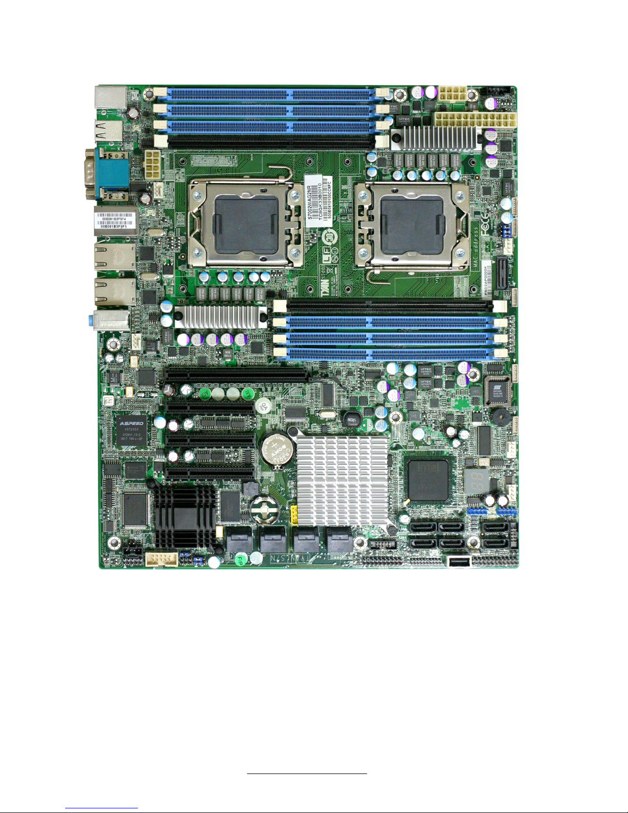
2.1 - Board Image
This diagram is representative of the latest motherboard (S7002WAP2NR)
revision available at the time of publishing. The board you receive may
not look exactly like the above diagram.
http://www.TYAN.com
19
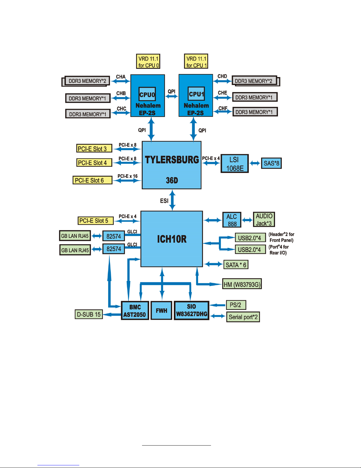
2.2 - Block Diagram
S7002 Block Diagram (Represents all SKUs)
http://www.TYAN.com
20
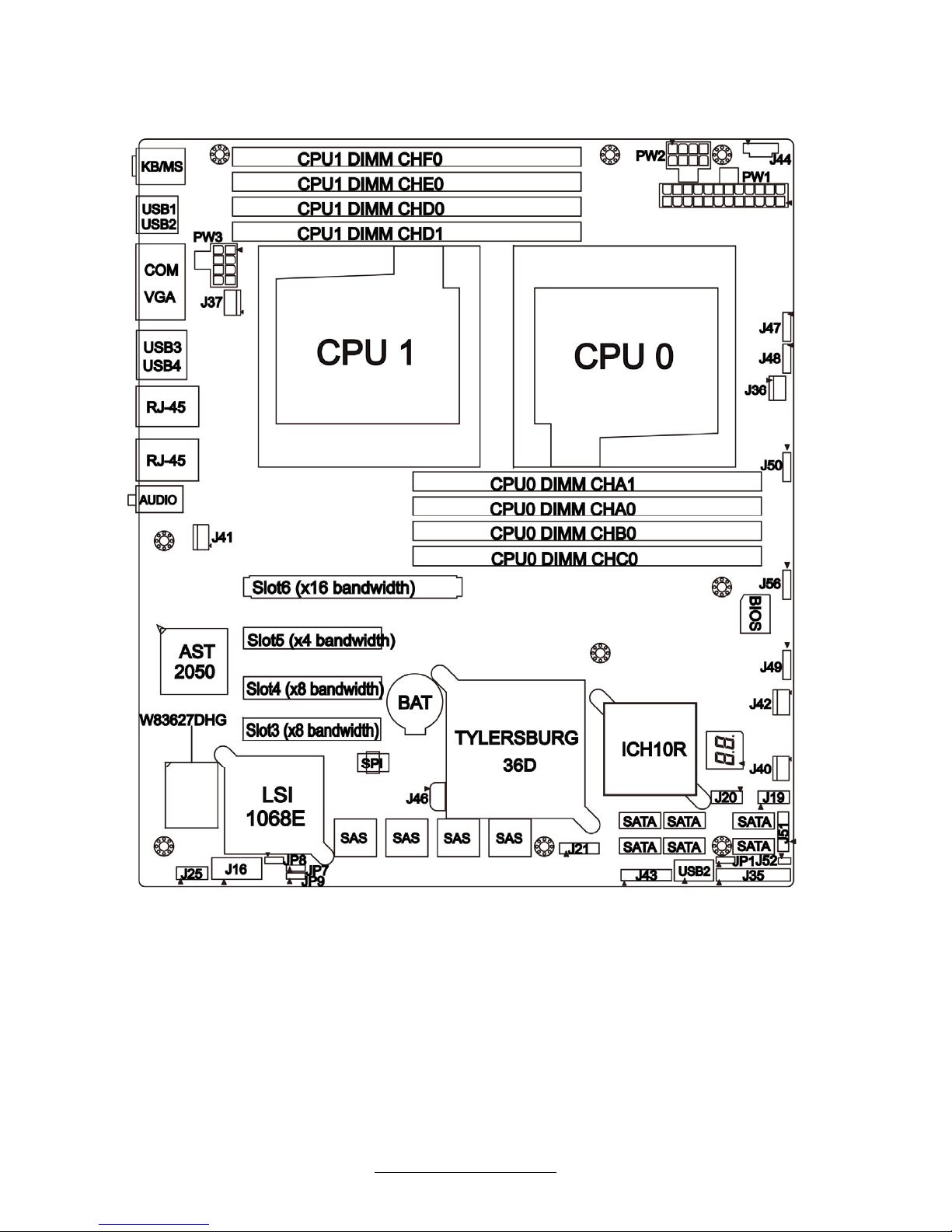
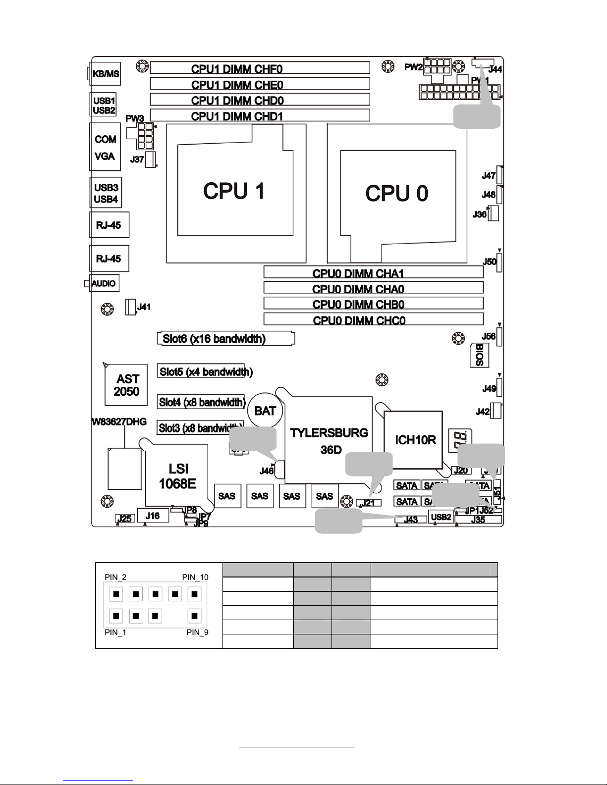
2.3 - Board Parts, Jumpers and Connectors
This diagram is representative of the latest board revision (S7002WAP2NR)
available at the time of publishing. The board you receive may not look exactly
like the above diagram.
http://www.TYAN.com
21
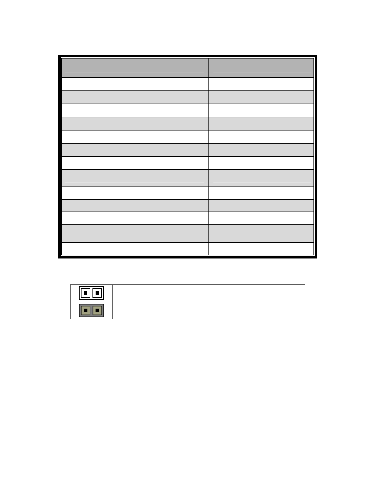
Jumpers & Connectors
Jumper/Connector Function
J36/J37/J40/J41/J42/J47/J48/J49/J50/J56 Fan connectors
J16 COM2 Header
J19/J20 Front USB Header
J25 Front Panel Audio
J35 Front Panel Header
J43 Clear CMOS
J44 PSMI Connector
J46 IPMB Pin Header
J21/J51 SAS SGPIO Header
J52 BMC RST Button
JP1 Clear CMOS
JP7
On Board SAS
LSI1068E EN/DIS
JP8/JP9 COM2 Select
Jumper Legend
OPEN - Jumper OFF
Without jumper cover
CLOSED - Jumper ON
With jumper cover
http://www.TYAN.com
22
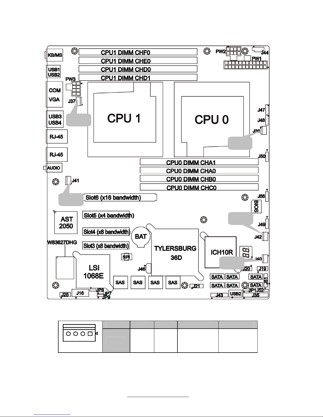
Jumper Placement
J36/J37/J40/J41/J42: 4-Pin FAN Connector
Pin 1 2 3 4
Pin_1
Signal
GND +12V FAN_TACH FAN_PWM
J36
J40
J42
J41
J37
http://www.TYAN.com
23
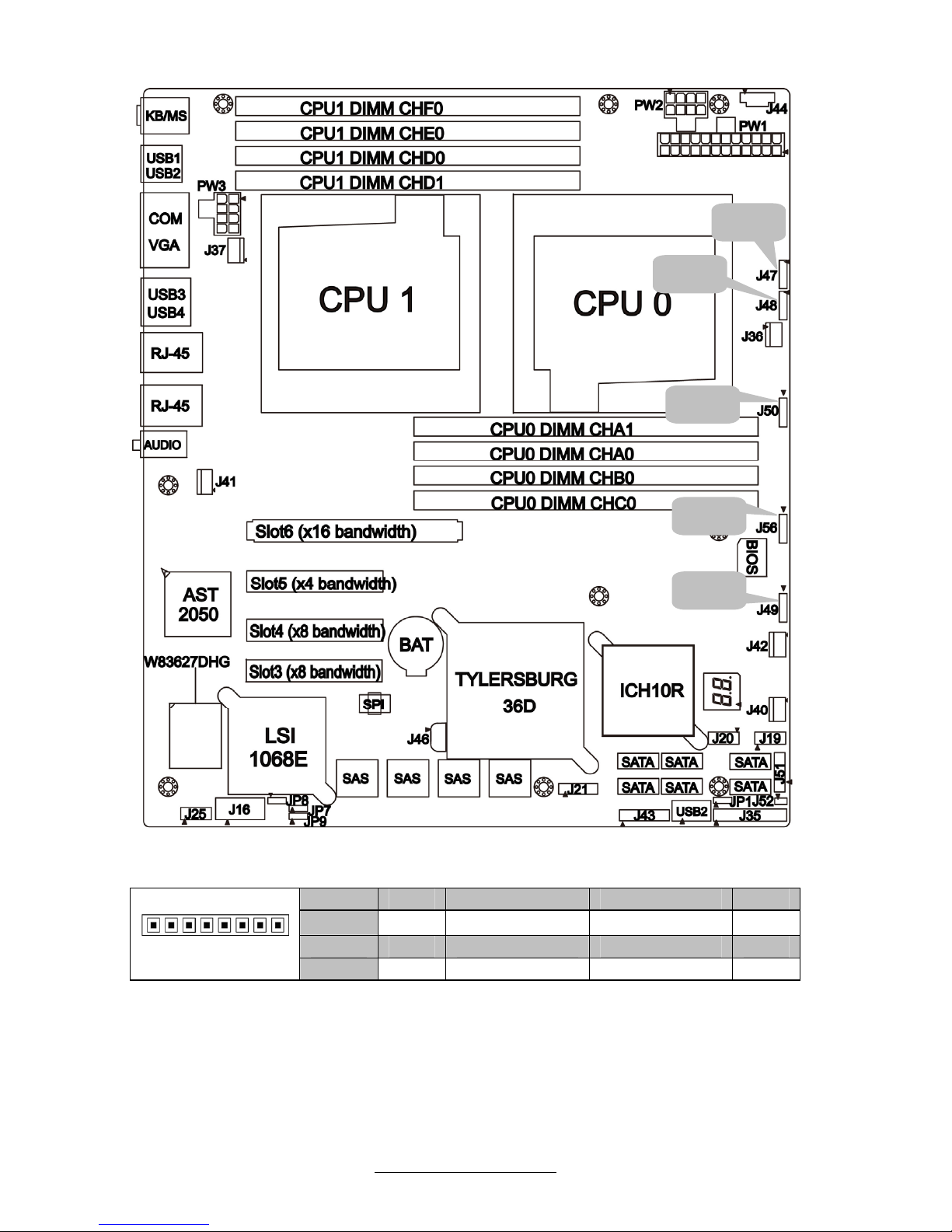
J47/J48/J49/J50/J56: 8-Pin FAN Connector
Pin 1 2 3 4
Signal
PWM VDD_12_RUN TACHIN GND
Pin 5 6 7 8
Pin_1
Signal
GND TACHIN VDD_12_RUN PWM
J50
J47
J49
J56
J48
http://www.TYAN.com
24
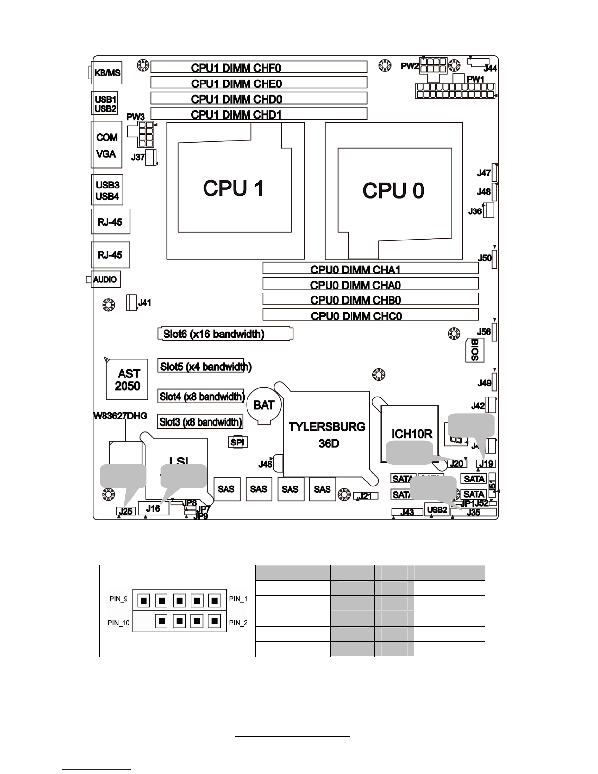
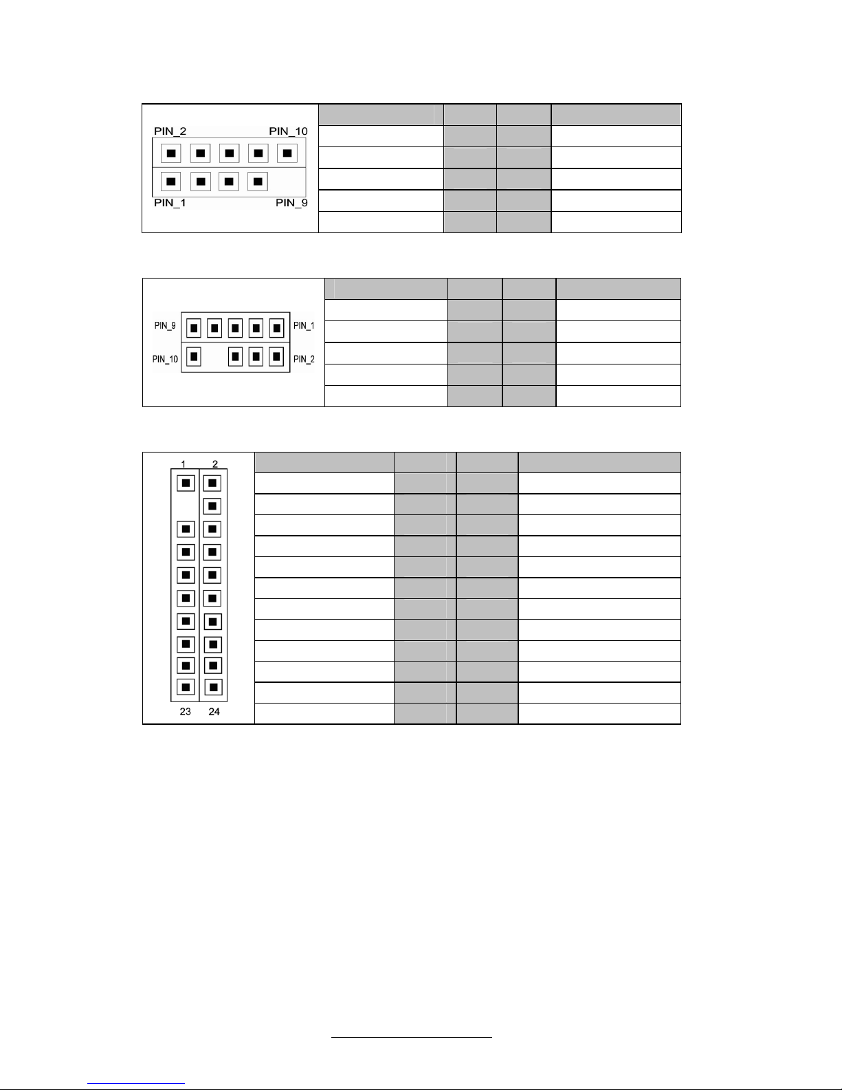
J16: Com2 Header
Signal Pin Pin Signal
DCD
1 2
DSR
RXD
3 4
RTS
TXD
5 6
CTS
DTR
7 8
RI
GND
9 10
Key
J20
J16
J19
J25
J35
http://www.TYAN.com
25
J19/J20: Front USB Header
Signal Pin Pin Signal
+5V
1 2
+5V
USB DATA1-
3 4
USB DATA2-
USBDATA1+
5 6
USBDATA2+
GND
7 8
GND
Key
9 10
GND
J25: Front Panel Audio
Signal Pin Pin Signal
MIC2-L
1 2
GND
MIC2-R
3 4
FP_Present
LINE2-R
5 6
MIC2-JD
FP IO Sense
7 8
Key
LINE2-R
9 10
LINE2-JD
J35: Front Panel Header
Signal Pin Pin Signal
PW_LED+
1 2
FP_PWER(3.3V)
KEY
3 4
ID_ LED+
PW_LED-
5 6
ID_ LED-
HD_ LED+
7 8
FAULT_ LED-
HD_ LED-
9 10
FAULT_ LED-
PW_SW#
11 12
LAN1_ACTLE+
GND
13 14
LAN1_ACTLE-
RST_SW#
15 16
SDA
GND
17 18
SCL
SYS_ID_SW#
19 20
INTRUDER#
GND
21 22
LAN2_ACTLED+
NMI_SW#
23 24
LAN2_ACTLED-
http://www.TYAN.com
26
J21/J51 SAS SGPIO Header
Signal Pin Pin Signal
SCL
1 2
SDATA IN
SDA
3 4
SDATA OUT-
GND
5 6
SLOAD
KEY
7 8
SCLOCK
NC
9 10
HD_ERROR_LED
J44
J43
J46
J21
J52
J51
http://www.TYAN.com
27
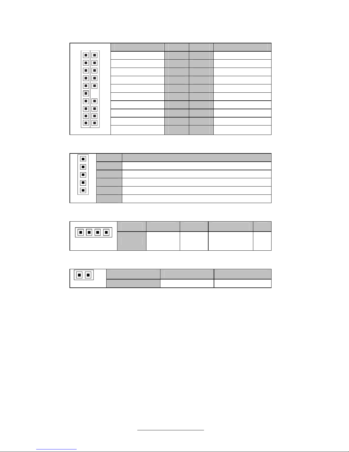
J43: Fan Connector for Barebones Systems
Signal Pin Pin Signal
TACH1
1 2
TACH6
TACH2
3 4
TACH7
TACH3
5 6
TACH8
TACH4
7 8
TACH9
TACH5
9 10
TACH10
GND
11 12
KEY PIN
PWM2
13 14
PWM1
TACH11
15 16
TACH13
TACH12
17 18
TACH14
Pin_1 2
19 20
NC
19 20
PWM3
J44: PSMI Connector
Pin Signal
1
SMB_CLK
2
SMB_DAT
3
PSU_SMBALERT_N
4
GND
Pin_1
5
V3.3
J46: IPMB Connector
Pin 1 2 3 4
Pin_1
Signal
IPMB
DATA
GND IPMB CLK NC
J52 BMC RST Button
Pin 1 2
Pin_1
Signal
RST# GND
http://www.TYAN.com
28
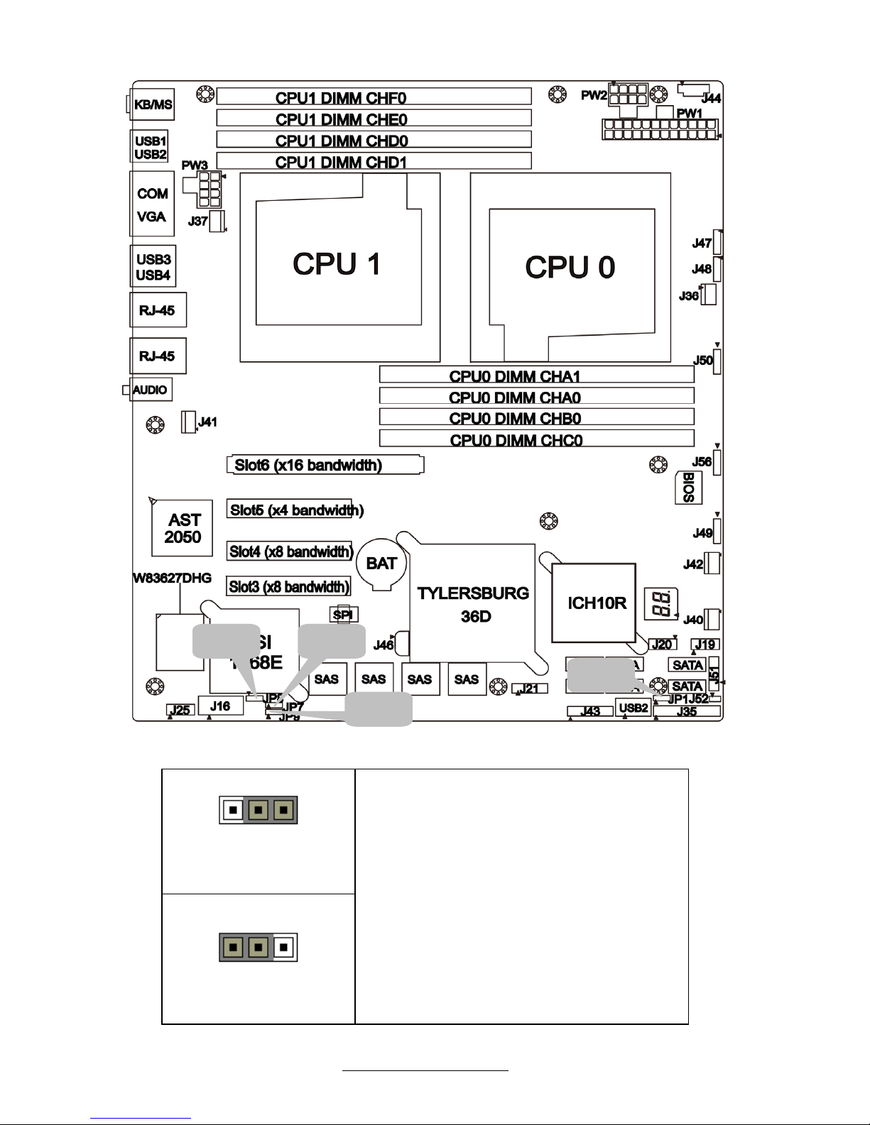
JP1: Clear CMOS
Pin_3 Pin_1
Normal
(Default)
Pin_3 Pin_1
Clear CMOS
You can reset the CMOS settings by
using this jumper if you have forgotten
your system/setup password or need to
clear system BIOS setting.
- Power off system and disconnect
both power connectors from the
motherboard
- Put jumper cap back to Pin_1 and
Pin_2 (default setting)
- Use jumper cap to close Pin_2 and
Pin_3 for several seconds to Clear
CMOS
Reconnect power & power on system
JP1
JP7JP8
JP9

http://www.TYAN.com
29
JP7 On Board SAS LSI1068E Enabled/Disabled
Pin_3 Pin_1
Pin 1 2 3
Pin_3 Pin_1
Signal
PLTRST# SAS_RST# GND
Note: Pin1-2: Enable onboard SAS chip;
Pin2-3: Disable onboard SAS chip
JP8/JP9: COM2 Select
Pin_3 Pin_1
Pin 1 2 3
Pin_3 Pin_1
Signal
SIO RX COM2_RX
BMC
RX
Note: Pin1-2: <Default>SIO to COM2;
Pin2-3: BMC UART2 to COM2
Onboard ID LED
You can identify the specific system using this LED. Users from
remote site could also activate ID LED by input a few commands in
IPMI, detailed software support please visit http://www.tyan.com
for
lastest AST2050 user guide.
Pin Signal
+ P3V3_AUX
- ID_SW_L
State Color Description
On Blue System identified
+ -
Off Off System not identified
http://www.TYAN.com
30
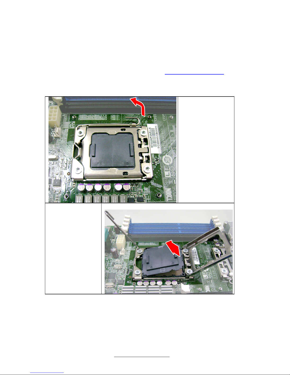
2.4 - Installing the Processor
Your brand new S7002 supports the latest Tylersburg platform from Intel
®
.
Only Intel
®
“Nehalem-EP 2S” processors are certified and supported with
this motherboard.
Check our website for latest processor support. http://www.TYAN.com
TYAN
®
is not liable for damage as a result of operating an unsupp-
-orted configuration.
Step1:
Press the lever
and unlock the
CPU socket.
Step2:
Lift the CPU
protection cap
up and lay the
CPU into the
socket(A),
ensuring pin1
is correctly
located(B).
A
 Loading...