

Page 1

http://www.TYAN.com
1
Triumph i845GV
///
S6601
Version 1.0
Copyright
Copyright © TYAN Computer Corporation, 2005. All rights reserved. No part of
this manual may be reproduced or translated without prior written consent from
TYAN Computer Corp.
Trademark
All registered and unregistered trademarks and company names contained in
this manual are property of their respective owners including, but not limited to
the following.
TYAN, Triumph i845GV are trademarks of TYAN Computer Corpor ation.
Intel, Xeon, and combinations thereof are trademarks of Intel Corporation.
AMD, Athlon, and combinations thereof are trademarks of AMD Corporation.
Phoenix, Phoenix-AwardBIOS are trademarks of Phoenix Technologies.
Microsoft, Windows are trademarks of Microsoft Corporation.
SuSE,is a trademark of SuSE AG.
IBM, PC, AT, and PS/2 are trademarks of IBM Corporation.
Broadcom
®
is a trademark of Broadcom Corporation and/or its subsidiaries
ATI and Rage XL are trademarks of ATI Corporation
nVIDIA, nForce are trademarks of NVIDIA Corporation.
Notice
Information contained in this document is furnished by TYAN Computer
Corporation and has been reviewed for accuracy and reliability prior to printing.
TYAN assumes no liability whatsoever, and disclaims any express or implied
warranty, relating to sale and/or use of TYAN products including liability or
warranties relating to fitness for a particular purpose or merchantability. TYAN
retains the right to make changes to product descriptions and/or specifications
at any time, without notice. In no event will TYAN be held liable for any direct or
indirect, incidental or consequential damage, loss of use, loss of data or other
malady resulting from errors or inaccuracies of information contained in this
document
Page 2

http://www.TYAN.com
2
Table of Contents
Chapter 1 Introduction…………………………………………………………….… 3
1.1 Features & Specifications …………………………………………………..3
1.2 Layout…………………………………………………………… ………….5
1.3 Jumpers & Connectors Description …………………………………….....6
Chapter 2 Hardware Setup ……………………………………………………….…7
2.1
CPU Socket ………………………………………………………………….7
2.2 System Memory…………………………………………………………..…8
2.3 Power Connectors ………………………………………………………..…9
2.4 FAN Connectors ……………………………………………………………10
2.5 CMOS Memory Clearing Header………………………………………...11
2.6 Front Panel Switches & Indicators Connection Headers ………….…….12
2.7 External Keyboard/Mouse Connection Header …………………………13
2.8 System Management Bus Connection Header…………………….…..14
2.9 IDE Disk Drive Connector …………………………………………… ……15
2.10 PCI Expansion Slot………………………………………………………...16
2.11 Additional COM Port Connection Header ……………………… ………..17
2.12 Additional USB Port Connection Header ……………………………….....18
2.13 VGA Output Connection Header…………………………………………19
2.14 Compact Flash Memory Card Reader Socket……………………………20
2.15 Status Indicators……………………………………………………………..21
2.16 Power-On Switch …………………………………………………………..22
2.17 System-fail LED Connection Header……………………….……………23
2.18 Parallel Port Header……………………………………………………….24
2.19 External I/O Panel Connectors…………… …………………….………..25
Chapter 3 BIOS Setup …………………………………………………………..…27
3.1 Standard CMOS Features…………………………………… ……….…...28
3.2 Advanced BIOS Features……………………… …………………………31
3.3 Advanced Chipset Features………………………………………………34
3.4 Integrated Peripherals………………………………………… ……..……36
3.5 Power Management Setup………………………………………..………40
3.6 PnP/PCI Configurations……………………………………………..…….42
3.7 PC Health Menu…………………………………………………………….44
3.8 Load Fail-Safe Defaults……………………………………………..…….46
3.9 Load Optimized Defaults……………………………………………..…...46
3.10 Set Password…………………………………………………………..……46
3.11 Save & Exit Setup……………………………………………………….…46
3.12 Exit Without Saving………………………………………………………..46
Glossary………..…………………………………….……………………..………47
Technial Support………..………………………………….………………………53
Page 3

http://www.TYAN.com
3
Chapter 1: Introduction
1.1 Features & Specifications
CPU
• Supports Intel Pentium 4 socket 478 processor up to 3.06GHz and
later (based on 400/533MHz FSB)
Chipset
• Intel RG82845GV (845GV) / FW82801DB (ICH4)
Networking Security
• Onboard Cavium CN-1005 Security Macro Processor support
IPsec/SSL acceleration
Memory
• Two 184-pin DIMM sockets supporting 64-bit wide Single Channel
DDR 200/266/333 memory
• Up to 2GB, un-buffered and non-ECC memory capacity
LAN
• S6601E4H: 4x Intel 82551ER single port 10/100 Ethernet
• S6601V2E4H: 2x Intel 82541PI single port GbE Ethernet
4x Intel 82551ER single port 10/100 Ethernet
• S6601E6H: 6x Intel 82551ER single port 10/100 Ethernet
VGA
• Integrated graphics controller by Intel RG82845GV
PCI Expansion Slot
• 1x PCI 32bit/33MHz expansion slot (3.3V)
Internal I/O Headers
• 1x 44-pin Ultra DMA 100/66/33 connector
• 1x 50-pin IDE Interface Compact Flash Type II Socket
• 1x VGA header
• 1x LPT header
• 1x PS/2 Keyboard/Mouse header
• 1x COM header (COM1)
• 1x USB 2.0 header (Supports two USB 2.0 connectors)
• 1x SM Bus header (For SM Bus and I
2
C)
Page 4

http://www.TYAN.com
4
External I/O Connectors
• 1x COM port (COM2)
• 2x USB 2.0 connectors
• 4x RJ-45 w/Transformer LAN connectors (S6601E4H)
• 6x RJ-45 w/Transformer LAN connectors (S6601V2E4H,S6601E6H)
System BIOS
• Supports Plug-and-Play (PNP)
• Supports Advanced Configuration Power Interface (ACPI)
• Write-Protect Anti-Virus function by AWARD BIOS
• 4MB Flash ROM
Miscellaneous
• ATX form factor (305mm x 245mm)
• Hardware monitoring - including fan speeds, voltages, and system
environment temperature
• Chassis-intrusion detector header
Specifications and information contained herein are subject to
change without notice.
Page 5
http://www.TYAN.com
5
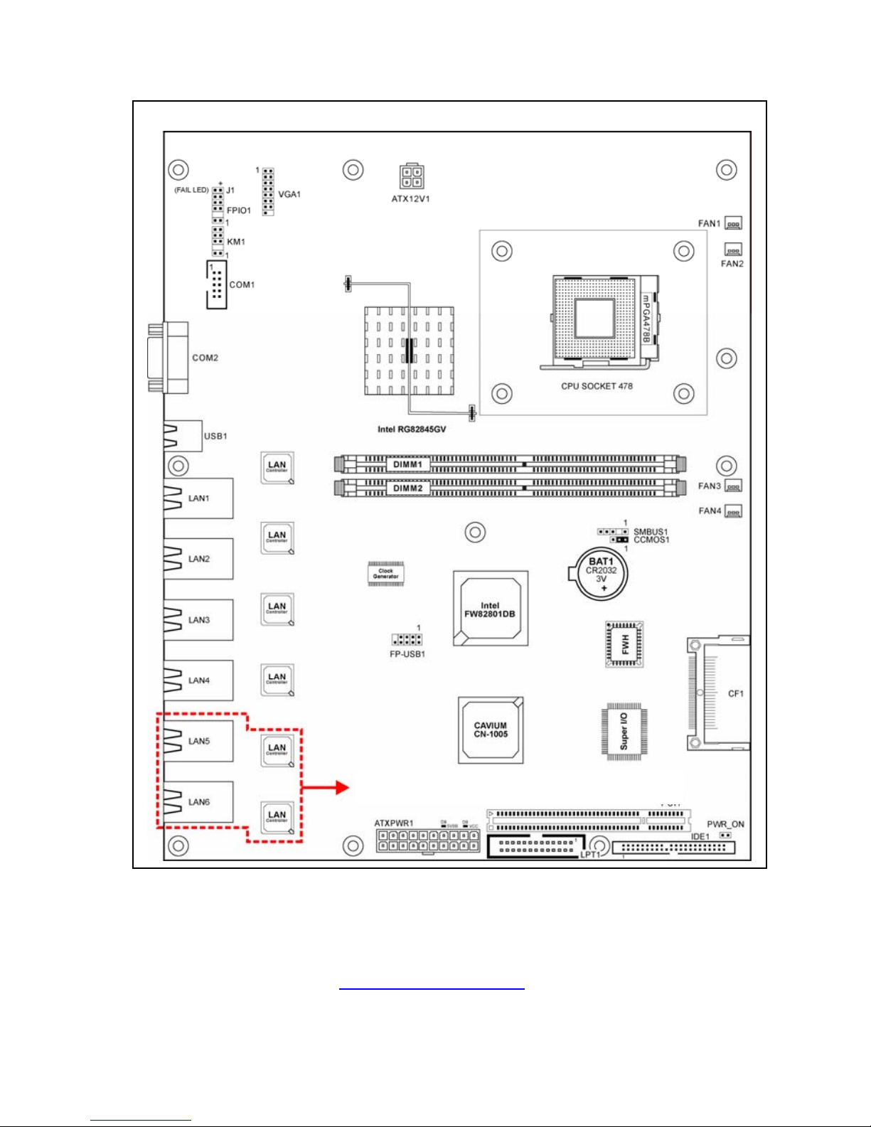
1.2 Layout
For S6601V2E4H, S6601E6H only
Page 6

http://www.TYAN.com
6
1.3 Jumpers & Connectors Description
Jumpers Description Default Setting
CCMOS1 CMOS Clearing Header
Pins 1-2 Close
(Normal)
Connectors Description
ATXPWR1/ATX12V1 ATX12V Power Connectors
CF1 Compact Flash Memory Card Reader Socket
COM1 Additional COM Port Connection Header
COM2 COM Port Connector
DIMM1/DIMM2 DDR DIMM Slots
FAN1/FAN2/FAN3
Fan Power Connector with Speed Monitoring
Support
FAN4
Fan Power Connector without Speed Monitoring
Support
FPIO1
Front Panel Switches & Indicators Connection
Headers
FP-USB1 Additional USB Port Connection Header
IDE1 IDE Disk Drive Connector
J1 System-fail LED Connection Header
KM1 External Keyboard/Mouse Connection Head er
LAN1/LAN2
S6601V2E4H: 10/100/1000Mbps LAN connectors.
S6601E4H, S6601E6H: 10/100Mbps LAN
connectors.
LAN3~LAN6 10/100Mbps LAN Connectors
PCI1 PCI Expansion Slot
PWR_ON
External Power-On switch Connection Header
SMBUS1 System Management Bus Connection Header
USB1 External USB Port Connector
VGA1 VGA Output Connection Header
Page 7
http://www.TYAN.com
7
Chapter 2: Hardware Setup
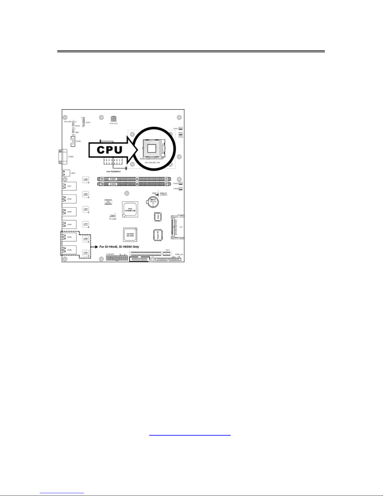
2.1 CPU Socket
This server board provides one 478-pin Zero Insertion Force (Z IF) socket to
install the Intel Pentium 4 CPU.
Page 8
http://www.TYAN.com
8
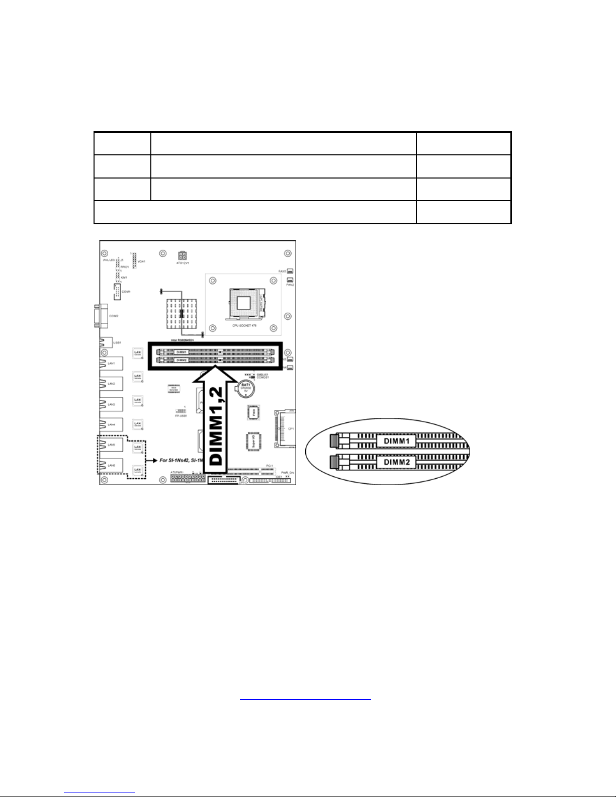
2.2 System Memory
This server board provides two 184-pin DDR DIMM slots for un-buffered an d
non-ECC modules with memory size expansible up to 2GB
(DDR333/266/DDR200).
DIMM DIMM Module Total Memory
1 256MB, 512MB, 1GB 256MB ~ 1GB
2 256MB, 512MB, 1GB 256MB ~ 1GB
Total System Memory
256MB ~ 2GB
Page 9
http://www.TYAN.com
9
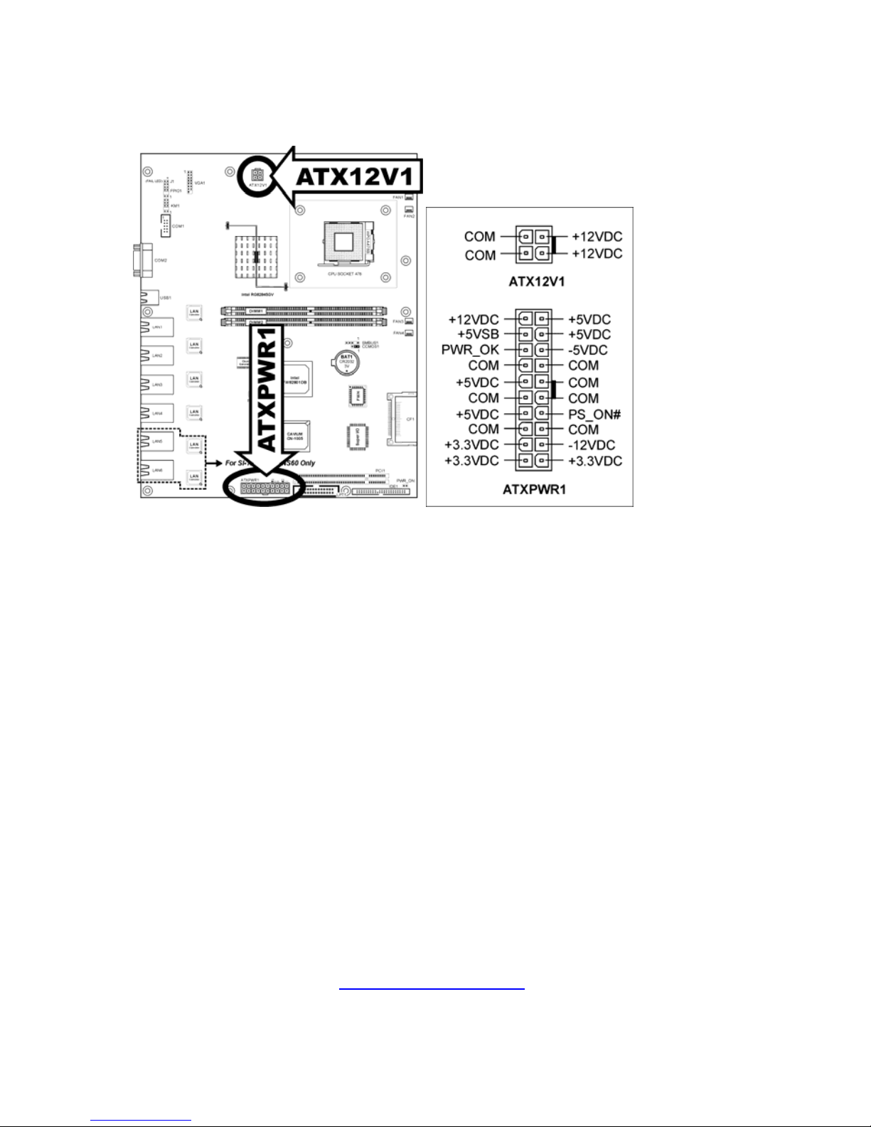
2.3 Power Connectors
These two connectors connect to ATX12V power supply.
Page 10
http://www.TYAN.com
10
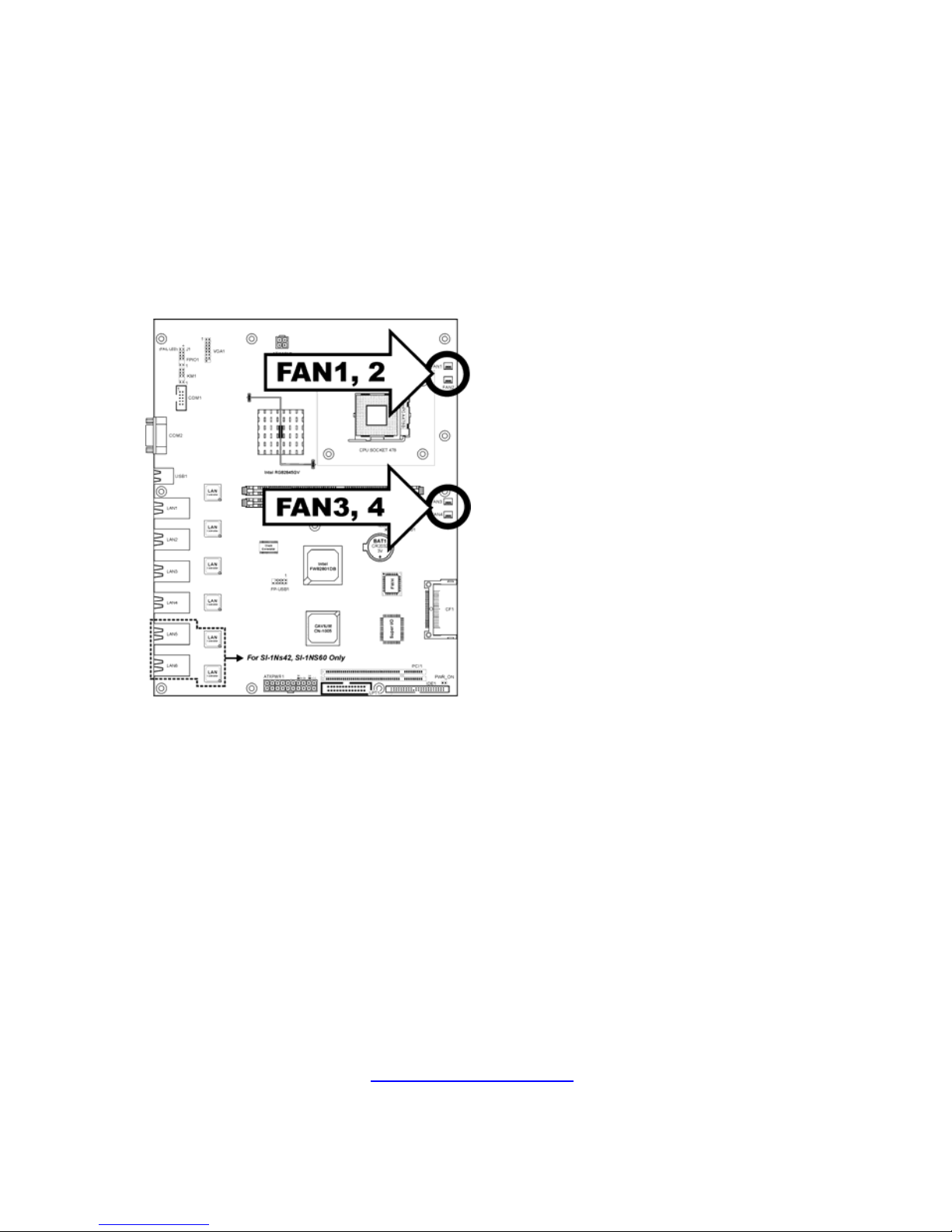
2.4 FAN Connectors
These 3-pin connectors each provide power to the cooling fans installed in your
system.
• FAN1/FAN2/FAN3: With speed monitoring support in BIOS menu
• FAN4: Without speed monitoring support in BIOS menu
WARNING: These fan connectors are
not jumpers. DO NOT place jumper
caps on these connectors.
Page 11
http://www.TYAN.com
11
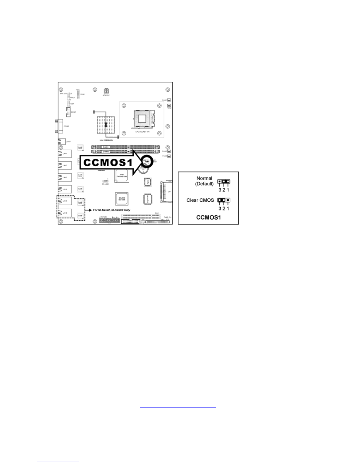
2.5 CMOS Memory Clearing Header
This header uses a jumper cap to clear the CMOS memory.
• Pin 1-2 shorted (default): Normal operation.
• Pin 2-3 shorted: Clear CMOS memory.
ATTENTION: Turn the system power off
first (including the +5V standby power)
before clearing the CMOS memory.
Page 12
http://www.TYAN.com
12
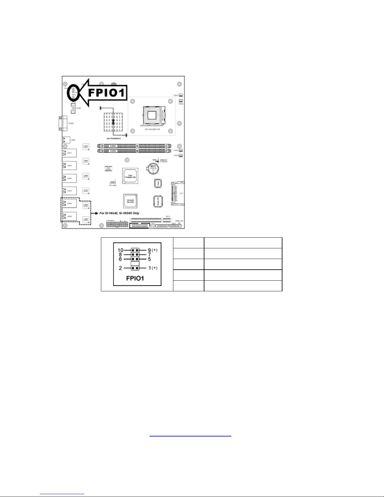
2.6 Front Panel Switches & Indicators Connection
Headers
This header provides connection to external switches and indicators.
Pin Definition
1-2 S.LED
5-6 Reset
7-8 Chassis Intrusion
9-10 HD LED
Page 13
http://www.TYAN.com
13
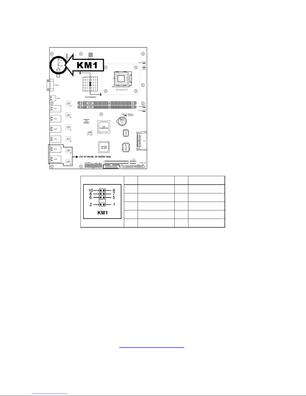
2.7 External Keyboard/Mouse Connection Header
This header provides the external connection to keyboard and mouse.
Pin Definition Pin Definition
1 VCC 2 VCC
3 NC 4 NC
5 KB Data 6 Mouse Data
7 Ground 8 Ground
9 KB Clock 10 Mouse Clock
Page 14
http://www.TYAN.com
14
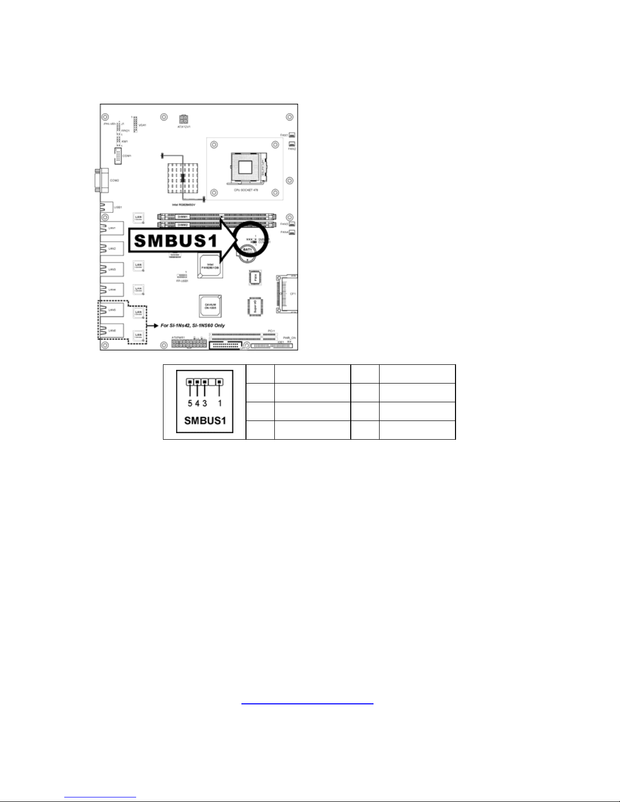
2.8 System Management Bus Connection Header
This header provides the connection to system management bus (SMBus).
Pin Definition Pin Definition
1 SMBCLK 4 SMBDATA
3 Ground
5 VCC
Page 15
http://www.TYAN.com
15
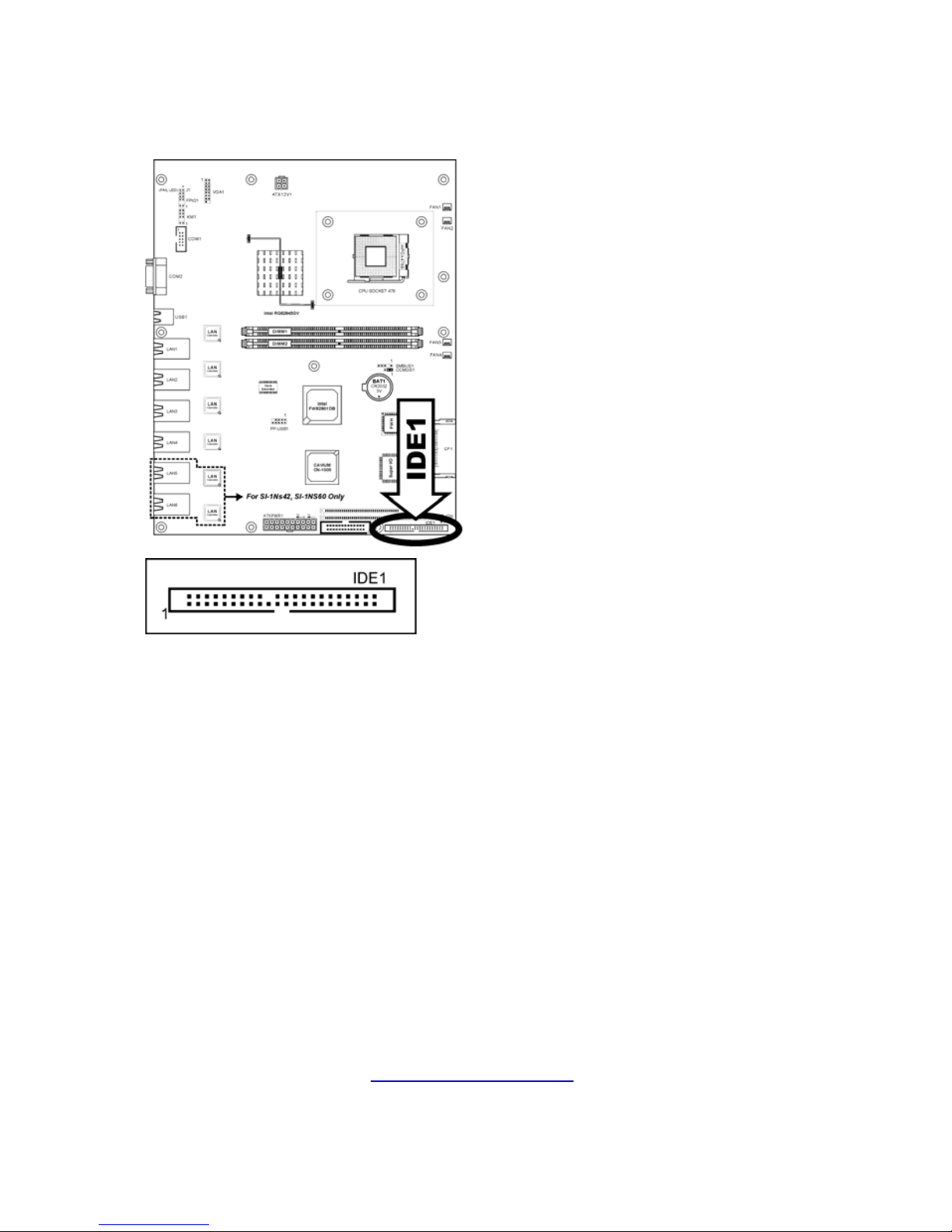
2.9 IDE Disk Drive Connector
This connector provides IDE hard drive connection (Pitch 2.5).
Page 16
http://www.TYAN.com
16
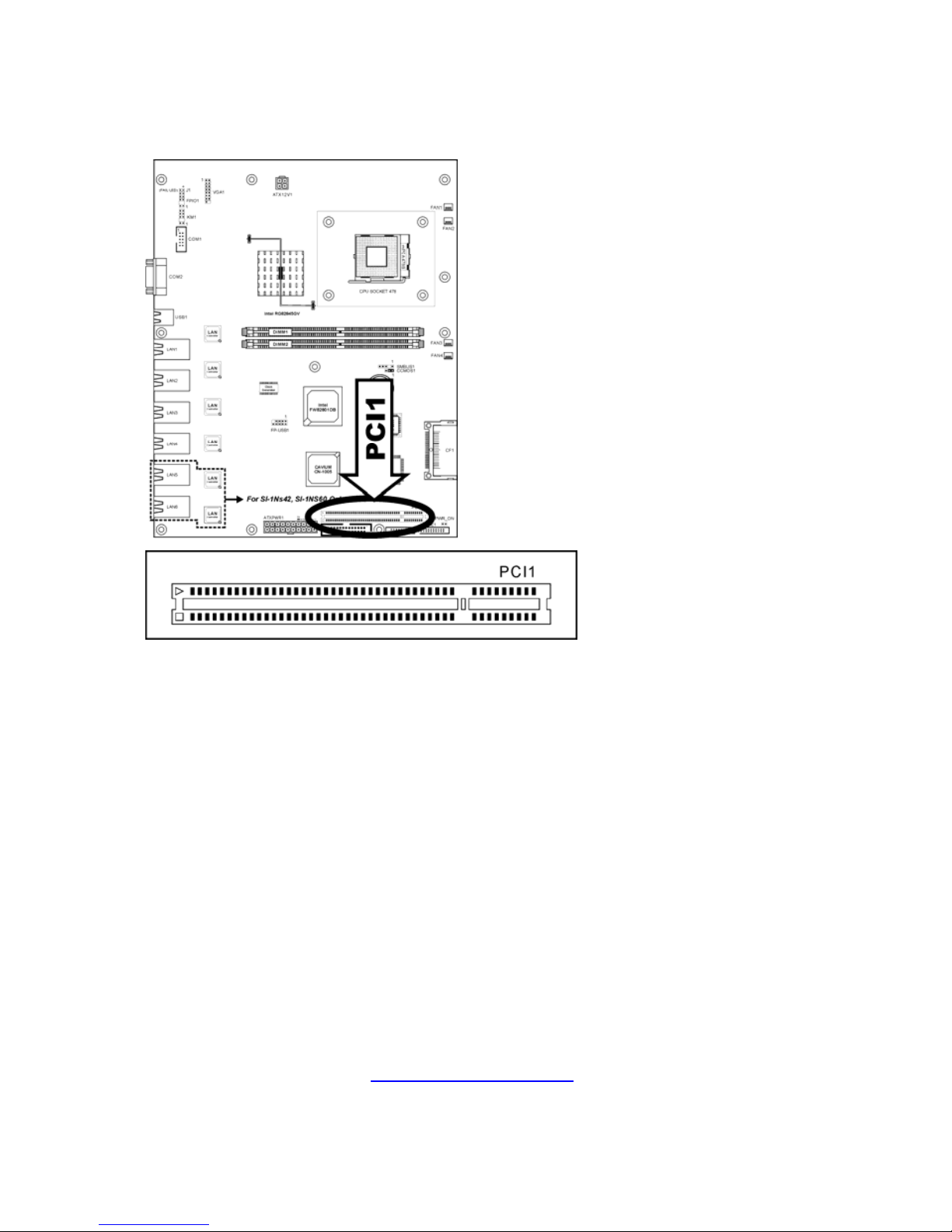
2.10 PCI Expansion Slot
This slot provides one 32bit/33MHz PCI add-on-card connection (3.3V).
Page 17
http://www.TYAN.com
17
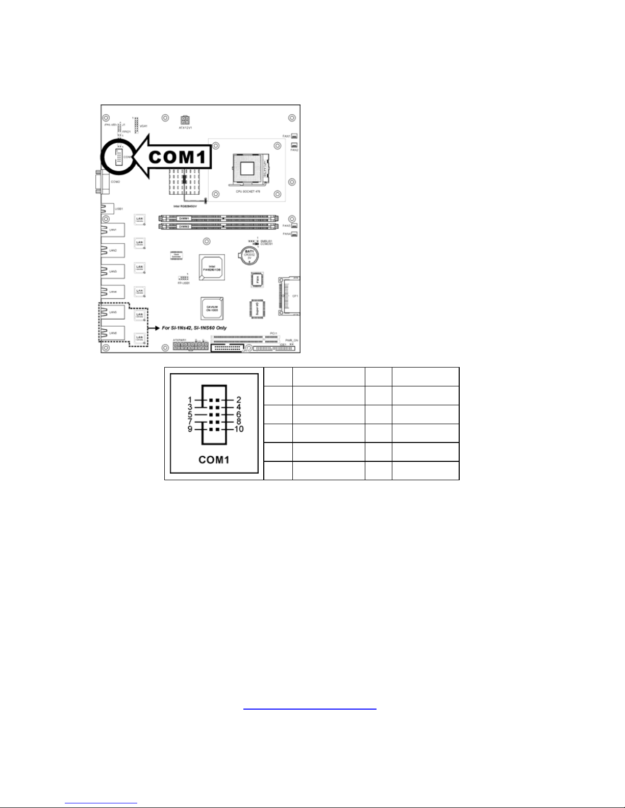
2.11 Additional COM Port Connection Header
This header provides an external COM port connection.
Pin Definition Pin Definition
1 DCDA 2 SINA
3 SOUTA 4 DTRA
5 Ground 6 DSRA
7 RTSA 8 CTSA
9 RIA 10 VCC
Page 18
http://www.TYAN.com
18
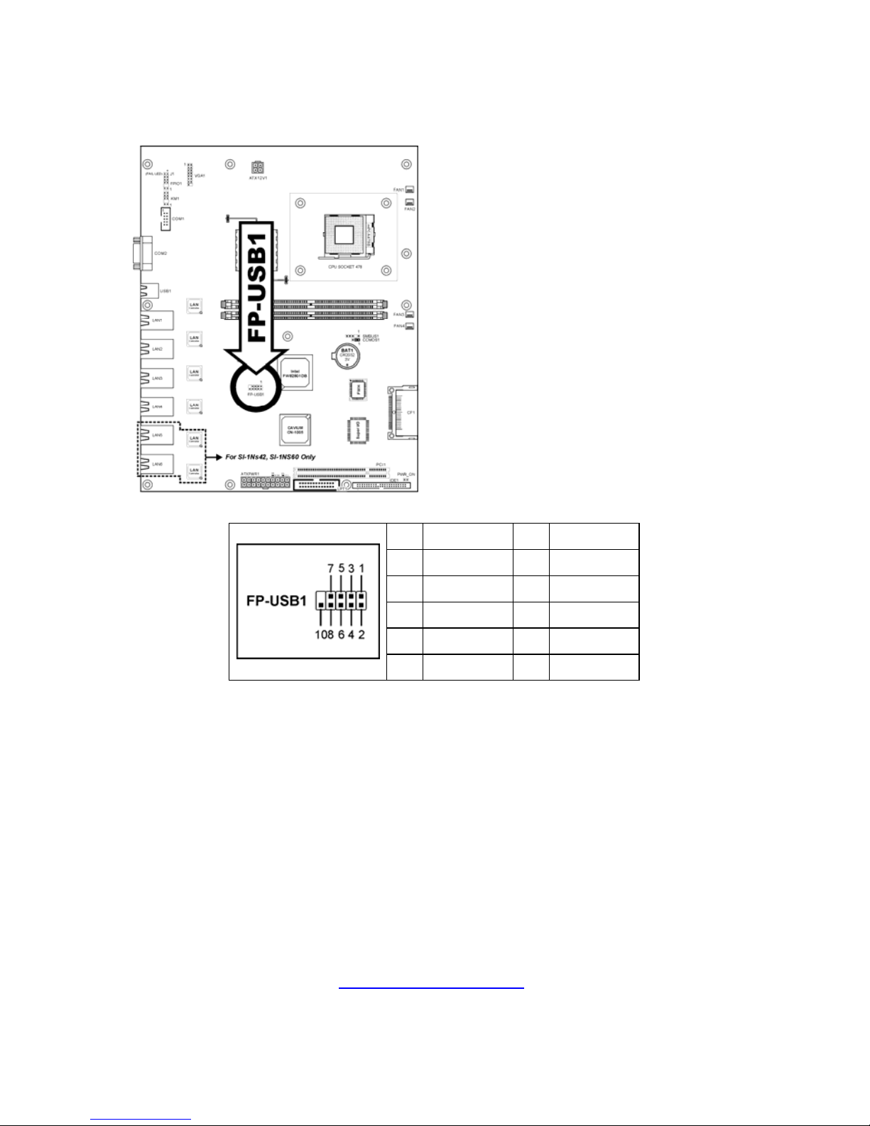
2.12 Additional USB Port Connection Header
This header provides two external USB ports connection.
Pin Definition Pin Definition
1 VCC 2 VCC
3 - Data 0 4 - Data 1
5 + Data 0 6 + Data 1
7 Ground 8 Ground
10 NC
Page 19
http://www.TYAN.com
19
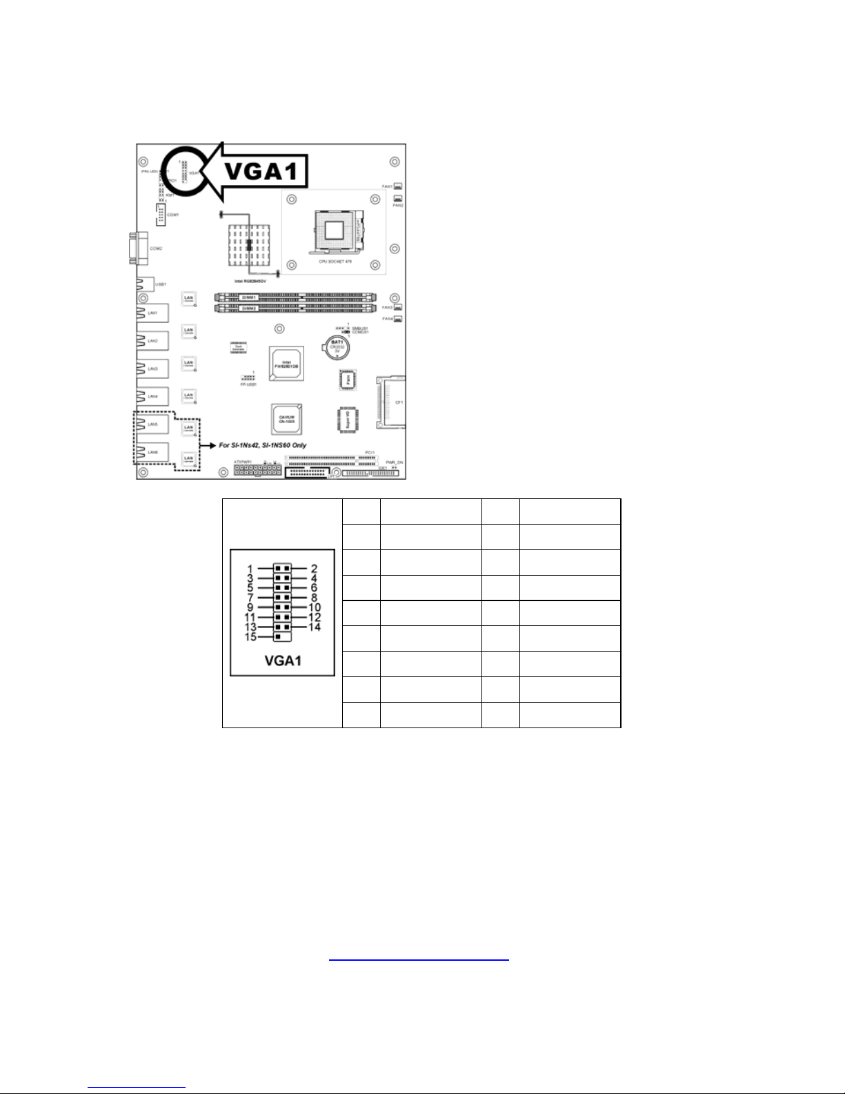
2.13 VGA Output Connection Header
This header provides an external VGA output connection.
Pin Definition Pin Definition
1 Red 2 Green
3 Blue 4 NC
5 Ground 6 Ground
7 Ground 8 Ground
9 VCC 10 Ground
11 NC 12 DDC Data
13 H.SYNC 14 V.SYNC
15 DDC Clock
Page 20
http://www.TYAN.com
20
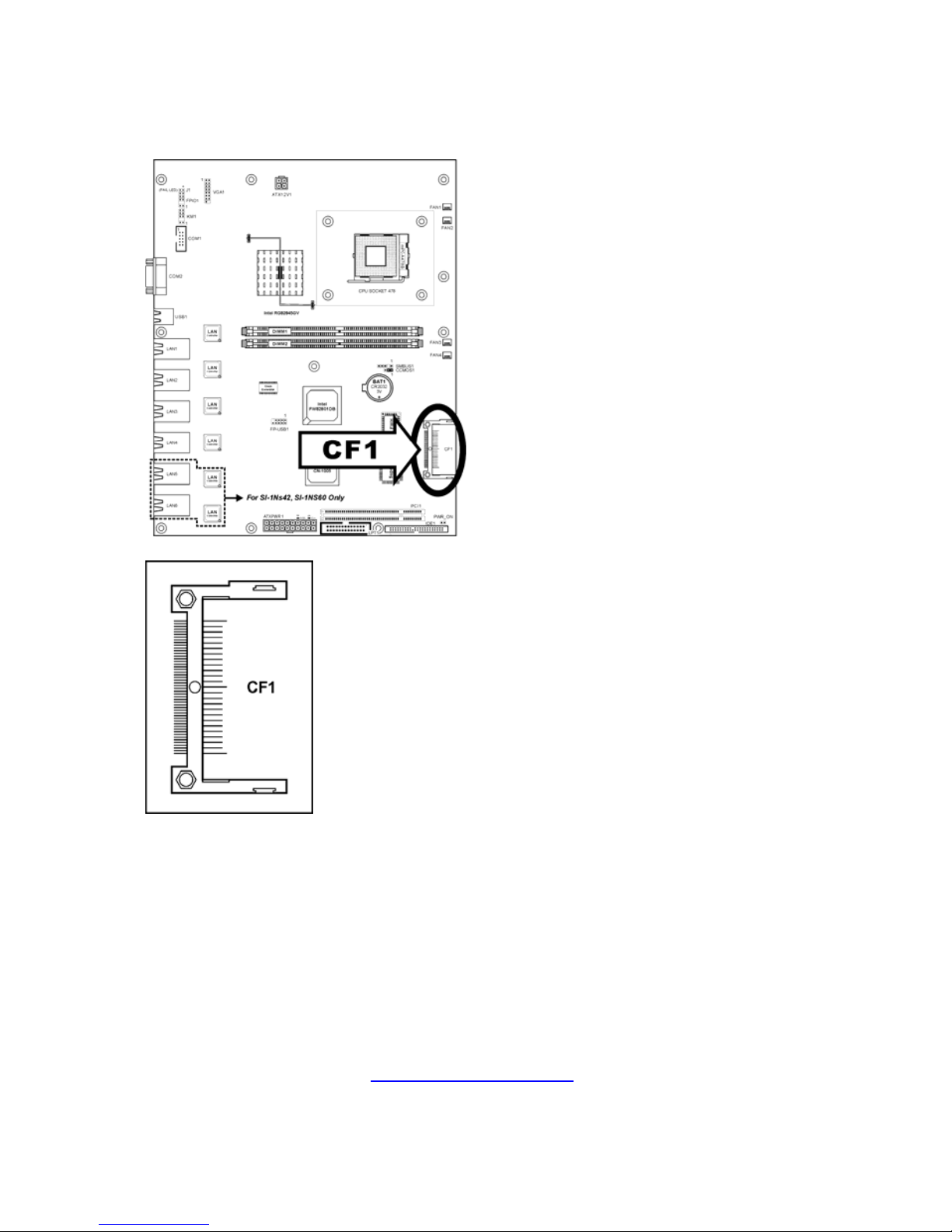
2.14 Compact Flash Memory Card Reader Socket
This socket provides the connection to Compact Flash memory card reader.
Page 21
http://www.TYAN.com
21
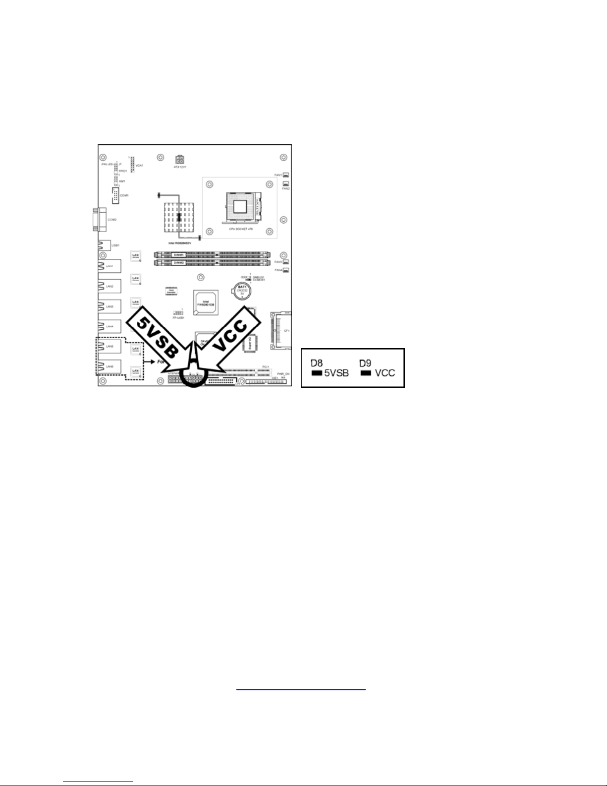
2.15 Status Indicators
• 5VSB: This LED lights up when the power supply is connected with
power source.
• VCC: This LED lights up when the system power is on.
Page 22
http://www.TYAN.com
22
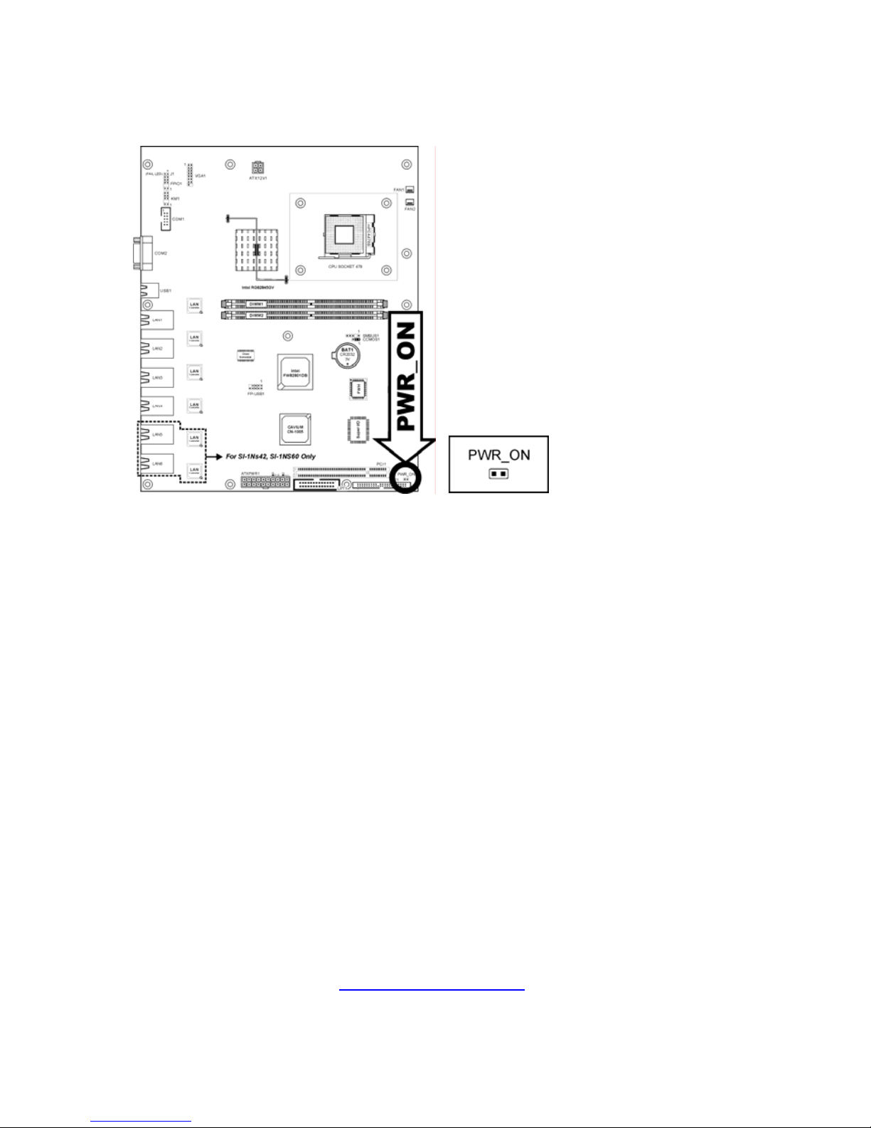
2.16 Power-On Switch
This header provides the connection to external Power-On switch.
Page 23
http://www.TYAN.com
23
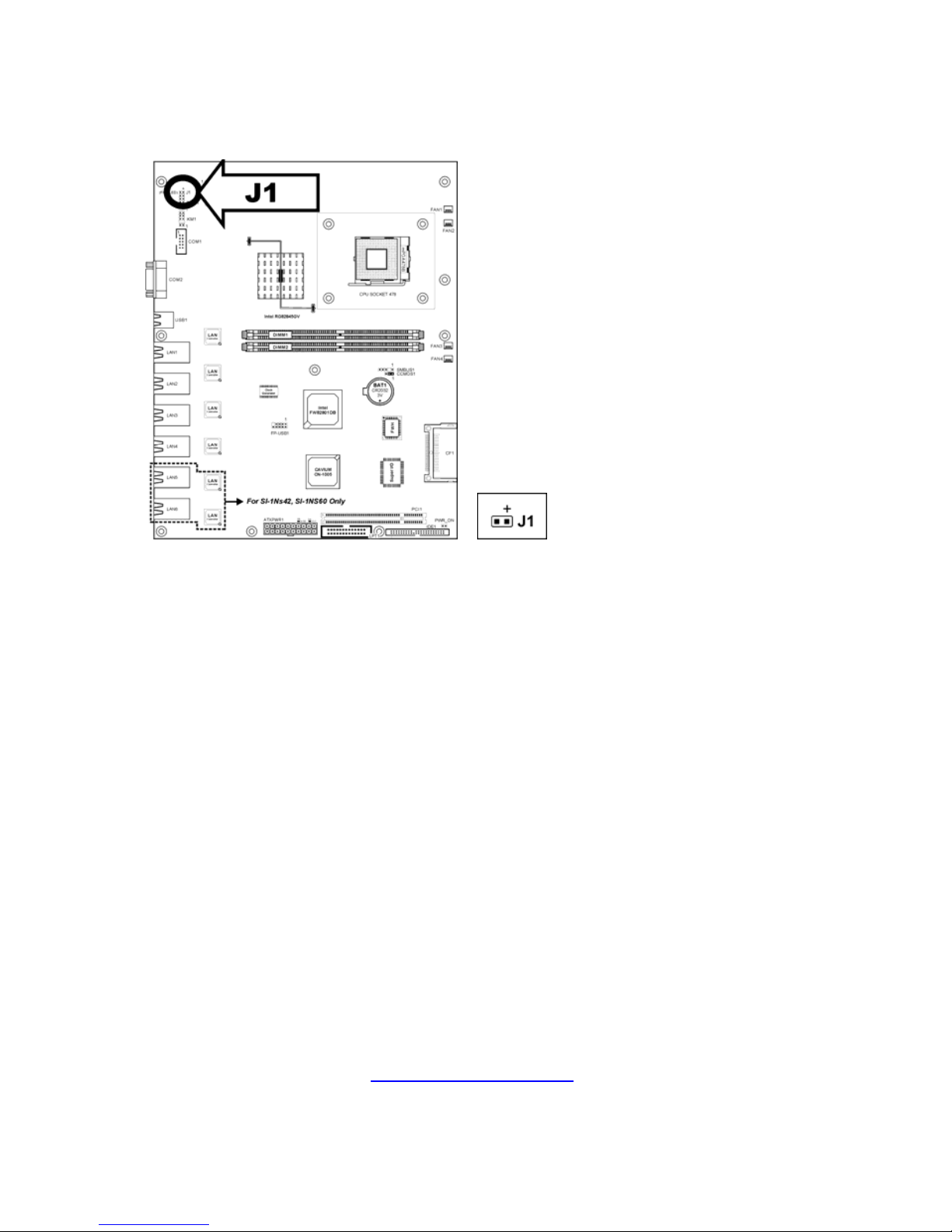
2.17 System-fail LED Connection Header
This header provides the connection to system-fail LED.
Page 24
http://www.TYAN.com
24
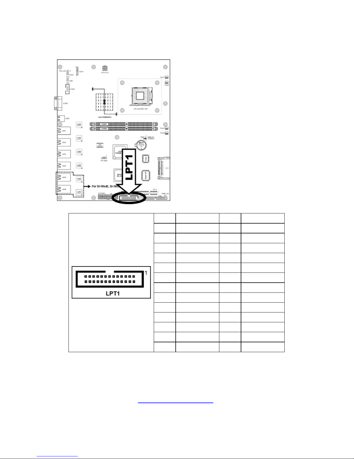
2.18 Parallel Port Header
This connector provides one parallel port connection.
Pin Definition Pin Definition
1 STB# 2 AFD#
3 PD0 4 ERR#
5 PD1 6 INIT#
7 PD2 8 SLIN#
9 PD3 10 GND
11 PD4 12 GND
13 PD5 14 GND
15 PD6 16 GND
17 PD7 18 GND
19 ACK# 20 GND
21 BUSY 22 GND
23 PE 24 GND
25 SLCT 26 GND
Page 25
http://www.TYAN.com
25
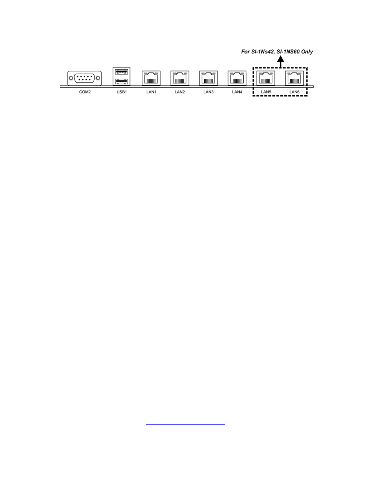
2.19 External I/O Panel Connectors
• COM2: Connects to external modem, serial mouse or other devices that
supports this communication protocol.
• USB1: USB 2.0 connectors.
• LAN1/LAN2:
10/100/1000Mbps LAN connectors (S6601V2E4H)
10/100Mbps LAN connectors (S6601E4H, S6601E6H)
• LAN3~LAN6: 10/100Mbps LAN connectors.
Page 26

http://www.TYAN.com
26
Memo
Page 27
http://www.TYAN.com
27
Chapter 3: BIOS Setup
This motherboard provides a programmable EEPROM that you can update the
BIOS utility. The BIOS (Basic Input/Output System) is a program that deals with
the basic level of communication between processor and periphera ls. Use the
BIOS Setup program only when installing motherboard, reconfiguring s ystem, or
prompted to “Run Setup”. This chapter explains the Setup Utility of BIOS utility.
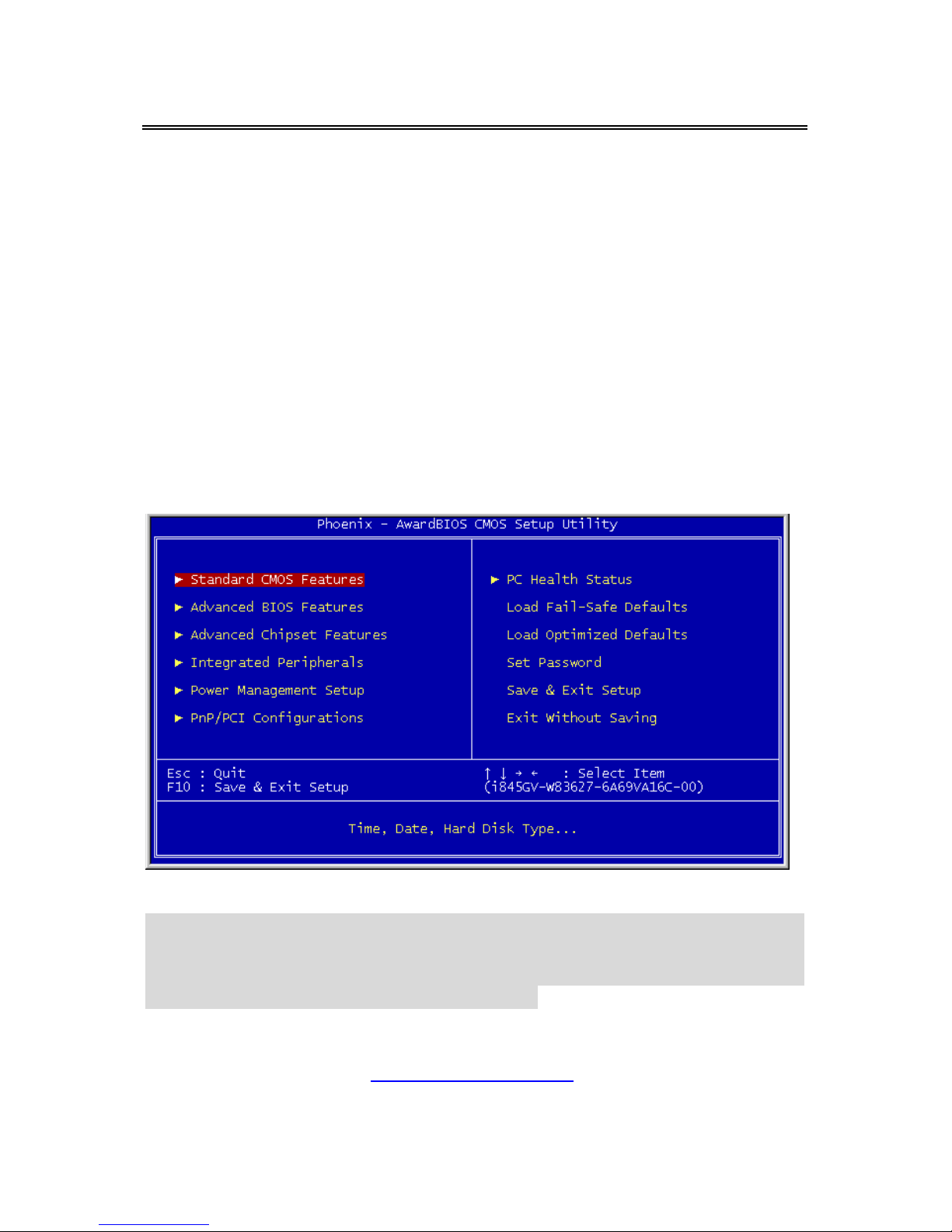
After powering up the system, the BIOS message appears on the screen, the
memory count begins, and then the following message appears on the screen:
Press DEL to run setup
If this message disappears before you respond, restart the system by pressing
<Ctrl> + <Alt> + <Del> keys, or by pressing the Reset button on computer
chassis. Only when it failed by these two methods can you restart the system by
powering it off and then back on.
After pressing <Del> key, the main menu screen appears.
NOTE: In order to increase system stability and performance, our engineering
staffs are constantly improving the BIOS menu. The BIOS setup screens and
descriptions illustrated in this manual are for your reference only, may not
completely match what you see on your screen.
Page 28
http://www.TYAN.com
28
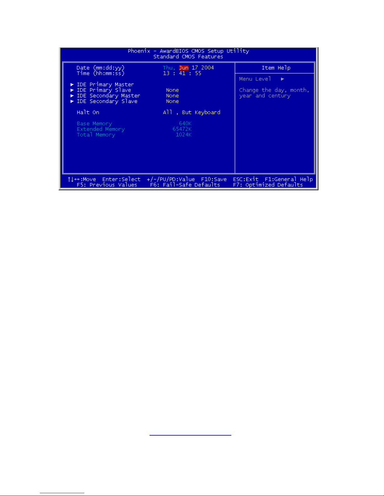
3.1 Standard CMOS Features
Date (mm:dd:yy)
This item sets the date you specify (usually the current date) in the format of
[Month], [Date], and [Year].
Time (hh:mm:ss)
This item sets the time you specify (usually the current time) in the format of
[Hour], [Minute], and [Second].
Page 29
http://www.TYAN.com
29
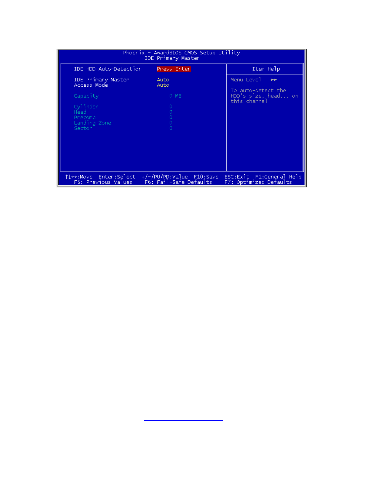
ª IDE Primary Master, IDE Primary Slave
Click <Enter> key to enter its submenu:
IDE HDD Auto-Detection
This item allows you to detect the parameters of IDE drives by pressing the
<Enter> key. The parameters will automatically be shown on the screen.
IDE Primary Master
When set to [Auto], the BIOS will automatically check what kind of IDE drive you
are using. If you want to define your own drive by yourself, set it to [Manual] and
make sure you fully understand the meaning of the parameters. Refer to the
manual provided by the device manufacturer to get the settings right.
Access Mode
This item selects the mode to access your IDE devices. Leave this item to its
default [Auto] settings to let BIOS detects the access mode of your HDD and
makes decision automatically.
Capacity
This item automatically displays your HDD size. Note that this size is usually
slightly greater than the size given by a disk-checking program of a formatted
disk.
Cylinder
This item configures the numbers of cylinders.
Head
This item configures the numbers of read/write heads.
Page 30

http://www.TYAN.com
30
Precomp
This item displays the number of cylinders at which to change the write timing.
Landing Zone
This item displays the number of cylinders specified as the landing zone for the
read/write heads.
Sector
This item configures the numbers of sectors per track.
ª Back to Standard CMOS Features Setup Menu
Halt On
This item determines whether the system stops if an error is detected during
system boot-up.
[All Errors]: The system-boot will stop whenever the BIOS detect a non-fatal
error.
[No Errors]: The system-boot will not stop for any error detected.
[All, But Keyboard]: The system-boot will stop for all errors but keyboard error.
Base Memory
This item displays the amount of base memory installed in the system. The
value of the base memory is typically 640K for system with 640K or more
memory size installed on the motherboard.
Extended Memory
This item displays the amount of extended memory detected during system
boot-up.
Total Memory
This item displays the total memory available in the system.
Page 31
http://www.TYAN.com
31
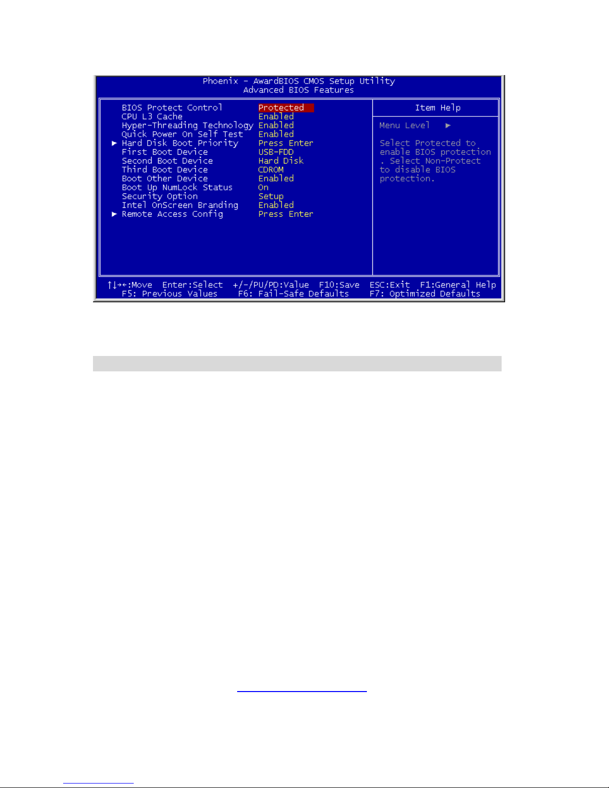
3.2 Advanced BIOS Features
BIOS Protect Control
This option protects for accidentally BIOS writing attempt.
NOTE: Make sure to set this item to “Non-Protect” when flashing the BIOS.
CPU L3 Cache:
This item is used to enable the L3 cache (default setting), and appears onl y for
certain CPU (Intel Pentium 4 processor with HT Technology Extreme Edition)
that possesses L3 cache.
Hyper-Threading Technology
This item is used to enable the functionality of the processor with HyperThreading Technology and will appear only when using such processor.
The Hyper-Threading Technology helps yo ur PC work more efficiently by
maximizing processor resources and enabling a single processor to run two
separate threads of software simultaneously, bringing forth greater performance
and system responsiveness when running multiple applications at once.
Quick Power On Self Test
When set to [Enabled], this item speeds up the Power On Self Test (POST)
after powering on the system. The BIOS shorten or skip some check during the
POST.
Page 32

http://www.TYAN.com
32
Hard Disk Boot Priority
This item selects the hard disks booting priority. By pressing <Enter> key, you
can enter its submenu where the hard disks detected can be selected for the
booting sequence to boot up system.
This item functions only when there is the option of [Hard Disk] in any one of the
First/Second/Third Boot Device items.
First Boot Device / Second Boot Device / Third Boot Device / Boot Other
Device
Select the drive to boot first, second and third in the [First Boot Device],
[Second Boot Device], and [Third Boot Device] fields respectively. The BIOS will
boot the operating system according to the sequence of the drive selected. Set
[Boot Other Device] to [Enabled] if you wish to boot from another device other
than these three items.
Boot Up NumLock Status
This item determines the default state of the numeric keypad at system booting
up.
[On]: The numeric keypad functions as number keys.
[Off]: The numeric keypad functions as arrow keys.
Security Option
This item determines when the system will prompt for password - every time the
system boots or only when enters the BIOS setup.
[Setup]: The password is required only when accessing the BIOS Setup.
[System]: The password is required each time the computer boots up.
NOTE: Don’t forget your password. If you forg et the password, you will h ave
to open the computer case and clear all information in the CMOS before you
can start up the system. But by doing this, you will have to reset all previously
set options.
Intel OnScreen Branding:
This item determines whether to display the “Intel Inside” logo or not at system
boots up.
Page 33
http://www.TYAN.com
33
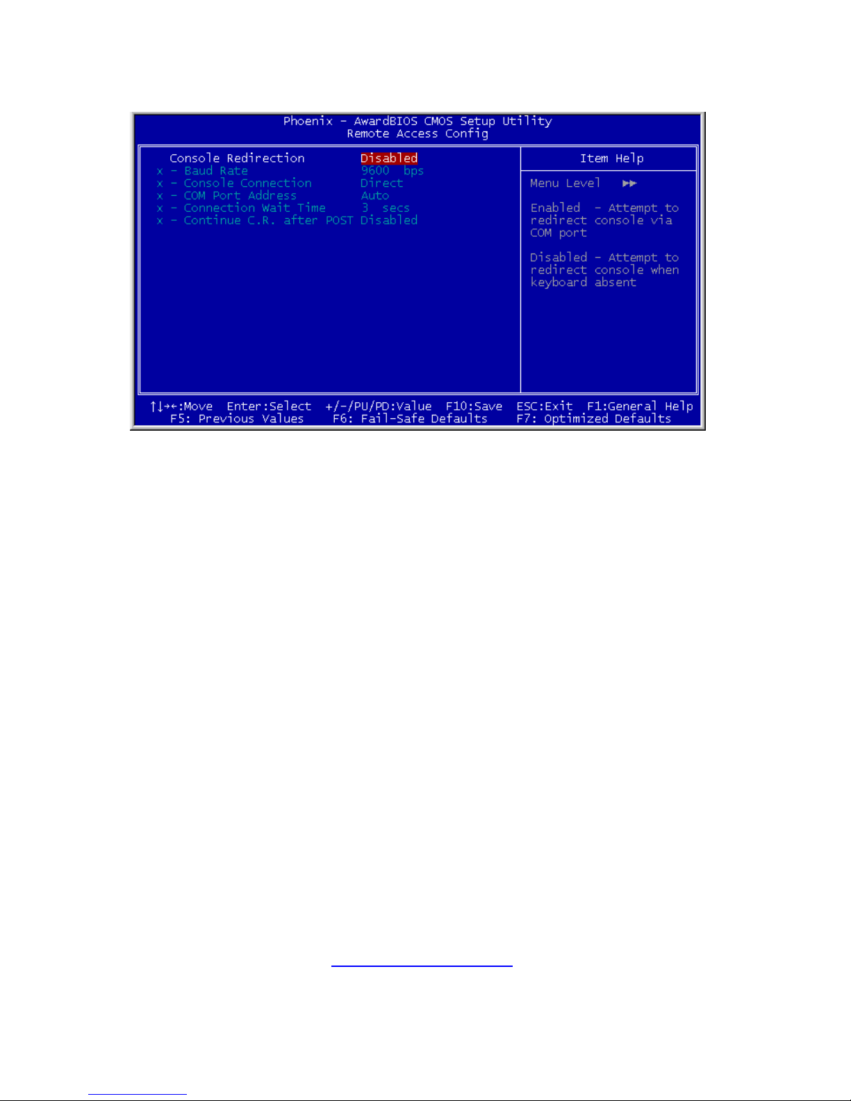
ª Remote Access Config:
Click <Enter> key to enter its submenu:
Console Redirection:
[Enabled]: Attempt to redirect console via COM port.
[Disabled]: Attempt to redirect console when keyboard absent.
Page 34
http://www.TYAN.com
34
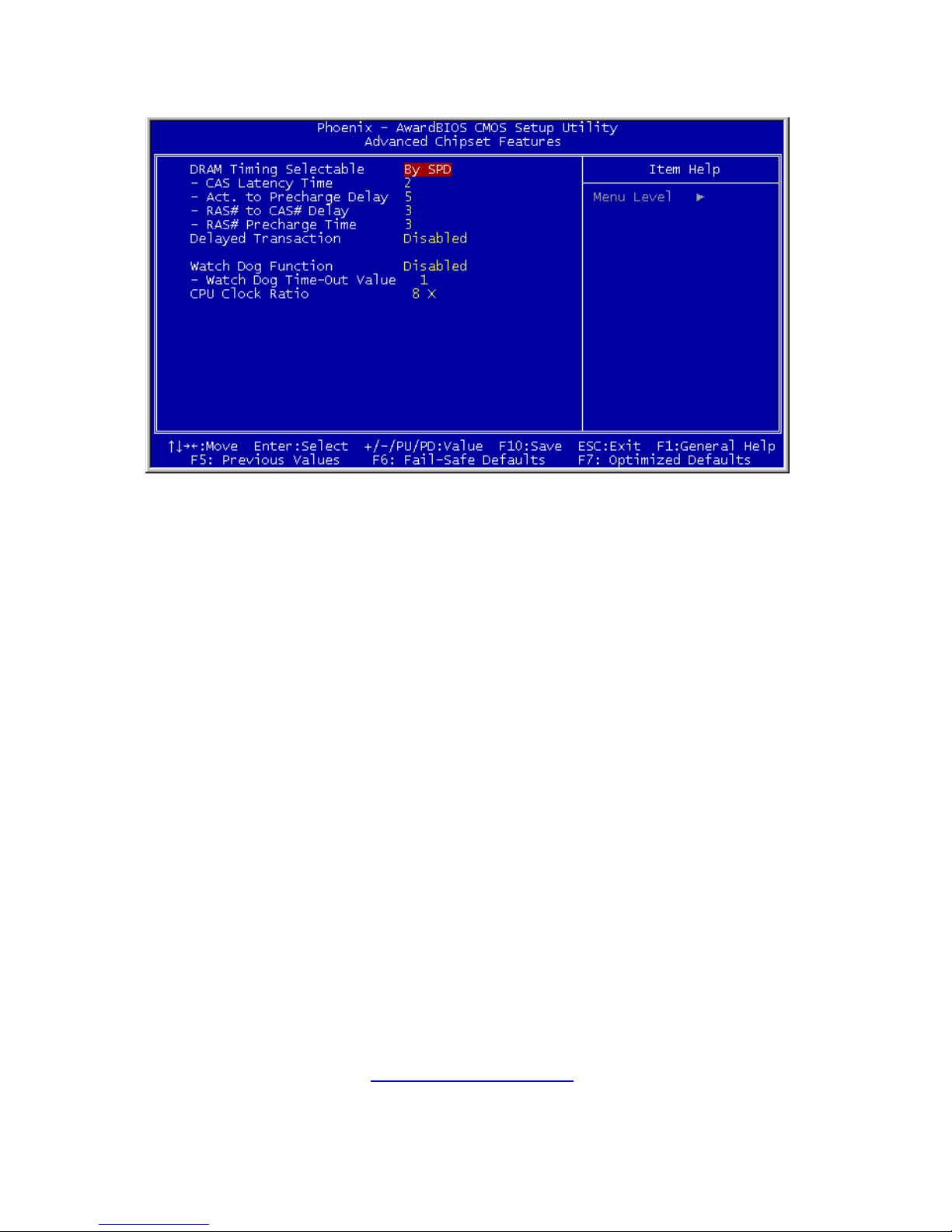
3.3 Advanced Chipset Features
DRAM Timing Selectable:
This item sets the optimal timings for the following four items, depending on the
memory module you are using. The default setting “By SPD” configures these
four items by reading the contents in the SPD (Serial Presence Detect) device.
The EEPROM on the memory module stores critical parameter information
about the module, such as memory type, size, speed, voltage interface, and
module banks.
CAS Latency Time:
This item controls the latency between the DRAM read command a nd the time
that the data becomes actually available.
Act to Precharge Delay:
This item controls the number of DRAM clocks used for the DRAM parameters.
DRAM RAS# to CAS# Delay
This item controls the latency between the DRAM active command and the
read/write command.
DRAM RAS# Precharge:
This item controls the idle clocks after issuing a precharge command to the
DRAM.
Delayed Transaction
When set to [Enabled], the PCI bus will be freed up when the CPU is accessing
8-bit ISA cards. This will allow PCI and ISA buses to be used more efficiently
Page 35

http://www.TYAN.com
35
and prevents performance dropping on the PCI bus. This process normally
consumes about 50-60 PCI clocks without PCI delayed transaction. Leave this
item to its default [Disabled] setting when using ISA cards that are not PCI 2.1
compliant.
Watch Dog Function
This option controls the function for Watch Dog.
[Disabled]: Disable the Watch Dog function.
[Enabled/Sec.]: Enable the Watch Dog function by t he timer based on seconds.
[Enabled/Min.]: Enable the Watch Dog function by the timer based on minutes.
Watch Dog Time-Out Value
Type in the Time-Out value for your Watch Dog function.
CPU Clock Ratio
This item selects the multiplier factors for your CPU if it is not locked.
Page 36
http://www.TYAN.com
36
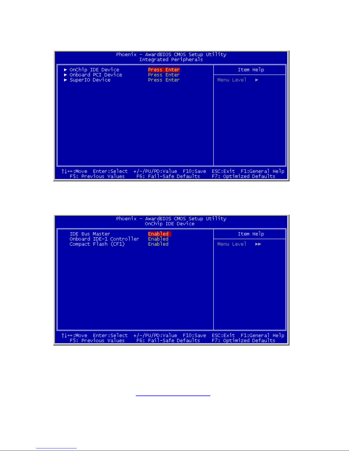
3.4 Integrated Peripherals
ª OnChip IDE Device:
Click <Enter> key to enter its submenu:
IDE Bus Master:
This option enables or disables the IDE bus mastering capability under the DOS
environment.
Page 37
http://www.TYAN.com
37
Onboard IDE-1 Controller
This item enables or disables the onboard IDE-1 controller.
Compact Flash (CF1)
This item enables or disables the onboard CF1 control ler.
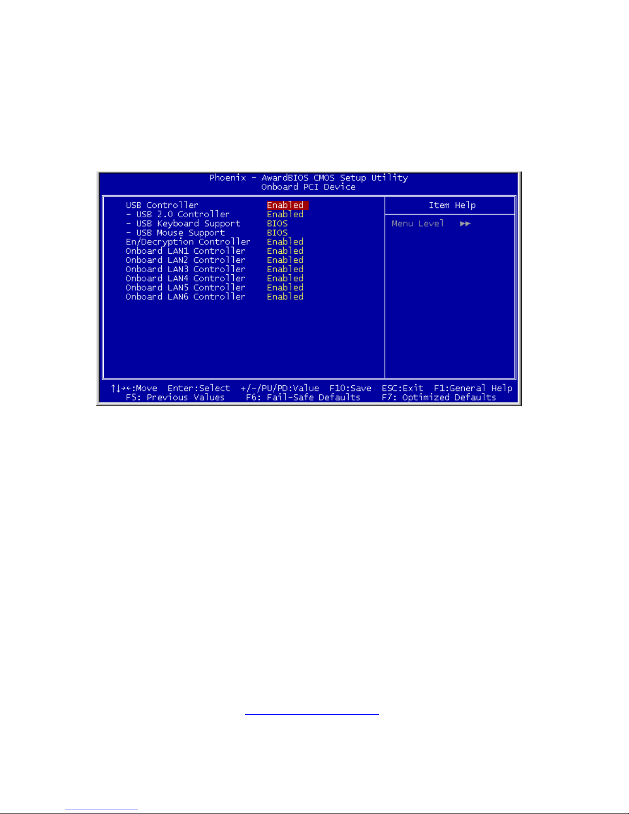
ª Onboard PCI Device:
Click <Enter> key to enter its submenu:
USB Controller:
This option enables or disables the USB controller.
USB 2.0 Controller:
This option enables or disables the USB 2.0 controller.
USB Keyboard Support:
This item allows you to select [BIOS] for using USB keyboard in DOS
environment, or [OS] in OS environment.
USB Mouse Support:
This item allows you to select [BIOS] for using USB mouse in DOS environment,
or [OS] in OS environment.
En/Decryption Controller:
This option enables or disables the onboard Encryption/Decryption Controller.
Onboard LAN1 Controller:
This option enables or disables the LAN1 controller.
Page 38
http://www.TYAN.com
38
Onboard LAN2 Controller:
This option enables or disables the LAN2 controller.
Onboard LAN3 Controller:
This option enables or disables the LAN3 controller.
Onboard LAN4 Controller:
This option enables or disables the LAN4 controller.
Onboard LAN5 Controller: (For SI-1Ns42, SI-1Ns60 only)
This option enables or disables the LAN5 controller.
Onboard LAN6 Controller: (For SI-1Ns42, SI-1Ns60 only)
This option enables or disables the LAN6 controller.
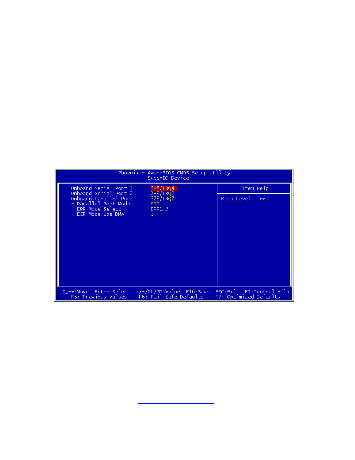
ª SuperIO Device:
Click <Enter> key to enter its submenu:
Onboard Serial Port 1:
This item determines which I/O addresses the onboard Serial Port 1 controller
will access.
[Auto]: The system automatically select an I/O address for the onboard Serial
Port 1.
[3F8/IRQ4, 2F8/IRQ3, 3E8/IRQ4, 2E8/IRQ3]: Allows you to manually select an
I/O address for the onboard Serial Port 1.
[Disabled]: Disables the onboard Serial Port 1.
Page 39

http://www.TYAN.com
39
Onboard Serial Port 2:
This item determines which I/O addresses the onboard Serial Port 2 controller
will access.
[Auto]: The system automatically select an I/O address for the onboard Serial
Port 2.
[3F8/IRQ4, 2F8/IRQ3, 3E8/IRQ4, 2E8/IRQ3]: Allows you to manually select an
I/O address for the onboard Serial Port 2.
[Disabled]: Disables the onboard Serial Port 2.
Onboard Parallel Port:
This item specifies the I/O address used by the parallel port.
[Disabled]: This option prevents the parallel port from accessing any system
resources. When the value of this option is set to [Disabled], the printer port
becomes unavailable.
[378/IRQ7]: This option allows the parallel port to use [378/IRQ7] as its I/O port
address. The majority of parallel ports on computer systems use IRQ7 and I/O
Port 378H as the standard setting.
[278/IRQ5]: This option allows the parallel port to use [278/IRQ5] as its I/O port
address.
[3BC/IRQ7]: This option allows the parallel port to use [3BC/IRQ7] as its I/O
port address.
Parallel Port Mode:
This item specifies the parallel port mode.
[Normal]: Allows the standard parallel port mode to be used.
[SPP]: (Standard Parallel Port) Allows bi-directional parallel port operation at
normal speed.
[EPP]: (Enhanced Parallel Port) Allows bi-directional parallel port oper ation at
maximum speed.
[ECP]: (Extended Capabilities Port) Allows bi-directional par allel port operation
at a speed faster than the normal mode’s data transfer rate.
[ECP+EPP]: Allows parallel port operation at ECP and EPP mode.
EPP Mode Select:
This item selects the EPP mode.
ECP Mode Use DMA:
This item selects the DMA channel of the parallel port.
Page 40
http://www.TYAN.com
40
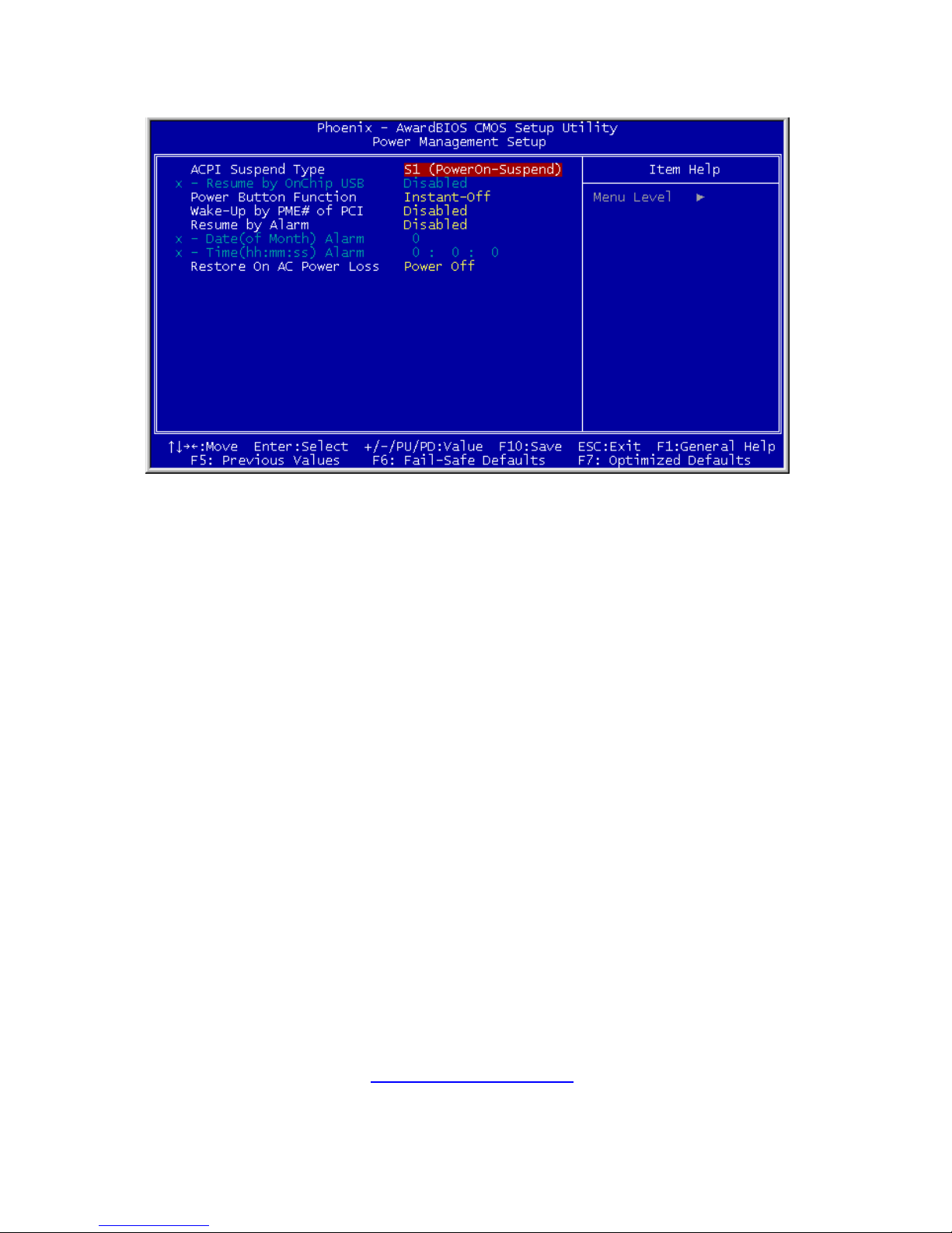
3.5 Power Management Setup
ACPI Suspend Type:
This item selects the type of Suspend mode.
[S1 (PowerOn-Suspend)]: Enables the Power On Suspend function.
[S3 (Suspend-To-RAM)]: Enables the Suspend to RAM function.
Resume by OnChip USB:
When set to [Enabled], this item allows you to use a USB device to wake up a
system that is in the S3 (STR - Suspend To RAM) state. This item can be
configured only if the item “ACPI Suspend Type” is set to [S3(STR)].
Power Button Function
This item selects the method of powering off your system:
[Delay 4 Sec.]: Pushing the power button for more than 4 seconds will power
off the system. This will prevent the system from powering off in case you
accidentally hit or pushed the power button.
[Instant-Off]: Pressing and then releasing the power button at once will
immediately power off the system.
Wake-Up by PME# of PCI:
When set to [Enabled], access to the onboard LAN or a PCI card such as a
modem or LAN card will cause the system to wake up. The PCI card must
support the wake up function.
Page 41

http://www.TYAN.com
41
Resume by Alarm:
When set to [Enabled], you can set the date and time you would like the SoftOff PC to power-on in the “Date (of Month) Alarm” and “Time (hh:mm:ss)
Alarm” items. However, if the system is being accessed by incoming calls or
the network (Resume On Ring/LAN) prior to the date and time set in these
items, the system will give priority to the incoming calls or network instead.
Date (of Month) Alarm
[0]: This option power-on the system everyday according to the time set in the
“Time (hh:mm:ss) Alarm” item.
[1-31]: This option selects a date you would like the system to po wer-on. The
system will power-on on the date set, and the time set in the “Time (hh:mm:ss)
Alarm” item.
Time (hh:mm:ss) Alarm
This item sets the time you would like the system to power-on.
Restore On AC Power Loss
This item selects the system action after an AC power failure.
[Power Off]: When power returns after an AC power failure, the system’s
power remains off. You must press the Power button to power-on the system.
[Power On]: When power returns after an AC power failure, the system’s power
will be powered on automatically.
[Last State]: When power returns after an AC power failure, the system will
return to the state where you left off before power failure occurs. If the system’s
power is off when AC power failure occurs, it will remain off when power returns.
If the system’s power is on when AC power failure occurs, the system will power
on when power returns.
Page 42
http://www.TYAN.com
42
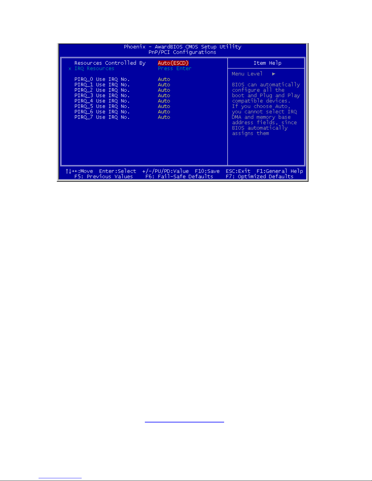
3.6 PnP/PCI Configurations
Resources Controlled By
This item configures all of the boot and Plug-and-Play compatible devices.
[Auto(ESCD)]: The system will automatically detect the settings.
[Manual]: Choose the specific IRQ resources in the “IRQ Resources” menu.
Page 43
http://www.TYAN.com
43
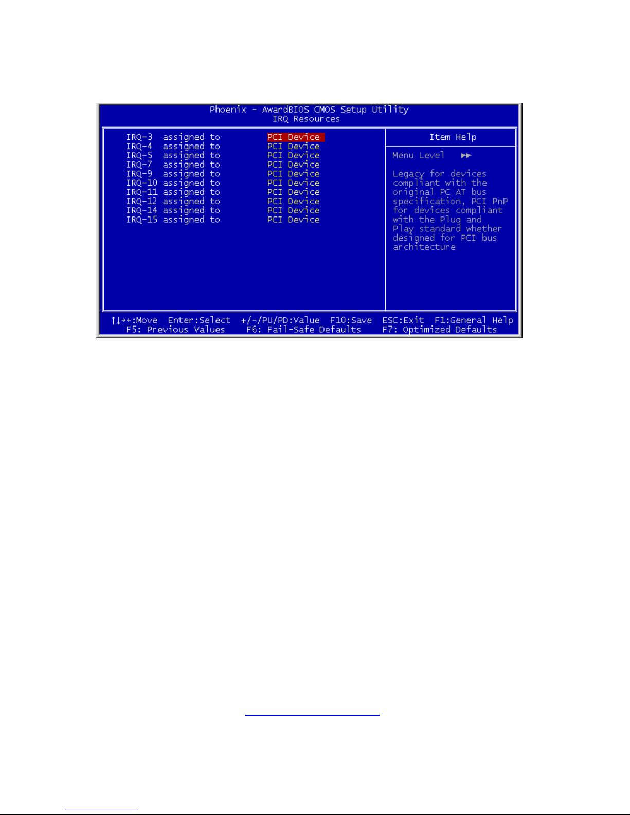
IRQ Resources:
Click <Enter> key to enter its submenu:
This item sets each system interrupt to either [PCI Device] or [Reserved].
PIRQ_0 Use IRQ No. ~PIRQ_7 Use IRQ No.
This item specifies the IRQ number manually or automatically for the devices
installed on PCI slots.
Page 44
http://www.TYAN.com
44
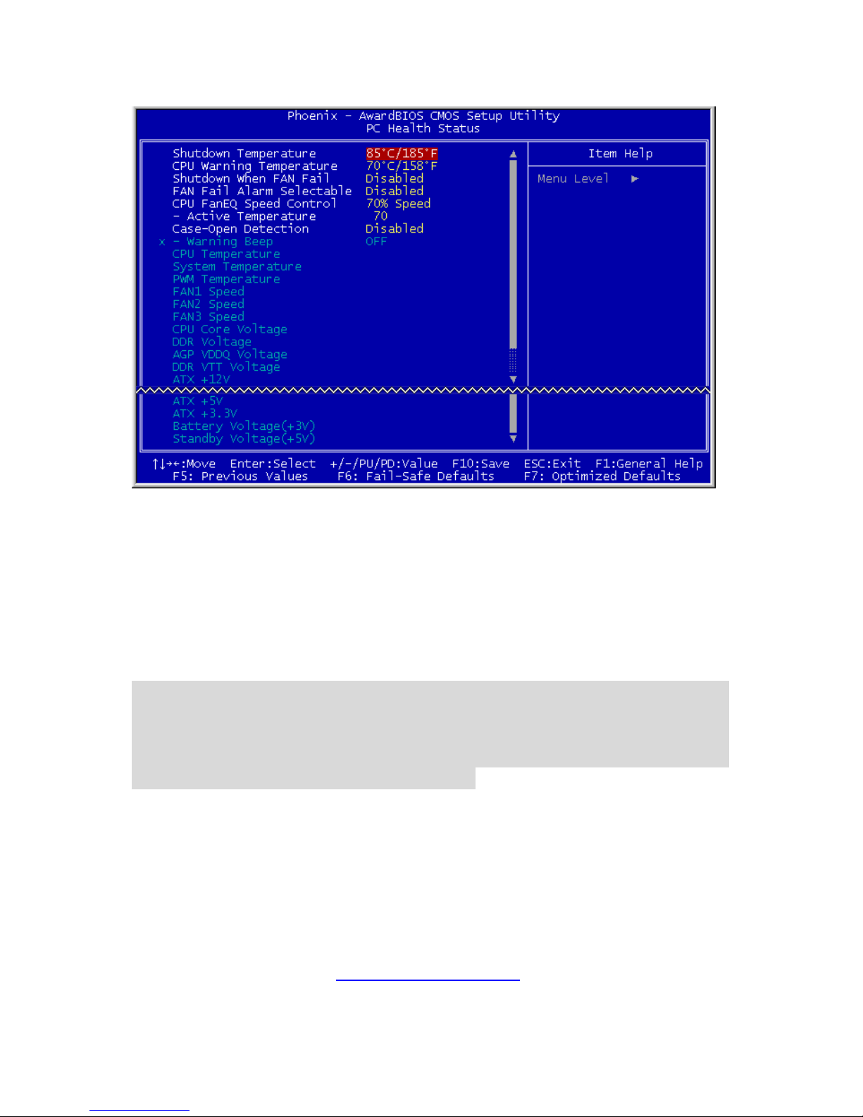
3.7 PC Health Menu
Shutdown Temperature
This item sets the temperature that would shutdown the system automatically in
order to prevent system overheats.
CPU Warning Temperature
This item selects the CPU’s warning temperature limit. Once the system has
detected that the CPU’s temperature exceeded the limit, warning beeps will
sound.
NOTE: The onboard hardware monitor function is capable of detecting these
system health conditions. If you want a warning message to pop-up or a
warning alarm to sound when an abnormal condition occurs, you must install
the “Hardware Doctor” utility. This utility is included in the “Driver & Utility
CD” that came packed with this motherboard.
Shutdown When Fan Fail
When set to [Enabled], the system will be shut down if the fan is not running.
FAN Fail Alarm Selectable
This item selects the fan that will be monitored for malfunction.
Page 45

http://www.TYAN.com
45
CPU FanEQ Speed Control
This item allows you to control the CPU fan speed down to a specific
percentage.
When set to a specific percentage, the CPU fan speed will run at the
percentage you set in this item if the temperature limit set in the item “Active
Temperature” is not exceeded.
The CPU fan speed will run at 100% regardless of what the percentag e you set
in this item if the temperature limit set in the item “Active Temperature” is
exceeded.
Active Temperature
This item sets the temperature limit that would activate the function of “CPU
FanEQ Speed Control” option.
Case-Open Detection
This option controls the function for case-opening detection device connected at
pin-7 and pin-8 at FPIO1 header.
[Disabled]: Disable the Case-Open Detection.
[Enabled]: Enable the Case-Open Detection.
[Cleared]: Clear the warning message when the case-opening situatio n is
detected.
Warning Beep
This option controls the onboard buzzer to beep when the case-opening
situation is detected.
All Voltages, Fans Speed and Thermal Monitoring
These unchangeable items list the current status of the CPU and environm ent
temperatures, fan speeds, and system power voltage.
NOTE: The hardware monitoring features for temperatures, fans and voltages
will occupy the I/O address from 294H to 297H. If you have a network adapter,
sound card or other add-on cards that might use those I/O addresses, please
adjust your add-on card I/O address to avoid using these addresses.
Page 46

http://www.TYAN.com
46
3.8 Load Fail-Safe Defaults
This option loads the BIOS default values for the most stable, minimalperformance system operations.
3.9 Load Optimized Defaults
This option loads the BIOS default values that are factory settings for optimalperformance system operations.
3.10 Set Password
This option protects the BIOS configuration or restricts access to the computer
itself.
3.11 Save & Exit Setup
This option saves your selections and exits the setup menu.
3.12 Exit Without Saving
This option exits the setup menu without saving any change.
Page 47

http://www.TYAN.com
47
Glossary
ACPI (Advanced Configuration and Power Interface): a power management
specification that allows the operating system to control the amount of power
distributed to the computer’s devices. Devices not in use can be turned off,
reducing unnecessary power expenditure.
AGP (Accelerated Graphics Port): a PCI-based interface which was designed
specifically for demands of 3D graphics applications. The 32-bit AGP channel
directly links the graphics controller to the main memory. While the channel runs
only at 66 MHz, it supports data transmission during both the rising and fall ing
ends of the clock cycle, yielding an effective speed of 133 MHz.
ATAPI (AT Attachment Packet Interface): also known as IDE or ATA; a drive
implementation that includes the disk controller on the device itself. It allows
CD-ROMs and tape drives to be configured as master or slave devices, just like
HDDs.
ATX: the form factor designed to replace the AT form factor. It improves on the
AT design by rotating the board 90 degrees, so that the IDE connectors are
closer to the drive bays, and the CPU is closer to the power supply and cooling
fan. The keyboard, mouse, USB, serial, and parallel ports are built-in.
Bandwidth: refers to carrying capacity. The greater the bandwidth, the more
data the bus, phone line, or other electrical path can carry. Greater bandwidth
results in greater speed.
BBS (BIOS Boot Specification): a feature within the BIOS that creates,
prioritizes, and maintains a list of all Initial Program Load (IPL) devices, and
then stores that list in NVRAM. IPL devices have the ability to load and execute
an OS, as well as provide the ability to return to the BIOS if the OS load process
fails. At that point, the next IPL device is called upon to attempt loading of the
OS.
BIOS (Basic Input/Output System): the program that resides in the ROM chip,
which provides the basic instructions for controlling your computer’s hardware.
Both the operating system and application software use BIOS routines to
ensure compatibility.
Buffer: a portion of RAM which is used to temporarily store data; usually from
an application though it is also used when printing and in m ost keyboard drivers.
The CPU can manipulate data in a buffer before copying it to a disk drive. While
Page 48

http://www.TYAN.com
48
this improves system performance (reading to or writing from a disk drive a
single time is much faster than doing so repeatedly) there is the possibility of
losing your data should the system crash. Information in a buffer is temporarily
stored, not permanently saved.
Bus: a data pathway. The term is used especially to refer to the connection
between the processor and system memory, and between the processor and
PCI or ISA local buses.
Bus mastering: allows peripheral devices and IDEs to access the s ystem
memory without going through the CPU (similar to DMA channels).
Cache: a temporary storage area for data that will be needed often by an
application. Using a cache lowers data access times since the information is
stored in SRAM instead of slower DRAM. Note that the cache is also much
smaller than your regular memory: a typical cache size is 51 2KB, while you may
have as much as 4GB of regular memory.
Closed and open jumpers: jumpers and jumper pins are active when they are
“on” or “closed”, and inactive when they are “off” or “open”.
CMOS (Complementary Metal-Oxide Semiconductors): chips that hold the
basic startup information for the BIOS.
COM port: another name for the serial port, which is called as such because it
transmits the eight bits of a byte of data along one wire, and receives data on
another single wire (that is, the data is transmitted in serial form, one bit after
another). Parallel ports transmit the bits of a byte on eight different wires at the
same time (that is, in parallel form, eight bits at the same time).
DDR (Double Data Rate): a technology designed to double the clock spee d of
the memory. It activates output on both the rising and falling edge of the system
clock rather than on just the rising edge, potentially doublin g output.
DIMM (Dual In-line Memory Module): faster and more capacious form of RAM
than SIMMs, and do not need to be installed in pairs.
DIMM bank: sometimes called DIMM socket because the physical slot and the
logical unit are the same. That is, one DIMM module fits into one DIMM socket,
which is capable of acting as a memory bank.
DMA (Direct Memory Access): channels that are similar to IRQs. DMA
channels allow hardware devices (like soundcards or keyboards) to access the
main memory without involving the CPU. This frees up CPU resources for other
Page 49

http://www.TYAN.com
49
tasks. As with IRQs, it is vital that you do not double up devices on a single line.
Plug-n-Play devices will take care of this for you.
DRAM (Dynamic RAM): widely available, very affordable form of RAM which
looses data if it is not recharged regularly (every few milliseconds). This refresh
requirement makes DRAM three to ten times slower than non-recharged RAM
such as SRAM.
ECC (Error Correction Code or Error Checking and Correcting) : allows data
to be checked for errors during run-time. Errors can subsequently be corrected
at the same time that they’re found.
EEPROM (Electrically Erasable Programmable ROM): also called Flash
BIOS, it is a ROM chip which can, unlike normal ROM, be updated. This allows
you to keep up with changes in the BIOS programs without having to buy a new
chip. TYAN’s BIOS updates can be found at http://www.tyan.com
ESCD (Extended System Configuration Data): a format for storing
information about Plug-n-Play devices in the system BIOS. This information
helps properly configure the system each time it boots.
Firmware: low-level software that controls the system hardware.
Form factor: an industry term for the size, shape, power supply type, and
external connector type of the Personal Computer Board (PCB) or motherboard.
The standard form factors are the AT and ATX.
Global timer: onboard hardware timer, such as the Real-Time Clock (RTC).
HDD: stands for Hard Disk Drive, a type of fixed drive.
H-SYNC: controls the horizontal synchronization/properties of the monitor.
HyperTransport
TM
: a high speed, low latency, scalable point-to-point link for
interconnecting ICs on boards. It can be significantly faster than a PCI bus for
an equivalent number of pins. It provides the bandwidth and flexibility critical for
today's networking and computing platforms while retaining the fundamental
programming model of PCI.
IC (Integrated Circuit): the formal name for the computer chip.
IDE (Integrated Device/Drive Electronics): a simple, self-contained HDD
interface. It can handle drives up to 8.4 GB in size. Almost all IDEs sold now are
in fact Enhanced IDEs (EIDEs), with maximum capacity determined by the
hardware controller.
Page 50

http://www.TYAN.com
50
IDE INT (IDE Interrupt): a hardware interrupt signal that goes to the IDE.
I/O (Input/Output): the connection between your computer and another piece
of hardware (mouse, keyboard, etc.)
IRQ (Interrupt Request): an electronic request that runs from a hardware
device to the CPU. The interrupt controller assigns priorities to incoming
requests and delivers them to the CPU. It is important that there is only one
device hooked up to each IRQ line; doubling up devices o n IRQ lines can lock
up your system. Plug-n-Play operating systems can take care of these det ails
for you.
Latency: the amount of time that one part of a system spends waiting for
another part to catch up. This occurs most commonly when the system sends
data out to a peripheral device and has to wait for the peripheral to spread
(peripherals tend to be slower than onboard system components).
NVRAM: ROM and EEPROM are both examples of Non-Volatile RAM, memory
that holds its data without power. DRAM, in contrast, is volatile.
Parallel port: transmits the bits of a byte on eight different wires at the same
time.
PCI (Peripheral Component Interconnect): a 32 or 64-bit local bus (data
pathway) which is faster than the ISA bus. Local buses are those which operate
within a single system (as opposed to a network bus, which connects multiple
systems).
PCI PIO (PCI Programmable Input/Output) modes: the data transfer modes
used by IDE drives. These modes use the CPU for data transfer (in contrast,
DMA channels do not). PCI refers to the type of bus used by these modes to
communicate with the CPU.
PCI-to-PCI bridge: allows you to connect multiple PCI devices onto one PCI
slot.
Pipeline burst SRAM: a fast secondary cache. It is used as a secondary cache
because SRAM is slower than SDRAM, but usually larger. Data is cached first
to the faster primary cache, and then, when the primary cache is full, to the
slower secondary cache.
PnP (Plug-n-Play): a design standard that has become ascendant in the
industry. Plug-n-Play devices require little set-up to use. Devices an d operating
systems that are not Plug-n-Play require you to reconfigure your s ystem each
time you add or change any part of your hardware.
Page 51

http://www.TYAN.com
51
PXE (Preboot Execution Environment): one of four components that together
make up the Wired for Management 2.0 baseline specification. PXE was
designed to define a standard set of preboot protocol services within a client
with the goal of allowing networked-based booting to boot using industry
standard protocols.
RAID (Redundant Array of Independent Disks): a way for the same data to
be stored in different places on many hard drives. By using t his metho d, the
data is stored redundantly and multiple hard drives will appear as a single drive
to the operating system. RAID level 0 is known as striping, where data is striped
(or overlapped) across multiple hard drives, but offers no fault-tolerance. RAID
level 1 is known as mirroring, which stores the data within at least two hard
drives, but does not stripe. RAID level 1 also allows for faster access time and
fault-tolerance, since either hard drive can be read at the same time. RAID level
0+1 is both striping and mirroring, providing fault-tolerance, striping, and faster
access all at the same time.
RAIDIOS: RAID I/O Steering (Intel)
RAM (Random Access Memory): technically refers to a type of memory where
any byte can be accessed without touching the adjacent da ta and is often
referred to the system’s main memory. This memory is available to any program
running on the computer.
ROM (Read-Only Memory): a storage chip which contains the BIOS; the basic
instructions required to boot the computer and start up the operating system.
SDRAM (Synchronous Dynamic RAM): called as such because it can keep
two sets of memory addresses open simultaneously. By transferring data
alternately from one set of addresses and then the other, SDRAM cuts down on
the delays associated with non-synchronous RAM, which must close one
address bank before opening the next.
Serial port: called as such because it transmits the eight bits of a byte of data
along one wire, and receives data on another single wire (that is, the data is
transmitted in serial form, one bit after another).
SCSI Interrupt Steering Logic (SISL): Architecture that allows a RAID
controller, such as AcceleRAID 150, 200 or 250, to implement RAID on a
system board-embedded SCSI bus or a set of SCSI busses. SISL: SCSI
Interrupt Steering Logic ( LSI ) (only on LSI SCSI boards)
Sleep/Suspend mode: in this mode, all devices except the CPU shut down.
Page 52

http://www.TYAN.com
52
SDRAM (Static RAM): unlike DRAM, this type of RAM does not need to be
refreshed in order to prevent data loss. Thus, it is faster and more expensive.
SLI (Scalable Link Interface): NVIDIA SLI technology links two graphics cards
together to provide scalability and increased performance. NVIDIA SLI takes
advantage of the increased bandwidth of the PCI Express bus architecture, and
features hardware and software innovations within NVIDIA GPUs (graphics
processing units) and NVIDIA MCPs (media and communications processors).
Depending on the application, NVIDIA SLI can deliver as much as two times the
performance of a single GPU configuration.
Standby mode: in this mode, the video and hard drives shut down; all other
devices continue to operate normally.
UltraDMA-33/66/100: a fast version of the old DMA channel. UltraDMA i s also
called UltraATA. Without a proper UltraDMA controller, your system cannot take
advantage of higher data transfer rates of the new UltraDMA/UltraATA hard
drives.
USB (Universal Serial Bus): a versatile port. This one port type can function
as a serial, parallel, mouse, keyboard or joystick port. It is fast enough to
support video transfer, and is capable of supporting up to 127 dais y-chained
peripheral devices.
VGA (Video Graphics Array): the PC video display standard
V-SYNC: controls the vertical scanning properties of the monitor.
ZCR (Zero Channel RAID): PCI card that allows a RAID card to use the
onboard SCSI chip, thus lowering cost of RAID solution
ZIF Socket (Zero Insertion Force socket): these sockets make it possible to
insert CPUs without damaging the sensitive CPU pins. The CPU is lightl y
placed in an open ZIF socket, and a lever is pulled down. This shifts the
processor over and down, guiding it into the board and locking it into place.
Page 53

http://www.TYAN.com
53
Technical Support
If a problem arises with your system, you should turn to your deal er for help first.
Your system has most likely been configured by them, and they should have the
best idea of what hardware and software your system contains. Furthermore, if
you purchased your system from a dealer near you, you can brin g your system
to them to have it serviced instead of attempting to do so yourself (which can
have expensive consequences).
Help Resources:
1. See the beep codes section of this manual.
2. See the TYAN website for FAQ’s, bulletins, driver updates,
and other information: http://www.tyan.com
3. Contact your dealer for help BEFORE calling TYAN.
4. Check the TYAN user group:
alt.comp.periphs.mainboard.TYAN
Returning Merchandise for Service
During the warranty period, contact your distributor or system vendor FIRST for
any product problems. This warranty only covers normal customer use and
does not cover damages incurred during shippi ng or failure due to the alteration,
misuse, abuse, or improper maintenance of products.
NOTE: A receipt or copy of your invoice marked with th e date of purchase
is required before any warranty service can be rendered. You may obtain
service by calling the manufacturer for a Return Merchandise
Authorization (RMA) number. The RMA number should be prominently
displayed on the outside of the shipping carton and the package should
be mailed prepaid. TYAN will pay to have the board shipped back to you.
Page 54
http://www.TYAN.com
54
Notice for the USA
Compliance Information Statement (Declaration of
Conformity Procedure) DoC
FCC Part 15: This device complies with part 15 of the FCC
Rules
Operation is subject to the following conditions:
This device may not cause harmful interference, and
This device must accept any interference received including interference th at
may cause undesired operation. If this equipment does cause harmful
interference to radio or television reception, which can be determined b y tur ning
the equipment off and on, the user is encouraged to try one or more of the
following measures:
Reorient or relocate the receiving antenna.
Increase the separation between the equipment and the receiver.
Plug the equipment into an outlet on a circuit different from that of the receiver.
Consult the dealer on an experienced radio/television technicia n for help.
Notice for Canada
This apparatus complies with the Class B limits for radio interference as
specified in the Canadian Department of Communications Radio Interference
Regulations. (Cet appareil est conforme aux norms de Classe B d’interference
radio tel que specifie par le Ministere Canadien des Communications dans les
reglements d’ineteference radio.)
Notice for Europe (CE Mark)
This product is in conformity with the Council Directive
89/336/EEC, 92/31/EEC (EMC).
CAUTION: Lithium battery included with this board. Do not puncture, mutilate,
or dispose of battery in fire. Danger of explosion if battery is incorrectly replaced.
Replace only with the same or equivalent type recommended by manufact urer.
Dispose of used battery according to manufacturer instructions and in
accordance with your local regulations.
Document #: D1695-100
 Loading...