

TYAN S5547 User Manual

http://www.tyan.com
1
S5547
Version 1.0
Copyright
Copyright © 2016 MiTAC International Corporation. All rights reserved. No part of
this manual may be reproduced or translated without prior written consent from
MiTAC International Corporation.
Trademark
All registered and unregistered trademarks and company names contained in this
manual are property of their respective owners including, but not limited to the
following.
TYAN® is a trademark of MiTAC International Corporation.
Intel® is a trademark of Intel® Corporation.
AMI, AMI BIOS are trademarks of AMI Technologies.
Microsoft®, Windows® are trademarks of Microsoft Corporation.
Winbond® is a trademark of Winbond Electronics Corporation.
Notice
Information contained in this document is furnished by MiTAC International
Corporation and has been reviewed for accuracy and reliability prior to printing.
MiTAC assumes no liability whatsoever, and disclaims any express or implied
warranty, relating to sale and/or use of TYAN® products including liability or
warranties relating to fitness for a particular purpose or merchantability. MiTAC
retains the right to make changes to product descriptions and/or specifications at
any time, without notice. In no event will MiTAC be held liable for any direct or
indirect, incidental or consequential damage, loss of use, loss of data or other
malady resulting from errors or inaccuracies of information contained in this
document.

http://www.tyan.com
2
Contents
S5547 ............................................................................................................ 1
Before you begin… .................................................................................... 3
Chapter 1: Instruction ................................................................................ 4
1.1 Congratulations ................................................................................. 4
1.2 Hardware Specifications .................................................................... 4
Chapter 2: Board Installation ..................................................................... 6
2.1 Board Image ...................................................................................... 7
2.2 Block Diagram ................................................................................... 8
2.3 Motherboard Mechanical Drawing ..................................................... 9
2.4 Board Parts, Jumpers and Connectors ........................................... 10
2.5 Installing the Processor and Heatsink ............................................. 16
2.6 Tips on Installing Motherboard in Chassis ...................................... 20
2.7 Installing the Memory ...................................................................... 22
2.8 Attaching Drive Cables .................................................................... 25
2.9 Installing Add-In Cards .................................................................... 26
2.10 Connecting External Devices ........................................................ 27
2.11 Installing the Power Supply ........................................................... 28
2.12 Finishing Up ................................................................................... 28
Chapter 3: BIOS Setup ............................................................................. 29
3.1 About the BIOS ................................................................................ 29
3.2 Main Menu ....................................................................................... 31
3.3 Advanced Menu ............................................................................... 32
3.4 Chipset Menu .................................................................................. 62
3.5 Security ............................................................................................ 68
3.6 Boot ................................................................................................. 73
3.7 Save & Exit ...................................................................................... 76
Chapter 4: Diagnostics ............................................................................. 78
4.1 Flash Utility ...................................................................................... 78
4.2 AMIBIOS Post Code (Aptio) ............................................................ 79
Appendix I: Fan and Temp Sensors ....................................................... 86
Glossary ..................................................................................................... 89
Technical Support .................................................................................... 95
http://www.tyan.com
3
Before you begin…
Check the box contents!
The retail motherboard package should contain the following:
1 x S5547 Motherboard
1 x Rear IO shielding
1 x S5547 Quick Installation Guide
1 x TYAN® Driver CD
2 x SATA Single Cable
IMPORTANT NOTE:
Sales sample may not come with the accessory listed above.
Please contact your sales representative to help order accessory for your
evaluation.

http://www.tyan.com
4
Chapter 1: Instruction
1.1 Congratulations
You have purchased the powerful TYAN® S5547 motherboard, based on the Intel®
Skylake PCH (H110) chipset. The S5547 is designed to support single Intel®
Core™ i3/i5/i7 series processor, and up to 32GB of un-buffered ECC UDIMM
DDR4 2133MHz / DDR4 memory. Leveraging advanced technology from Intel®, the
S5547 is capable of offering scalable 32 and 64-bit computing, high-bandwidth
memory design, and lightning-fast PCI-E bus implementation.
The S5547 not only empowers you in today‟s demanding IT environment but also
offers a smooth path for future application upgradeability. All of these rich feature
sets provide the S5547 with the power and flexibility to meet demanding
requirements for today‟s IT environments.
Remember to visit the TYAN® website at http://www.tyan.com. There you can find
all the information on all TYAN® products as well as all the supporting documentation,
FAQs, Drivers and BIOS upgrades.
1.2 Hardware Specifications
TYAN S5547 (S5547G2NR)
Processor
Supported CPU
Series
Intel Core i3/ i5/ i7 series processors
Socket Type / Q'ty
LGA1151 / (1)
Thermal Design
Power (TDP)
wattage
65W
Chipset
PCH
Intel H110
Super I/O
NCT6683D-T
Memory
Supported DIMM
Qty
(2) DIMM slots
DIMM Type / Speed
Unbuffered ECC UDIMM DDR4 2133
Capacity
Up to 32GB
Memory channel
1 Channel
Memory voltage
1.2V
Expansion
Slots
PCI-E
(1) PCI-E Gen3 x16 slot / (1) PCI-E Gen3 x8 slot
LAN
Port Q'ty
(1) GbE, (1) PHY
Controller
Intel I210-AT
PHY
Intel I219-LM
http://www.tyan.com
5
Storage
SATA
Connector
(4) SATA
Controller
Intel H110
Speed
6.0 Gb/s
RAID
Non-support
Graphic
Connector type
(1) Display port
Chipset
Intel H110
Input /Output
USB
(5) USB2.0 ports (4 at rear, 1 Type-A)/ (4) USB3.0
ports (2 at rear, 2 via cable)
COM
(1) header
Display port
(1) Display Port
RJ-45
(2) GbE ports
Power
ATX 24-pin + 4-pin power connectors
Front Panel
(1) 2 x 5 header
SATA
(4) SATA-III connectors
System
Monitoring
Chipset
NCT6683D-T
Voltage
Monitors voltage for CPU, memory, chipset & power
supply
Fan
Total (4) 4-pin headers
Temperature
Monitors temperature for CPU & system environment
Others
Watchdog timer support
BIOS
Brand / ROM size
AMI / 16MB
Feature
Hardware Monitor / ACPI 5.0 / SMBIOS 3.0/PnP/Wake
on LAN / ACPI sleeping states S3,S4,S5 / Boot from
USB device ,PXE via LAN ,Storage / User
Configurable FAN PWM Duty Cycle / Console
Redirection
Physical
Dimension
Form Factor
Flex ATX
Board Dimension
9"x7.5" (228.6x190.5mm)
Operating
System
OS supported list
Please refer to our Intel OS supported list.
Regulation
FCC (DoC)
Class B
CE (DoC)
Yes
Operating
Environment
Operating Temp.
10° C ~ 35° C (50° F~ 95° F)
Non-operating
Temp.
- 40° C ~ 70° C (-40° F ~ 158° F)
In/Non-operating
Humidity
90%, non-condensing at 35° C
RoHS
RoHS 6/6 Compliant
Yes
Package
Contains
Motherboard
(1) S5547 Motherboard
Manual
(1) Web User's manual / (1) Quick Installation Guide
Installation CD
(1) TYAN installation CD
http://www.tyan.com
6
Chapter 2: Board Installation
You are now ready to install your motherboard.
How to install our products right… the first time
The first thing you should do is read this user‟s manual. It contains important
information that will make configuration and setup much easier. Here are some
precautions you should take when installing your motherboard:
(1) Ground yourself properly before removing your motherboard from the
antistatic bag. Unplug the power from your computer power supply and
then touch a safely grounded object to release static charge (i.e. power
supply case). For the safest conditions, MiTAC recommends wearing a
static safety wrist strap.
(2) Hold the motherboard by its edges and do not touch the bottom of the
board, or flex the board in any way.
(3) Avoid touching the motherboard components, IC chips, connectors,
memory modules, and leads.
(4) Place the motherboard on a grounded antistatic surface or on the antistatic
bag that the board was shipped in.
(5) Inspect the board for damage.
The following pages include details on how to install your motherboard into your
chassis, as well as installing the processor, memory, disk drives and cables.
Caution!
1. To avoid damaging the motherboard and associated
components, do not use torque force greater than
7kgf/cm (6.09 lb/in) on each mounting screw for
motherboard installation.
2. Do not apply power to the board if it has been
damaged.
http://www.tyan.com
7
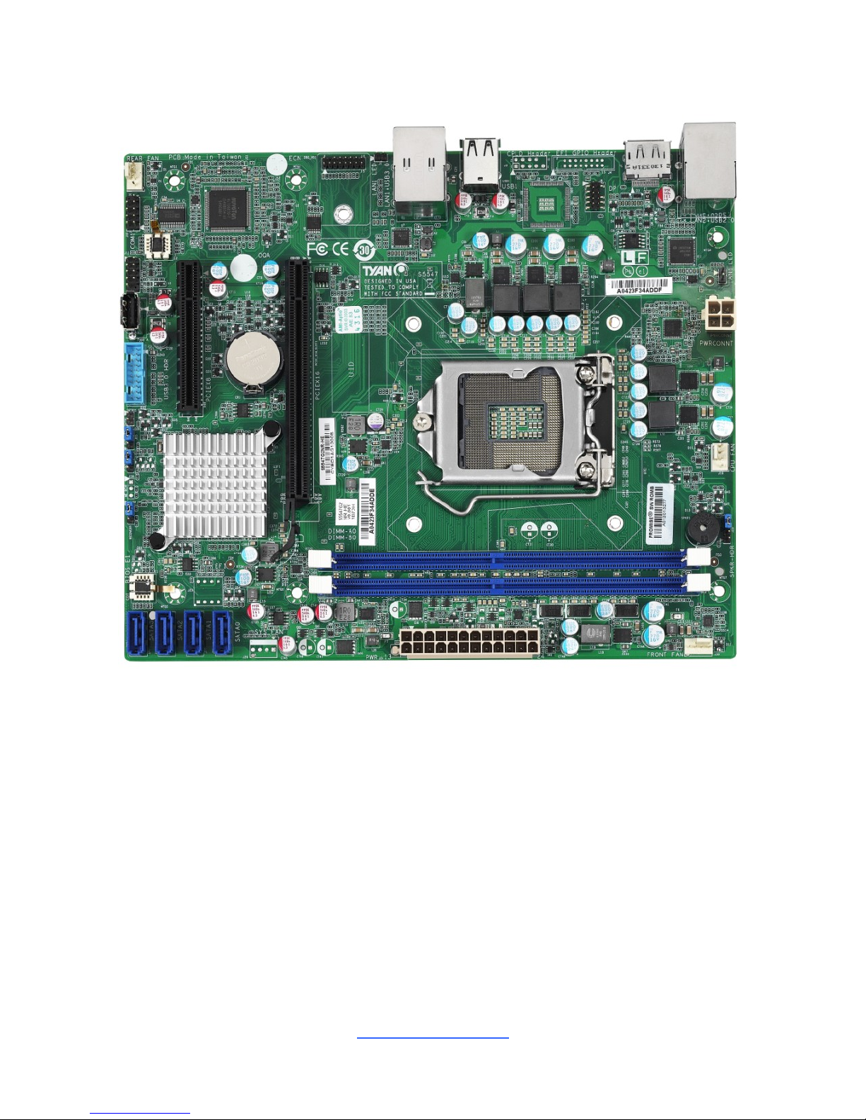
2.1 Board Image
S5547G2NR
This picture is representative of the latest board revision available at the time of
publishing. The board you receive may not look exactly like the above picture.
http://www.tyan.com
8
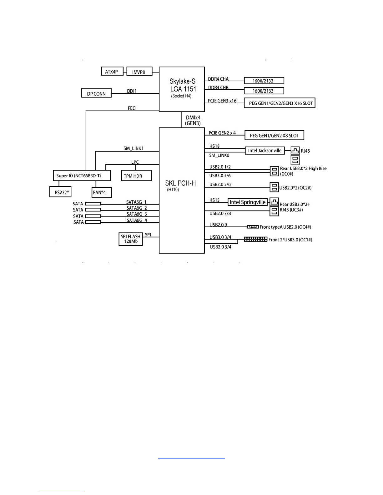
2.2 Block Diagram
S5547 Block Diagram
http://www.tyan.com
9
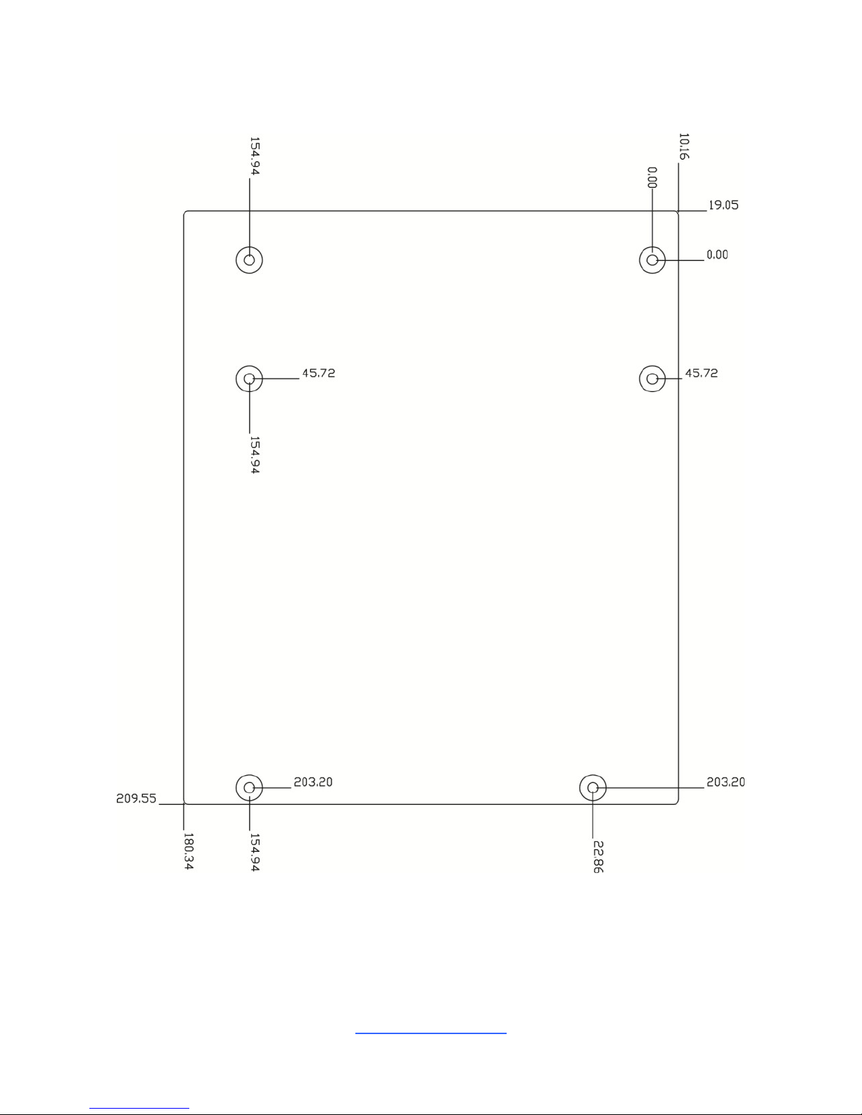
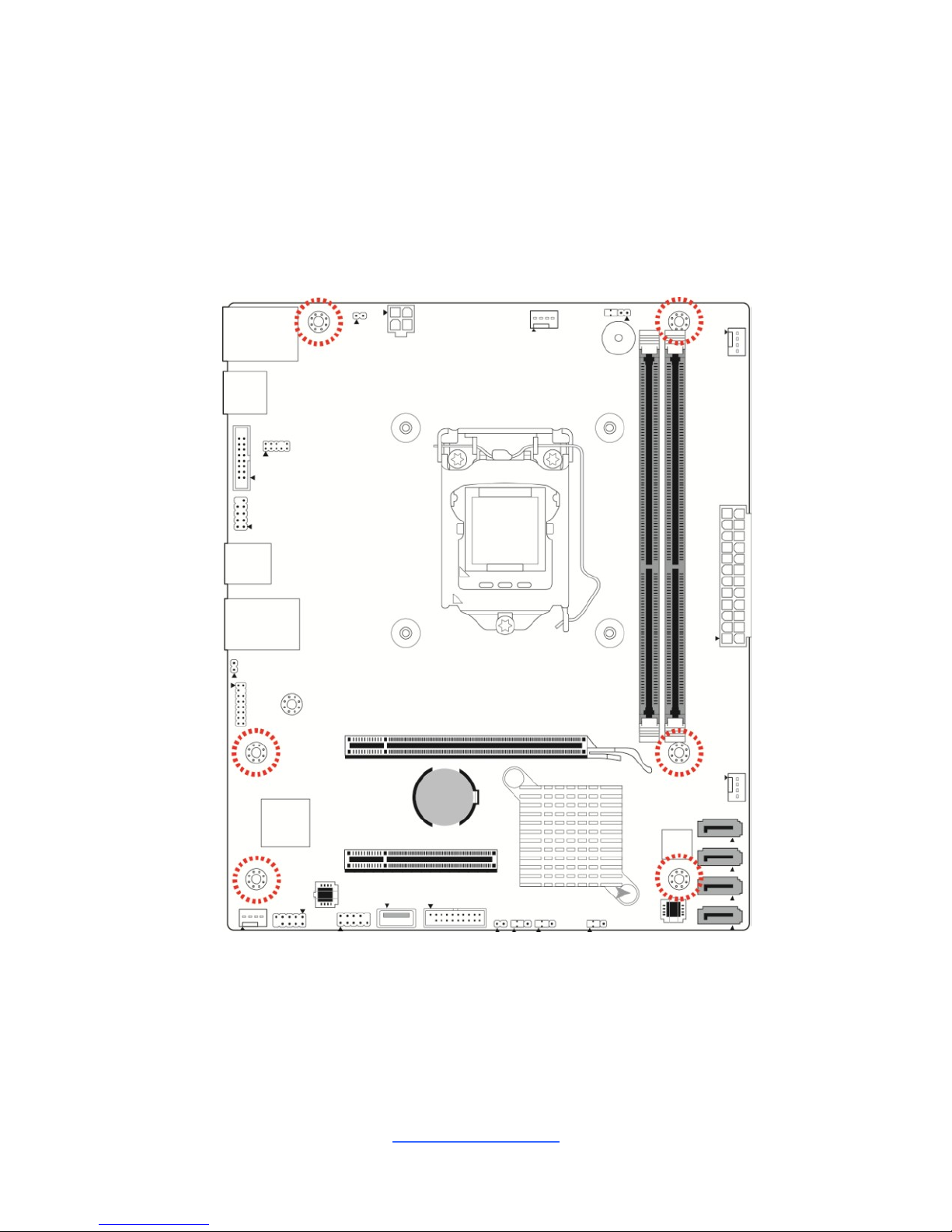
2.3 Motherboard Mechanical Drawing
http://www.tyan.com
10
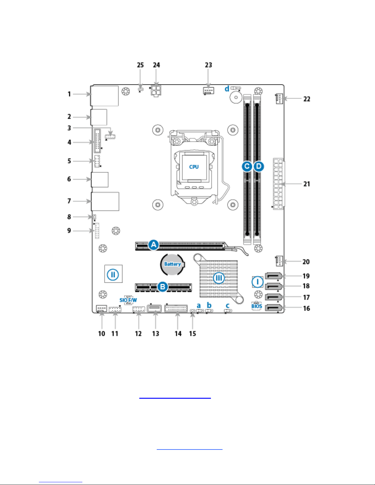
2.4 Board Parts, Jumpers and Connectors
This diagram is representative of the latest board revision available at the time of
publishing. The board you receive may not look exactly like the above diagram. The
DIMM slot numbers shown above can be used as a reference when reviewing the
DIMM population guidelines shown later in the manual. For the latest board revision,
please visit our web site at http://www.tyan.com.
http://www.tyan.com
11
Motherboard Components
Connectors
1. RJ45 LAN Port #1 (LAN1) + Dual USB2.0
ports (J6)
14. USB 3.0 HDR (J14)
2. Display Port (J7)
15. INTRUDER HDR (INTRD1)
3. LPC Header (J8)
16. 7pin SATA 3.0 Connector (SATA 3) (J25)
4. Port 80 Header for CPLD (J4) for EFI
17. 7pin SATA 3.0 Connector (SATA 2) (J26)
5. JTAG Header for CPLD (J3) for EFI
18. 7pin SATA 3.0 Connector (SATA 1) (J27)
6 Dual USB 2.0 Ports (USB1)
19. 7pin SATA 3.0 Connector (SATA 0) (J28)
7. RJ45 LAN Port #2 (LAN2) + Dual USB3.0
ports (J5)
20. SYS FAN (J29)
8. LAN2 LED HDR (J1)
21. 24 pin power connector (J24)
9. Port80 Debug Header and TPM HDR
(DBG_HD1)
22. Front FAN (J30)
10. Rear FAN (J2)
23. CPU FAN (J16)
11. COM port HDR (J10)
24. 4-Pin ATX Power Connector (PWRCONN1)
12. Front Panel HDR (J11)
25. LAN1 LED HDR (J12)
13. USB2.0 TYPE A Connector (J13)
Sockets/Chipset/Buttons
CPU Socket (U7E1)
iii Intel H110 (SKL PCH) (U3F1)
BIOS Socket (E1)
ii Nuvoton NCT6683D-T SIO (U3)
SIO F/W Socket (E2)
i SMB Bus Socket for CPLD (J23) for EFI
Jumpers
a ME DISABLE Jumper (J15)
c Recovery Jumper (J19)
b Clear CMOS Jumper (J17)
d Buzzer Jumper (J20)
Slots
A PCIE X16 slot (PCIE_X16_SLOT1)
B PCIE X8 slot (PCIE_X8_SLOT1, signal up to X4)
C DIMM_A0 (J8C1)
D DIMM_B0 (J8C2)
http://www.tyan.com
12
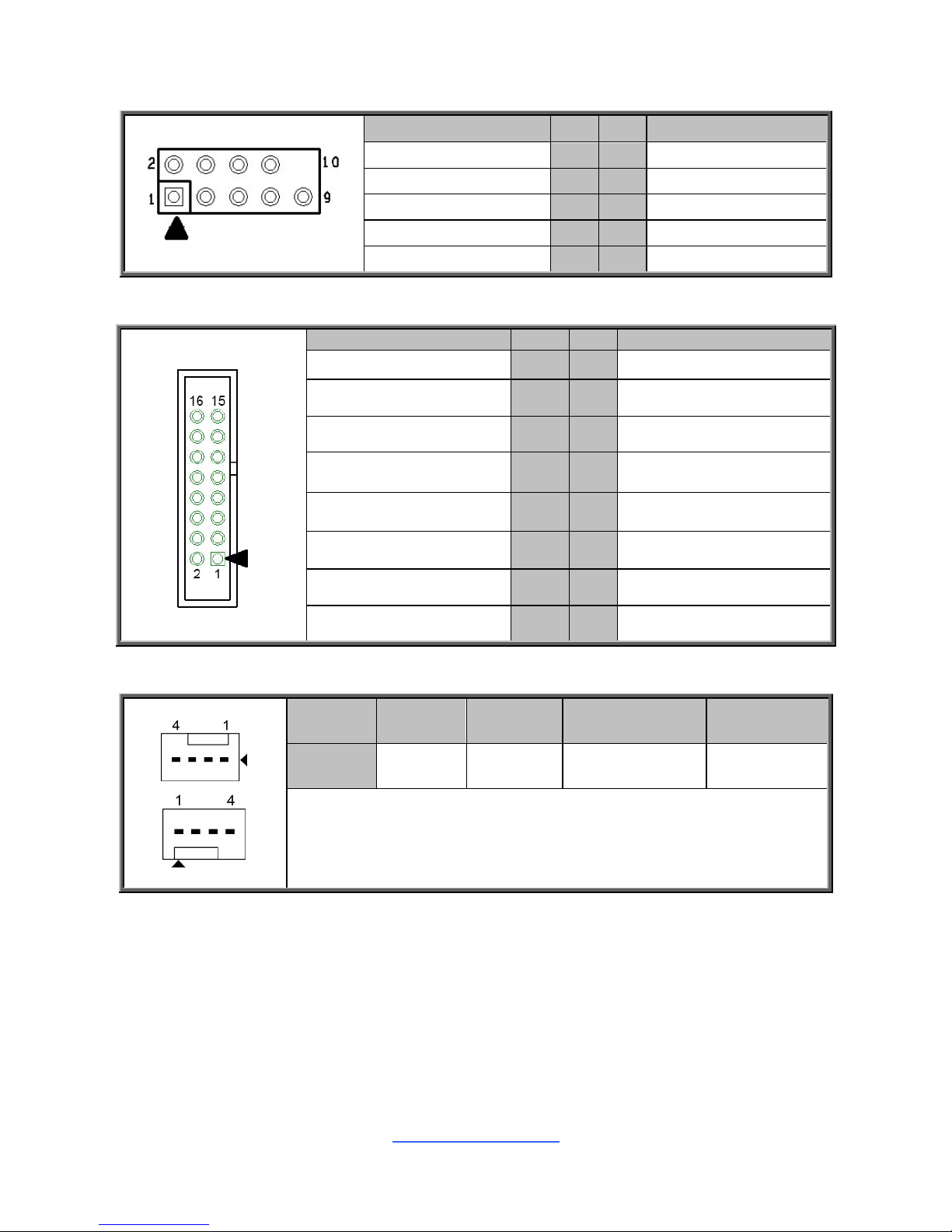
J3: JTAG Header for CPLD (for EFI)
Signal
Pin
Pin
Signal
CPLD_JTAG_TCK
1
2
GND
CPLD_JTAG_TDO
3
4
+3.3V
CPLD_JTAG_TMS
5
6
NC
NC
7
8
GND
CPLD_JTAG_TDI
9
10
KEY
J4: Port 80 Header for CPLD (for EFI)
Signal
Pin
Pin
Signal
CPLD_SMBCLK
1
2
+3.3V
CPLD_SMBDATA
3
4
CPLD_7SEG_LEDA
CPLD_7SEG_DGH_LR
5
6
+3.3V
GND
7
8
CPLD_7SEG_LEDB
CPLD_7SEG_DGL_LR
9
10
CPLD_7SEG_LEDC
SIOGP75
11
12
CPLD_7SEG_LEDD
SIOGP76
13
14
CPLD_7SEG_LEDE
CPLD_7SEG_LEDG
15
16
CPLD_7SEG_LEDF
J16 (CPU FAN) / J30 (Front FAN) / J2 (Rear FAN): 4-pin FAN Connector
Pin 1 2 3 4
Signal
GND
VCC12
TACHOMETER
PWM
Use this header to connect the cooling fan to your motherboard to
keep the system stable and reliable.
Note: A 4-pin fan is required for fan support 4pin Control
http://www.tyan.com
13
J29 (SYS FAN): 4-pin FAN Connector
Pin 1 2 3 4
Signal
GND
VCC12
TACHOMETER
VCC5
Use this header to connect the cooling fan to your motherboard to
keep the system stable and reliable.
Note: A 4-pin fan without FAN speed Control
J11: Front Panel Header
Signal
Pin
Pin
Signal
VCC5
1
2
GRN BLNK HRD
SATA LED
3
4
YLW BLNK HRD
GND
5
6
PWRBTN
FP RST
7
8
GND
VCC
9
10
KEY
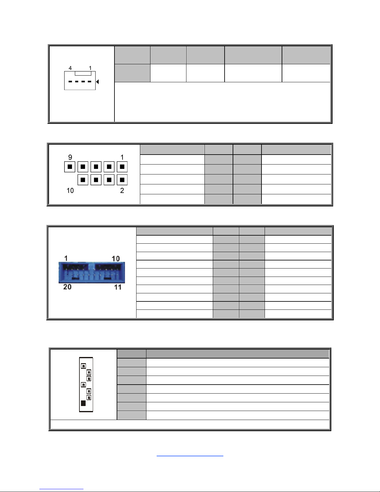
J14: Front USB3.0 Header
Signal
Pin
Pin
Signal
5V_AUX
1
2
USB3_RX_N
USB3_RX_P
3
4
GND
USB3_TX_N
5
6
USB3_TX_P
GND
7
8
USB_DN
USB_DP
9
10
USB_OC#
USB_DP
11
12
USB_DN
GND
13
14
USB3_TX_P
USB3_TX_N
15
16
GND
USB3_RX_P
17
18
USB3_RX_N
5V_AUX
19
20
Key
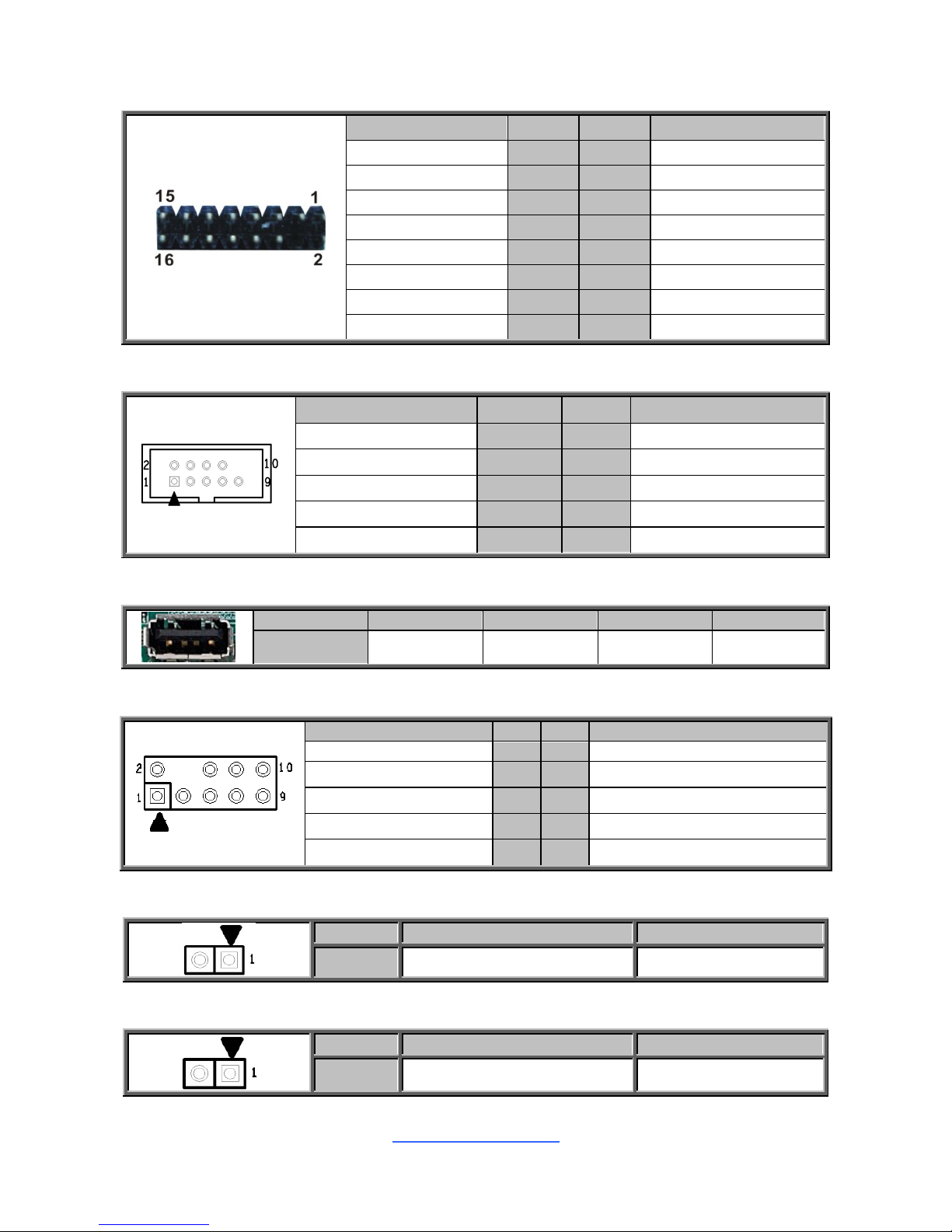
SATA0(J28)/SATA1(J27)/SATA2(J26)/SATA3(J25) : 7-pin vertical SATA3.0
Connector(Blue)
7
1
Name
TYPE
S1
GND
S2
SATA TX DP
S3
SATA TX DN
S4
GND
S5
SATA RX DN
S6
SATA RX DP
S7
GND
Connects to the Serial ATA ready drives via the Serial ATA cable.
http://www.tyan.com
14
DBG_HD1: TYAN Module Header (Port80 Debug Header)
Signal
Pin
Pin
Signal
P3V3
1
2
FRAME_N
LAD0
3
4
KEY
LAD1
5
6
PLT_RST_N
LAD2
7
8
GND
LAD3
9
10
CLK_24M
DBG_SERIRQ
11
12
GND
DBG_PRES_N
13
14
VCC3_AUX
TPM_ADDR_MB
15
16
PCH_TPM_PP_EN
J10: COM Header
Signal
Pin
Pin
Signal
DCD
1
2
DSR
SIN
3
4
RTS
SOUT
5
6
CTS
DTR
7
8
RI
GND
9
10
KEY
J13: Vertical (Type A) USB2.0 Connectors
Pin 1 2 3 4
Signal
5V_AUX
USB_DN
USB_DP
GND
J8: LPC Header
Signal
Pin
Pin
Signal
+3.3V
1
2
LPC_LFRAME_N_ESPI_CS0
LPC_LAD0_ESPI_IO0
3
4
KEY-Pin
LPC_LAD0_ESPI_IO1
5
6
NIC_RESET#
LPC_LAD0_ESPI_IO2
7
8
GND
LPC_LAD0_ESPI_IO3
9
10
CLK_24M
J1: LAN2 LED Header
Pin
1
2
Signal
LAN1_LED1_FP+
LAN1_LINK_ACT#
J12: LAN1 LED Header
Pin
1
2
Signal
LAN2_LED1_FP+
LAN2_LINK_ACT#
http://www.tyan.com
15
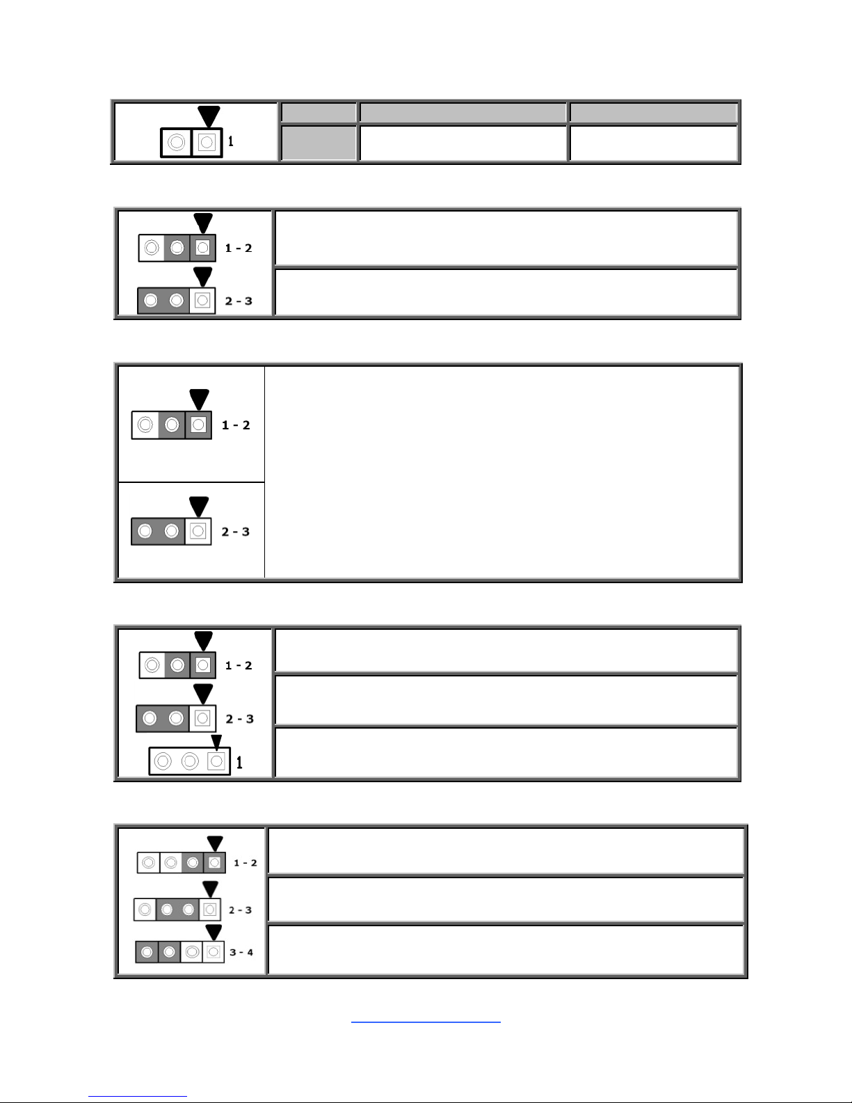
INTRD1: Intruder Header
Pin
1
2
Signal
GND
INTRUDER
J15: ME DISABLE Jumper
Pin 1-2 Closed: Normal Mode (Default)
Pin 2-3 Closed: ME Disable Mode
J17: Clear CMOS Jumper
Normal (Default)
You can reset the CMOS settings by using this jumper. This can be
useful if you have forgotten your system/setup password, or need to
clear the system BIOS setting.
1. Power off system and disconnect power connectors from the
motherboard.
2. Remove the jumper from Pin_2 and Pin_3 (Default setting).
3. Move the jumper cap to close Pin_1 and Pin_2 for several seconds
to Clear CMOS.
4. Put jumper cap back to Pin_2 and Pin_3 (Default setting).
5. Reconnect power connectors to the motherboard and power on
system.
Clear CMOS
J19: Recovery Jumper
Pin 1-2 Closed: Normal Mode (Default)
Pin 2-3 Closed: Configure
Remove Cap: Recovery
J20: BUZZER Jumper
Pin 3-4 Closed: Disable
Pin 2-3 Closed: Disable
Pin 3-4 Closed: Enable (Default)
http://www.tyan.com
16
2.5 Installing the Processor and Heatsink
The types of processors supported by the S5547 are listed in the 1.2 Hardware
Specifications section on page 4. Check our website at http://www.tyan.com for
the latest list of validated Intel® processors for this specific motherboard.
NOTE: MiTAC is not liable for damage as a result of operating an
unsupported configuration.
Processor Installation (SNB_H4 (LGA1151) for Intel Skylake CPU)
Follow the steps below to install the processors and heat sinks.
Please note that the illustrations are based on a SNB_H4 (LGA1151) which may not
look exactly like the motherboard you purchased. Therefore, the illustrations should
be held for your reference only.
NOTE: Please save and replace the CPU protection cap when returning for service.
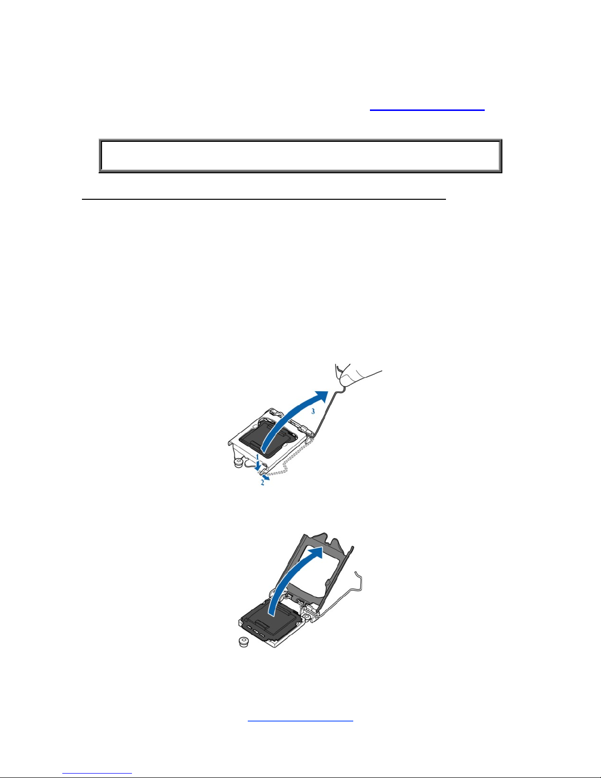
1. Locate the CPU socket.
2. Pull the CPU lever slightly away from the socket and then push it to a fully
open position.
3. Open the CPU socket cover.
http://www.tyan.com
17
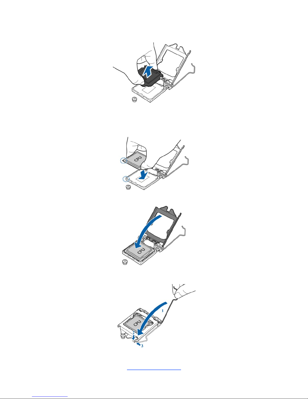
4. Remove the CPU protection cap.
5. Install the processor and make sure the gold arrow is located in the right
direction with two notches properly aligned.
6. Close the CPU socket cover.
7. Press the socket lever down to lock the CPU in place.
http://www.tyan.com
18
Heat sink Installation
After installing the processor, you should proceed to install the heat sink. The CPU
heat sink will ensure that the processor do not overheat and continue to operate at
maximum performance for as long as you own them. The overheated processor is
dangerous to the motherboard.
For the safest method of installation and information on choosing the appropriate
heat sink, using heat sinks validated by Intel®. Please refer to the Intel® website:
http://www.intel.com
The following diagram illustrates how to install the heat sink for the SNB_H4
(LGA1151) socket.
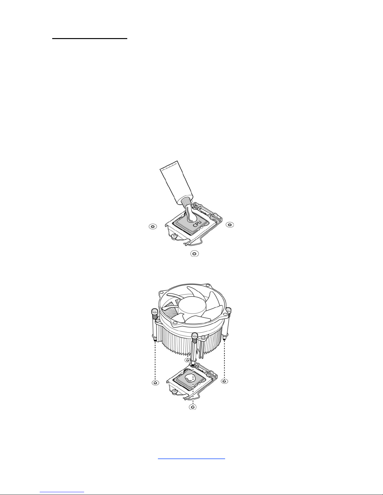
1. Apply the thermal grease.
2. Place the heat sink on top of the CPU and push the 4 latches in a diagonal
pattern to lock it in place.
http://www.tyan.com
19
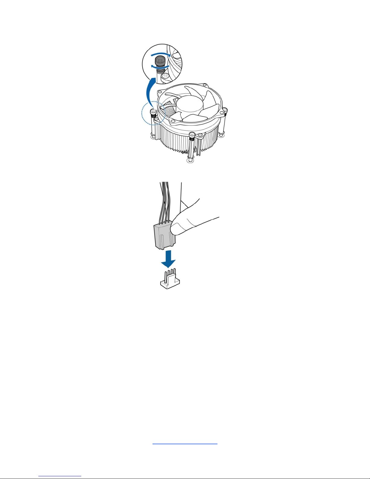
3. Secure the heat sink screws.
4. Connect the fan cable to complete the installation.
http://www.tyan.com
20
2.6 Tips on Installing Motherboard in Chassis
Before installing your motherboard, make sure your chassis has the necessary
motherboard support studs installed. These studs are usually metal and are gold in
color. Usually, the chassis manufacturer will pre-install the support studs. If you are
unsure of stud placement, simply lay the motherboard inside the chassis and align
the screw holes of the motherboard to the studs inside the case. If there are any
studs missing, you will know right away since the motherboard will not be able to be
securely installed.
Note: Be especially careful to look for extra stand-offs. If there are any stand-offs
present that are not aligned with a mounting hole on the motherboard, it will likely
short components on the back of the motherboard when installed. This will cause
malfunction and/or damage to your motherboard.
http://www.tyan.com
21
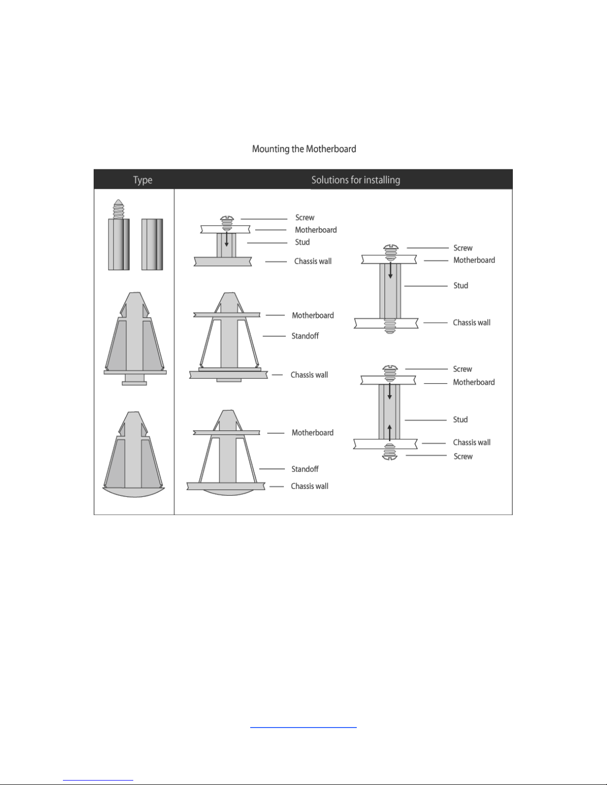
Some chassis include plastic studs instead of metal. Although the plastic studs are
usable, MiTAC recommends using metal studs with screws that will fasten the
motherboard more securely in place.
Below is a chart detailing what the most common motherboard studs look like and
how they should be installed.
http://www.tyan.com
22
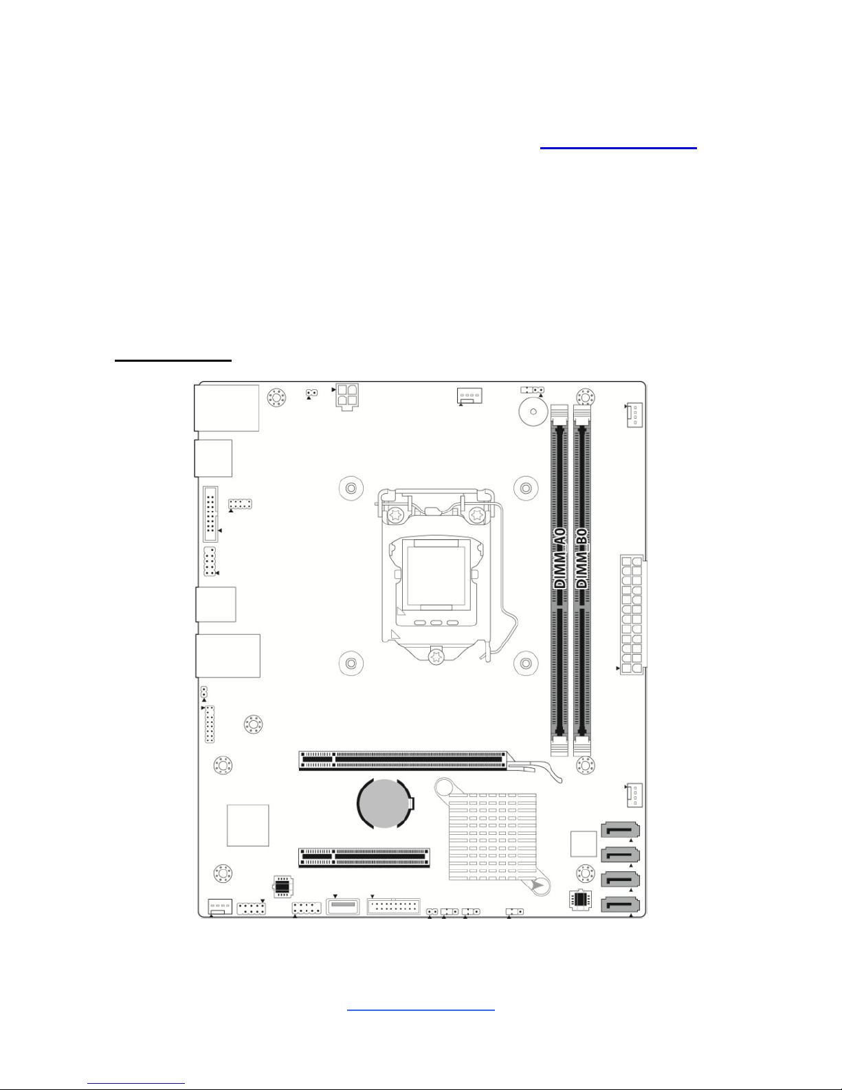
2.7 Installing the Memory
Before installing memory, ensure that the memory you have is compatible with the
motherboard and processor. Check the TYAN Web site at http://www.tyan.com for
details of the type of memory recommended for your motherboard.
Supports up to 32GB of un-buffered ECC UDIMM DDR4 2133MHz memory
Supports single/dual rank memory
All installed memory will automatically be detected and no jumpers or settings
need changing
All memory must be of the same type and density
DIMM Location
http://www.tyan.com
23
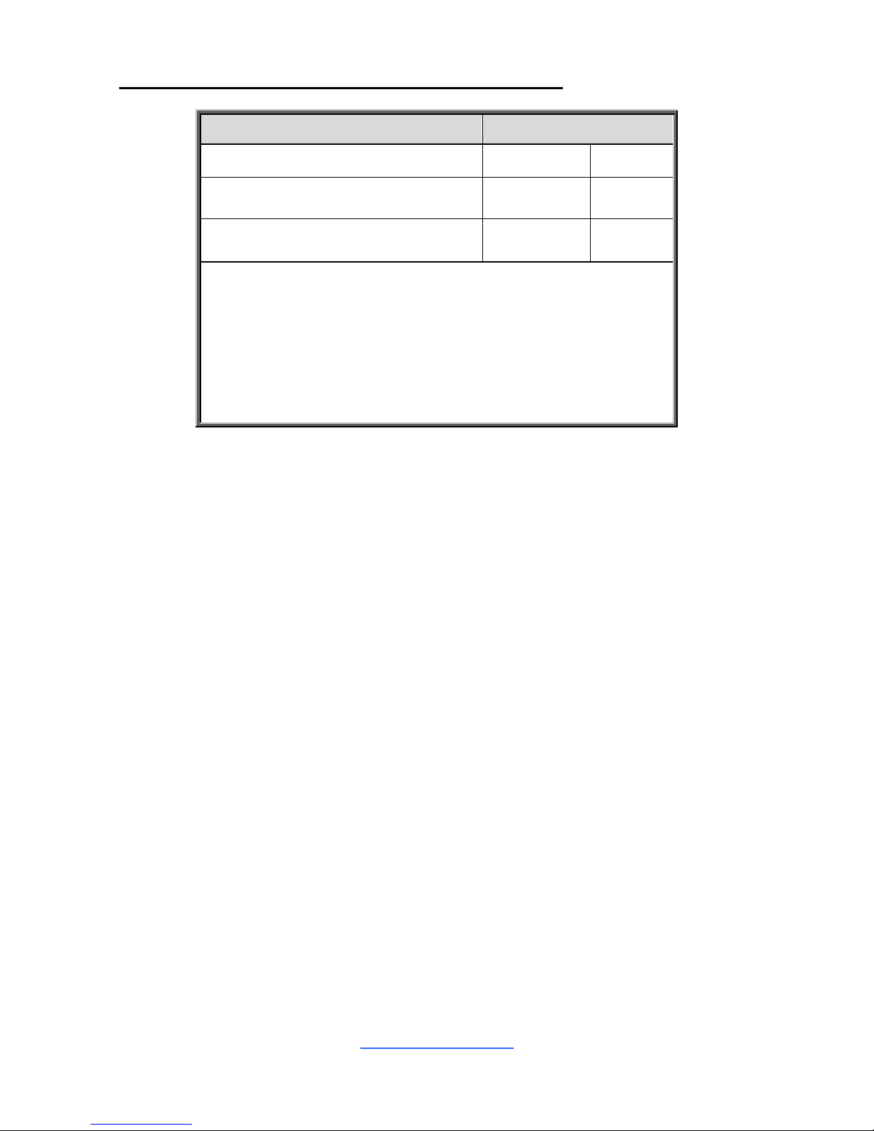
Recommended Memory Population Table (Single CPU)
Single CPU Installed
Quantity of memory installed
1
2
CPU_DIMM_A0
√
CPU_DIMM_B0
√
√
NOTE:
1.√ indicates a populated DIMM slot.
2. Use paired memory installation for max performance.
3. Populate the same DIMM type in each channel,
specifically
- Use the same DIMM size
- Use the same # of ranks per DIMM
http://www.tyan.com
24
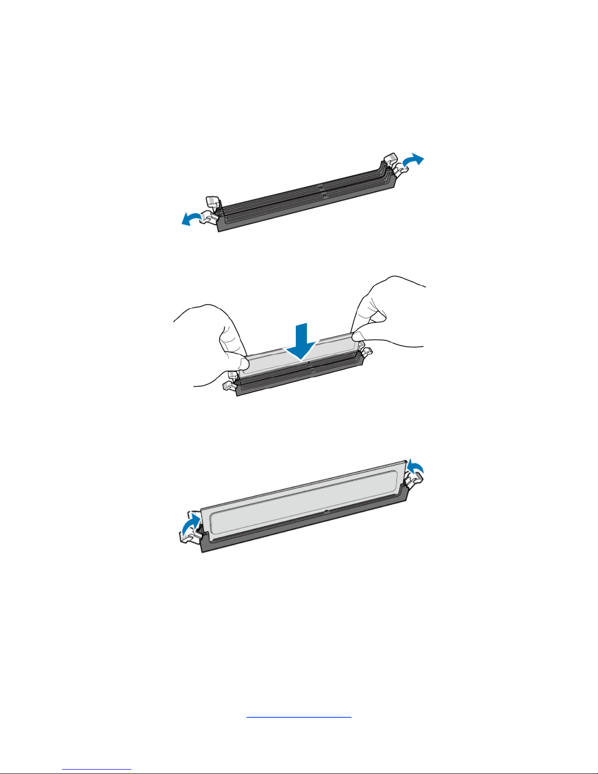
Memory Installation Procedure
Follow these instructions to install memory modules into the S5547.
1. Unlock a DIMM socket by Press the retaining clip outwardly in the following
illustration.
2. Align the memory module with the socket,such that the DIMM NOTCH match
the KEY SLOT on the socket.
3. Seat the module firmly into the socket by gently pressing down until it sits
flush with the socket. The locking levers pop up into place.
http://www.tyan.com
25
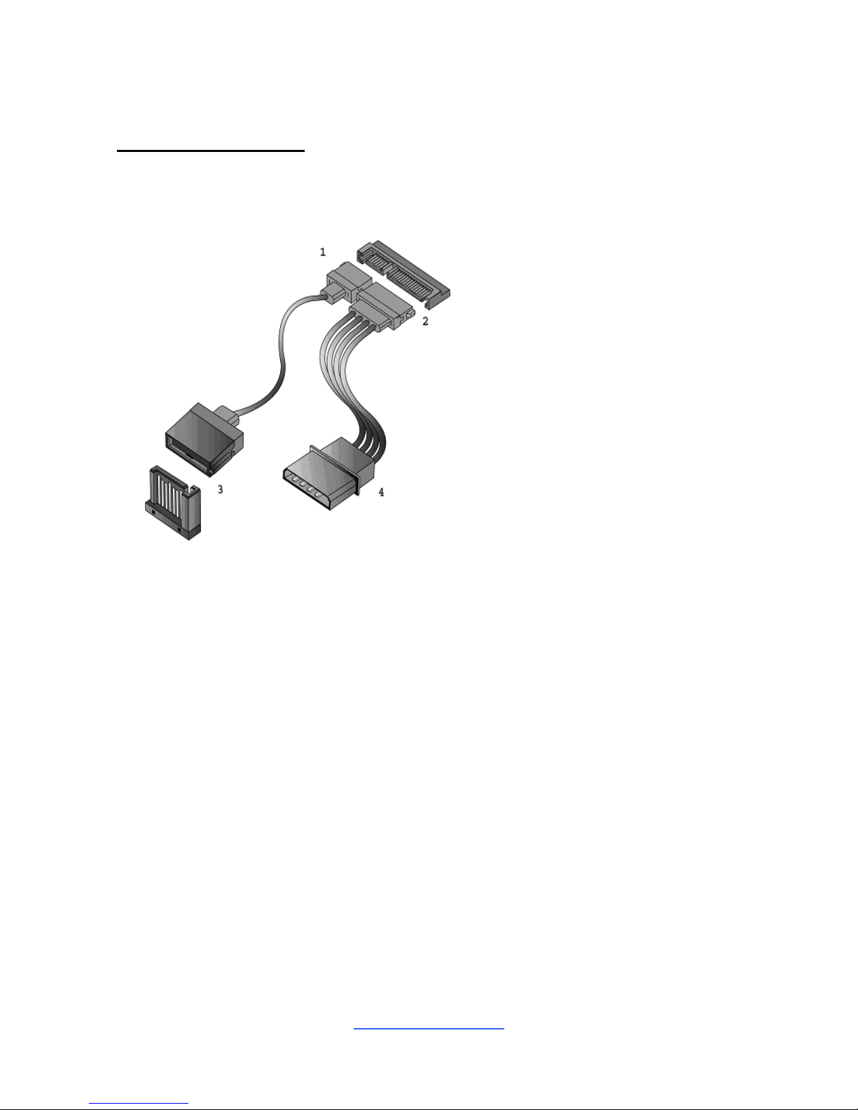
2.8 Attaching Drive Cables
Attaching SATA Cables
The following illustrates how to make a SATA Cable connection. If you are in need
of SATA/SAS cables or power adapters please contact your local sales
representative.
1. SATA drive cable
connection
2. SATA drive power connection
3. SATA cable motherboard
connector
4. SATA drive power adapter
http://www.tyan.com
26
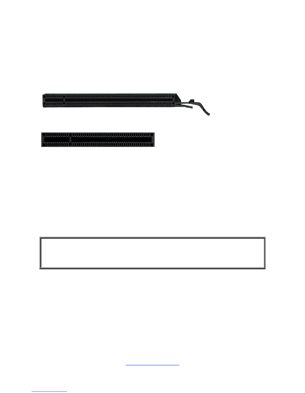
2.9 Installing Add-In Cards
Before installing add-in cards, it‟s helpful to know if they are fully compatible with
your motherboard. For this reason, we‟ve provided the diagrams below, showing
the slots that may appear on your motherboard.
PCI-E x 16 slot
PCI-E x 8 slot
Simply find the appropriate slot for your add-in card and insert the card firmly. Do
not force any add-in cards into any slots if they do not seat in place. It is better to try
another slot or return the faulty card rather than damaging both the motherboard
and the add-in card.
TIP: It‟s a good practice to install add-in cards in a staggered manner rather than
making them directly adjacent to each other. Doing so allows air to circulate within
the chassis more easily, thus improving cooling for all installed devices.
NOTE: You must always unplug the power connector from the motherboard
before performing system hardware changes to avoid damaging the board or
expansion device.
http://www.tyan.com
27
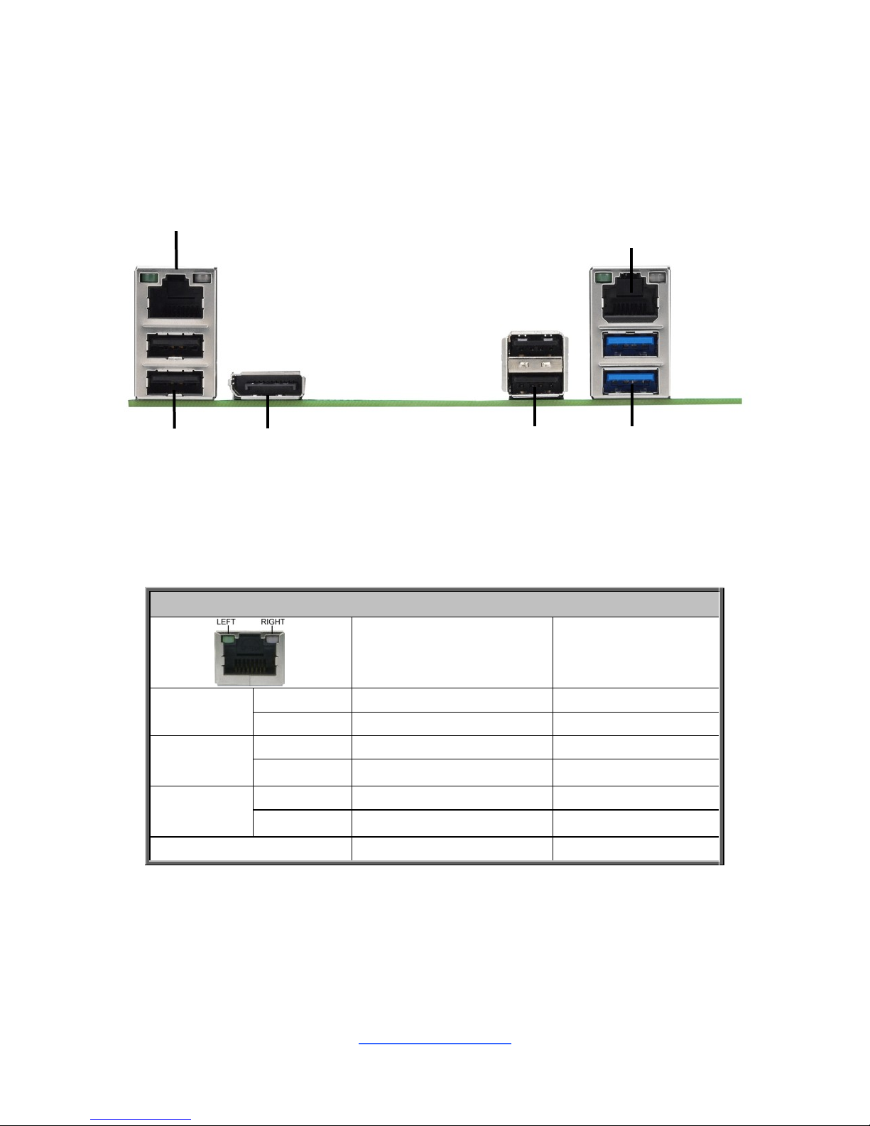
2.10 Connecting External Devices
Connecting external devices to the motherboard is an easy task. The motherboard
supports a number of different interfaces through connecting peripherals. See the
following diagrams for the details.
Onboard LAN LED Color Definition
The two (2) onboard Ethernet ports have green and yellow LEDs to indicate LAN
status. The chart below illustrates the different LED states.
10/100/1000 Mbps LAN Link/Activity LED Scheme
Left LED
Right LED
10 Mbps
Link
Green
Off
Active
Blinking Green
Off
100 Mbps
Link
Green
Green
Active
Blinking Green
Green
1000 Mbps
Link
Green
Amber
Active
Blinking Green
Amber
No Link
Off
Off
USB3.0x2
USB2.0x2
Display Port
LAN1 (I210)
LAN2 (I219)
USB2.0x2
http://www.tyan.com
28
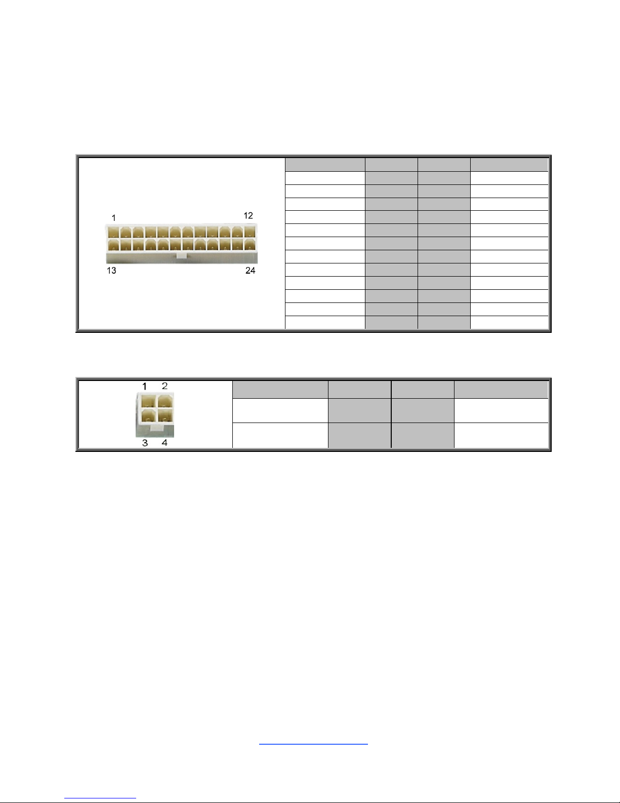
2.11 Installing the Power Supply
There are Two (2) power connectors on your S5547 motherboard. The S5547
supports EPS 12V power supply.
J24: 24-Pin Power Connector
Signal
Pin
Pin
Signal
V3P3
1
13
V3P3
V3P3
2
14
-12V
GND
3
15
GND
+5V
4
16
PS_ON#
GND
5
17
GND
+5V
6
18
GND
GND
7
19
GND
PWROK
8
20
NC
5VSB
9
21
+5V
+12V
10
22
+5V
+12V
11
23
+5V
V3P3
12
24
GND
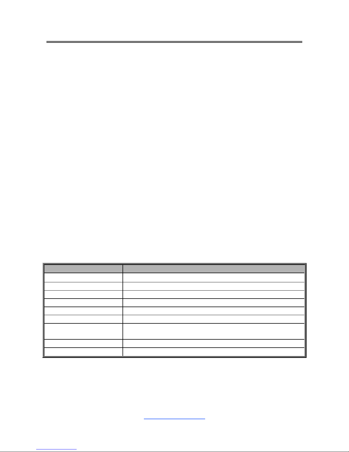
PWRCONN1: ATX 4-pin Power Connector
Signal
Pin
Pin
Signal
GND
1
3
VCC12_2
GND
2
4
VCC12_2
2.12 Finishing Up
Congratulations on making it this far! You have finished setting up the hardware
aspect of your computer. Before closing up your chassis, make sure that all cables
and wires are connected properly, especially SATA cables and most importantly,
jumpers. You may have difficulty powering on your system if the motherboard
jumpers are not set correctly.
In the rare circumstance that you have experienced difficulty, you can find help by
asking your vendor for assistance. If they are not available for assistance, please find
setup information and documentation online at our website or by calling your vendor‟s
support line.
http://www.tyan.com
29
Chapter 3: BIOS Setup
3.1 About the BIOS
The BIOS is the basic input/output system, the firmware on the motherboard that
enables your hardware to interface with your software. The BIOS determines what a
computer can do without accessing programs from a disk. The BIOS contains all
the code required to control the keyboard, display screen, disk drives, serial
communications, and a number of miscellaneous functions. This chapter describes
the various BIOS settings that can be used to configure your system.
The BIOS section of this manual is subject to change without notice and is provided
for reference purposes only. The settings and configurations of the BIOS are
current at the time of print and are subject to change, and therefore may not match
exactly what is displayed on screen.
This section describes the BIOS setup program. The setup program lets you modify
basic configuration settings. The settings are then stored in a dedicated, batterybacked memory (called NVRAM) that retains the information even when the power
is turned off.
To start the BIOS setup utility:
1. Turn on or reboot your system.
2. Press <Del> during POST to start the BIOS setup utility.
3.1.1 Setup Basics
The table below shows how to navigate in the setup program using the keyboard.
Key
Function
↑↓
Move cursor
<Enter>
Execute command or select submenu
<->/<+>
Select the previous or next value/setting of the field
<ESC>
Exit current menu
<F1>
General help
<F2>
Previous values
<F3>
Load the Optimal default configuration values of the
menu
<F4>
Save and exit
<PgUp> / <PgDn>
Move cursor to next/previous page
 Loading...