

TYAN S5530 User Manual

http://www.tyan.com
1
S5530
Version 1.0
Copyright
Copyright © 2013 MiTAC International Corporation. All rights reserved. No part of
this manual may be reproduced or translated without prior written consent from
MiTAC International Corporation.
Trademark
All registered and unregistered trademarks and company names contained in this
manual are property of their respective owners including, but not limited to the
following.
TYAN® is a trademark of MiTAC International Corporation.
Intel
®
is a trademark of Intel® Corporation.
AMI, AMI BIOS are trademarks of AMI Technologies.
Microsoft®, Windows® are trademarks of Microsoft Corporation.
Winbond
®
is a trademark of Winbond Electronics Corporation.
Notice
Information contained in this document is furnished by MiTAC International
Corporation and has been reviewed for accuracy and reliability prior to printing.
MiTAC assumes no liability whatsoever, and disclaims any express or implied
warranty, relating to sale and/or use of TYAN
®
products including liability or
warranties relating to fitness for a particular purpose or merchantability. MiT A C
retains the right to make changes to product descriptions and/or specifications at
any time, without notice. In no event will MiTAC be held liable for any direc t or
indirect, incidental or consequential damage, loss of use, loss of data or other
malady resulting from errors or inaccuracies of information contained in this
document.

http://www.tyan.com
2
About this guide
This user guide contains the information you need when inst alling and configuring
the motherboard.
How this guide is organized
This guide contains the following parts:
Chapter1: Instruction
This chapter describes the features of the motherboard and the new technology it
supports.
Chapter2: Board Installation
This chapter lists the hardware setup procedures that you need to abide by when
installing system components. It includes description of the jumpers and connectors
on the motherboard.
Chapter3: BIOS Setup
This chapter tells how to change system settings through the BIOS setup menu.
Detailed descriptions of the BIOS parameters are also provided.
Chapter4: Diagnostics
This chapter introduces some BIOS codes and technical terms to provide better
service for the customers.
Appendix I: Fan and Temp Sensors
This section aims to help readers identify the locations of some specific Fan and
Temp Sensors on the motherboard. A table of BIOS Temp sensor name
explanation is also included for readers’ reference.

http://www.tyan.com
3
Contents
Before you begin…....................................................................................4
Chapter 1: Instruction ................................................................................5
1.1 Congratulations .................................................................................5
1.2 Hardware Specification......................................................................5
1.3 Software Specifications.....................................................................7
Chapter 2: Board Installation..................................................................... 9
2.1 Board Image....................................................................................10
2.2 Block Diagram.................................................................................11
2.3 Mainboard Mechanical Drawing......................................................12
2.4 Board Parts, Jumpers and Connectors...........................................13
2.5 Installing the Processor and Heatsink.............................................25
2.6 Thermal Interface Material ..............................................................29
2.7 Tips on Installing Motherboard in Chassis ......................................30
2.8 Installing the Memory ......................................................................32
2.9 Attaching Drive Cables....................................................................36
2.10 Installing Add-In Cards..................................................................37
2.11 Connecting External Devices ........................................................38
2.12 Installing the Power Supply...........................................................40
2.13 Finishing Up...................................................................................41
Chapter 3: BIOS Setup ............................................................................. 43
3.1 About the BIOS................................................................................43
3.2 Main Menu.......................................................................................45
3.3 Advanced Menu...............................................................................46
3.4 Chipset Menu ..................................................................................74
3.5 Boot .................................................................................................84
3.6 Security............................................................................................87
3.7 Server Management........................................................................88
3.8 Save & Exit......................................................................................90
Chapter 4: Diagnostics............................................................................. 93
4.1 Flash Utility......................................................................................93
4.2 AMIBIOS Post Code (Aptio)............................................................94
Appendix I: Fan and Temp Sensors .....................................................101
Glossary................................................................................................... 105
Technical Support ..................................................................................111
http://www.tyan.com
4
Before you begin…
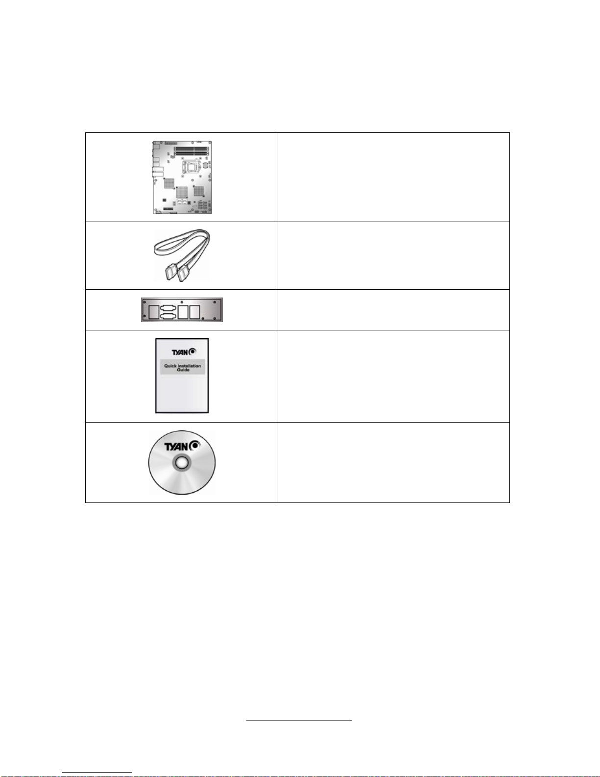
Check the box contents!
The retail motherboard package should contain the following:
1 x S5530 Motherboard
6 x SATA Single Cable
1 x IO shield
1 x S5530 Quick Installation Guide
1 x TYAN® Driver CD
IMPORTANT NOTE:
Sales samples may not come with any of the accessories listed above.
If you have ordered a sales sample and you are missing any of the above i tems,
please contact your sales representative to help order accessories.

http://www.tyan.com
5
Chapter 1: Instruction
1.1 Congratulations
You have purchased the powerful TYAN® S5530 motherboard, based on the
Intel
®
C222 chipset. The S5530 is designed to support single Intel® Xeon E3-
1200 v3, i3 (22nm/Haswell)
series processor, and up to 32GB Unbuffered ECC
DDR3 1600/1333/1066 memory. Leveraging advanced technology from Intel
®
,
the S5530 is capable of offering scalable 32 and 64-bit computing, highbandwidth memory design, and lightning-fast PCI-E bus implementation.
The S5530 not only empowers you in today’s demand ing IT environment but also
offers a smooth path for future application upgradeability. All of these rich feature
sets provide the S5530 with the power and flexibility to meet demanding
requirements for today’s IT environments.
Remember to visit the TYAN® website at http://www.tyan.com. There you can find
all the information on all TYAN
®
products as well as all the supporting
documentation, FAQs, Drivers and BIOS upgrades.
1.2 Hardware Specification
TYAN S5530 (S5530WGM5NR-LE-2T)
Supported CPU
Series
Intel Xeon E3-1200 v3, i3 (22nm/Haswell) series
processors
Socket Type / Q'ty LGA 1150/ (1)
Processor
Thermal Design
Power (TDP)
wattage
Max up to 95W
Chipset PCH Intel C222
Supported DIMM
Qty
(4) DIMM slots
DIMM Type / Speed Unbuffered ECC DDR3 1600/1333/1066
Memory
Capacity Up to 32GB
Expansion Slots PCI-E (1) PCI-E Gen2 x4 slot
Recommended
Barebone /
Chassis
Mechanical
Compliant
KGT20 / KGT62A
Port Q'ty
(2) 10GbE SFP+ + (3) GbE RJ45 (1 port shared
with IPMI)
Controller Intel I210 / Broadcom BCM57810S
LAN
PHY Intel I217
http://www.tyan.com
6
Connector (2) Mini-SAS connectors (totally support 8 ports)
Controller LSI SAS2008
Speed 6.0 Gb/s
SAS
RAID RAID 0/1/1E/10 (LSI Integrated RAID)
Connector (6) SATA
Controller Intel C222
Speed (2) 6.0 Gb/s (blue color), (4) 3.0 Gb/s (black color)
Storage
SATA
RAID RAID 0/1/10/5 (Intel RST)
Connector type D-Sub 15-pin
Graphic
Chipset Aspeed AST2300
USB
(2) USB3.0 ports (2 at rear)+(3) USB2.0 ports (2
via cable, Type-A)
COM
(1) DB-9 COM Connector (at rear, COM1) + (1)
Header (COM2)
SAS (2) Mini-SAS (4-in-1) connectors
VGA (1) D-Sub 15-pin VGA port
RJ-45 Total (3) GbE ports, (1) shared with IPMI
SFP+ (2) 10GbE ports
Input /Output
SATA (4) SATA-II and (2) SATA-III connectors
Chipset Aspeed AST2300
Voltage
Monitors voltage for CPU, memory, chipset &
power supply
Fan Total (5) 4-pin headers
Temperature Monitors temperature for CPU & memory
LED
Fan fail LED indicator / Over temperature warning
indicator
System
Monitoring
Others Watchdog timer support
Onboard Chipset Onboard Aspeed AST2300
AST2300 IPMI
Feature
IPMI 2.0 compliant baseboard management
controller (BMC) / Supports storage over IP and
remote platform-flash / USB 2.0 virtual hub
Server
Management
AST2300 iKVM
Feature
24-bit high quality video compression / 10/100
Mb/s MAC interface
Brand / ROM size AMI / 16MB
BIOS
Feature
Plug and Play (PnP) /PCI2.3 /WfM2.0 /SMBIOS2.3
/PXE boot / ACPI 2.0 power management /Power
on mode after power recovery / User-configurable
H/W monitoring / Auto-configurable of hard disk
types
Form Factor ATX
Physical
Dimension
Board Dimension 12"x9.6" (305x243.8mm)
Operating System OS supported list Please refer to our Intel OS supported list.
FCC (DoC) Class A
Regulation
CE (DoC) Yes

http://www.tyan.com
7
Operating Temp. 10° C ~ 35° C (50° F~ 95° F)
Non-operating
Temp.
- 40° C ~ 70° C (-40° F ~ 158° F)
Operating
Environment
In/Non-operating
Humidity
90%, non-condensing at 35° C
RoHS RoHS 6/6 Compliant Yes
Motherboard (1) S5530 Motherboard
Manual (1) Quick Installation Guide
Installation CD (1) TYAN installation CD
I/O Shield (1) I/O Shield
Package Contains
Cable SATA (6) SATA signal cables
1.3 Software Specifications
For the latest OS (operation system) support and IPMI Configuration Guide, please
visit our Web site for information.

http://www.tyan.com
8
NOTE
http://www.tyan.com
9
Chapter 2: Board Installation
You are now ready to install your motherboard.
How to install our products right… the first time
The first thing you should do is read this user’s manual. It contains important
information that will make configuration and setup much easier. Here are some
precautions you should take when installing your motherboard:
(1) Ground yourself properly before removing your motherboard from the
antistatic bag. Unplug the power from your computer power supply and
then touch a safely grounded object to release static charge (i.e. power
supply case). For the safest conditions, MiTAC recommends wearing a
static safety wrist strap.
(2) Hold the motherboard by its edges and do not touch the bottom of the
board, or flex the board in any way.
(3) Avoid touching the motherboard components, IC chips, connectors,
memory modules, and leads.
(4) Place the motherboard on a grounded antistatic surface or on the antist ati c
bag that the board was shipped in.
(5) Inspect the board for damage.
The following pages include details on how to install your motherboard into your
chassis, as well as installing the processor, memory, disk drives and cables.
Caution!
1. To avoid damagin g the motherboard and associated
components, do not use torque force greater than
7kgf/cm (6.09 lb/in) on each mounting screw for
motherboard installation.
2. Do not apply power to the board if it has been
damaged.
http://www.tyan.com
10
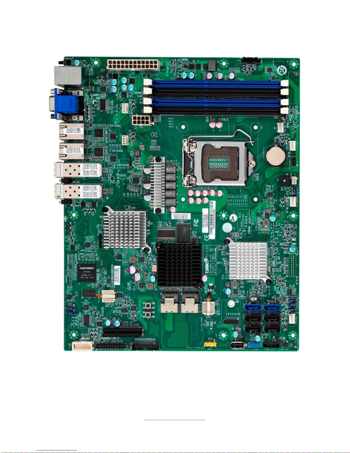
2.1 Board Image
S5530
This picture is representative of the latest board revision available at the time of
publishing. The board you receive may not look exactly like the above picture.
http://www.tyan.com
11
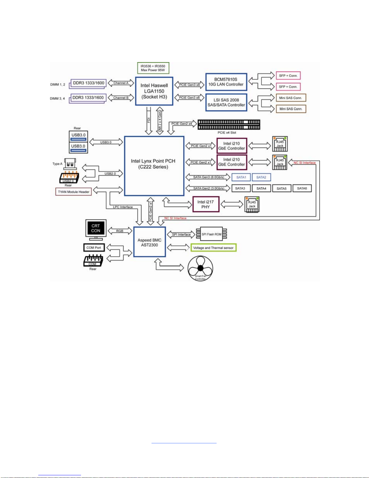
2.2 Block Diagram
S5530 Block Diagram
http://www.tyan.com
12
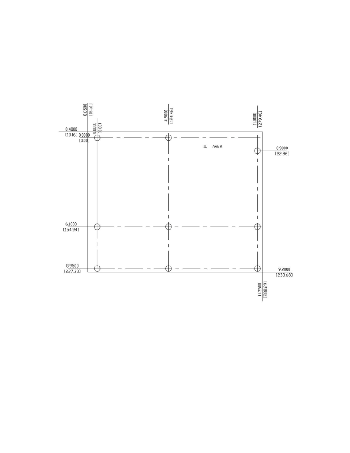
2.3 Mainboard Mechanical Drawing
http://www.tyan.com
13
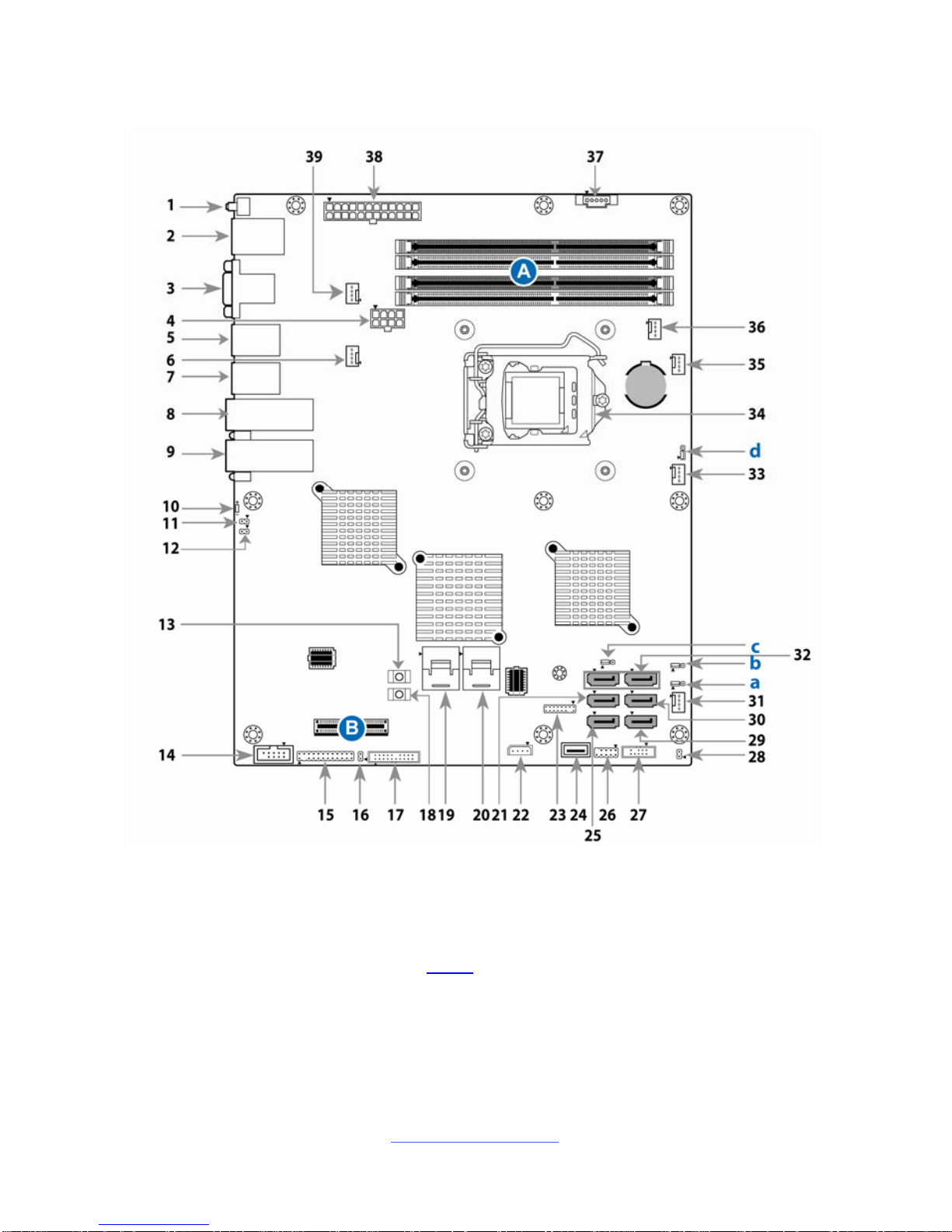
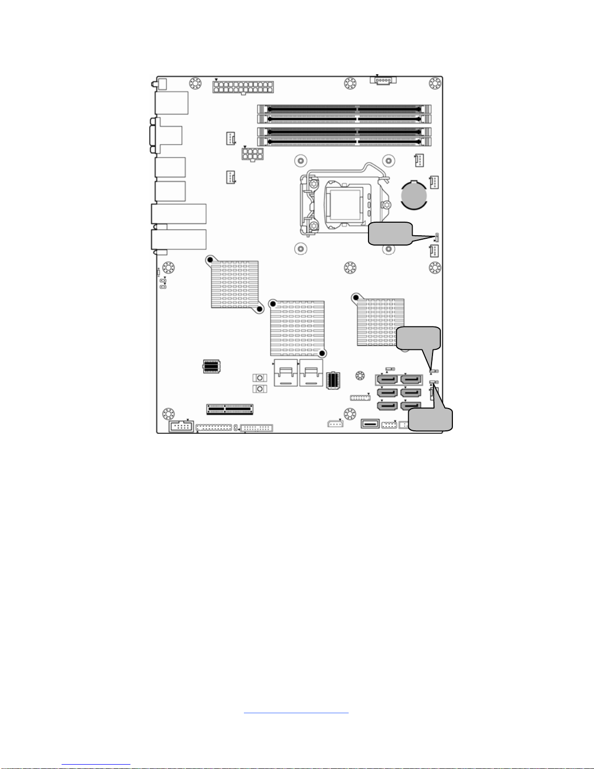
2.4 Board Parts, Jumpers and Connectors
This diagram is representative of the latest board revision available at the time of
publishing. The board you receive may not look exactly like the above diagram. The
DIMM slot numbers shown above can be used as a reference when reviewing the
DIMM population guidelines shown later in the manual. For the latest board
revision, please visit our web site at http://
www.tyan.com.
http://www.tyan.com
14
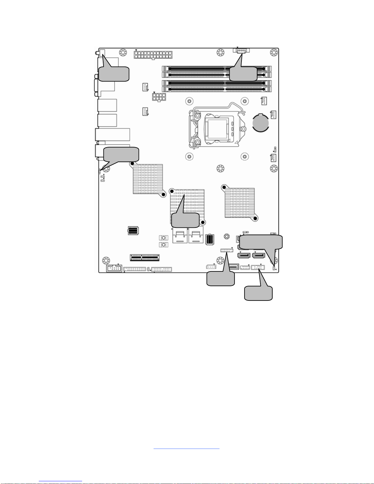
Connectors, Jumpers & Slots
Connector/Jumper
1 ID LED Button (SW1) 21 SATA2.0 Connector (SATA2, J39)
2 LAN Port # 3 (LAN3) / USB 3.0 Port x 2 22 IPMB Connector (J29)
3 COM1 Port / VGA Port 23 TYAN Module Header (J35)
4 SSI 8-pin CPU Power Connector 24 Vertical Type-A USB Connector (J34)
5 LAN Port # 2 (LAN2) 25 SATA2.0 Connector (SATA4, J40)
6 Fan Connector (SYS_FAN_5, J19) 26 USB Front Panel Header (J43)
7 LAN Port # 1 (LAN1) 27 SATA SGPIO Header (HBA)
8 SFP+ Port # 1 (J12) 28 Chassis Intrusion Header (INTRD1)
9 SFP+ Port # 0 (J11) 29 SATA2.0 Connector (SATA5, J59)
10 ID LED (LED1) 30 SATA2.0 Connector (SATA3, J45)
11 SFP+ Port # 0 LED (J3, LED3) 31 Fan Connector (SYS_FAN_3, J55)
12 SFP+ Port # 1 LED (J2, LED2)
32 SATA3.0 Connector (SATA0~1,
J38/J44)
13 Reset Button (J25) 33 Fan Connector (SYS_FAN_2, J56)
14 COM2 Header (J10) 34 CPU Socket (CPU0, U46)
15 Front Panel Header (J13) 35 Fan Connector (SYS_FAN_1, J54)
16 LAN3 LED Header (J22) 36 CPU FAN Connector (J48)
17 Reserved for BB FAN Board (J23) 37 PSMI Connector (J36)
18 Power Button (J20) 38 ATX 24-pin Power Connector (J18)
19 Mini SAS Connector (SAS Port 1, J26) 39 Fan Connector (SYS_FAN_4, J20)
20 Mini SAS Connector (SAS Port 0, J27)
Jumpers Slots
a ME Firmware Update Jumper (J50) A DIMM Slots [Channel 1 / 2 / 3 / 4]
b BIOS Recovery Mode Jumper (J52) B PCIE slot (x4)
c Clear CMOS Jumper (J42)
d ME Recovery Mode Jumper (J59)
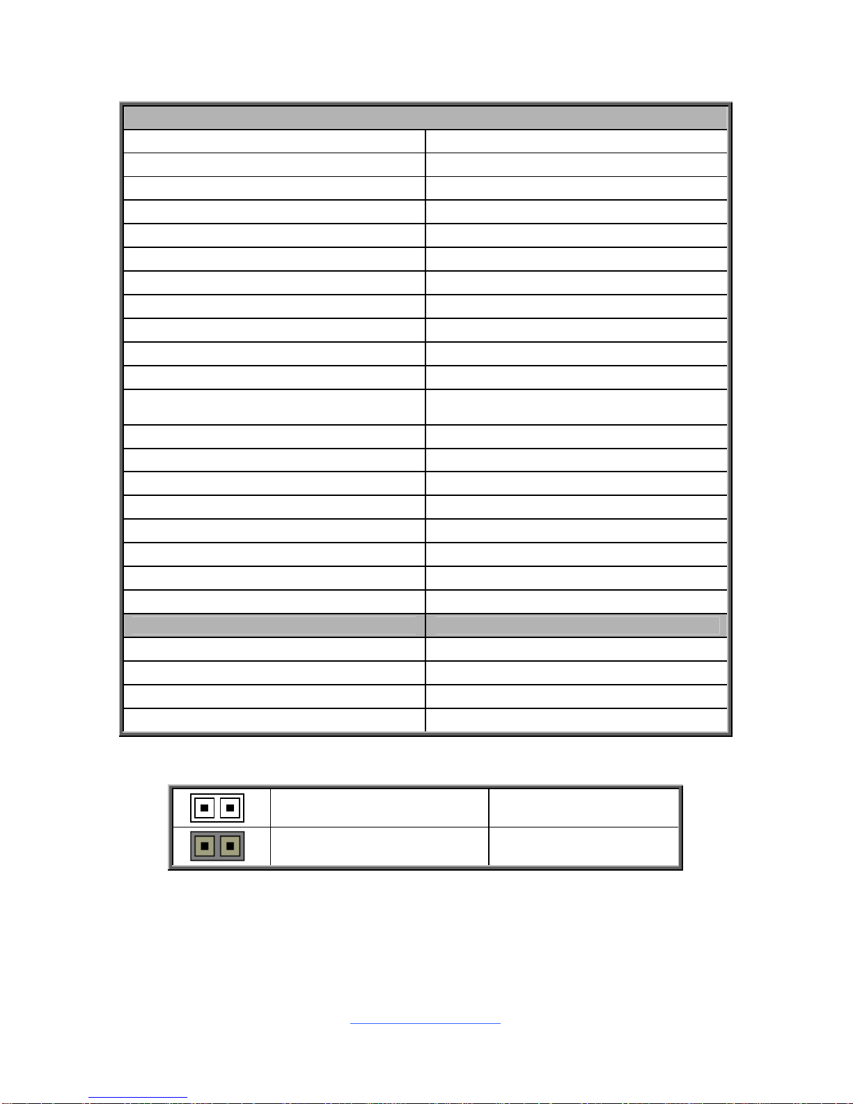
Jumper Legend
OPEN - Jumper OFF
Without jumper cover
CLOSED - Jumper ON
With jumper cover
http://www.tyan.com
15
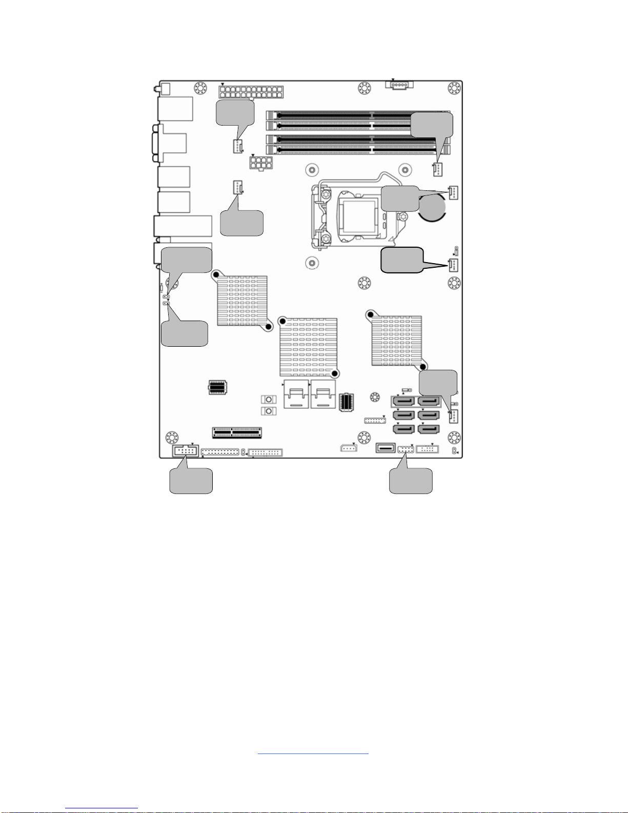
J19
J48
J54
J56
J20
J55
J10
LED3
LED2
J43
http://www.tyan.com
16
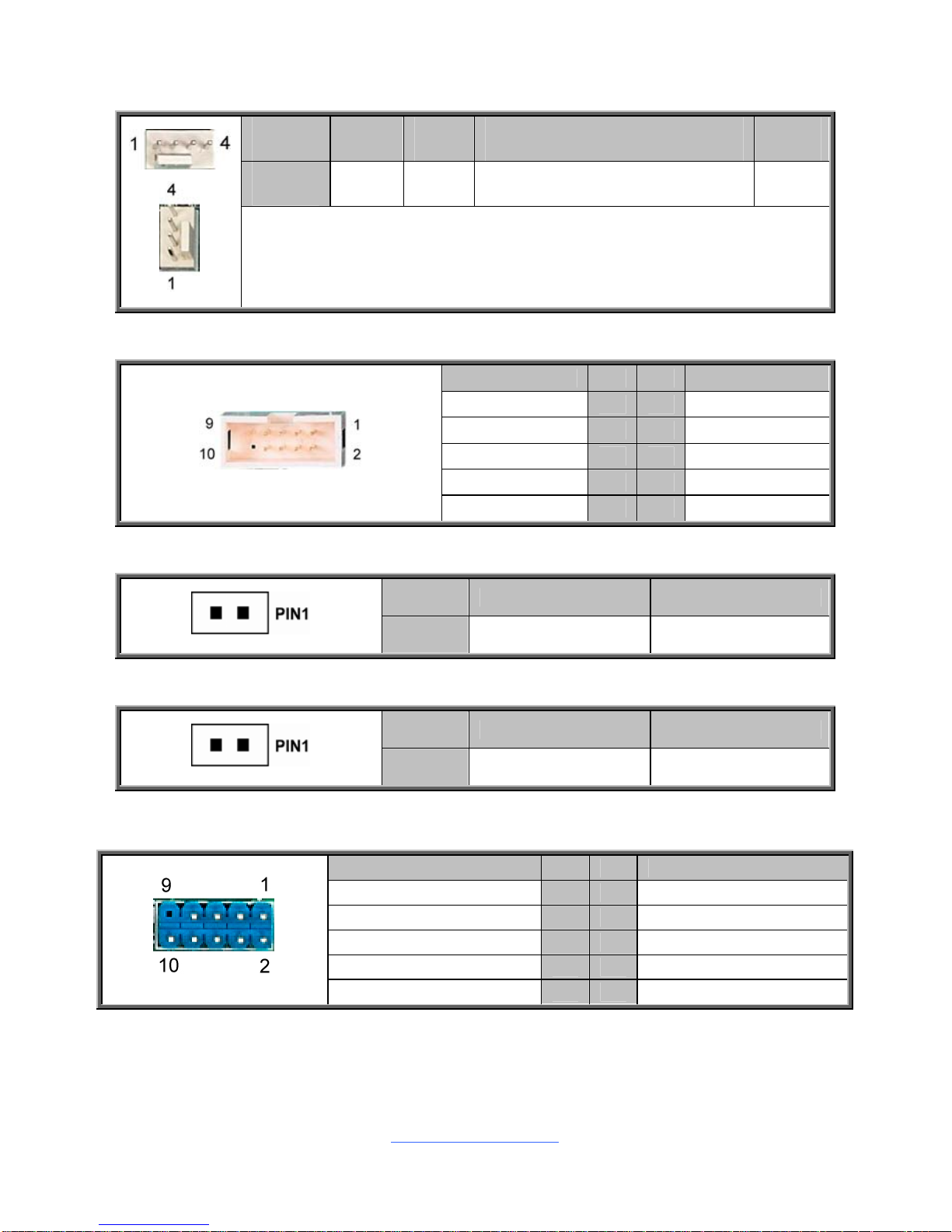
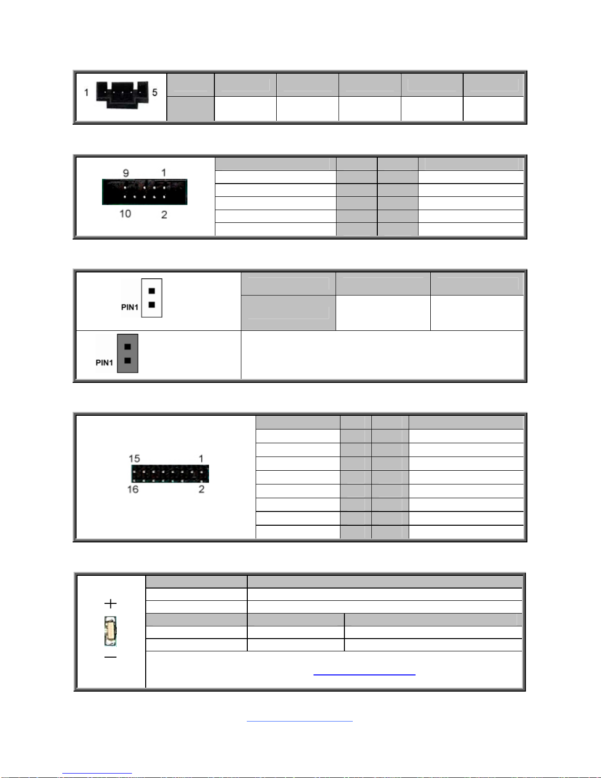
J19/J20//J48/J54/J55/J56: 4-Pin FAN Connector
Pin 1 2 3 4
Signal GND VCC TACHOMETER PWM
Use this header to connect the cooling fan to your motherboard to keep the
system stable and reliable.
J19: SYS_FAN_5 J20: SYS_FAN_4 J48: CPU_FAN
J54: SYS_FAN_1 J55: SYS_FAN_3 J56: SYS_FAN_2
J10: COM2 Header
Signal Pin Pin Signal
DCD 1 2 DSR
RXD 3 4 RTS
TXD 5 6 CTS
DTR 7 8 NRI
GND 9 10 NONE
J3: SFP+ Port # 0 LED (LED3)
Pin 1 2
Signal VCC LED_PO_ACT_N
J2: SFP+ Port # 1 LED (LED2)
Pin 1 2
Signal VCC LED_PO_ACT_N
J43: USB Front Panel Header (blue)
Signal Pin Pin Signal
VCC 1 2 VCC
USB2_PCH_P4N_L 3 4 USB2_PCH_P5N_L
USB2_PCH_P4P_L 5 6 USB2_PCH_P5P_L
GND 7 8 GND
NONE 9 10
N/A
http://www.tyan.com
17
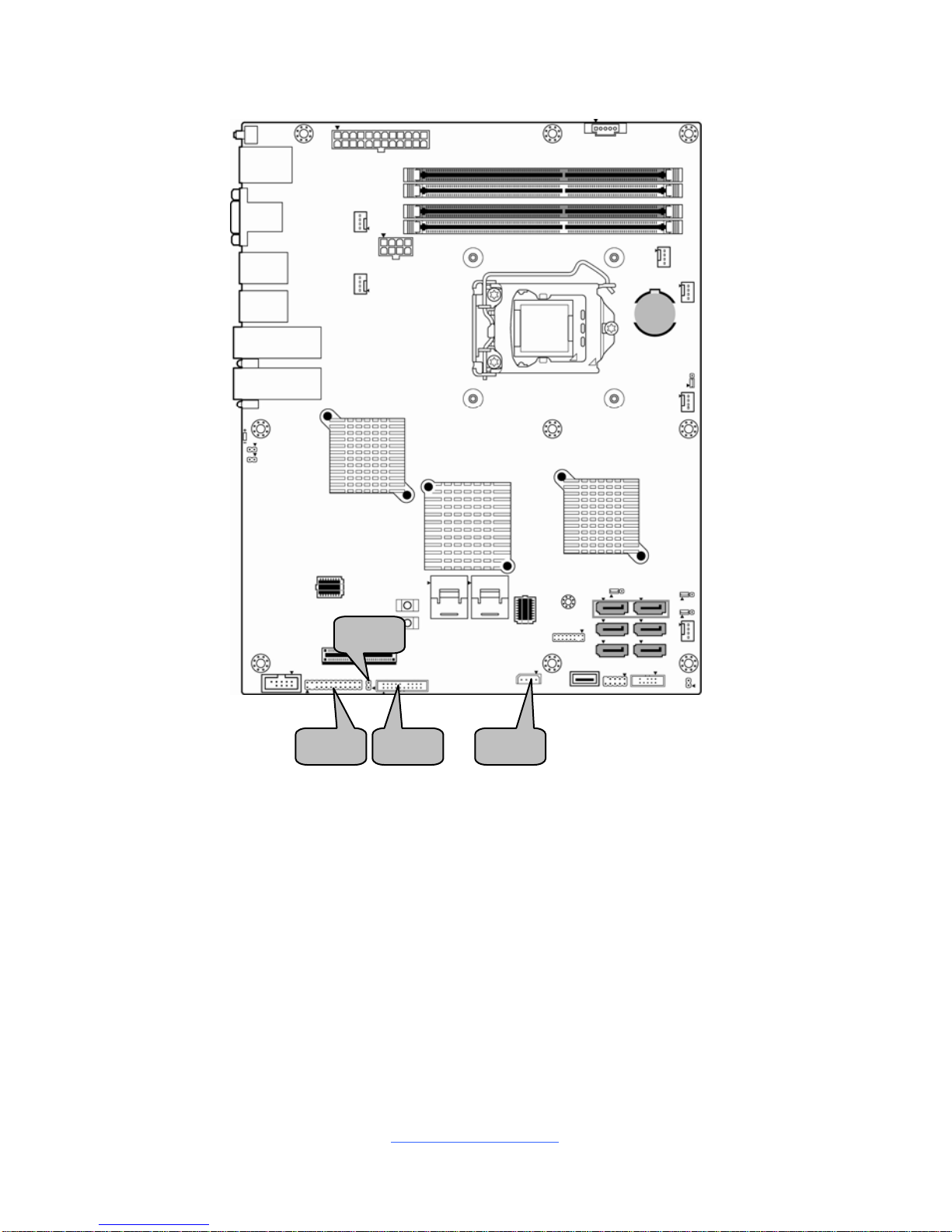
J23J13
J22
J29
http://www.tyan.com
18
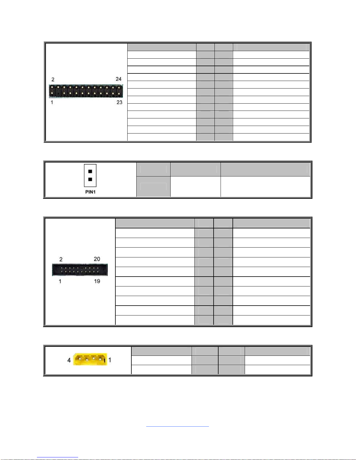
J13: Front Panel Header
Signal Pin Pin Signal
FP_PLED+ 1 2 DSR
NONE 3 4 BMC_ID_LED+
PWR_LED- 5 6 GND
HDD_LED+ 7 8 LED_FAULT1
HDD_LED- 9 10 LED_FAULT2
FP_PWRSW# 11 12 LAN0_ACT_P
GND 13 14 LED_LAN1_ACT#
FP_RSTSW# 15 16 FP_SMBDAT
GND 17 18 FP_SMBCLK
FP_IDLEDSW# 19 20 FP_INTRUSION#
N/A 21 22 LAN1_ACT_P
FP_NMIBTN# 23 24 LED_LAN2_ACT#
J22: LAN3 LED Header
Pin 1 2
Signal VCC LAN3_LINK_ACTIVITY#
J23: Front Fan Connector (Reserved for Barebone Fan Board)
Signal Pin Pin Signal
SYS_FAN_TACH2_20P 1 2 SYS_FAN_TACH7_20P
SYS_FAN_TACH3_20P 3 4 SYS_FAN_TACH8_20P
SYS_FAN_TACH4_20P 5 6 SYS_FAN_TACH9_20P
SYS_FAN_TACH5_20P 7 8 SYS_FAN_TACH10_20P
SYS_FAN_TACH6_20P 9 10 SYS_FAN_TACH11_20P
GND 11 12 NONE
SYS_FAN4_PWM_20P 13 14 SYS_FAN_PWM3_20P
SYS_FAN_TACH12_20P 15 16 BMC_SMB_DAT3_20P
SYS_FAN_TACH13_20P 17 18 BMC_SMB_CLK3_20P
VCC 19 20 SYS_FAN_PWM5_20P
J29: IPMB Connector
Signal Pin Pin Signal
IPMB_SMB_DATA 1 2 GND
IPMB_SMB_CLK 3 4 N/A
http://www.tyan.com
19
J36
INTRD1
J35
J29
J47
SW1
LED1
http://www.tyan.com
20
J36: PSMI Connector
Pin 1 2 3 4 5
Signal
PSMI
SLK
PSMI
DATA
PSMI
ALERT
GND VCC
J47 (HBA): SATA SGPIO Header for BB HD Board
Signal Pin Pin Signal
SCL 1 2 SD1/SDO1
NONE 3 4 SDO0
SDA 5 6 SLOAD
GND 7 8 SCLOCK
VCC 9 10 HDD_FAULT
INTRD1: Chassis Intrusion Header
Pin 1 2
Open
Signal GND INTRUDER
Short (Default)
Open: Use this header to trigger the system chassis
intrusion alarm.
Short: Use this header to disable the system chassis
intrusion alarm.
J35: TYAN Module Header
Signal Pin Pin Signal
VCC3 1 2 LPC_LFRAME#
LPC_LAD0 3 4 NONE
LPC_LAD1 5 6 PLTRST_TPM#
LPC_LAD2 7 8 GND
LPC_LAD3 9 10 CLK_33M_PCH_TPM
LPC_LSIRQ0# 11 12 GND
TPM_PRSNT 13 14 VCC
N/A 15 16 N/A
LED1 / SW1: ID LED and ID LED Button
Pin Signal
+ P3V3_AUX
- ID_SW_L
State Color Description
On Blue System identified
Off Off System not identified
NOTE: The ID LED can be activated remotely using IPMI.
Please visit the TYAN Web Site at http://www.tyan.com
to download the
latest IPMI Configuration Guide for more details.
http://www.tyan.com
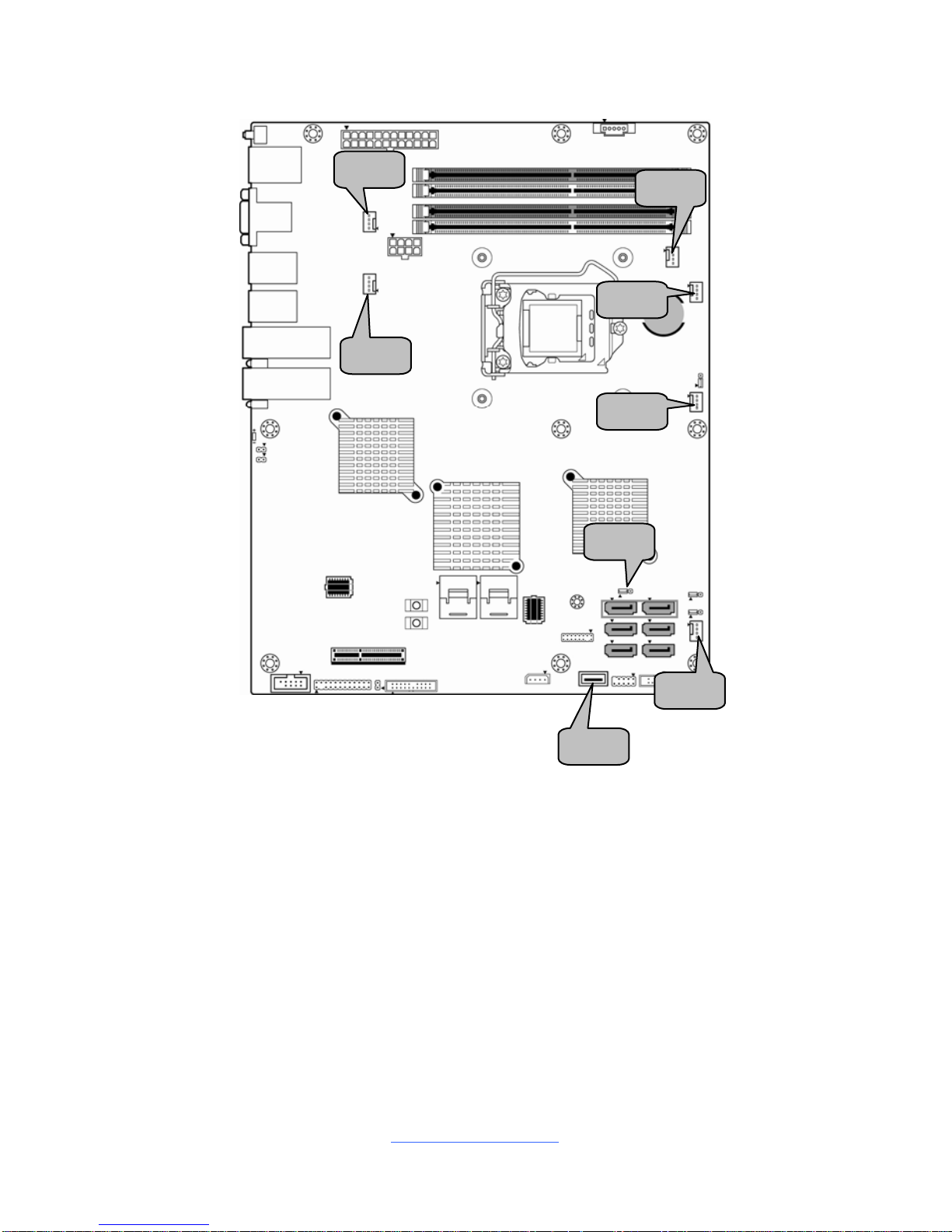
21
J56
J42
J20
J19
J55
J34
J54
J48
http://www.tyan.com
22
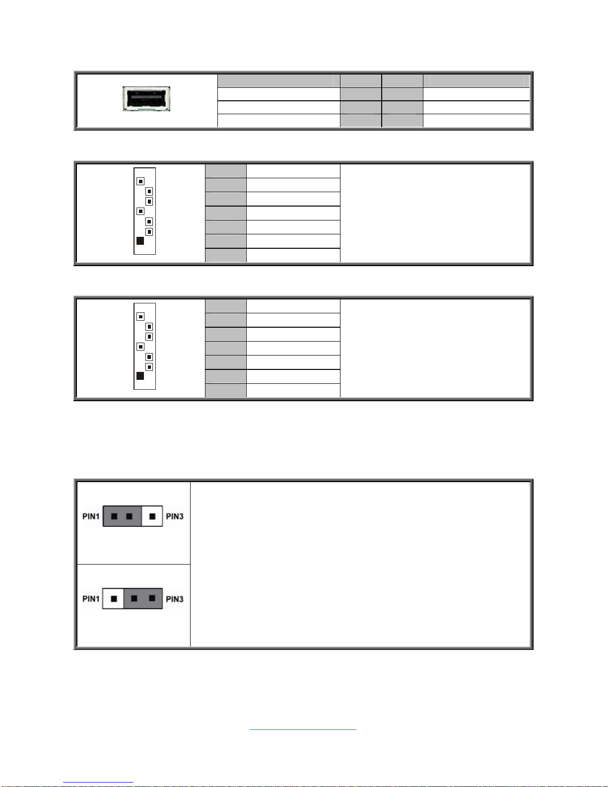
J34: Vertical Type-A USB Connector
Signal Pin Pin Signal
VCC 1 2 N/A
GND 3 4 GND
BCM_UART_TXD 5 6 BCM_UART_RXD
J39/J45/J40/J59: SATA2.0 Connector
1 GND
2 SATA TX DP
3 SATA TX DN
4 GND
5 SATA RX DN
6 SATA RX DP
7
1
7 GND
Connects to the Serial ATA ready
drives via the Serial ATA cable.
J39: SATA2 J40: SATA4
J45: SATA3 J59: SATA5
J38/J44: SATA3.0 Connector
1 GND
2 SATA TX DP
3 SATA TX DN
4 GND
5 SATA RX DN
6 SATA RX DP
7
1
7 GND
Connects to the Serial ATA ready
drives via the Serial ATA cable.
J38: SATA0
J44: SATA1
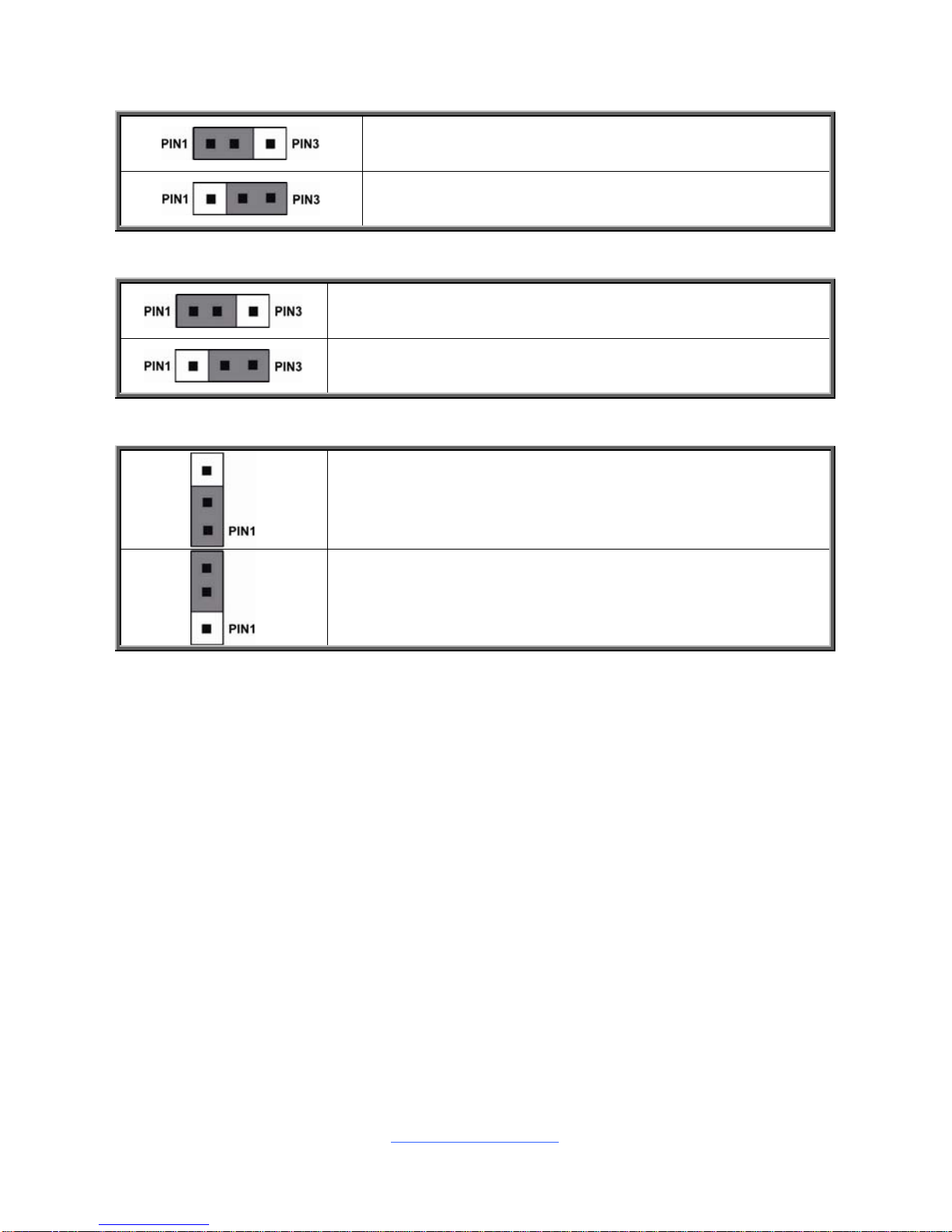
J42: Clear CMOS Jumper
Normal (Default)
Clear CMOS
You can reset the CMOS settings by using this jumper. This
can be useful if you have forgotten your system/setup
password, or need to clear the system BIOS setting.
1. Power off system and disconnect power connectors from
the motherboard.
2. Remove the jumper from Pin_1 and Pin_2 (Default setting).
3. Move the jumper cap to close Pin_2 and Pin_3 for several
seconds to Clear CMOS.
4. Put jumper cap back to Pin_1 and Pin_2 (Default setting).
5. Reconnect power connectors to the motherboard and
power on system.
http://www.tyan.com
23
J50
J59
J52
http://www.tyan.com
24
J50: ME Firmware Update Jumper
Pin 1-2 Closed: no function (Default)
Pin 2-3 Closed: Update ME Firmware
J52: BIOS Recovery Mode Jumper
Pin 1-2 Closed: Open (Default)
Pin 2-3 Closed: BIOS Recovery
J59: ME Recovery Mode Jumper
Pin 1-2 Closed: Open (Default)
Pin 2-3 Closed: ME Recovery
http://www.tyan.com
25
2.5 Installing the Processor and Heatsink
The types of processors supported by the S5530 are listed in the 1.2 Hardware
Specification section on page 5. Check our website at http://www.tyan.com
for
the latest list of validated Intel
®
processors for this specific motherboard.
NOTE: MiTAC is not liable for damage as a result of operating an
unsupported configuration.
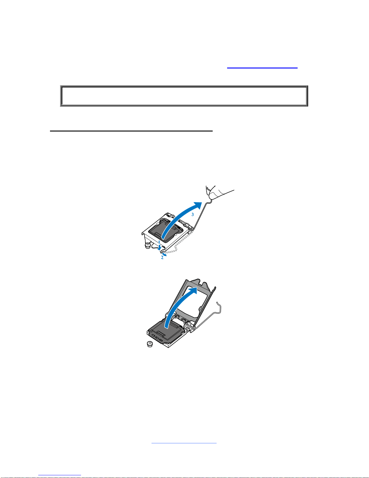
Processor Installation (Socket H3 for Intel CPU)
Follow the steps described later to install the processors and heat sinks.
NOTE: Please save and replace the CPU protection cap when returni ng for service.
1. Open the socket lever.
2. Open the CPU socket cover.
http://www.tyan.com
26
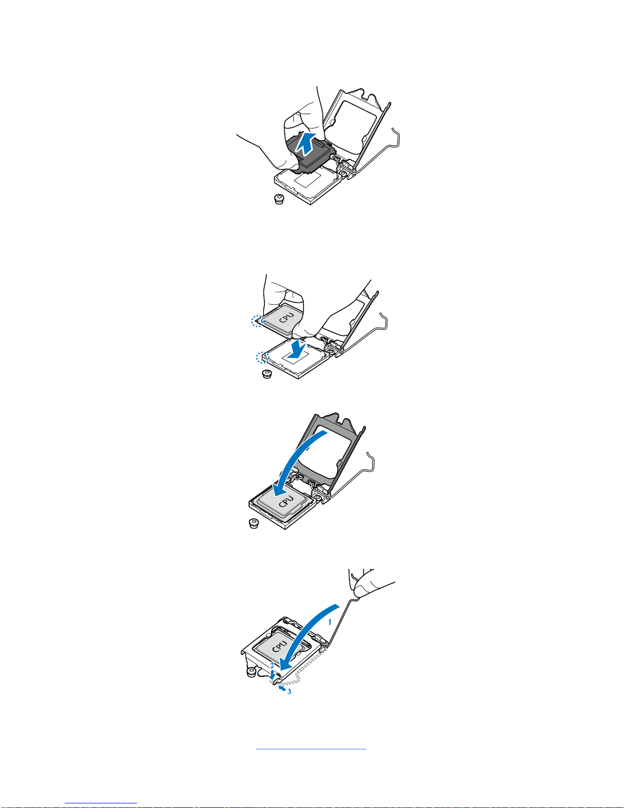
3. Remove the CPU protection cap.
4. Install the processor and make sure the gold arrow is located in the right
direction.
5. Close the CPU socket cover.
6. Close the socket lever.
http://www.tyan.com
27
Heat sink Installation
After installing the processor, you will need to proceed to install the heat sink. The
CPU heat sink will ensure that the processor do not overheat and continue to
operate at maximum performance for as long as you own them. An overheated
processor is dangerous to the motherboard. The processors will overheat within
seconds, enter thermal protection, and shut down if heatsinks are not installed.
For the safest method of installation and information on choosing the appropriate
heat sink, using heat sinks validated by Intel®. Please refer to the Intel® website:
http://www.intel.com
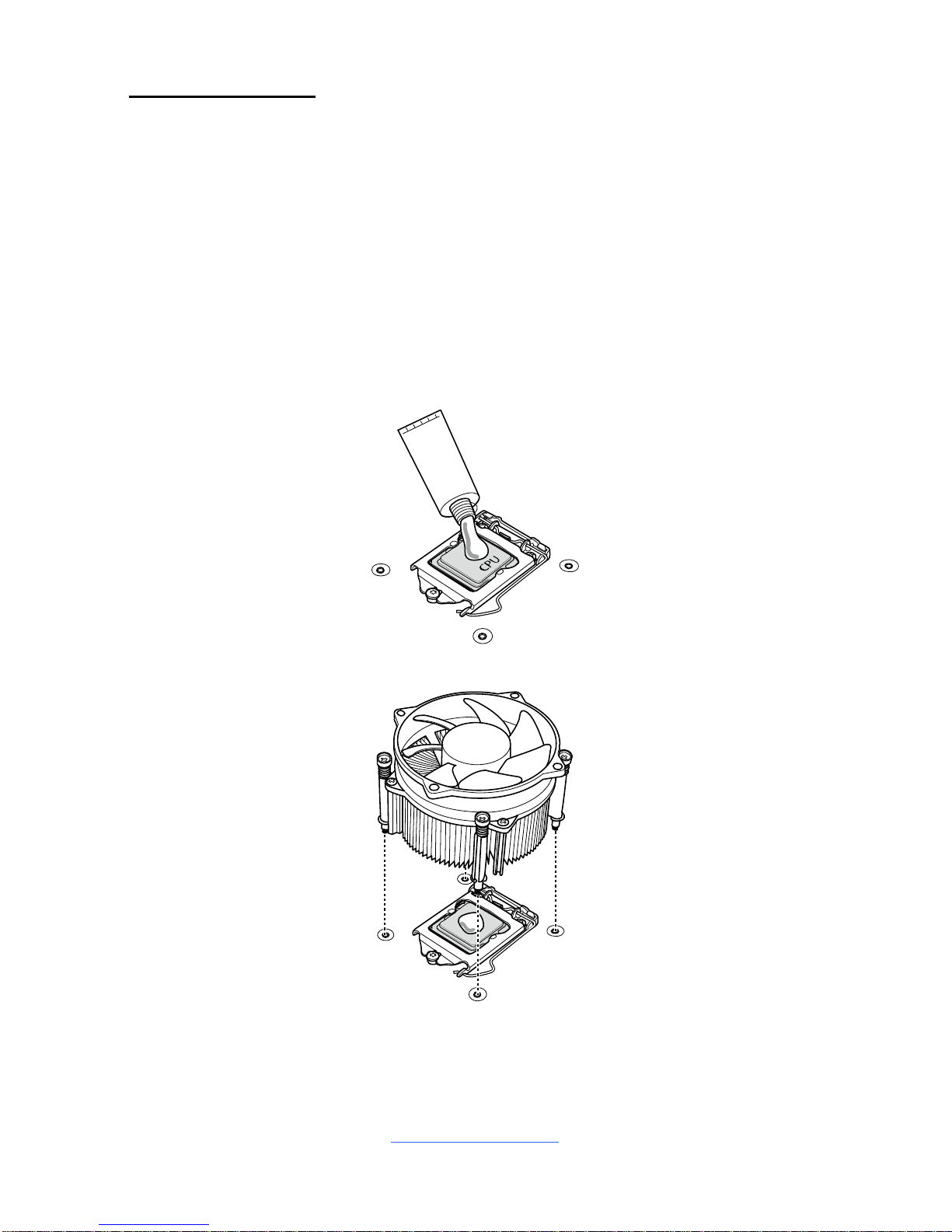
The following diagram illustrates how to install the heatsink on the Intel
®
H3 Socket:
1. Apply the thermal grease.
2. Install the CPU heatsink.
http://www.tyan.com
28
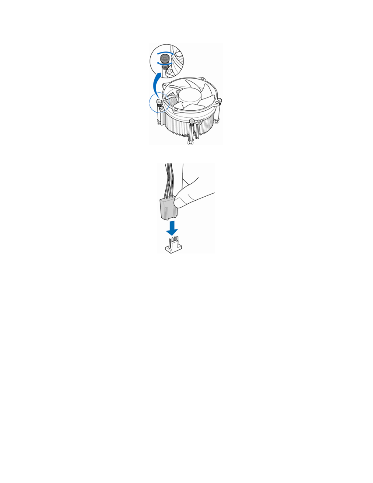
3. Secure the heatsink screws.
4. Connect the heatsink fan cable.
http://www.tyan.com
29
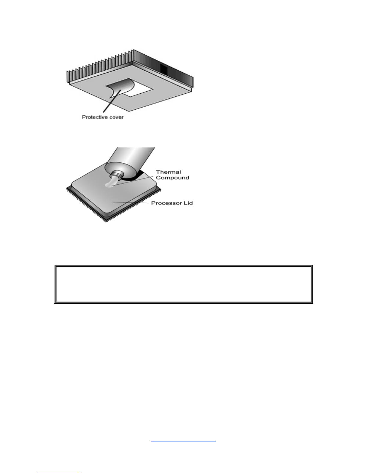
2.6 Thermal Interface Material
There are two types of
thermal interface materials
designed for use with the
processors.
The most common material
comes as a small pad
attached to the heat sink at
the time of purchase. There
should be a protective cover
over the material. Take care
not to touch this material.
Simply remove the protective
cover and place the heat
sink on the processor.
The second type of interface
material is usually packaged
separately. It is commonly
referred to as ‘thermal
compound’. Simply apply a
thin layer on to the CPU lid
(applying too much will
actually reduce the cooling).
NOTE: Always check with the manufacturer of the heat sink & processor to
ensure that the thermal interface material is compatible with the processor
and meets the manufacturer’s warranty requirements.
http://www.tyan.com
30
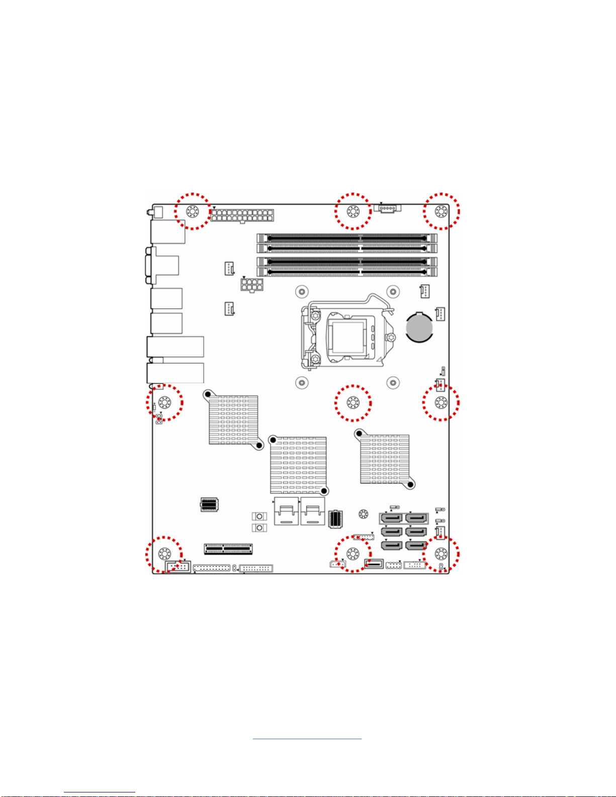
2.7 Tips on Installing Motherboard in Chassis
Before installing your motherboard, make sure your chassis has the necessary
motherboard support studs installed. These studs are usually metal and a re gold in
color. Usually, the chassis manufacturer will pre-install the support studs. If you ar e
unsure of stud placement, simply lay the motherb oard inside the chassis and align
the screw holes of the motherboard to the studs inside the case. If there are any
studs missing, you will know right away since the motherboard will not be able to b e
securely installed.
Note: Be especially careful to look for extra stand-offs. If there are any stand-offs
present that are not aligned with a mounting hole on the motherboard, it will likely
short components on the back of the motherboard when installed. This will cause
malfunction and/or damage to your motherboard.
 Loading...