

TYAN S5512 series User Manual

S5512
Version 1.1
Copyright
Copyright © MiTAC Computer Corporation, 2012. All rights reserved. No part of
this manual may be reproduced or translated without prior written consent from
MiTAC Computer Corp.
Trademark
All registered and unregistered trademarks and company names contained in
this manual are property of their respective owners including, but not limited to
the following.
TYAN® is a trademark of MiTAC Computer Corporation
Intel
®
is a trademark of Intel® Corporation.
AMI
®
, AMIBIOS® and combinations thereof are trademarks of AMI Technologies.
Microsoft
®
, Windows® are trademarks of Microsoft Corporation.
Aspeed
®
is a trademark of Aspeed Technology Inc.
Notice
Information contained in this document is furnished by MiTAC Computer
Corporation and has been reviewed for accuracy and reliability prior to printing.
MiTAC assumes no liability whatsoever, and disclaims any express or implied
warranty, relating to sale and/or use of TYAN
®
products including liability or
warranties relating to fitness for a particular purpose or merchantability. MiTAC
retains the right to make changes to product descriptions and/or specifications
at any time, without notice. In no event will MiTAC be held liable for any direct
or indirect, incidental or consequential damage, loss of use, loss of data or other
malady resulting from errors or inaccuracies of information contained in this
document.

http://www.TYAN.com
2
About this guide
This user guide contains the information you need when installing and configuring
the motherboard.
How this guide is organized
This guide contains the following parts:
Chapter1: Instruction
This chapter describes the features of the motherboard and the new technology it
supports.
Chapter2: Board Installation
This chapter lists the hardware setup procedures that you need to abide by when
installing system components. It includes description of the jumpers and connectors
on the motherboard.
Chapter3: BIOS Setup
This chapter tells how to change system settings through the BIOS setup menu.
Detailed descriptions of the BIOS parameters are also provided.
Chapter4: Diagnostics
This chapter introduces some BIOS codes and technical terms to provide better
service for the customers.
Appendix: Fan and Temp Sensors
This section aims to help readers identify the locations of some specific Fan and
Temp Sensors on the motherboard. A table of BIOS Temp sensor name
explanation is also included for readers’ reference.

http://www.TYAN.com
3
Contents
Before you begin…..............................................................................4
Chapter 1: Instruction..........................................................................5
1.1 - Congratulations .............................................................................................5
1.2 - Hardware Specifications................................................................................ 5
1.3 - Software Specifications ...............................................................................14
1.4 - AST2150 User Guide ..................................................................................14
Chapter 2: Board Installation............................................................15
2.1 - Board Image................................................................................................ 16
2.2 - Block Diagram ............................................................................................. 17
2.3 - Board Parts, Jumpers and Connectors........................................................ 18
2.4 - Installing the Processor ............................................................................... 33
2.5 - Installing the Heatsink ................................................................................. 36
2.6 - Thermal Interface Material........................................................................... 37
2.7 - Tips on Installing Motherboard in Chassis................................................... 38
2.8 - Installing the Memory .................................................................................. 40
2.9 - Attaching Drive Cables ................................................................................ 43
2.10 - Installing Add-In Cards .............................................................................. 44
2.11 - Connecting External Devices ....................................................................45
2.12 - Installing the Power Supply ....................................................................... 47
2.13 - Finishing Up .............................................................................................. 48
Chapter 3: BIOS Setup.......................................................................49
3.1 - About the BIOS............................................................................................ 49
3.2 - Setup Basics ............................................................................................... 49
3.3 - Getting Help ................................................................................................ 50
3.4 - In Case of Problems .................................................................................... 50
3.5 - BIOS Main Menu ......................................................................................... 51
3.6 - BIOS Advanced Menu................................................................................. 53
3.7 - Chipset Menu .............................................................................................. 84
3.8 - Boot Configuration....................................................................................... 92
3.9 - Security Menu.............................................................................................. 94
3.10 - Server Mgmt Menu .................................................................................... 95
3.10.1 - System Event Log Sub-Menu................................................................. 96
3.10.2 - BMC Network Configuration Sub-Menu.................................................. 97
3.11 - Event Logs ................................................................................................ 98
3.12 - Save & Exit Menu...................................................................................... 99
Chapter 4: Diagnostics....................................................................101
4.1 - Flash Utility................................................................................................ 101
4.2 - AMIBIOS Post Code (Aptio) ...................................................................... 102
Glossary............................................................................................113
Technical Support............................................................................119
http://www.TYAN.com
4
Before you begin…
Check the box contents!
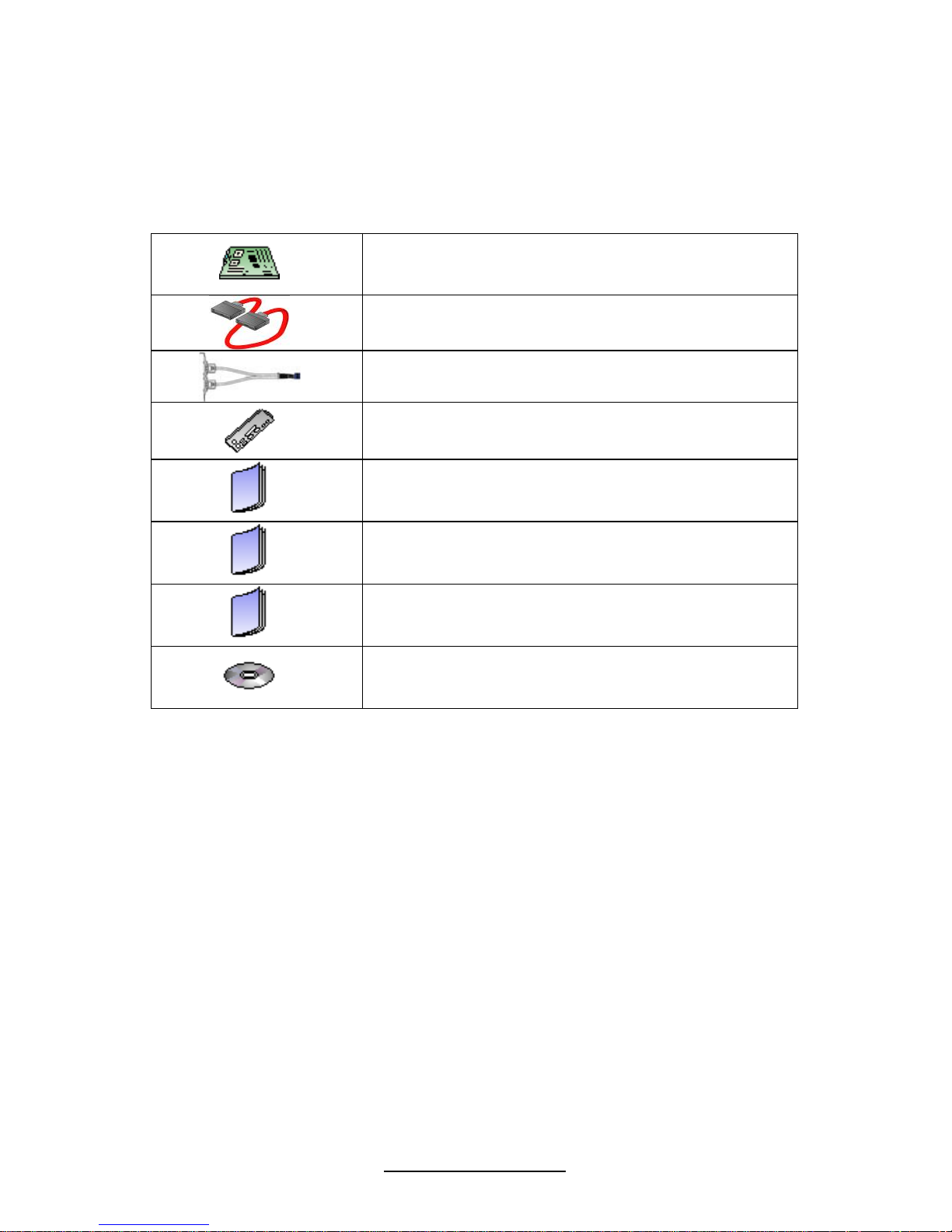
The retail motherboard package should contain the following:
1x S5512 Motherboard
6 x Serial ATA Cable or 8 x Serial ATA Cable
1 x USB2.0 Cable
1 x I/O shield
1 x I/O shield Installation Guide
1 x S5512 User’s manual
1 x S5512 Quick reference guide
1 x TYAN
®
Driver CD
If any of these items are missing, please contact your vendor/dealer for
replacement before continuing with the installation process.

http://www.TYAN.com
5
Chapter 1: Instruction
1.1 - Congratulations
You have purchased one of the most powerful server solutions. Based on the Intel
®
Cougar Point PCH chipset, the TYAN® S5512 series motherboard is designed to
support Single Intel
®
Xeon E3-1200 series, E3-1200 v2 series or Intel® 2nd Gen/3rd
Gen i3 series processor. It is up to 32GB Un-buffered DDR3 with ECC. The memory
interface supports speed up to 1600 MHz. There are also 2 channels with 4 DDR3
DIMMs, providing a rich feature set and incredible performance. Leveraging the
advanced technology from Intel
®
, the TYAN® S5512 series is capable of offering a
scalable 32 and 64-bit computing environment with high-bandwidth memory design
and lightning-fast PCI-E Gen2/3 bus implementation.
The S5512 not only empowers you in today’s demanding IT environment but also
offers a smooth path for future application upgradeability. All of these rich feature
sets provides the S5512 with the power and flexibility to meet demanding
requirements for today’s IT environments.
The TYAN S5512 series is designed around several different configurations which
are detailed in the following 1.2 Hardware Specification section:
1.2 - Hardware Specifications
TYAN S5512 (S5512GM2NR)
Supported CPU
Series
Intel Xeon E3-1200, i3-2100 (32nm / 22nm) series
processors
Socket Type / Q'ty LGA 1155/ (1)
Processor
Thermal Design
Power (TDP)
wattage
Max up to 95W
PCH Intel C204
Chipset
Super I/O Nuvoton 5577D
Supported DIMM
Qty
(4) DIMM slots
DIMM Type / Speed Unbuffered ECC DDR3 1600/1333
Capacity Up to 32GB
Memory channel 2 Channels
Memory
Memory voltage 1.5V
PCI-E
(1) PCI-E Gen.2 x8 slot (w/ x4 link) / (2) PCI-E Gen.2
x1 slots / (1) PCI-E Gen.3 x16 slot (w/ x8 link) / (1)
PCI-E x8 Gen.3 slot(w/ x8 link)
Note:
PCI-E Gen.2 x16 slot (w/ x8 link) can be x16 link for
customized purpose
Expansion
Slots
PCI (1) PCI 32-bit slot

http://www.TYAN.com
6
Port Q'ty (2)
LAN
Controller Intel 82574L
Connector (6) SATA
Controller Intel C204
Speed (2) 6.0 Gb/s (blue color), (4) 3.0 Gb/s (black color)
Storage SATA
RAID RAID 0/1/10/5 (Intel RST)
Connector type D-Sub 15-pin
Resolution Up to 1600x1200@60Hz
Graphic
Chipset Aspeed AST2150
USB
(10) USB2.0 ports (4 at rear, 4 via cable, 2 vertical
onboard)
COM (2) ports (1 at rear, 1 via cable)
VGA (1) D-Sub 15-pin VGA port
RJ-45 (2) GbE ports
Power SSI/ATX 24-pin + 8-pin power connectors
Front Panel (1) 2x12-pin SSI front panel header
Input /Output
SATA (4) SATA-II and (2) SATA-III connectors
Chipset Nuvoton 5577D
Voltage
Monitors voltage for CPU, memory, chipset & power
supply
Fan Total (5) 4-pin headers & (5)8-pin headers
Temperature Monitors temperature for CPU & system environment
LED
Fan fail LED indicator / Over temperature warning
indicator / Fan & PSU fail LED indicator
System
Monitoring
Others Chassis intrusion detection / Watchdog timer support
Onboard Chipset Onboard Aspeed AST2150
AST2150 IPMI
Feature
IPMI 2.0 compliant baseboard management controller
(BMC) / Supports storage over IP and remote platformflash / USB 2.0 virtual hub
Server
Management
AST2150 iKVM
Feature
24-bit high quality video compression / Dual 10/100
Mb/s MAC interfaces
Brand / ROM size 8MB / AMI
BIOS
Feature
Plug and Play (PnP) /PCI2.3 /WfM2.0 /SMBIOS2.3
/PXE boot / ACPI 2.0 power management /Power on
mode after power recovery / User-configurable H/W
monitoring / Auto-configurable of hard disk types
Form Factor ATX
Physical
Dimension
Board Dimension 12"x9.6" (305x243.8mm)
Operating
System
OS supported list Please refer to our OS supported list.
FCC (DoC) Class B
Regulation
CE (DoC) Yes
Operating Temp. 10° C ~ 35° C (50° F~ 95° F)
Operating
Environment
Non-operating
Temp.
- 40° C ~ 70° C (-40° F ~ 158° F)

http://www.TYAN.com
7
In/Non-operating
Humidity
90%, non-condensing at 35° C
RoHS RoHS 6/6 Compliant Yes
Motherboard (1) S5512 Motherboard
Manual (1) User's manual / (1) Quick Ref. Guide
Installation CD (1) TYAN installation CD
I/O Shield (1) I/O Shield
Package
Contains
Cable SATA (6) SATA signal cables
TYAN S5512 (S5512WGM2NR)
Supported CPU
Series
Intel Xeon E3-1200, i3-2100 (32nm / 22nm) series
processors
Socket Type / Q'ty LGA 1155/ (1)
Processor
Thermal Design
Power (TDP)
wattage
Max up to 95W
PCH Intel C204
Chipset
Super I/O Nuvoton 5577D
Supported DIMM
Qty
(4) DIMM slots
DIMM Type / Speed Unbuffered ECC DDR3 1600/1333
Capacity Up to 32GB
Memory channel 2 Channels
Memory
Memory voltage 1.5V
PCI-E
(2) PCI-E Gen.2 x1 slots / (1) PCI-E Gen.3 x16 slot (w/
x8 link) / (1) PCI-E x8 Gen.3 slot(w/ x8 link)
Note:
PCI-E Gen.2 x16 slot (w/ x8 link) can be x16 link for
customized purpose
Expansion
Slots
PCI (1) PCI 32-bit slot
Port Q'ty (2)
LAN
Controller Intel 82574L
Connector (8) SAS
Controller LSI SAS2008
Speed 6.0 Gb/s
SAS
RAID RAID 0/1/1E/10 (LSI Integrated RAID)
Connector (6) SATA
Controller Intel C204
Speed (2) 6.0 Gb/s (blue color), (4) 3.0 Gb/s (black color)
Storage
SATA
RAID RAID 0/1/10/5 (Intel RST)
Connector type D-Sub 15-pin
Resolution Up to 1600x1200@60Hz
Graphic
Chipset Aspeed AST2150

http://www.TYAN.com
8
USB
(10) USB2.0 ports (4 at rear, 4 via cable, 2 vertical
onboard)
COM (2) ports (1 at rear, 1 via cable)
VGA (1) D-Sub 15-pin VGA port
RJ-45 (2) GbE ports
Power SSI/ATX 24-pin + 8-pin power connectors
Front Panel (1) 2x12-pin SSI front panel header
Input /Output
SATA (4) SATA-II and (2) SATA-III connectors
Chipset Nuvoton 5577D
Voltage
Monitors voltage for CPU, memory, chipset & power
supply
Fan Total (5) 4-pin headers & (5)8-pin headers
Temperature Monitors temperature for CPU & system environment
LED
Fan fail LED indicator / Over temperature warning
indicator / Fan & PSU fail LED indicator
System
Monitoring
Others Chassis intrusion detection / Watchdog timer support
Onboard Chipset Onboard Aspeed AST2150
AST2150 IPMI
Feature
IPMI 2.0 compliant baseboard management controller
(BMC) / Supports storage over IP and remote
platform-flash / USB 2.0 virtual hub
Server
Management
AST2150 iKVM
Feature
24-bit high quality video compression / Dual 10/100
Mb/s MAC interfaces
Brand / ROM size 8MB / AMI
BIOS
Feature
Plug and Play (PnP) /PCI2.3 /WfM2.0 /SMBIOS2.3
/PXE boot / ACPI 2.0 power management /Power on
mode after power recovery / User-configurable H/W
monitoring / Auto-configurable of hard disk types
Form Factor ATX
Physical
Dimension
Board Dimension 12"x9.6" (305x243.8mm)
Operating
System
OS supported list Please refer to our OS supported list.
FCC (DoC) Class B
Regulation
CE (DoC) Yes
Operating Temp. 10° C ~ 35° C (50° F~ 95° F)
Non-operating
Temp.
- 40° C ~ 70° C (-40° F ~ 158° F)
Operating
Environment
In/Non-operating
Humidity
90%, non-condensing at 35° C
RoHS RoHS 6/6 Compliant Yes
Motherboard (1) S5512 Motherboard
Manual (1) User's manual / (1) Quick Ref. Guide
Installation CD (1) TYAN installation CD
I/O Shield (1) I/O Shield
Package
Contains
Cable SAS/SATA (8) SAS/SATA signal cables

http://www.TYAN.com
9
TYAN S5512 (S5512GM4NR)
Supported CPU
Series
Intel Xeon E3-1200, i3-2100 (32nm / 22nm) series
processors
Socket Type / Q'ty LGA 1155/ (1)
Processor
Thermal Design
Power (TDP)
wattage
Max up to 95W
PCH Intel C204
Chipset
Super I/O Nuvoton 5577D
Supported DIMM
Qty
(4) DIMM slots
DIMM Type / Speed Unbuffered ECC DDR3 1600/1333
Capacity Up to 32GB
Memory channel 2 Channels
Memory
Memory voltage 1.5V
PCI-E
(1) PCI-E Gen.2 x8 slot (w/ x4 link) / (2) PCI-E Gen.2
x1 slots / (1) PCI-E Gen.3 x16 slot (w/ x8 link) / (1)
PCI-E x8 Gen.3 slot(w/ x8 link)
Note:
PCI-E Gen.2 x16 slot (w/ x8 link) can be x16 link for
customized purpose
Expansion
Slots
PCI (2) PCI 32-bit slots
Port Q'ty (4)
LAN
Controller Intel 82574L
Connector (6) SATA
Controller Intel C204
Speed (2) 6.0 Gb/s (blue color), (4) 3.0 Gb/s (black color)
Storage SATA
RAID RAID 0/1/10/5 (Intel RST)
Connector type D-Sub 15-pin
Resolution Up to 1600x1200@60Hz
Graphic
Chipset Aspeed AST2150
USB
(10) USB2.0 ports (4 at rear, 4 via cable, 2 vertical
onboard)
COM (2) ports (1 at rear, 1 via cable)
VGA (1) D-Sub 15-pin VGA port
RJ-45 (4) GbE ports
Power SSI/ATX 24-pin + 8-pin power connectors
Front Panel (1) 2x12-pin SSI front panel header
Input /Output
SATA (4) SATA-II and (2) SATA-III connectors
Chipset Nuvoton 5577D
Voltage
Monitors voltage for CPU, memory, chipset & power
supply
Fan Total (5) 4-pin headers & (5)8-pin headers
Temperature Monitors temperature for CPU & system environment
System
Monitoring

http://www.TYAN.com
10
LED
Fan fail LED indicator / Over temperature warning
indicator / Fan & PSU fail LED indicator
Others Chassis intrusion detection / Watchdog timer support
Onboard Chipset Onboard Aspeed AST2150
AST2150 IPMI
Feature
IPMI 2.0 compliant baseboard management controller
(BMC) / Supports storage over IP and remote platformflash / USB 2.0 virtual hub
Server
Management
AST2150 iKVM
Feature
24-bit high quality video compression / Dual 10/100
Mb/s MAC interfaces
Brand / ROM size 8MB / AMI
BIOS
Feature
Plug and Play (PnP) /PCI2.3 /WfM2.0 /SMBIOS2.3
/PXE boot / ACPI 2.0 power management /Power on
mode after power recovery / User-configurable H/W
monitoring / Auto-configurable of hard disk types
Form Factor ATX
Physical
Dimension
Board Dimension 12"x9.6" (305x243.8mm)
Operating
System
OS supported list Please refer to our OS supported list.
FCC (DoC) Class B
Regulation
CE (DoC) Yes
Operating Temp. 10° C ~ 35° C (50° F~ 95° F)
Non-operating
Temp.
- 40° C ~ 70° C (-40° F ~ 158° F)
Operating
Environment
In/Non-operating
Humidity
90%, non-condensing at 35° C
RoHS RoHS 6/6 Compliant Yes
Motherboard (1) S5512 Motherboard
Manual (1) User's manual / (1) Quick Ref. Guide
Installation CD (1) TYAN installation CD
I/O Shield (1) I/O Shield
Package
Contains
Cable SATA (6) SATA signal cables
TYAN S5512-HE (S5512G2NR-HE)
Supported CPU
Series
Intel Xeon E3-1200, i3-2100 (32nm / 22nm) series
processors
Socket Type / Q'ty LGA 1155/ (1)
Processor
Thermal Design
Power (TDP)
wattage
Max up to 95W
PCH Intel C206
Chipset
Super I/O Nuvoton 5577D
Supported DIMM
Qty
(4) DIMM slots
Memory
DIMM Type / Speed Unbuffered ECC DDR3 1600/1333

http://www.TYAN.com
11
Capacity Up to 32GB
Memory channel 2 Channels
Memory voltage 1.5V
PCI-E
(1) PCI-E Gen.2 x8 slot (w/ x4 link) / (2) PCI-E Gen.2
x1 slots / (1) PCI-E Gen.3 x16 slot (w/ x8 link) / (1)
PCI-E x8 Gen.3 slot(w/ x8 link)
Note: use Intel Ivy Bridge CPU to support PCI-E Gen.3
Expansion
Slots
PCI (1) PCI 32-bit slot
Port Q'ty (2)
LAN
Controller Intel 82574L
Connector (6) SATA
Controller Intel C206
Speed (2) 6.0 Gb/s (blue color), (4) 3.0 Gb/s (black color)
Storage SATA
RAID RAID 0/1/10/5 (Intel RST)
Connector type D-Sub 15-pin
Resolution Up to 1600x1200@60Hz
Graphic
Chipset Aspeed AST2150-GP-V
USB
(9) USB2.0 ports (4 at rear, 4 via cable, 1 type A
onboard)
COM (1) port (rear)
VGA (1) D-Sub 15-pin VGA port
RJ-45 (2) GbE ports
Power SSI/ATX 24-pin + 8-pin power connectors
Front Panel (1) 2x12-pin SSI front panel header
Input /Output
SATA (4) SATA-II and (2) SATA-III connectors
Chipset Nuvoton 5577D
Voltage
Monitors voltage for CPU, memory, chipset & power
supply
Fan Total (5) 4-pin headers & (5)8-pin headers
Temperature Monitors temperature for CPU & system environment
LED
Fan fail LED indicator / Over temperature warning
indicator / Fan & PSU fail LED indicator
System
Monitoring
Others Chassis intrusion detection / Watchdog timer support
Brand / ROM size 8MB / AMI
BIOS
Feature
Plug and Play (PnP) /PCI2.3 /WfM2.0 /SMBIOS2.3
/PXE boot / ACPI 2.0 power management /Power on
mode after power recovery / User-configurable H/W
monitoring / Auto-configurable of hard disk types
Form Factor ATX
Physical
Dimension
Board Dimension 12"x9.6" (305x243.8mm)
Operating
System
OS supported list Please refer to our OS supported list.
FCC (DoC) Class B
Regulation
CE (DoC) Yes

http://www.TYAN.com
12
Operating Temp. 0° C ~ 55° C (32° F~ 131° F)
Non-operating
Temp.
- 40° C ~ 70° C (-40° F ~ 158° F)
Operating
Environment
In/Non-operating
Humidity
90%, non-condensing at 35° C
RoHS RoHS 6/6 Compliant Yes
Motherboard (1) S5512 Motherboard
Manual (1) User's manual / (1) Quick Ref. Guide
Installation CD (1) TYAN installation CD
I/O Shield (1) I/O Shield
Package
Contains
Cable SATA (6) SATA signal cables
TYAN S5512-LE (S5512G2NR-LE)
Supported CPU
Series
Intel Xeon E3-1200, i3-2100 (32nm / 22nm) series
processors
Socket Type / Q'ty LGA 1155/ (1)
Processor
Thermal Design
Power (TDP)
wattage
Max up to 95W
PCH Intel C202
Chipset
Super I/O Nuvoton 5577D
Supported DIMM
Qty
(4) DIMM slots
DIMM Type / Speed Unbuffered ECC DDR3 1600/1333
Capacity Up to 32GB
Memory channel 2 Channels
Memory
Memory voltage 1.5V
PCI-E
(2) PCI-E Gen.2 x1 slots / (1) PCI-E Gen.3 x16 slot (w/
x8 link) / (1) PCI-E x8 Gen.3 slot(w/ x8 link)
Note: use Intel Ivy Bridge to support PCI-E Gen.3
Expansion
Slots
PCI (1) PCI 32-bit slot
Port Q'ty (2)
LAN
Controller Intel 82574L
Connector (6) SATA
Controller Intel C202
Speed 3.0 Gb/s
Storage SATA
RAID RAID 0/1/10/5 (Intel RST)
Connector type D-Sub 15-pin
Resolution Up to 1600x1200@60Hz
Graphic
Chipset Aspeed AST2150-GP-V

http://www.TYAN.com
13
USB (8) USB2.0 ports (4 at rear, 4 via cable)
COM (1) port (rear)
VGA (1) D-Sub 15-pin VGA port
RJ-45 (2) GbE ports
Power SSI/ATX 24-pin + 8-pin power connectors
Front Panel (1) 2x12-pin SSI front panel header
Input /Output
SATA (6) SATA-II connectors
Chipset Nuvoton 5577D
Voltage
Monitors voltage for CPU, memory, chipset & power
supply
Fan Total (5) 4-pin headers
Temperature Monitors temperature for CPU & system environment
LED
Fan fail LED indicator / Over temperature warning
indicator / Fan & PSU fail LED indicator
System
Monitoring
Others Chassis intrusion detection / Watchdog timer support
Brand / ROM size 8MB / AMI
BIOS
Feature
Plug and Play (PnP) /PCI2.3 /WfM2.0 /SMBIOS2.3
/PXE boot / ACPI 2.0 power management /Power on
mode after power recovery / User-configurable H/W
monitoring / Auto-configurable of hard disk types
Form Factor ATX
Physical
Dimension
Board Dimension 12"x9.6" (305x243.8mm)
Operating
System
OS supported list Please refer to our OS supported list.
FCC (DoC) Class B
Regulation
CE (DoC) Yes
Operating Temp. 10° C ~ 35° C (50° F~ 95° F)
Non-operating
Temp.
- 40° C ~ 70° C (-40° F ~ 158° F)
Operating
Environment
In/Non-operating
Humidity
90%, non-condensing at 35° C
RoHS RoHS 6/6 Compliant Yes
Motherboard (1) S5512 Motherboard
Manual (1) User's manual / (1) Quick Ref. Guide
Installation CD (1) TYAN installation CD
I/O Shield (1) I/O Shield
Package
Contains
Cable SATA (6) SATA signal cables

http://www.TYAN.com
14
S5512 SKU Comparison Table
Cougar
Point
Expand.
slot
PartNumber BMC
PCH
X16/X8
/X1/PCI
SAS
6Gb/s
SATA
6Gb/s
SATA
3Gb/s
LAN
port
IPMI
port
S5512GM2NR
Yes
Standard
(C204)
1 / 2 /
2 / 1
No 2 4 2 1
S5512GM4NR
Yes
Standard
(C204)
1 / 2 /
2 / 1
No 2 4 4 1
S5512WGM2NR
Yes
Standard
(C204)
1 / 1 /
2 / 1
Yes 2 4 2 1
S5512G2NR‐LE
No
Essential
(C202)
1 / 1 /
2 / 1
No 0 6 2 0
S5512G2NR‐HE(BTO)
No
Advance
(C206)
1 / 2 /
2 / 1
No 2 4 2 0
1.3 - Software Specifications
For OS (operation system) support, please check the TYAN® website for the latest
information.
1.4 - AST2150 User Guide
Remember to visit TYAN®’s Website at http://www.TYAN.com for AST2150
updated user guide.
http://www.TYAN.com
15
Chapter 2: Board Installation
You are now ready to install your motherboard.
How to install our products right… the first time
The first thing you should do is reading this user’s manual. It contains important
information that will make configuration and setup much easier. Here are some
precautions you should take when installing your motherboard:
(1) Ground yourself properly before removing your motherboard from the
antistatic bag. Unplug the power from your computer power supply and
then touch a safely grounded object to release static charge (i.e. power
supply case). For the safest conditions, TYAN
®
recommends wearing a
static safety wrist strap.
(2) Hold the motherboard by its edges and do not touch the bottom of the
board, or flex the board in any way.
(3) Avoid touching the motherboard components, IC chips, connectors,
memory modules, and leads.
(4) Place the motherboard on a grounded antistatic surface or on the antistatic
bag that the board was shipped in.
(5) Inspect the board for damage.
The following pages include details on how to install your motherboard into your
chassis, as well as installing the processor, memory, disk drives and cables.
DO NOT apply power to the board if it has been damaged.
http://www.TYAN.com
16
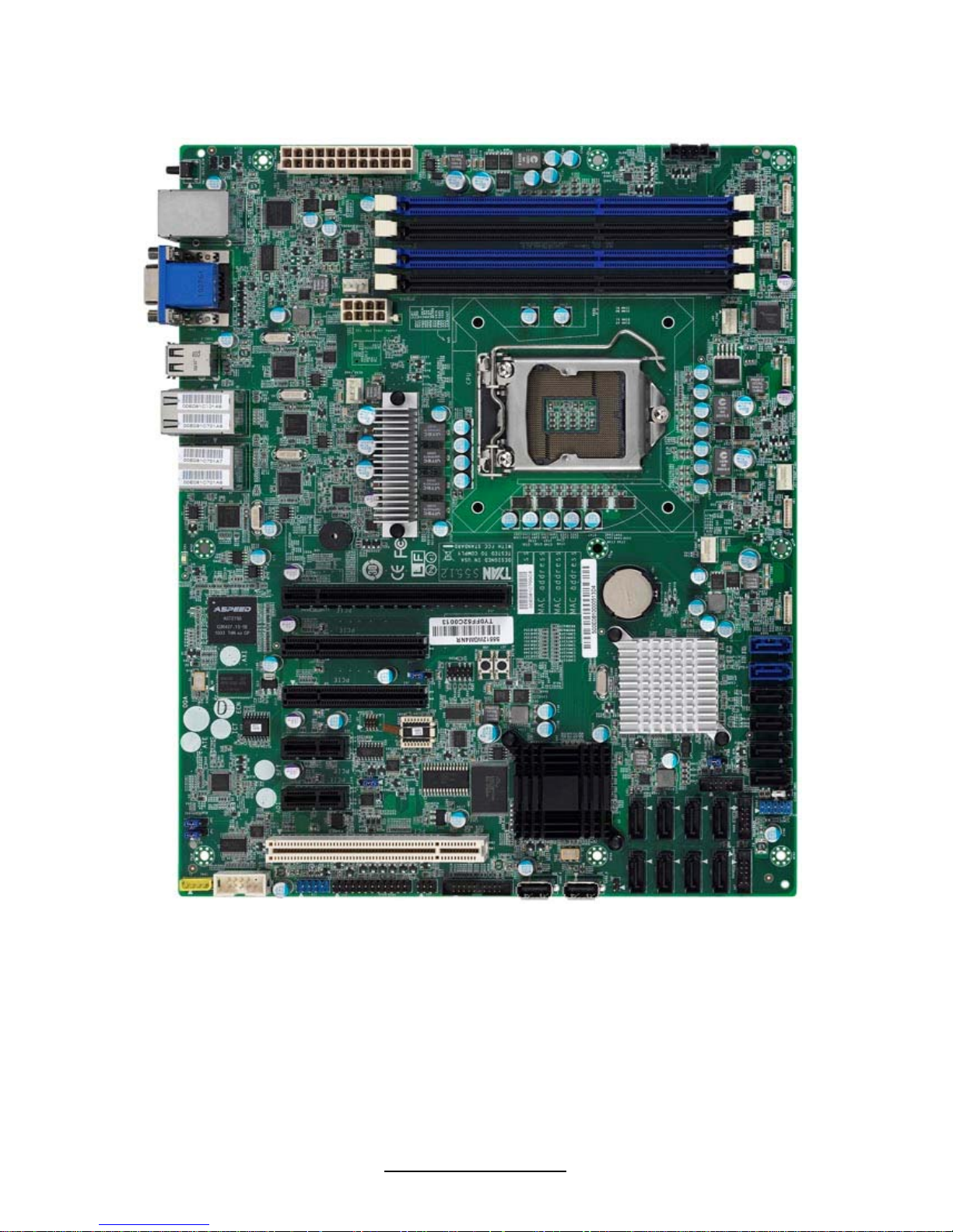
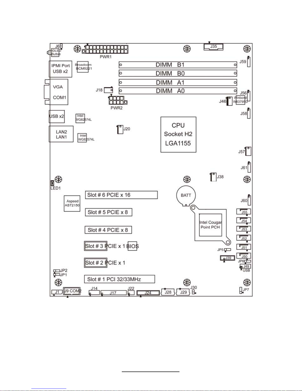
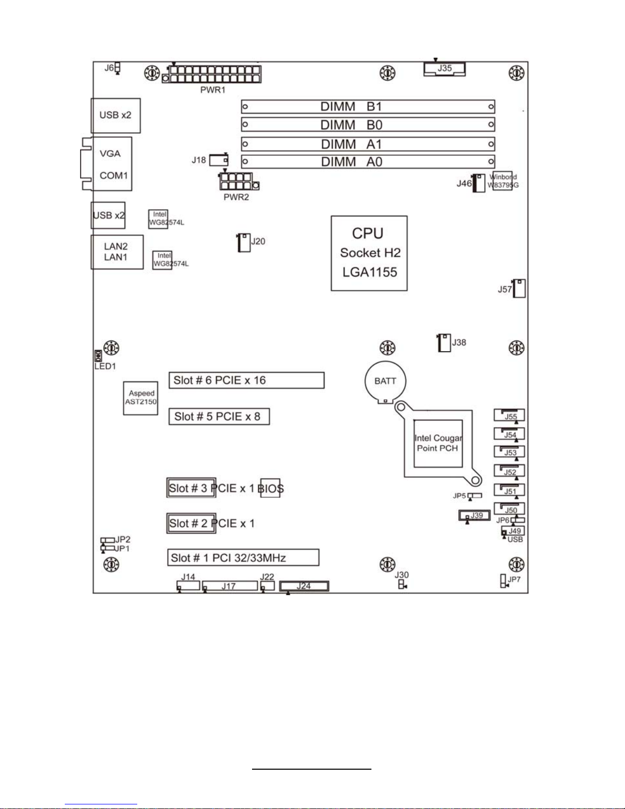
2.1 - Board Image
S5512
This diagram is representative of the latest motherboard revision available at the
time of publishing. The board you receive may not look exactly like the above
diagram.
http://www.TYAN.com
17
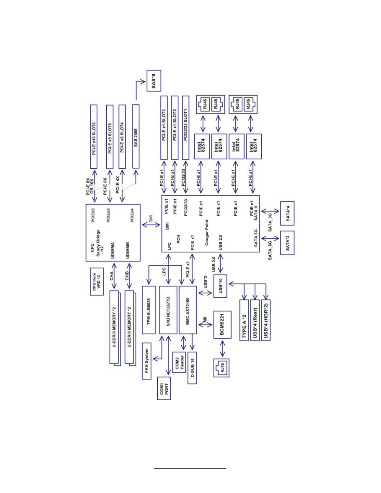
2.2 - Block Diagram
S5512 Block Diagram

http://www.TYAN.com
18
2.3 - Board Parts, Jumpers and Connectors
S5512 SKU Comparison Table II
S5512 series jumper and connector Support SKUs
Jumper/Connector Function
GM
2NRGM4NR
WGM
2NR
G2NR-HE G2NR-LE
J18/J20/J38/J46/J57 4-Pin Fan Connectors
YES YES YES YES YES
J56/J58/J59/J60/J61 8-Pin Fan Connectors
YES YES YES YES NO
SW1 ID LED Switch Button
YES YES YES NO NO
J1 IPMB Connector
YES YES YES NO NO
J6
Front Panel IDLED
Switch 2Pin Header
YES YES YES YES YES
J9 COM2 Header
YES YES YES NO NO
J14/J49
Dual USB2.0 Header
YES YES YES YES YES
J17
Front Panel Header
YES YES YES YES YES
J22
LAN ACTIVE LED
Header
YES YES YES YES YES
J24
Fan Front Header
YES YES YES YES YES
J28
USB 2.0 Type-A
Connector
YES YES YES NO NO
J29
USB 2.0 Type-A
Connector
YES YES YES YES NO
J30
Intrusion Switch 2Pin
Headers
YES YES YES YES YES
J35
PSMI Connector
YES YES YES YES YES
J39
SGPIO Header
YES YES YES YES YES
J47/J48
SGPIO Header
NO NO YES NO NO
J31/J32/J33/J34
SAS(Port7/Port3/
Port6/Port2)
NO NO YES NO NO
J36/J37/J40/J41
SAS (Port5/Port1/
Port4/Port0)
NO NO YES NO NO
JP5
ME recovery function
set
YES YES YES YES YES
JP6
RTC Clear CMOS set
YES YES YES YES YES
JP7
ME update function set
YES YES YES YES YES
http://www.TYAN.com
19
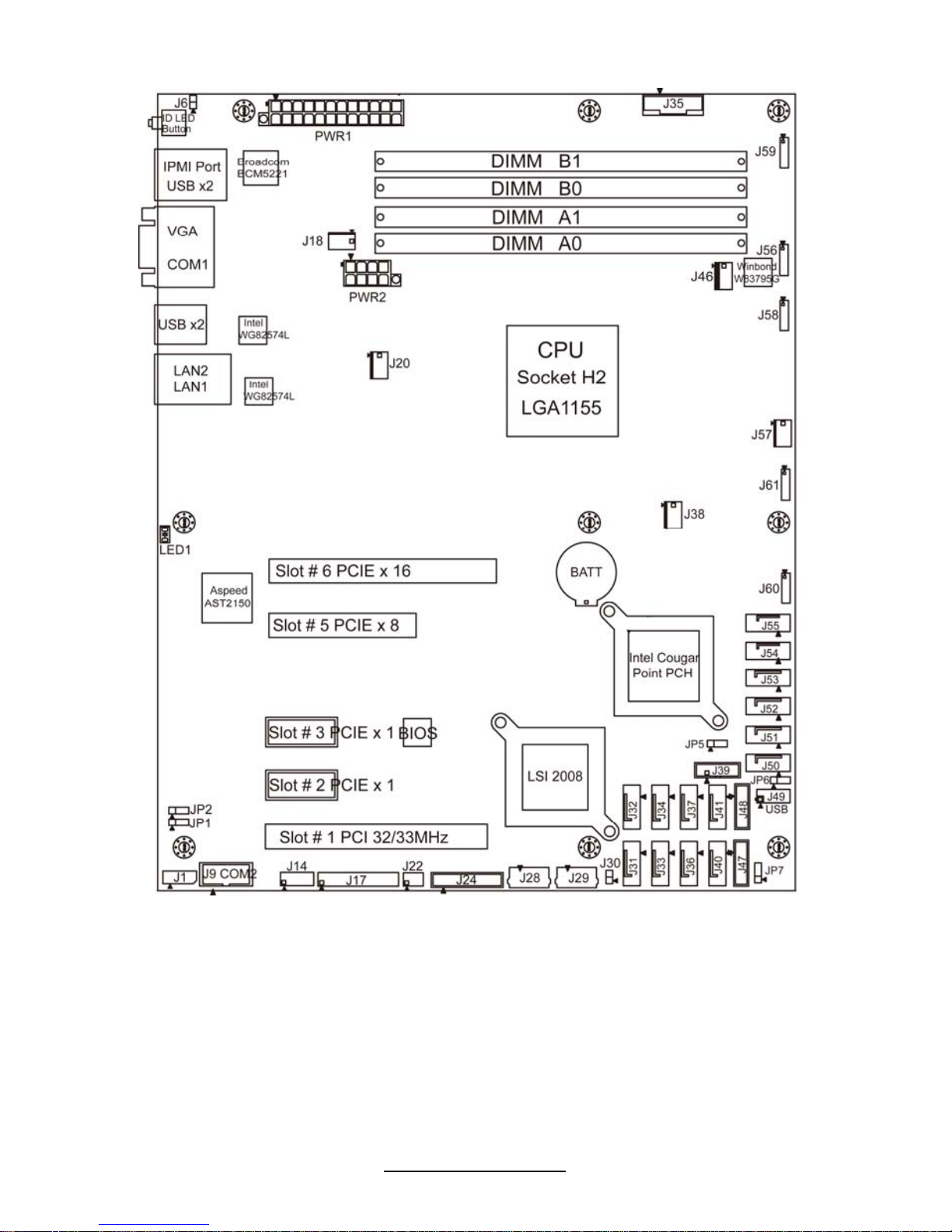
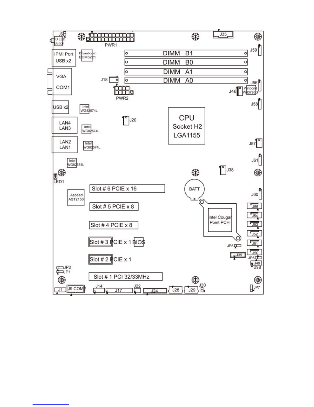
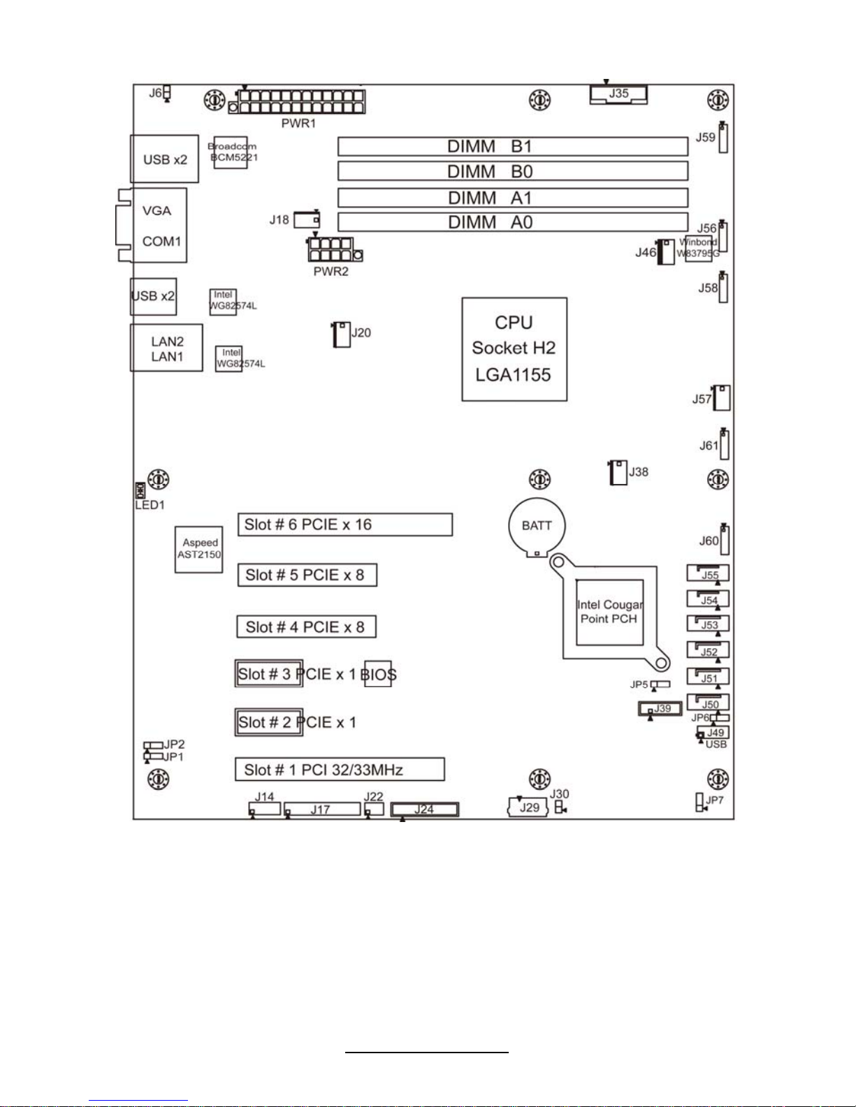
NOTE: ▲in the image indicates pin 1. There are five SKUs of S5512 motherboard.
S5512GM2NR
http://www.TYAN.com
20
S5512WGM2NR
http://www.TYAN.com
21
S5512GM4NR
http://www.TYAN.com
22
S5512G2NR-HE
http://www.TYAN.com
23
S5512G2NR-LE
http://www.TYAN.com
24
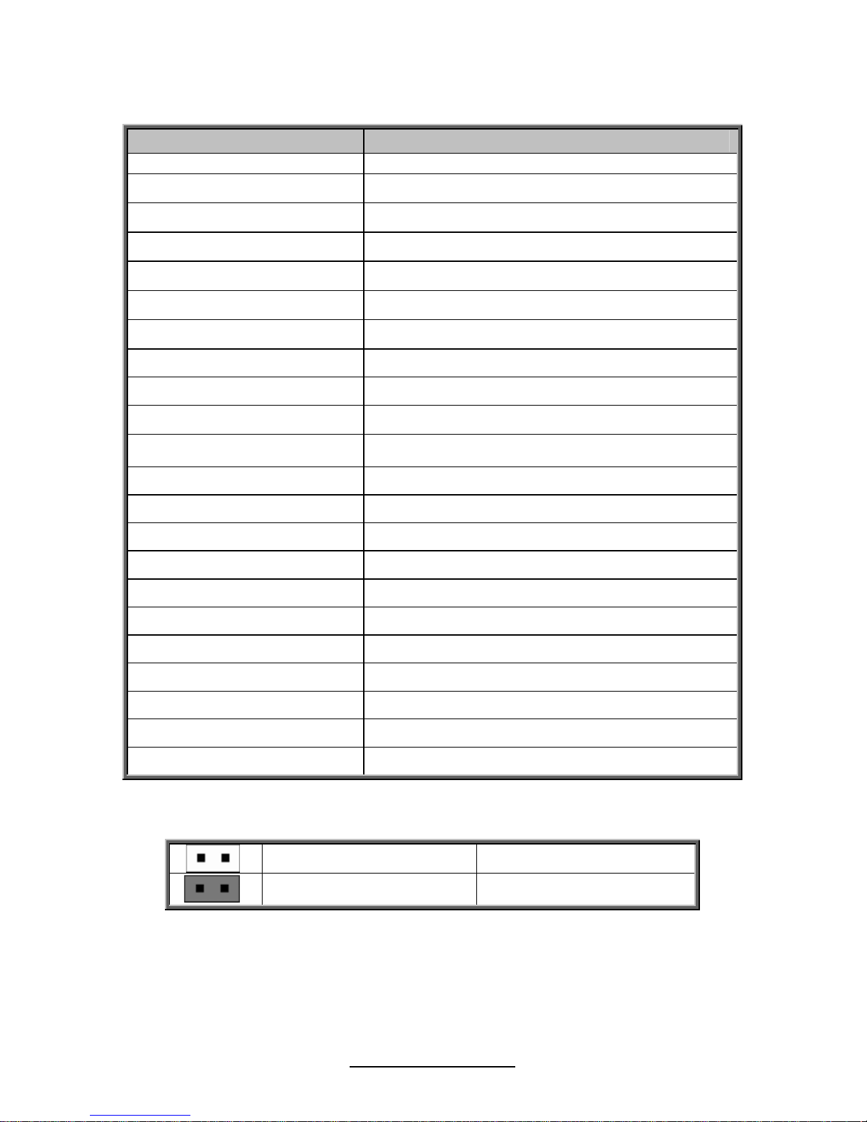
Jumpers & Connectors
Jumper/Connector Function
J56/J58/J59/J60/J61 8-Pin Fan Header (For Barebone)
J18/J20/J38/J46/J57 4-Pin Fan Connector
J1 IPMB Connector
J6 Front Panel IDLED Switch 2 Pin Header
J9 COM2 Header
J14/J49 Dual USB2.0 Header
J17 Front Panel Header
J22 LAN ACTIVE LED Header
J24 Fan Front Header
J28 USB 2.0 Type-A Connector
J29 USB 2.0 Type-A Connector
J30 Intrusion Switch 2Pin Headers
J35 PSMI Connector
J39 SGPIO Header
J47/J48 SGPIO Header
J31/J32/J33/J34 SAS (Port7/Port3/Port6/Port2)
J36/J37/J40/J41 SAS (Port5/Port1/Port4/Port0)
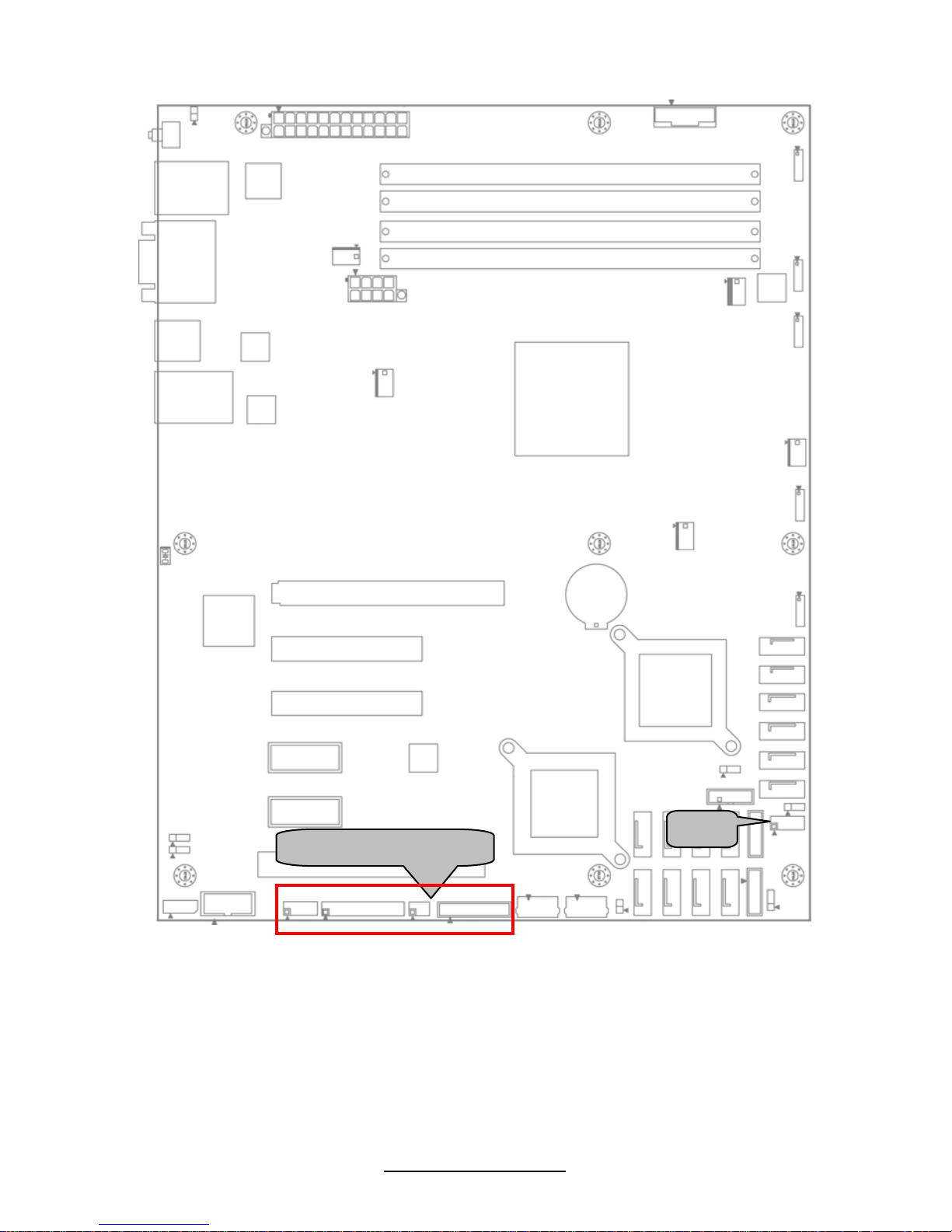
J50/J51/J52/J53 SATA2.0 (Port5/Port4/Port3/Port2)
J54/J55 SATA3.0 (Port1/Port0)
JP5 ME recovery function set
JP6 RTC Clear CMOS set
JP7 ME update function set
Jumper Legend
OPEN - Jumper OFF
Without jumper cover
CLOSED - Jumper ON
With jumper cover

http://www.TYAN.com
25
Jumper Placement
J56
J61
J57
J59
J20
J18
J58
J38
J60
J46
J1
J6
J9
http://www.TYAN.com
26
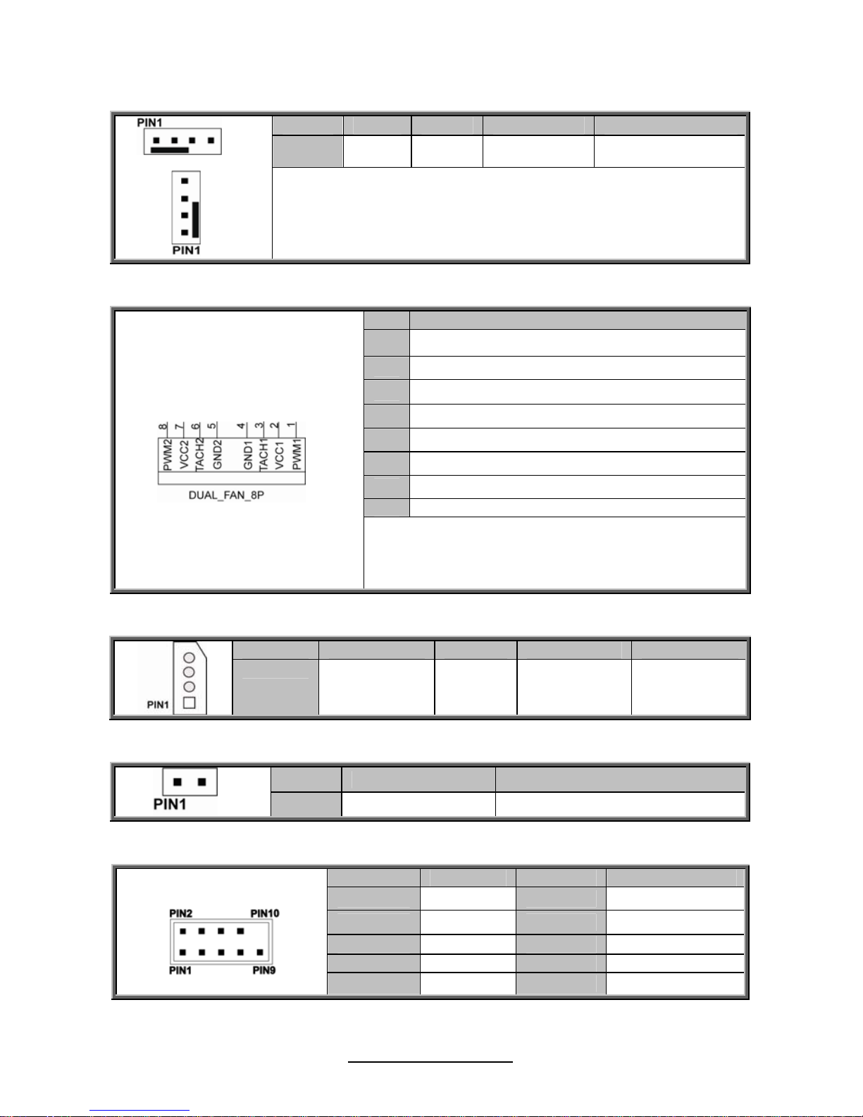
J18/J20/J38/J46/J57: 4-Pin FAN Connector
Pin 1 2 3 4
Signal GND VCC Tachometer PWM
NOTE:
Use this header to connect the cooling fan to your motherboard to
keep the system stable and reliable.
J56/J58/J59/J60/J61: 8-Pin FAN Connector
Pin Signal
1
PWM1
2
VCC1
3
Tachometer1
4
GND1
5
GND2
6
Tachometer2
7
VCC2
8
PWM2
NOTE:
Do not mix 8-pin Fan headers with 4-pin Fan headers.
Mixing these fan headers will cause problems to the
system. These connectors are only for the barebone.
J1: IPMB Connector
Pin 1 2 3 4
Signal
IPMB DATA GND IPMB CLK NC
J6: Front Panel IDLED Switch2 Pin Header
Pin 1 2
Signal
FP IDLED Switch FP IDLED Switch (GND)
J9: COM2 Header
Pin Signal Pin Signal
1 DCD 2 DSR
3
RXD
4
RTS
5
TXD
6
CTS
7 DTR 8 RI
9
GND
10
KEY
http://www.TYAN.com
27
J14/J17/J22/J24
J49

http://www.TYAN.com
28
J14:Dual USB2.0 Header (Port4/Port5)/J49:Dual USB2.0 Header
(Port2/Port3)
Pin Signal Pin Signal
1 USB 5V Power 2 USB 5V Power
3 USB Data- 4 USB Data-
5 USB Data+ 6 USB Data+
7 GND 8 GND
9 KEY 10 NC
J17: Front Panel Header
Pin Signal Pin Signal
1 PWRLED+ 2 FP Power (3.3V)
3
KEY
4
ID_LED+
5 PWRLED-(GND) 6 ID_LED-(GND)
7 HD_LED+ 8 Fault LED1-
9 HD_LED- 10 Fault LED2-
11 Power Switch+ 12 LAN1_ACTIVE_LED+
13 GND 14 LAN1_ACTIVE_LED-
15 Reset Switch+ 16 SMB_DATA
17 GND 18 SMB_CLK
19 ID Switch+ 20 INTRUSION#
21 TBMP Sensor 22 LAN2_ACTIVE_LED+
23
NMI Switch#
24
LAN2_ACTIVE_LED-
J22: LAN ACTIVE LED Header
Pin Signal
1 LAN3_ACTIVE_LED +
2 LAN3_ACTIVE_LED-(GND)
J24: FAN Front Header
Pin Signal Pin Signal
1 SYSFAN_TACH1 2 SYSFAN_TACH6
3
SYSFAN_TACH2
4
SYSFAN_TACH7
5
SYSFAN_TACH3
6
SYSFAN_TACH8
7
SYSFAN_TACH4
8
SYSFAN_TACH9
9
SYSFAN_TACH5
10
SYSFAN_TACH10
11 GND 12 KEY
13
SYSFAN_PWM5
14
SYSFAN_PWM4
15 NC 16 SMB_FRU_SDA
17 NC 18 SMB_FRU_SCL
19 V3AUX 20 SYSFAN_PWM6

http://www.TYAN.com
29
J39
J28 J29
J30
J35
http://www.TYAN.com
30
J28/J29:USB 2.0 Type-A Connector
Pin 1 2 3 4
Signal USB 5V power USB Data- USB Data+ GND
J30: Intrusion Switch 2Pin Header
Pin Signal
1 INTRUSION switch
2 INTRUSION switch(GND)
J35: PSMI Connector
Pin 1 2 3 4 5
Signal
PSMI
Clock
PSMI
Data
PSU
Alert#
GND
3.3V
Standby
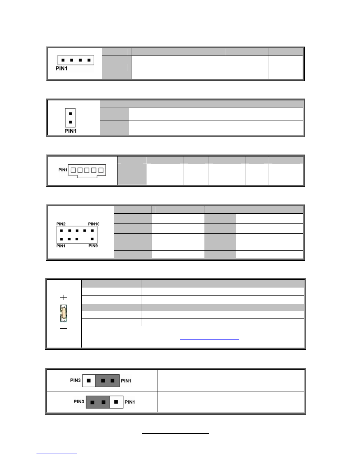
J39/J47/J48: SGPIO Header
Pin Signal Pin Signal
1 SMB SCL 2 SGPIO Data1
3 SMB SDA 4 SGPIO Data0
5 GND 6 SGPIO LOAD
7 KEY 8 SGPIO Clock
9 3.3V standby 10 BP HDD FAULT
ID_LED: ID LED
Pin Signal
+
V3AUX
-
GND
State Color Description
On Blue System identified
Off Off System not identified
NOTE: The ID LED can be activated remotely using IPMI.
Please visit the TYAN Web Site at http://www.tyan.com
to download the latest
IPMI Configuration Guide for more details.
JP7:ME update function set
Pin1-Pin2: NORMAL (Default)
Pin2-Pin3: CLOSE (ME update function)
 Loading...