

TYAN S5501 Notice

http://www.tyan.com
1
S5501
Version 1.0
Copyright
Copyright © 2009 MiTAC International Corporation. All rights reserved. TYAN® is a
registered trademark of MiTAC International Corporation.
Trademark
All registered and unregistered trademarks and company names contained in this
manual are property of their respective owners including, but not limited to the
following.
TYAN® is a trademark of MiTAC International Corporation.
Intel
®
Clarkdale, Lynnfield and combinations thereof are trademarks of Intel
Corporation.
AMI, AMI BIOS are trademarks of AMI Technologies.
Microsoft, Windows are trademarks of Microsoft Corporation.
SuSE is a trademark of Novell.
IBM, PC, AT, and PS/2 are trademarks of IBM Corporation.
Notice
Information contained in this document is furnished by MiTAC International
Corporation and has been reviewed for accuracy and reliability prior to printing.
MiTAC assumes no liability whatsoever, and disclaims any express or implied
warranty, relating to sale and/or use of TYAN products including liability or
warranties relating to fitness for a particular purpose or merchantability. MiTAC
retains the right to make changes to product descriptions and/or specifications at
any time, without notice. In no event will MiTAC be held liable for any direct or
indirect, incidental or consequential damage, loss of use, loss of data or other
malady resulting from errors or inaccuracies of information contained in this
document.

2
http://www.tyan.com
Table of Contents
Before You Begin .................................................................................................. 3
Chapter 1: Introduction .............................................................................. 5
1.1 Congratulations ............................................................................................ 5
1.2 Hardware Specifications............................................................................... 5
1.3 Software Configuration.................................................................................9
Chapter 2: Board Installation................................................................... 11
2.1 Board Image ............................................................................................... 12
2.2 Block Diagram............................................................................................ 13
2.3 Board Parts, Jumpers and Connectors....................................................... 14
2.4 Installing the Processor.............................................................................. 24
2.5 Installing the Heatsink................................................................................ 27
2.6 Finishing Installing the Heatsink................................................................ 28
2.7 Thermal Interface Material ........................................................................ 29
2.8 Tips on Installing Motherboard in Chassis.................................................30
2.9 Installing the Memory................................................................................. 32
2.10 Attaching Drive Cables............................................................................. 35
2.11 Installing Add-In Cards ............................................................................ 36
2.12 Connecting External Devices.................................................................... 37
2.13 Installing the Power Supply...................................................................... 38
2.14 Finishing up.............................................................................................. 39
Chapter 3: BIOS Setup ............................................................................. 41
3.1 BIOS Main Menu ........................................................................................ 43
3.2 Advanced Menu ..........................................................................................44
3.3 PCI PnP Menu............................................................................................ 70
3.4 Boot Menu................................................................................................... 72
3.5 Security Menu ............................................................................................. 77
3.6 Chipset Menu.............................................................................................. 78
3.7 Exit Menu.................................................................................................... 84
Chapter 4: Diagnostics............................................................................. 85
4.1
Beep Codes ................................................................................................. 85
4.2
Flash Utility................................................................................................ 85
4.3 AMIBIOS Post Code................................................................................... 86
Glossary..................................................................................................... 89
Technical Support .................................................................................... 95
3
http://www.tyan.com
Before You Begin…
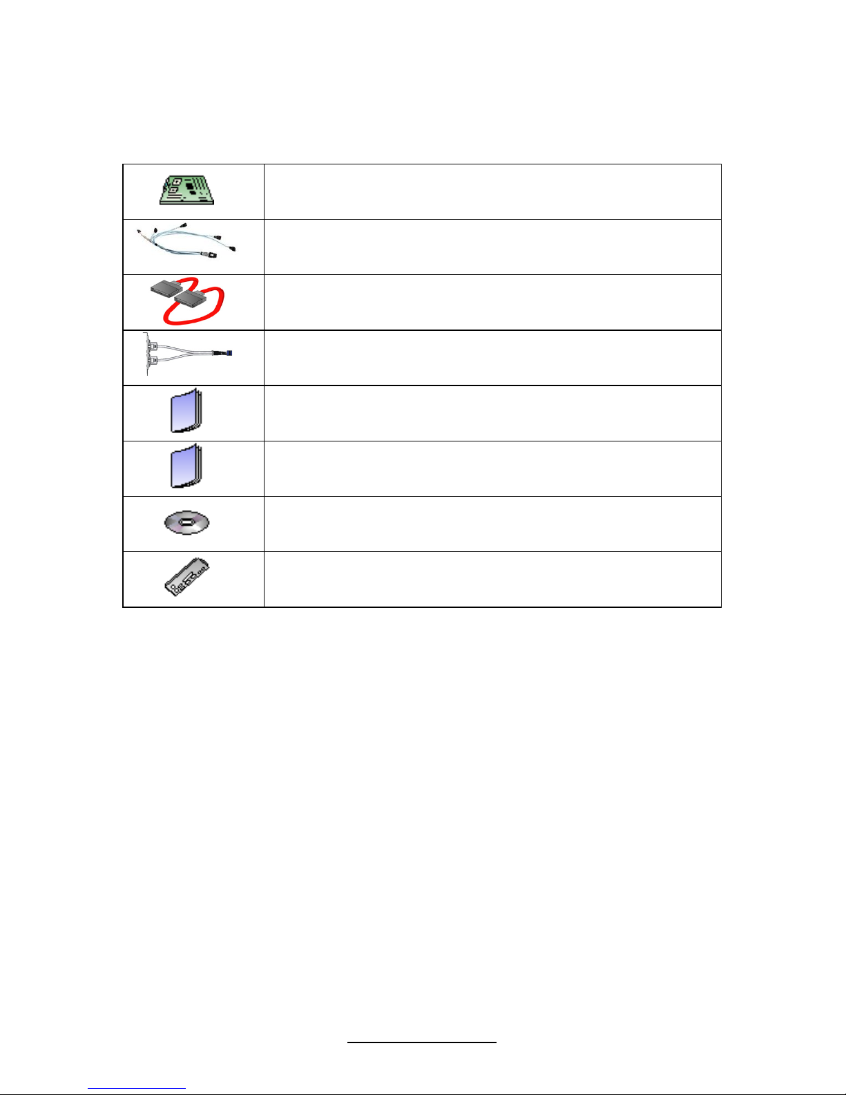
Check the box contents!
1x S5501 motherboard
2 x SAS cable
6 x Serial ATA Cable
1 x USB2.0 cable
1 x S5501 user’s manual
1 x S5501 Quick Reference guide
1 x TYAN driver CD
1 x I/O shield
If any of these items are missing, please contact your vendor/dealer for
replacement before continuing with the installation process.
NOTE: Please contact your vendor for optional cables purchase.

4
http://www.tyan.com
NOTE
5
http://www.tyan.com
Chapter 1: Introduction
1.1 Congratulations
You have purchased one of the most powerful server solutions. Based on Intel
®
Ibex Peak (PCH), ASPEED AST2050 and LSI 1068E chipsets, the S5501 is
designed to support one Clarkdale (dual core) or Lynnfield (quad core) processor
and up to 32GB RDIMM or 16GB UDIMM DDR3 registered ECC 800/1066/1333
memory, providing a rich feature set and incredible performance. Leveraging
advanced technology from Intel, the S5501 is capable of offering scalable 32 and
64-bit computing, high-bandwidth memory design, and lightning-fast PCI-E bus
implementation.
The S5501 not only empowers your company in today’s demanding IT environment
but also offers a smooth path for future application usage. All of this provides the
S5501 the power and flexibility to meet the needs of nearly any server application.
Remember to visit MiTAC’s Website at http://www.tyan.com. There you can find
information on all of MiTAC’s products with FAQs, online manuals and BIOS
upgrades.
1.2 Hardware Specifications
TYAN S5501 (S5501GM3NR)
Supported CPU
Series
Intel Xeon Processors 3400 Series
Socket Type / Q'ty LGA 1156/ (1)
Thermal Design
Power (TDP)
wattage
Max up to 95W
Processor
CPU list
Please refer to our web site for the CPU supported
list.
PCH Intel 3420
Chipset
Super I/O Winbond W83627
Supported DIMM
Qty
(6) DIMM slots
DIMM Type / Speed
DDR3 800/1066/1333* RDIMM/UDIMM / * limit 1
per channel for 1333MHz speed
Capacity Up to 32GB RDIMM/ 16GB UDIMM
Memory channel
2 Channels / Support 2 UDIMMs or 3 RDIMMs per
channel
Memory
Memory voltage 1.5V
PCI-E (2) PCI-E Gen.2 x8 slots Expansion Slots
Recommended M2091, PCI-E x16 1U riser card (left) / M2091-R,
6
http://www.tyan.com
TYAN Riser Card PCI-E x8 1U riser card (right)
Note: Only x8 signal when using M2091
Recommended
Barebone /
Chassis
1U Barebone GT20-B5501
Port Q'ty (3)
LAN
Controller Intel 82574L
Connector (6) SATA
Controller Intel 3420
Speed 3.0 Gb/s
Storage SATA
RAID RAID 0/1/10/5 (Intel Matrix RAID)
Connector type D-Sub 15-pin
Resolution 1600x1200@60Hz
Graphic
Chipset Aspeed AST2050
USB
(7) USB2.0 ports (2 at rear, 4 via cable, 1 type A
onboard)
COM (1) port (rear)
PS/2 (1) PS/2 connector
RJ-45 (2) GbE ports / (1) RJ-45 port for IPMI
Power EPS12V / SSI 24-pin + 8-pin power connectors
Front Panel (1) 2x12-pin SSI front panel header
PSMI (1) 1x5-pin header
Input /Output
SATA (6) SATA-II connectors
Chipset Winbond W83793G
Voltage
Monitors voltage for CPU, memory, chipset &
power supply
Fan Total (6) 4-pin headers
Temperature
Monitors temperature for CPU & system
environment
System
Monitoring
Others
Chassis intrusion detection / Watchdog timer
support
Onboard Chipset Onboard Aspeed AST2050
AST2050 IPMI
Feature
IPMI 2.0 compliant baseboard management
controller (BMC) / Supports storage over IP and
remote platform-flash / USB 2.0 virtual hub
Server
Management
AST2050 iKVM
Feature
24-bit high quality video compression / Dual 10/100
Mb/s MAC interfaces
Brand / ROM size AMI / 1MB
BIOS
Feature
Plug and Play (PnP) /PCI2.3 /WfM2.0 /SMBIOS2.3
/PXE boot / ACPI 2.0 power management /Power
on mode after power recovery / User-configurable
H/W monitoring / Auto-configurable of hard disk
types
Form Factor EATX
Physical
Dimension
Board Dimension 12"x13" (305x330mm)
7
http://www.tyan.com
Operating System OS supported list
Please refer to our web site for the OS supported
list.
FCC (DoC) Class A
Regulation
CE (DoC) Yes
Operating Temp. 10° C ~ 35° C (50° F~ 95° F)
Non-operating
Temp.
- 40° C ~ 70° C (-40° F ~ 158° F)
Operating
Environment
In/Non-operating
Humidity
90%, non-condensing at 35° C
RoHS RoHS 6/6 Complaint Yes
Motherboard (1) S5501 Motherboard
Manual (1) User's manual / (1) Quick Ref. Guide
Installation CD (1) TYAN installation CD
I/O Shield (1) I/O Shield
Package Contains
Cable SATA (6) SATA signal cables
Optional
accessories
Riser Card
M2091, PCI-E x16 1U riser card (left) / M2091-R,
PCI-E x8 1U riser card (right)
TYAN S5501 (S5501WGM3NR)
Supported CPU
Series
Intel Xeon Processors 3400 Series
Socket Type / Q'ty LGA 1156/ (1)
Thermal Design
Power (TDP)
wattage
Max up to 95W
Processor
CPU list
Please refer to our web site for the CPU supported
list.
PCH Intel 3420
Chipset
Super I/O Winbond W83627
Supported DIMM
Qty
(6) DIMM slots
DIMM Type / Speed
DDR3 800/1066/1333* RDIMM/UDIMM / * limit 1
per channel for 1333MHz speed
Capacity Up to 32GB RDIMM/ 16GB UDIMM
Memory channel
2 Channels / Support 2 UDIMMs or 3 RDIMMs per
channel
Memory
Memory voltage 1.5V
PCI-E (2) PCI-E Gen.2 x8 slots
Recommended
TYAN Riser Card
M2091, PCI-E x16 1U riser card (left) / M2091-R,
PCI-E x8 1U riser card (right)
Expansion Slots
Note: Only x8 signal when using M2091
Recommended
Barebone /
Chassis
1U Barebone GT20-B5501
8
http://www.tyan.com
Port Q'ty (3)
LAN
Controller Intel 82574L
Connector (2) Mini-SAS connectors (totally support 8 ports)
Controller LSI SAS1068E
Speed 3.0 Gb/s
SAS
RAID RAID 0/1/1E (LSI Integrated RAID)
Connector (6) SATA
Controller Intel 3420
Speed 3.0 Gb/s
Storage
SATA
RAID RAID 0/1/10/5 (Intel Matrix RAID)
Connector type D-Sub 15-pin
Resolution 1600x1200@60Hz
Graphic
Chipset Aspeed AST2050
USB
(7) USB2.0 ports (2 at rear, 4 via cable, 1 type A
onboard)
COM (1) port (rear)
PS/2 (1) PS/2 connector
SAS (2) Mini-SAS (4-in-1) connectors
RJ-45 (2) GbE ports / (1) RJ-45 port for IPMI
Power EPS12V / SSI 24-pin + 8-pin power connectors
Front Panel (1) 2x12-pin SSI front panel header
PSMI (1) 1x5-pin header
Input /Output
SATA (6) SATA-II connectors
Chipset Winbond W83793G
Voltage
Monitors voltage for CPU, memory, chipset &
power supply
Fan Total (6) 4-pin headers
Temperature
Monitors temperature for CPU & system
environment
System
Monitoring
Others
Chassis intrusion detection / Watchdog timer
support
Onboard Chipset Onboard Aspeed AST2050
AST2050 IPMI
Feature
IPMI 2.0 compliant baseboard management
controller (BMC) / Supports storage over IP and
remote platform-flash / USB 2.0 virtual hub
Server
Management
AST2050 iKVM
Feature
24-bit high quality video compression / Dual 10/100
Mb/s MAC interfaces
Brand / ROM size AMI / 1MB
BIOS
Feature
Plug and Play (PnP) /PCI2.3 /WfM2.0 /SMBIOS2.3
/PXE boot / ACPI 2.0 power management /Power
on mode after power recovery / User-configurable
H/W monitoring / Auto-configurable of hard disk
types
Form Factor EATX
Physical
Dimension
Board Dimension 12"x13" (305x330mm)
9
http://www.tyan.com
Operating System OS supported list
Please refer to our web site for the OS supported
list.
FCC (DoC) Class A
Regulation
CE (DoC) Yes
Operating Temp. 10° C ~ 35° C (50° F~ 95° F)
Non-operating
Temp.
- 40° C ~ 70° C (-40° F ~ 158° F)
Operating
Environment
In/Non-operating
Humidity
90%, non-condensing at 35° C
RoHS RoHS 6/6 Complaint Yes
Motherboard (1) S5501 Motherboard
Manual (1) User's manual / (1) Quick Ref. Guide
Installation CD (1) TYAN installation CD
I/O Shield (1) I/O Shield
SATA (6) SATA signal cables
Package Contains
Cable
SAS (2) SAS cables
Optional
accessories
Riser Card
M2091, PCI-E x16 1U riser card (left) / M2091-R,
PCI-E x8 1U riser card (right)
1.3 Software Configuration
Please visit the MiTAC Web Site at http://www.tyan.com to download the latest
AST2050 Software Configuration Guide.

10
http://www.tyan.com
NOTE
11
http://www.tyan.com
Chapter 2: Board Installation
You are now ready to install your motherboard. The mounting hole pattern of the
S5501 matches the EATX specification. Before continuing with installation, confirm
that your chassis supports an EATX motherboard.
How to install our products right… the first time
The first thing you should do is reading this user’s manual. It contains important
information that will make configuration and setup much easier. Here are some
precautions you should take when installing your motherboard:
(1) Ground yourself properly before removing your motherboard from the
antistatic bag. Unplug the power from your computer power supply and
then touch a safely grounded object to release static charge (i.e. power
supply case). For the safest conditions, MiTAC recommends wearing a
static safety wrist strap.
(2) Hold the motherboard by its edges and do not touch the bottom of the
board, or flex the board in any way.
(3) Avoid touching the motherboard components, IC chips, connectors,
memory modules, and leads.
(4) Place the motherboard on a grounded antistatic surface or on the antistatic
bag that the board was shipped in.
(5) Inspect the board for damage.
The following pages include details on how to install your motherboard into your
chassis, as well as installing the processor, memory, disk drives and cables.
NOTE
DO NOT APPLY POWER TO THE BOARD IF IT HAS BEEN
DAMAGED.
12
http://www.tyan.com
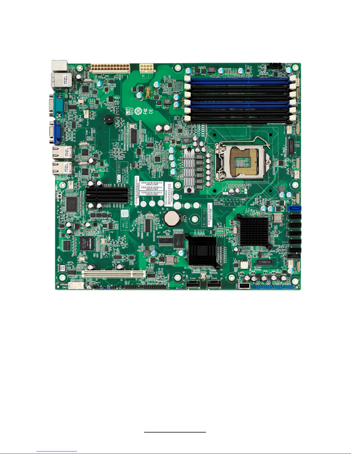
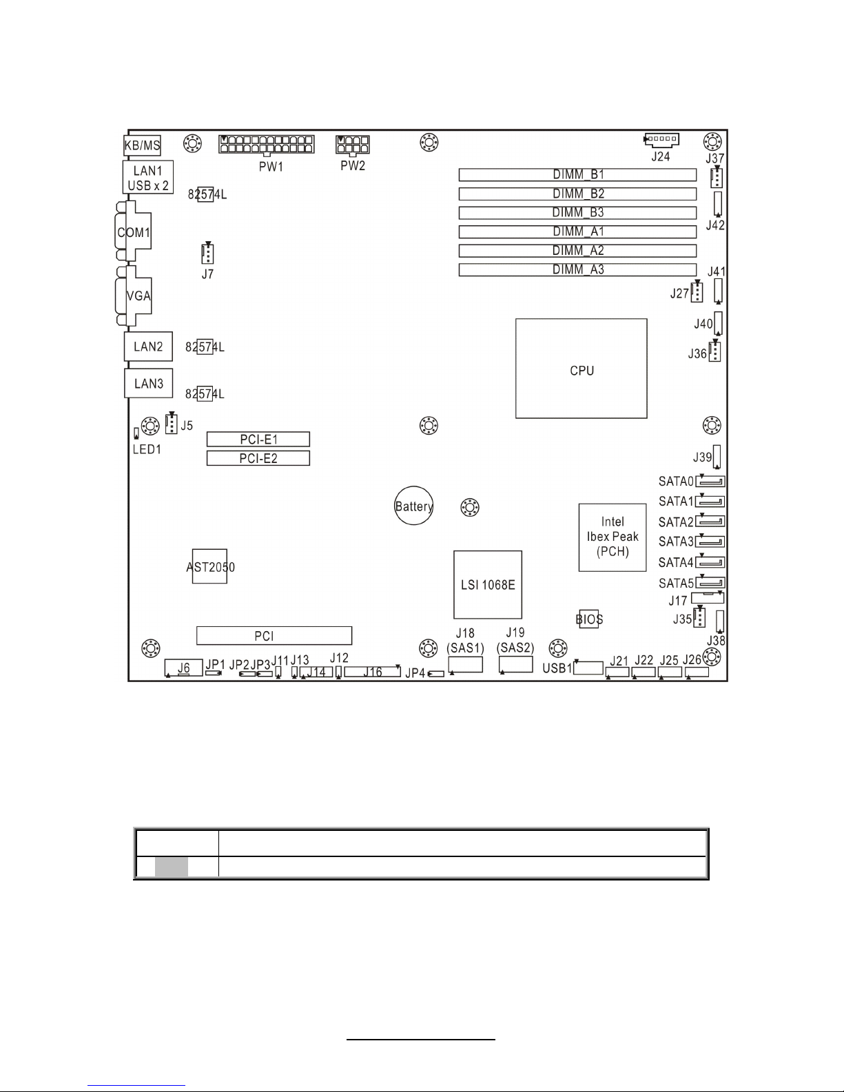
2.1 Board Image
S5501
This picture is representative of the latest board revision available at the time of
publishing. The board you receive may or may not look exactly like the above
picture.
13
http://www.tyan.com
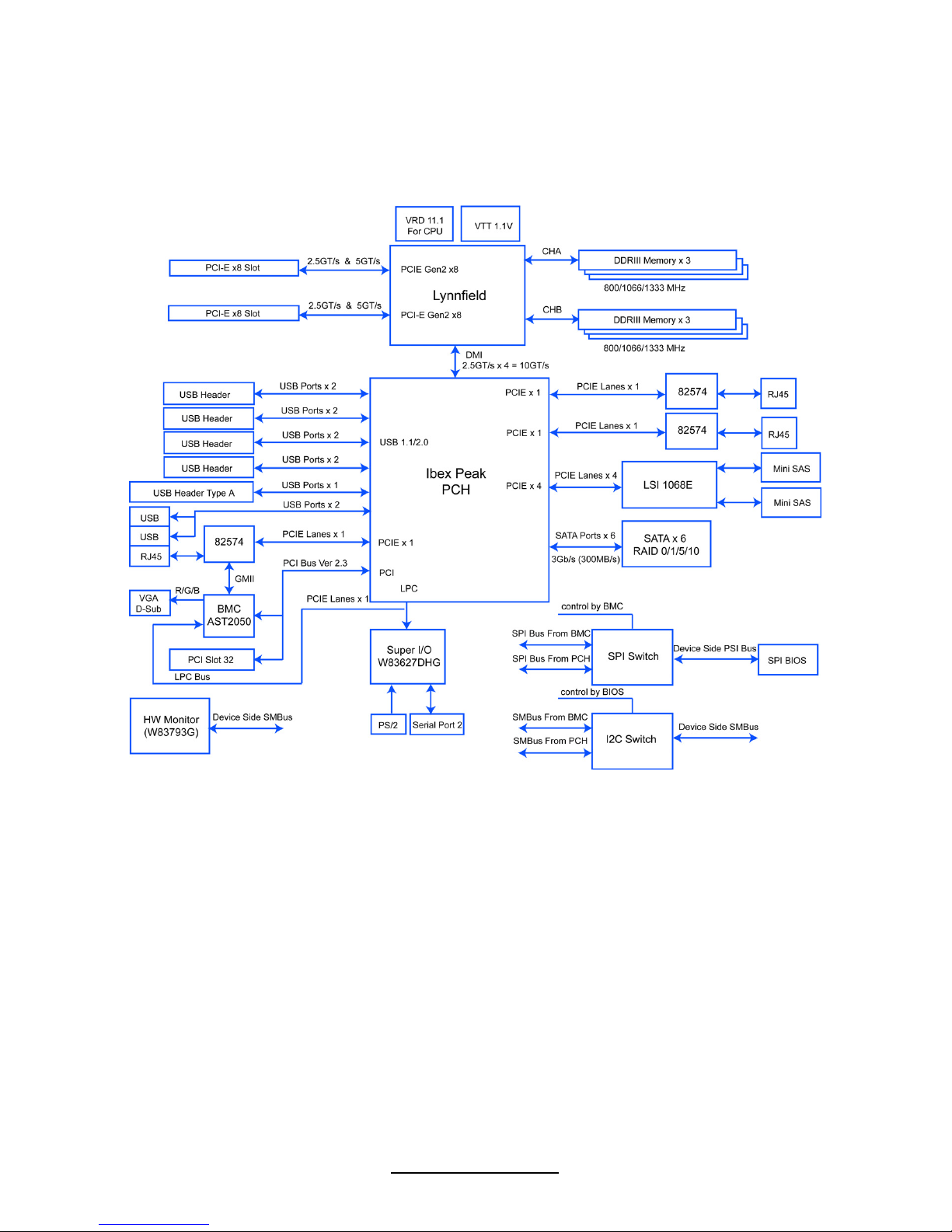
2.2 Block Diagram
S5501
14
http://www.tyan.com
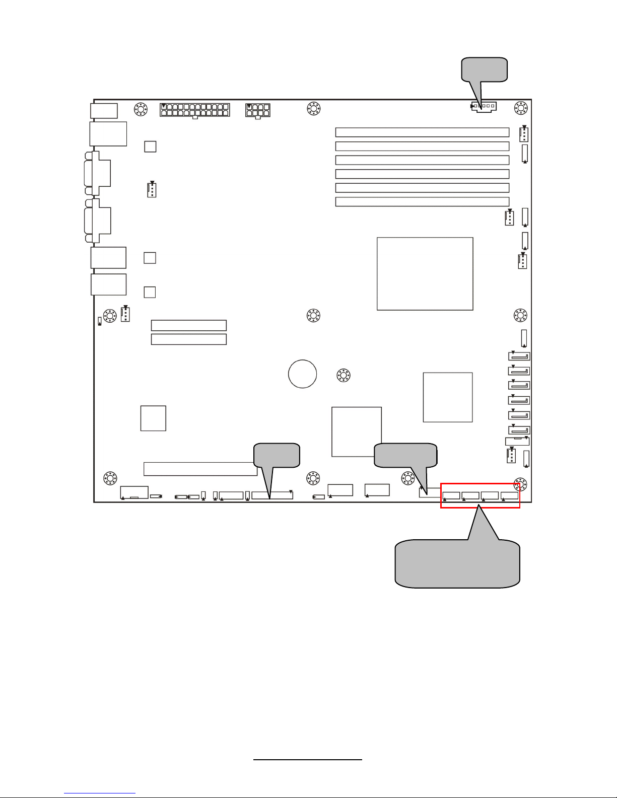
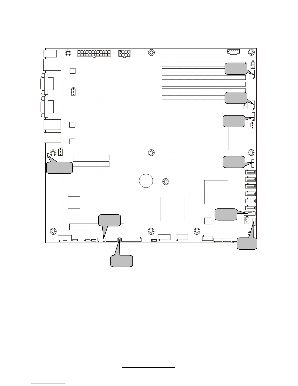
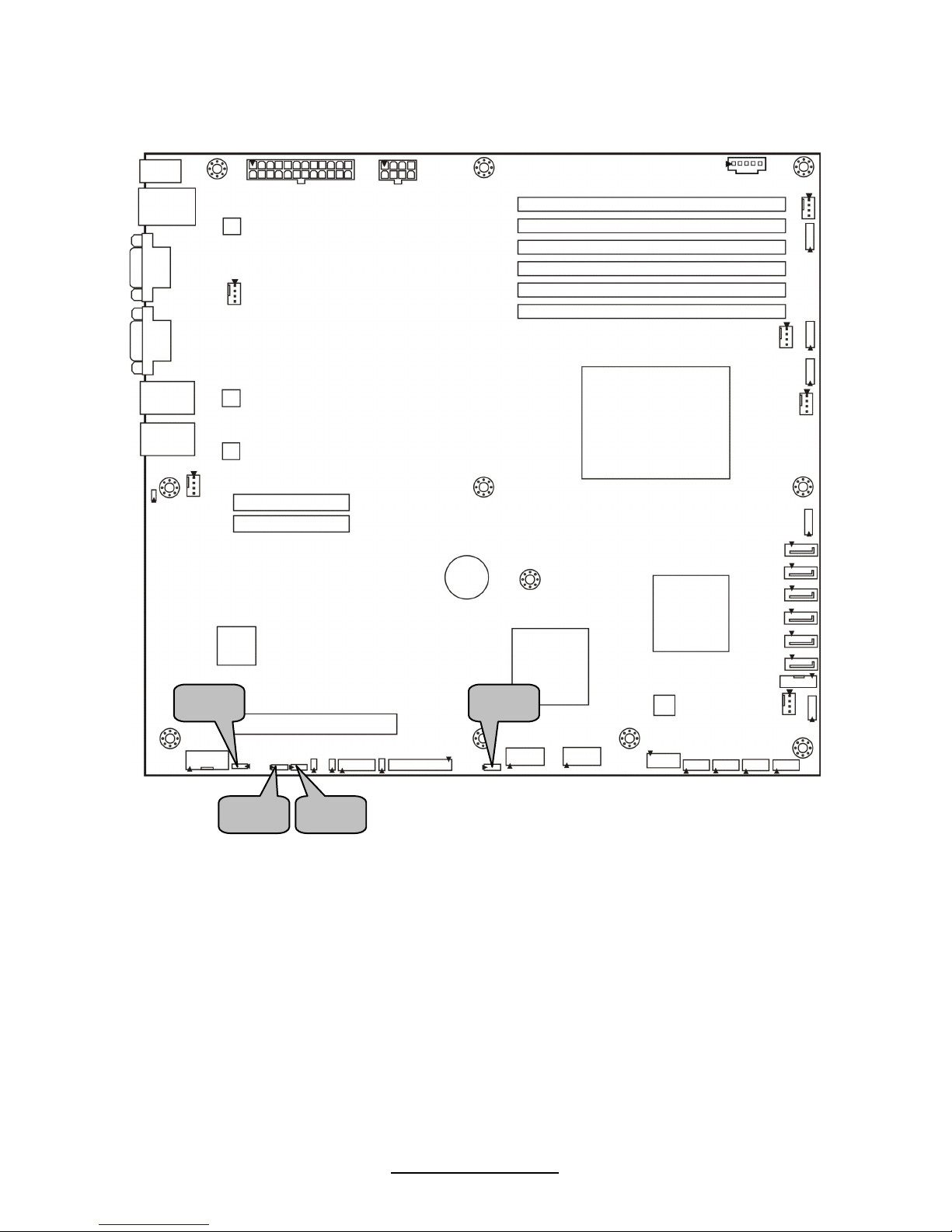
2.3 Board Parts, Jumpers and Connectors
S5501
This diagram is representative of the latest board revision available at the time of
publishing. The board you receive may not look exactly like the above diagram.
Jumper Legend
OPEN - Jumper OFF, without jumper cover
CLOSED – Jumper ON, with jumper cover

15
http://www.tyan.com
Jumper/Connector Function
J5/J7/J27/J35/J36/J37 4-pin Fan connector
J38/J39/J40/J41/J42 8-pin 4056 Fan Header
J21/J22/J25/J26 (blue) USB Front Panel Header
USB1 Type-A USB Connectors
LED1 ID LED
J6 COM2 Header
J12 LAN3 LED Header
J13 Chassis Intrusion Jumper
J14 Port80 Header
J16 Front Panel Connector
J17 ICH SGPIO Header
J24 PSMI Connector
J11 Enable/Disable BMC Jumper
JP1 Clear CMOS Jumper
JP2/JP3 COM switch Jumper
JP4 (S5501WGM3NR only) Enable/Disable SAS1068E Jumper
16
http://www.tyan.com
USB1
J24
J16
(from left to right)
J21/J22/J25/J26
17
http://www.tyan.com
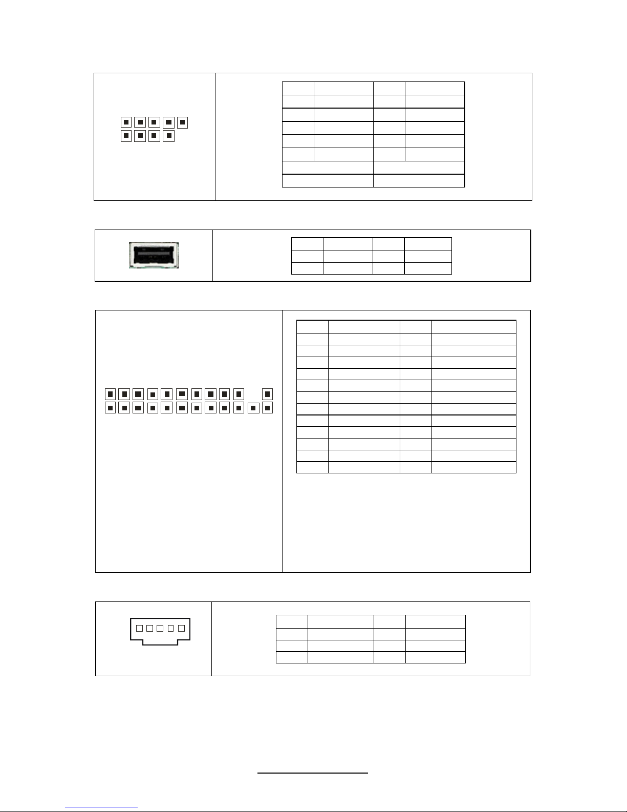
J21/J22/J35/J26: USB Front Panel Header (Blue)
10
9
2
1
Pin Signal Pin Signal
1 PWR_5V 2 PWR_5V
3 USB_N1 4 USB_N2
5 USB_P1 6 USB_P2
7 GND 8 GND
9 KEY 10 GND
USB2: J21 USB3: J22
USB4: J25 USB5: J26
USB1: Type-A USB Connector
Pin Signal Pin Signal
1 +5v 2 USB D3 USB D+ 4 GND
J16: Standard Front Panel Connector
2
4
2
3
2
1
Use this header to connect some control
or signal wires from motherboard to
chassis, such as HDD LED, power LED,
and ID LED.
Pin Signal Pin Signal
1 Power LED+ 2 5V_AUX
3 KEY 4 ID LED+
5 Power LED- 6 ID LED7 HDLED+ 8 Fault_LED19 HDLED- 10 Fault_LED211 Power SW# 12 LAN1 ACTLED+
13 GND1 14 LAN1 ACTLED15 Reset SW# 16 SMBUS SDA
17 GND2 18 SMBUS SCL
19 ID SW 20 INTRD#
21 Temp Sensor 22 LAN2 ACTLED+
23 NMI_SW# 24 LAN2 ACTLED-
J24 (PSMI): PSMI Connector
1
Pin Signal Pin Signal
1 SMB_CLK 2 SMB_DAT
3 SMBALERT 4 GND
5 V3P3
18
http://www.tyan.com
J40
J39
J38
J41
J42
J13
LED1
J17
J12
19
http://www.tyan.com
J12: LAN3 LED Header
1
Pin Signal
1 LAN3 LED+
2 LAN3 LED-
J13: Chassis Intrusion Header
1
Pin Signal Pin Signal
1 INTRUDER# 2 GND
J17: PCH SGPIO Header
1
092
1
Pin Signal Pin Signal
1 SMBCLK 2 SDATAOUT0
3 SMBDAT 4 SDATAOUT1
5 GND 6 SLOAD
7 KEY 8 SCLOCK
9 NC 10 HD_ERR_LED
J38/J39/J40/J41/J42: 8-pin 4056 Fan Header
1
8
Use this header to connect the cooling fan to
your motherboard to keep the system at
optimum performance levels.
Pin Signal Pin Signal
1 PWM1 2 +12V
3 TACH1 4 GND
5 GND 6 TACH2
7 +12V 8 PWM2
LED1: ID LED
+
_
Pin Signal
+ P3V3_AUX
- ID_SW_L
State Color Description
On Blue System identified
Off Off System not identified
NOTE: IPMI can activate ID LED from remote site.
Please visit the MiTAC Web Site at http://www.tyan.com
to download
the latest AST2050 or Server Engines Pilot2 Software Configuration
Guide for IPMI settings.
20
http://www.tyan.com
J37
J36
J27
J7
J35
SATA0
SATA1
SATA2
SATA3
SATA4
SATA5
J5
J6
J14
J11
21
http://www.tyan.com
J5/J7/J27/J35/J36/J37: 4-pin Fan Header
Use these headers to connect the cooling fans to the
motherboard to keep the system stable and reliable.
Pin Signal Pin Signal
1 GND 2 +12V
3 Tachometer 4 Fan PWR (speed Control)
J14: Port 80 Connector
1
2
1
3
1
4
Pin Signal Pin Signal
1 SMBUS_3V3_CLK 2 P3V3
3 SMBUS_3V3_DATA 4 FRAME
5 CLK-33M_P80 6 GND
7 GND 8 LAD3
9 PLTRST 10 LAD2
11 NC 12 LAD1
13 NC 14 LAD0
J6 (COM2): COM2 Header
1
2
10
9
Pin Signal Pin Signal
1 DCD 2 DSR
3 RXD 4 RTS
5 TXD 6 CTS
7 DTR 8 RI
9 GND 10 KEY
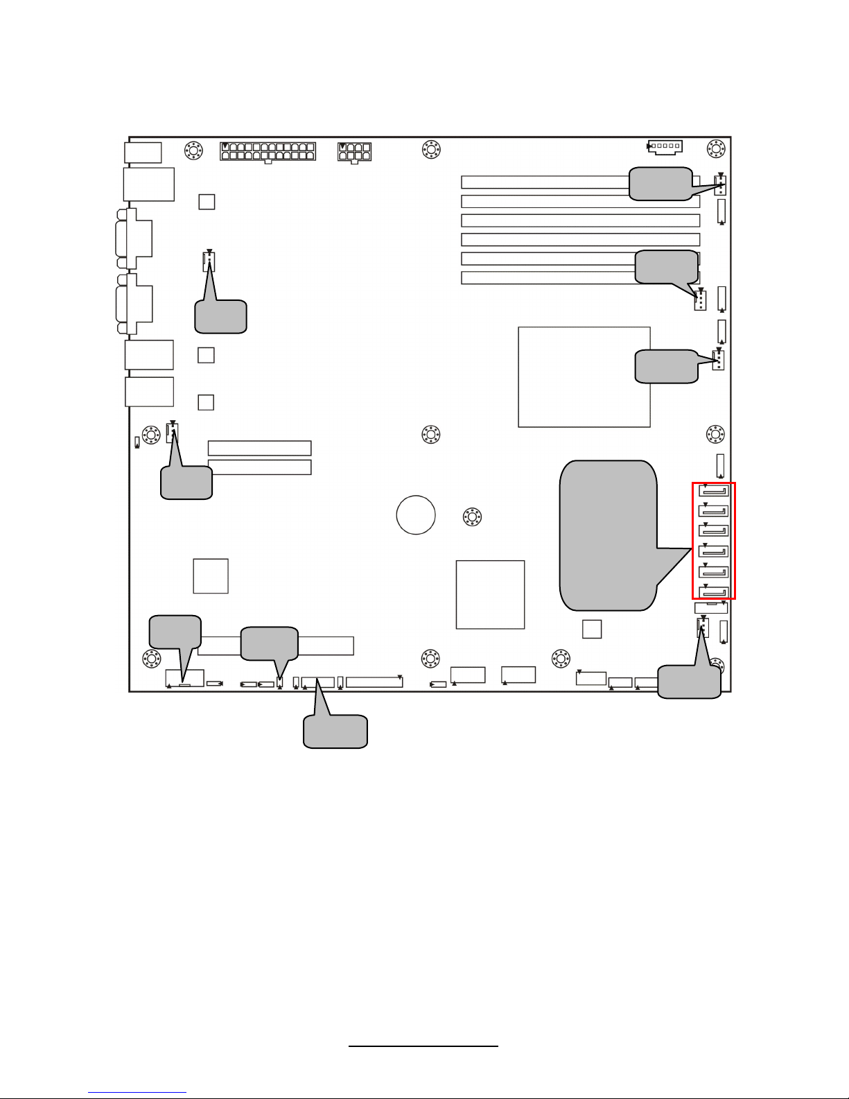
SATA0/1/2/3/4/5: SATA RAID Connector
7
1
Connects to the Serial ATA ready drives via the Serial ATA
cable.
Pin 1 Pin 2 Pin 3 Pin 4 Pin 5 Pin 6 Pin 7
GND TXP TXN GND RXN RXP GND
J11: Enable/Disable BMC Jumper
1
Pin 1-2 Open: Enable (Default)
1
Pin 1-2 Closed: Disable
22
http://www.tyan.com
JP2
JP4
JP3
JP1

23
http://www.tyan.com
JP1 (CCMOS): Clear CMOS Jumper
1
3
Normal
(Default)
3
1
Clear
Use this jumper when you forgot your system/setup
password or need to clear system BIOS setting.
How to clear the CMOS data
- Power off system and disconnect power
supply from AC source
- Use jumper cap to close Pin_2 and 3 for
several seconds to Clear CMOS
- Replace jumper cap to close Pin_1 and 2
Reconnect power supply to AC source
Power on system
JP2/JP3: COM Switch Jumper
3
1
Pin 1-2 closed: COM2 (Default)
1
3
Pin 2-3 closed: BMC UART2 to COM2
JP4: Enable/Disable SAS 1068E Jumper (S5501WGM3NR only)
3
1
Pin 1-2 closed: Enable (Default)
1
3
Pin 2-3 closed: Disable
24
http://www.tyan.com
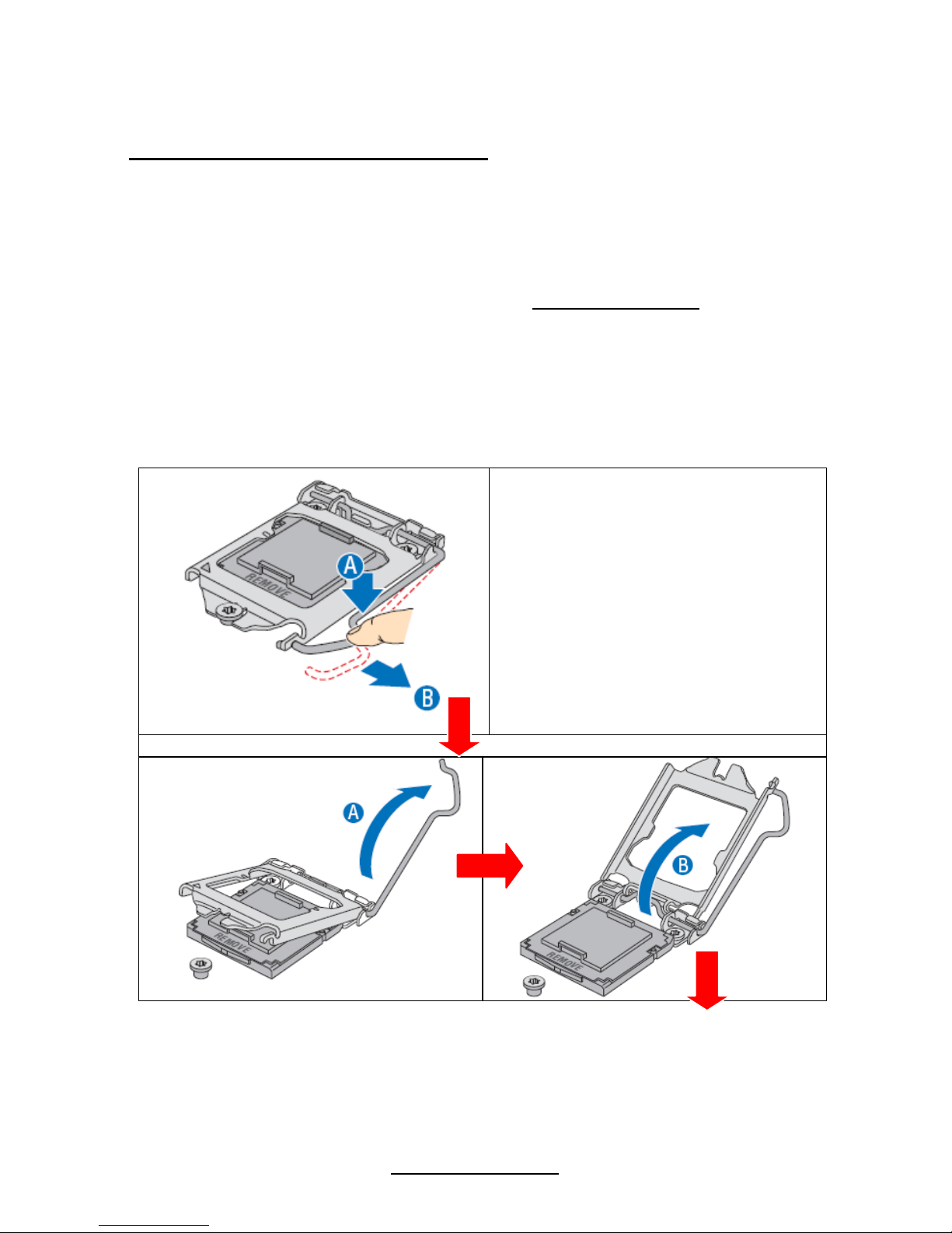
2.4 Installing the Processor
Processor Installation (LGA1156 Socket)
The processor should be installed carefully. Make sure you are wearing an antistatic
strap and handle the processor as little as possible. If your mainboard has dual
CPU sockets, please note that both processors of the same type and frequency
are required for optimal system performance.
The S5501 supported Intel
®
processors are listed in section 1.2 Hardware
Specifications on page 5. Check our website at http://www.tyan.com
for the latest
processor support.
MiTAC is not liable for damage as a result of operating an unsupported
configuration.
The diagram is provided as a visual guide to help you to install the socket processor
and may not be an exact representation of the processor you have.
Step1:
Locate the processor socket
and open the socket lever
Step 2: Open the load plate
25
http://www.tyan.com
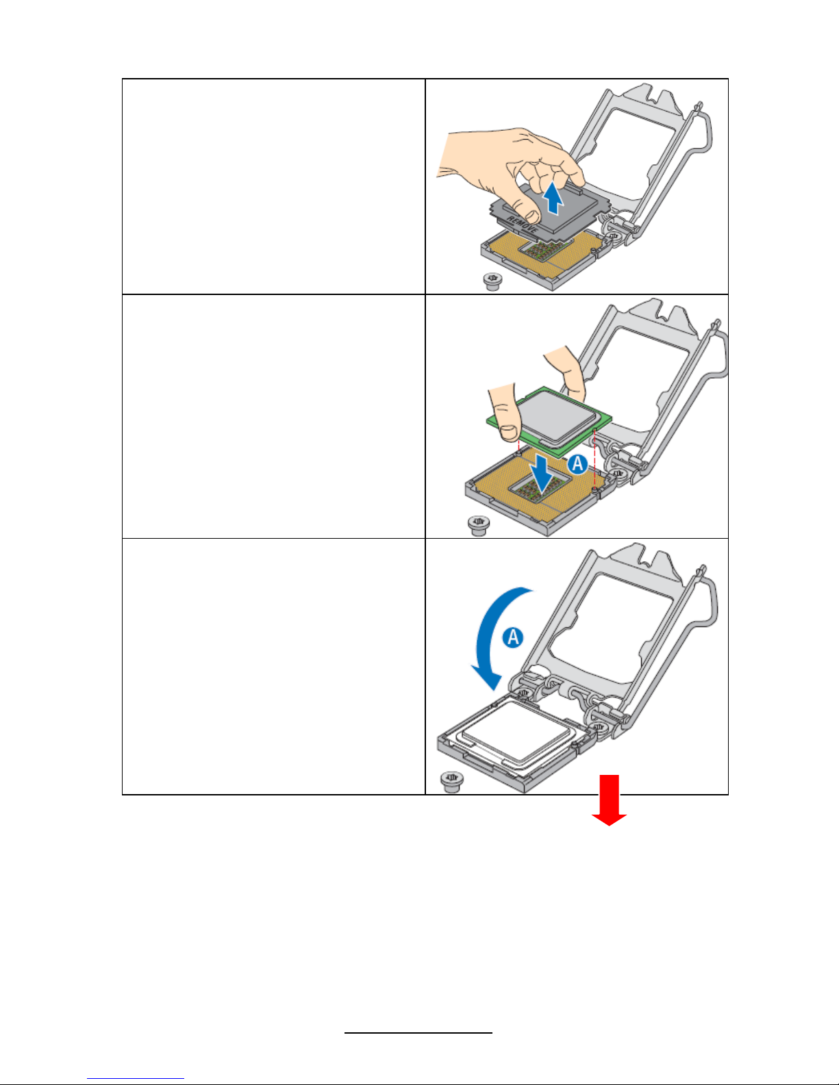
Step3: Remove the socket protective
cover
Step4: Align the processor cutouts to
match the two socket pins, and insert
the processor into the socket
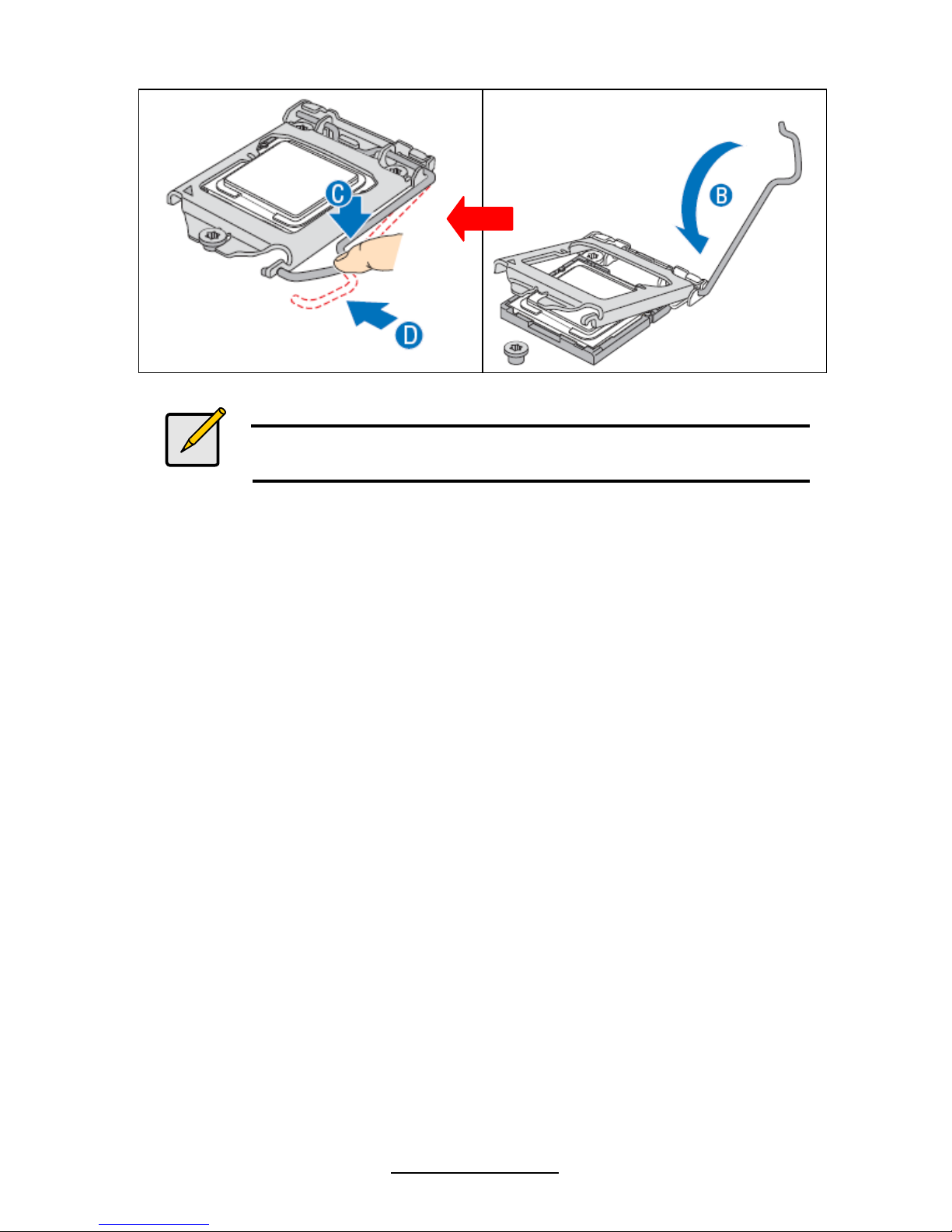
Step5: Close the load plate (see letter
“A”), close the socket lever, and
ensure the load plate tab engages
under the socket lever when fully
closed (see letter “B” and “C”).
26
http://www.tyan.com
Notes
Make sure the alignment triangle mark and the alignment triangle
cutout align correctly.
27
http://www.tyan.com
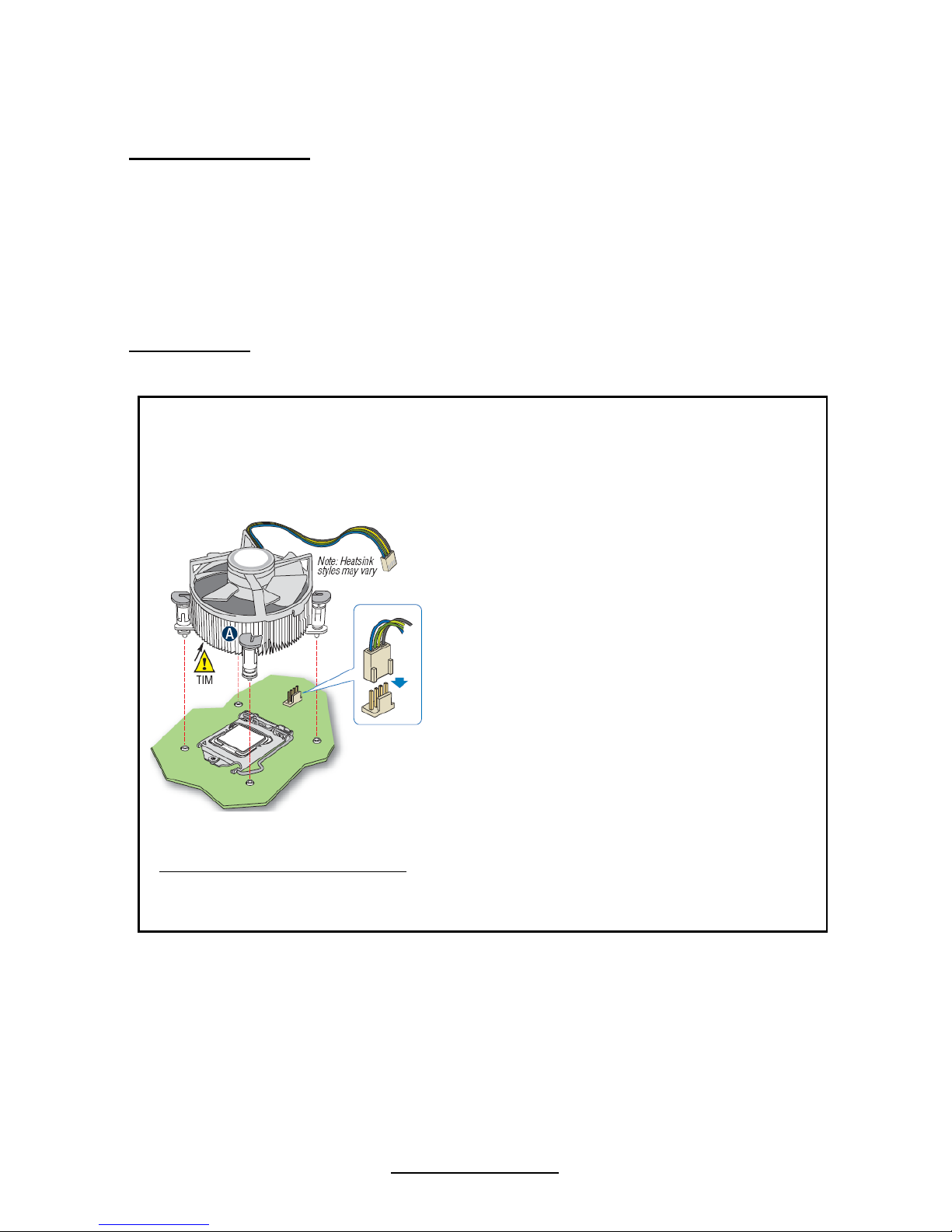
2.5 Installing the Heatsink
Heatsink Installation
After installing the processor, you should proceed to install the heat sink. The CPU
heat sink will ensure that the processor do not overheat and continue to operate at
maximum performance for as long as you own them. The overheated processor is
dangerous to the motherboard.
For the safest method of installation and information on choosing the appropriate
heat sink, using heat sinks validated by Intel
®
. Please refer to Intel’ ®s website at
www.Intel.com
.
The following diagram illustrates how to install heat sink onto the CPU of S5501.
1. If a protective film covers the thermal interface
material (TIM) on the underside of the heatsink,
remove the protective film.
2. Align heatsink fins to the front and back of the
chassis for correct airflow. Airflow goes from frontto-back of chassis.
3. Each heatsink has four captive fasteners and
should be tightened as shown
4. Using a #2 Phillips* screwdriver, finger-tighten
each fastener diagonally, according to the whitecircled numbers.
5. Securely re-tighten each fastener again in the
same order as performed in Step 4.
6. Attach fan power cable to server board as
shown.
7. Reinstall and reconnect any parts you removed
or disconnected to reach the processor sockets.
2U Reference Heatsink Assembly 8. Replace the server's cover and reconnect the
AC power cord. Refer to the documentation that
came with your server chassis for instructions on
installing the server's cover.
28
http://www.tyan.com
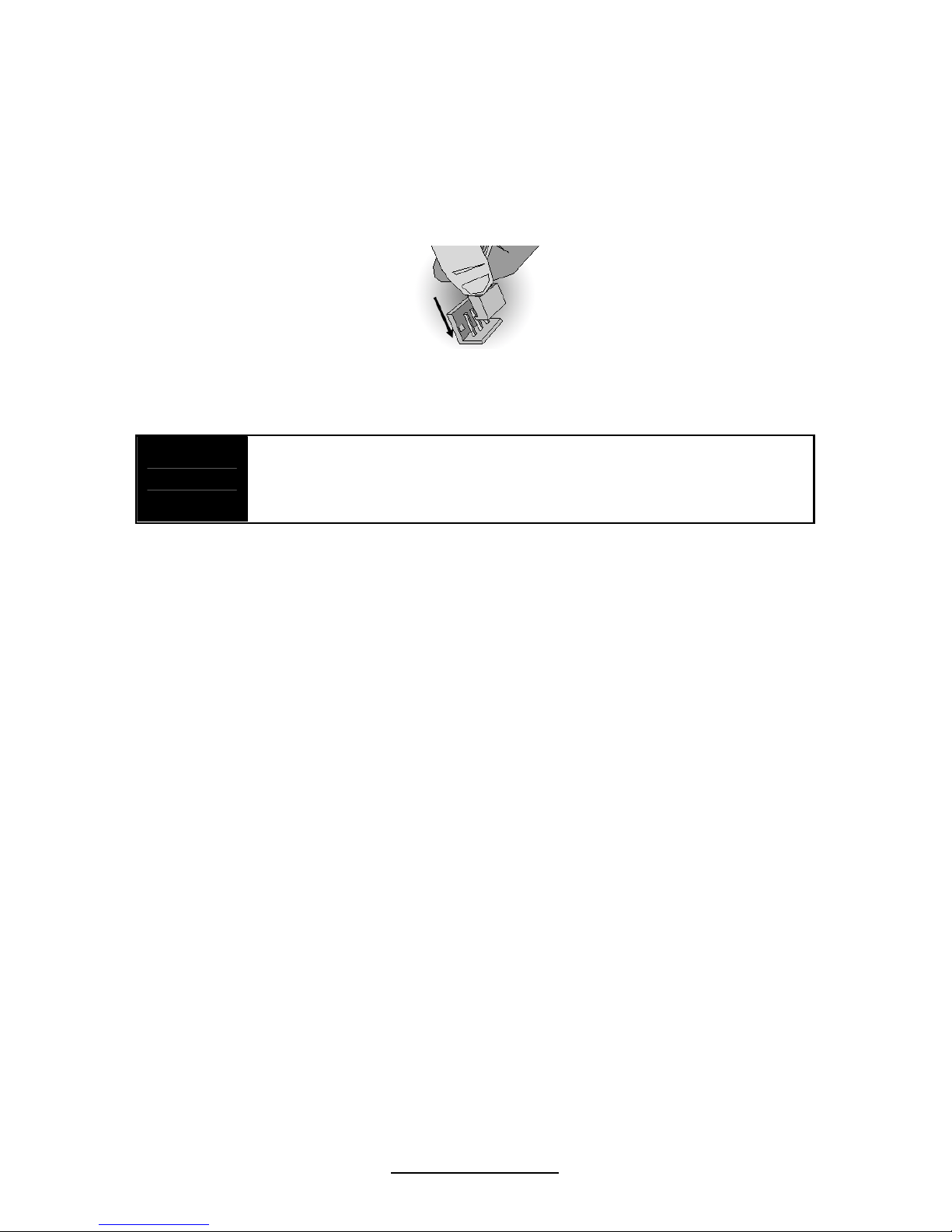
2.6 Finishing Installing the Heatsink
After you have finished installing the heat sink onto the processor and socket,
attach the end wire of the fan (which should already be attached to the heat sink) to
the motherboard. The following diagram illustrates how to connect fans onto the
motherboard.
Once you have finished installing all the fans you can connect your drives (hard
drives, CD-ROM drives, etc.) to your motherboard.
NOTE
Adequate system airflow is required to ensure SAS controller
and attached drives work properly. It is the responsibility of the
system builder to ensure adequate system airflow by choosing
the correct chassis and system components.
29
http://www.tyan.com
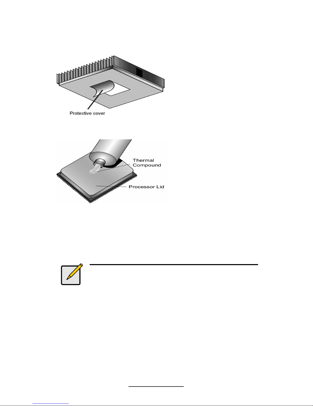
2.7 Thermal Interface Material
There are two types of
thermal interface materials
designed for use with the
processors.
The most common material
comes as a small pad
attached to the heatsink at
the time of purchase. There
should be a protective cover
over the material. Take care
not to touch this material.
Simply remove the protective
cover and place the heatsink
on the processor.
The second type of interface
material is usually packaged
separately. It is commonly
referred to as ‘thermal
compound’. Simply apply a
thin layer on to the CPU lid
(applying too much will
actually reduce the cooling).
Note:
Always check with the manufacturer of the heatsink &
processor to ensure the Thermal Interface material is
compatible with the processor & meets the
manufacturer’s warranty requirements.
 Loading...