

TYAN TIGER I7322DP, Tiger i7322DP S5353, S5353 User Manual

http://www.tyan.com
1
Tiger i7322DP
///
S5353
Version 1.0
Copyright
Copyright © TYAN Computer Corporation, 2005. All rights reserved. No part of
this manual may be reproduced or translated without prior written consent from
TYAN Computer Corp.
Trademark
All registered and unregistered trademarks and company names contained in
this manual are property of their respective owners including, but not limited to
the following.
TYAN, Taro and Tiger i7322DP are trademarks of TYAN Computer Corporation.
AMD, Opteron, and combinations thereof are trademarks of AMD Corporation.
Nvidia and nForce are trademarks of Nvidia Corporation
Microsoft, Windows are trademarks of Microsoft Corporation.
SuSE,is a trademark of SuSE AG.
Linux is a trademark of Linus Torvalds
IBM, PC, AT, and PS/2 are trademarks of IBM Corporation.
Winbond is a trademark of Winbond Electronics Corporation.
Notice
Information contained in this document is furnished by TYAN Computer
Corporation and has been reviewed for accuracy and reliability prior to printing.
TYAN assumes no liability whatsoever, and disclaims any express or implied
warranty, relating to sale and/or use of TYAN products including liability or
warranties relating to fitness for a particular purpose or merchantability. TYAN
retains the right to make changes to product descriptions and/or specifications
at any time, without notice. In no event will TYAN be held liable for any direct or
indirect, incidental or consequential damage, loss of use, loss of data or other
malady resulting from errors or inaccuracies of information contained in this
document.

http://www.tyan.com
2
Table of Contents
Chapter 1: Introduction
1.1 Congratulations Page 5
1.2 Hardware Specifications Page 5
Chapter 2: Board Installation
2.1 Board Image Page 8
2.2 Block Diagram Page 9
2.3 Board Parts, Jumpers and Connectors Page 10
2.4 Mounting the Motherboard Page 22
2.5 Installing the Memory Page 23
2.6 Installing the Processor and Cooling Fan Page 25
2.7 Attaching Drive Cables Page 27
2.8 Installing Add-In Cards Page 29
2.9 Installing Optional SO-DIMM Modules Page 32
2.10 Connecting External Devices Page 33
2.14 Installing the Power Supply Page 34
2.15 Finishing Up Page 35
Chapter 3: BIOS
3.1 About the BIOS` Page 37
3.2 Main BIOS Setup Page 39
3.3 Main Page 40
3.4 Advanced Page 46
3.5 Security Page 58
3.6 Power Page 59
3.7 Boot Page 60
3.8 Exit Page 61
Chapter 4: SATA/RAID Setup
4.1 BIOS Configuration Page 63
4.2 Installing Serial ATA (SATA) hard disks Page 63
4.3 Adaptec RAID Configuration Utility Page 64
4.4 Manage Array Page 64
4.5 Create Array Page 66
4.6 Add/Delete Hotspare Page 68
4.7 Initialize Drives Page 68
4.8 Disk Utilities Page 70
Chapter 5: Diagnostics
5.1 Beep Codes Page 73
5.2 Flash Utility Page 73
5.3 BIOS Post Code Page 74
Appendix I: SMDC Information
Page 79
Appendix II: How to Make a Driver Diskette
Page 81
Glossary
Page 83
Technical Support
Page 89

http://www.tyan.com
3
Check the box contents!
The retail motherboard package should contain the following:
1 x Tiger i7322DP S5353 motherboard
1 x 34-Pin floppy drive cable
2 x Ultra-DMA-133/100/66/33 IDE cable
1 x Tiger i7322DP S5353 User’s Manual
1 x Tiger i7322DP S5353 Quick Reference Guide
1 x TYAN driver CD
1 x I/O shield
1 x Cable set (9 pin serial and 24 pin parallel)
2 x CEK Spring
1 x Serial ATA power cable
2 x Serial ATA cable
1 x USB2.0 cable
If any of these items are missing, please contact your vendor/dealer for
replacement before continuing with the installation process.

http://www.tyan.com
4
NOTE

http://www.tyan.com
5
Chapter 1: Introduction
1.1 - Congratulations
Congratulations on your purchase of the powerful Dual Intel processor solution,
the Tiger i7322DP S5353. Based on Intel E7320 chipset, the S5353 offers
exceptional performance. Compatible with EPS12V power supplies, the ATX
form factor S5353 features an onboard XGI XG20 16MB PCI VGA, two Gigabit
Ethernet ports, one 10/100 Ethernet port and SATA/RAID, which provides a
versatile solution for your server needs.
Remember to visit TYAN’s Website at http://www.tyan.com. There you can find
information on all of TYAN’s products with FAQ’s, online manuals and BIOS
upgrades.
1.2 - Hardware Specifications
Processors
• Two mPGA604 sockets
• Supports up to two 64-bit Intel®
Xeon processors (including dual-core
processors) with 800MHz FSB
Expansion Slots
• One PCI-X 1.0 64-bit/66MHz slot
• One 32-bit/33MHz PCI 2.3 slot
• One TYAN TARO SO-DIMM socket
• One x4 PCIe connector
Chipset
• Intel Lindenhurst-VS (E7320) MCH
• Intel Hance Rapids (6300ESB)
South Bridge
• SMSC DME1737 LPC I/O chip
System Management
• SMSC DME1737 and EMC6D102 (or
ADM1027) w/ hardware monitoring
• Two 3+1-pin CPU Fan headers w/
tachometer input and programmable
temperature-sensing fan speed
control
Integrated LAN Controllers
• One 10/100 LAN controller
―One Intel i82551QM LAN
controller
―Operating at 32bit/33MHz
interface
• Two GbE LAN controllers
―One Broadcom BCM5721 PCI-
Express GbE LAN controller
―One Broadcom BCM5705(W)
PCI GbE LAN controller
• Pin Headers for front panel LAN
LED
Optional Modules
•M3291, IPMI 2.0 Remote System
Management Daughter Card
-Renesas H8S2167 BMC controller
-BT, KCS, Logging support
-IPMI-over-LAN
-Remote power on/off and reset
•M7901/M7902, single/dual-channel
Ultra 320 SCSI controller TARO
card
-Adaptec AIC-7901/7902 controller
-Adaptec Host RAID 0, 1, 10

http://www.tyan.com
6
• Seven 3-pin system Fan headers, 5
w/ tachometer input and
programmable temperature-sensing
fan speed control
• Temperature and voltage monitoring
• Chassis intrusion header
• IPMB connector for optional Tyan
M3291 SMDC card
• Watchdog timer
Integrated PCI Graphics
• XGI XG20 graphics controller
• 16MB DDR frame buffer of video
memory
Memory
• Dual memory channels, 6 x DIMM
sockets
• Supports up to six DDR2-400 DIMMs
• Registered ECC memory supported
Integrated PCI IDE (6300ESB)
• Dual channel master mode support
four IDE devices
• Support for ATA-100/66/33 IDE
drives and ATAPI compliant devices
Integrated Serial ATA (6300ESB)
• Two serial ATA host controllers
embedded
• Supports two serial ports running at
1.5Gb/s
• RAID 0 or 1 supported (Windows 32-
bit Only)
• SATA activity LED connector
Back Panel I/O Ports
• Stacked PS/2 mouse & keyboard
ports
• Stacked two USB2.0 and one RJ45
10/100 ports with activity LED
• One 15-pin VGA port
• One 9-pin COM port
• Two RJ45 10/100/1000 Base-T port w/
activity LED
•M9000 SAS/SATA II TARO card
-Adaptec AIC-9405/9410 SAS
controller
-Supports up to 4-port (M9000-5)
and 8-port (M9000-10) SAS &
SATA running at 3.0Gb/s
-Adaptec HostRAID 0, 1 & 10
Integrated I/O Interfaces
• One floppy connector
• Two USB 2.0 ports (via cable)
• One COM2 port (via cable)
• One LPT port (via cable)
• TYAN 2 x 9 pin header
• 2 x 25 connector for optional IPMI
SMDC card
BIOS
• Phoenix BIOS 8Mbit Flash
• Supports APM 1.2 & ACPI 1.0
• PnP, DMI2.0, WfM2.0 power
Management
Form Factor
• SSI CEB footprint
• 10.2" x 12.0” (259mm x 305mm)
Power
• On board dual 4-phase VRM
• EPS 12V (24-pin + 8-pin) power
connectors
Regulatory
• FCC Class B (Declaration of
Conformity)
• CE (Declaration of Conformity)
• BSMI

http://www.tyan.com
7
Chapter 2: Board Installation
Precautions: The Tiger i7322DP supports SSI, EPS12V type power supplies
(24pin + 8pin) and will not operate with any other types. For proper power
supply installation procedures see page 37.
DO NOT USE ATX 2.x or ATXGES power supplies as they will damage the
board and void your warranty.
How to install our products right… the first time
The first thing you should do is reading this user’s manual. It contains important
information that will make configuration and setup much easier. Here are some
precautions you should take when installing your motherboard:
(1) Ground yourself properly before removing your motherboard from the
antistatic bag. Unplug the power from your computer power supply and
then touch a safely grounded object to release static charge (i.e. power
supply case). For the safest conditions, TYAN recommends wearing a
static safety wrist strap.
(2) Hold the motherboard by its edges and do not touch the bottom of the
board, or flex the board in any way.
(3) Avoid touching the motherboard components, IC chips, connectors,
memory modules, and leads.
(4) Place the motherboard on a grounded antistatic surface or on the
antistatic bag that the board was shipped in.
(5) Inspect the board for damage.
The following pages include details on how to install your motherboard into your
chassis, as well as installing the processor, memory, disk drives and cables.
NOTE
DO NOT APPLY POWER TO THE BOARD IF IT HAS BEEN
DAMAGED.
http://www.tyan.com
8
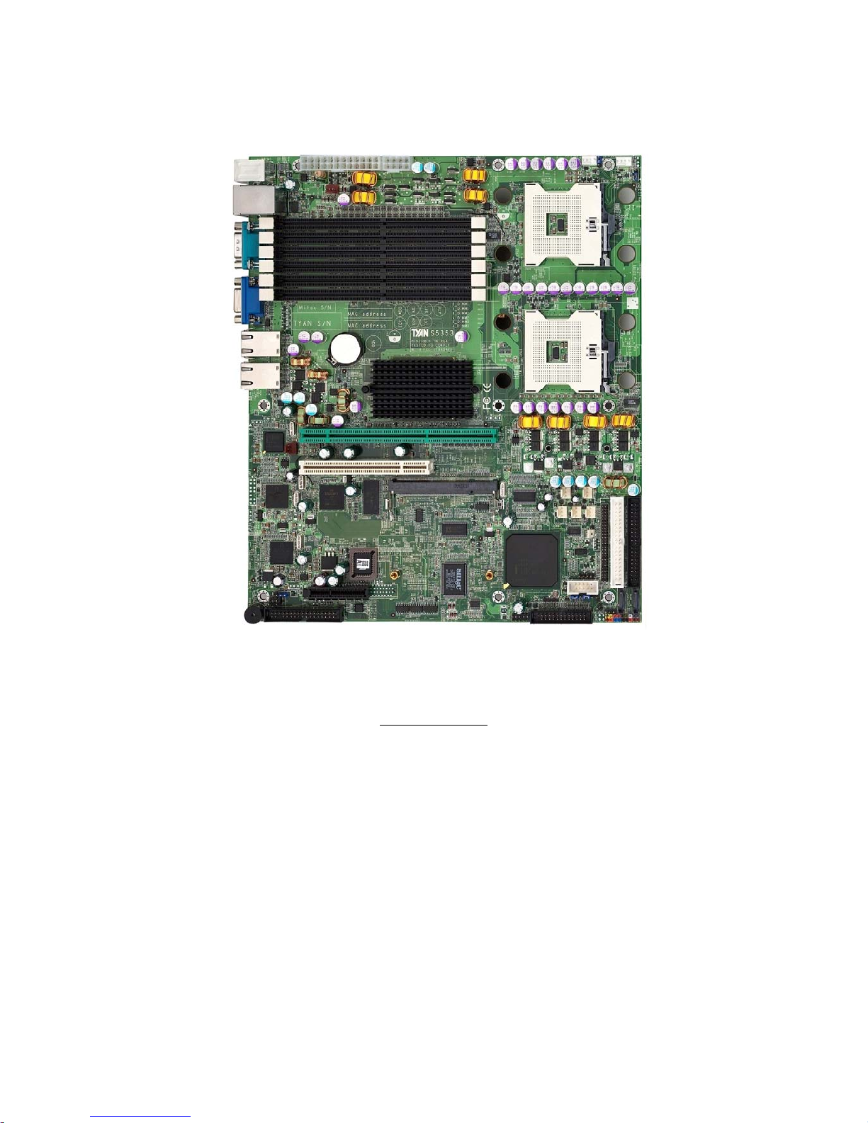
2.1- Board Image
This picture is representative of the latest board revision available at
the time of publishing. The board you receive may or may not look
exactly like the above picture.
The following page includes details on the vital components of this
motherboard.
http://www.tyan.com
9
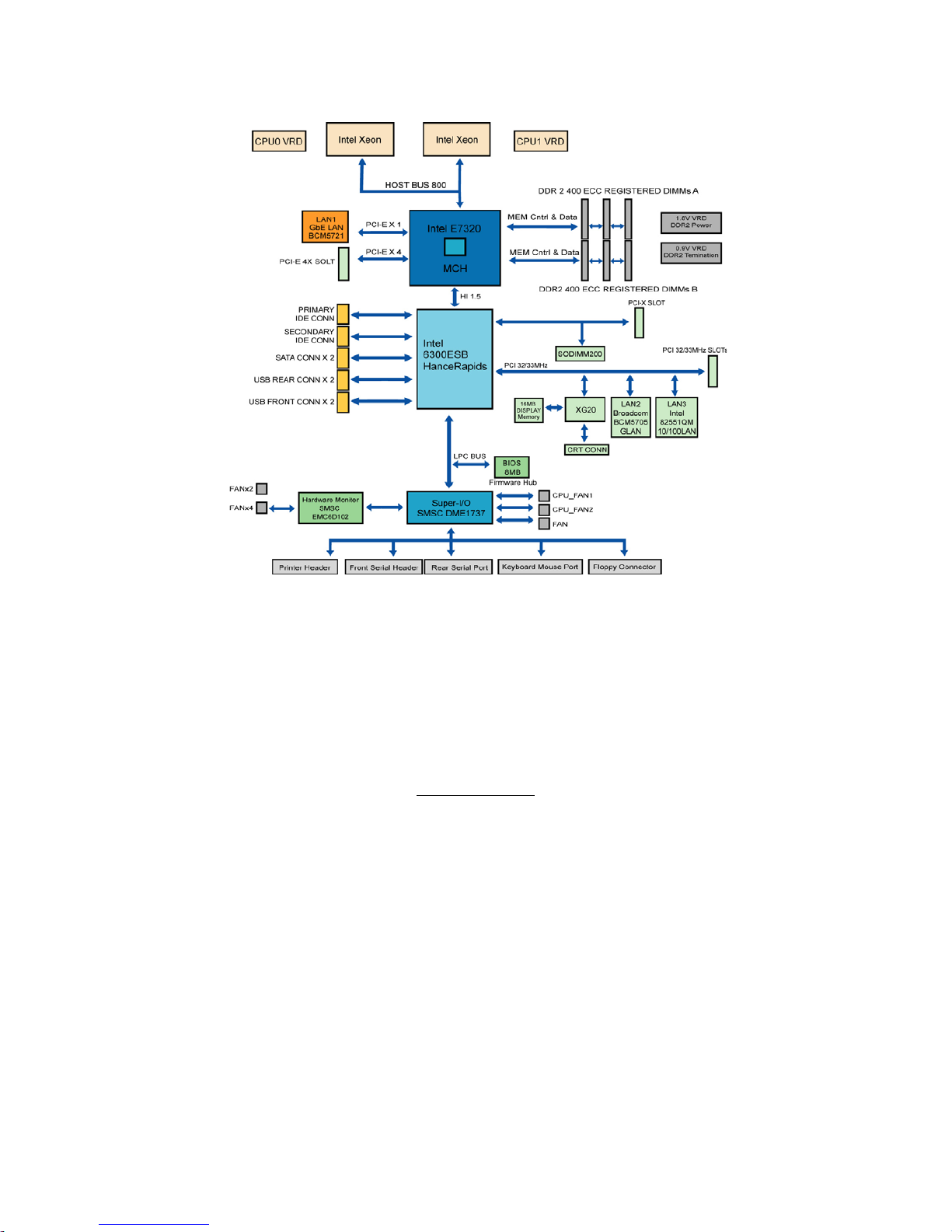
2.2 - Block Diagram
Tiger i7322DP (S5353) Block Diagram
http://www.tyan.com
10
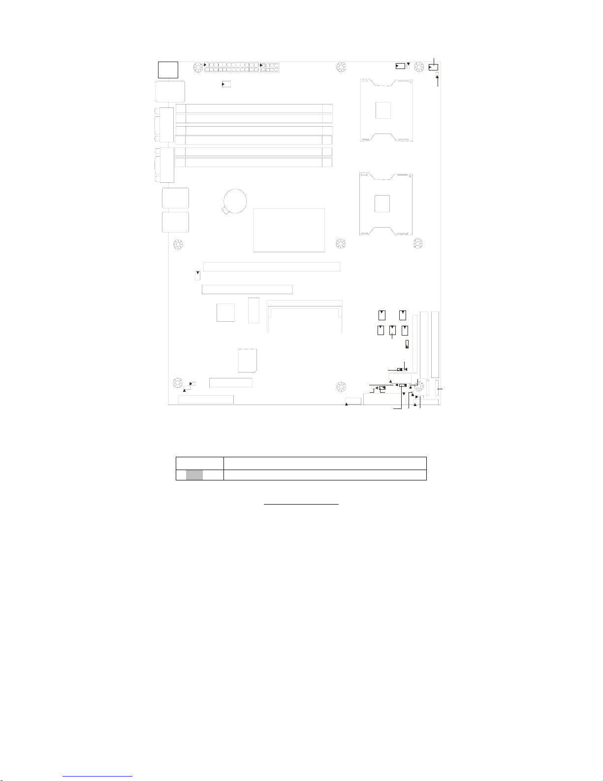
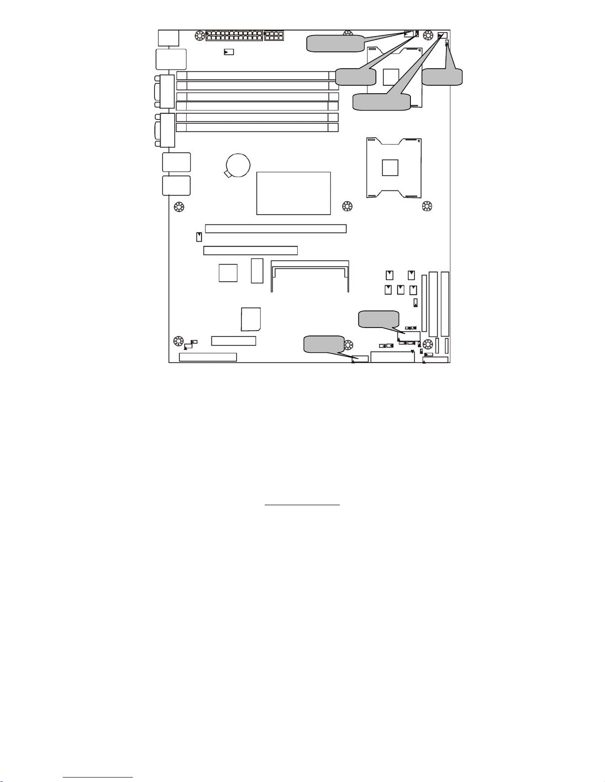
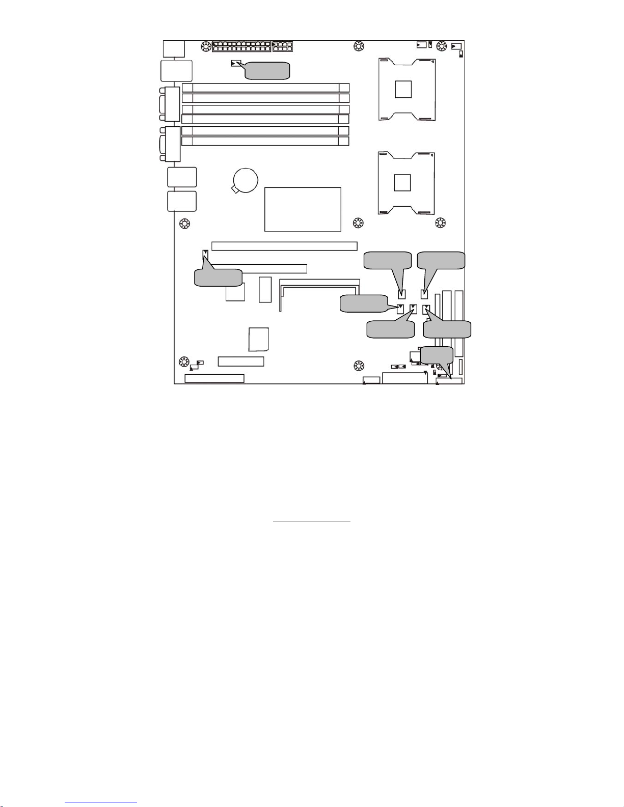
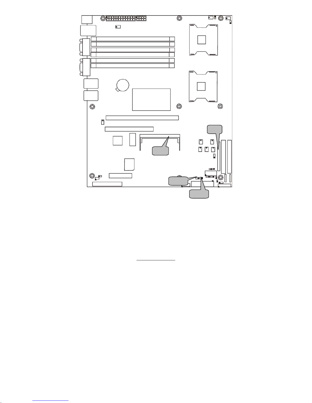
2.3 - Board Parts, Jumpers and Connectors
PW1
PW2
JP 44
CPUFAN1
FA N 7
CPUFAN2
JP4 3
CPU2
CPU1
LAN2
LAN1
PCI -1
COM
VGA
LAN3
U SB x 2
B_DIMM1
A_DIMM1
B_DIMM2
A_DIMM2
B_DIMM3
A_DIMM3
J23
JP2
FD D1
PCI-E1 (x4)
SO-DIMM Socket
FAN6
PCIX-P1
IDE1
SATA1
COM2
FAN 4
LPT
IDE2
J19 (SMDC)
SATA2
JP11
J20
FAN 5
FAN1
FA N 2
FAN 3
JP22
JP 27
JP20
JP13
JP 29
JP18
JP26
JP14
JP21
JP23
KB/ MS
This diagram is representative of the latest board revision available at the time of
publishing. The board you receive may not look exactly like the above diagram.
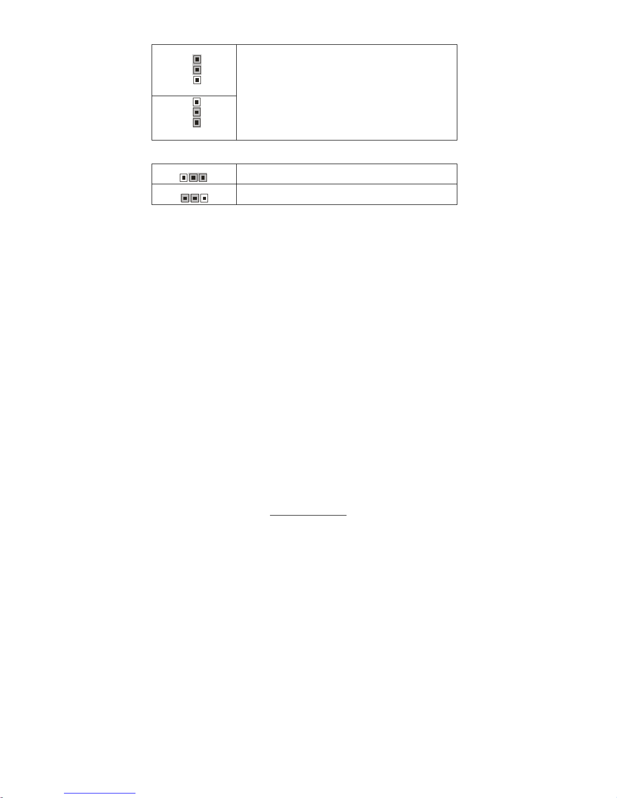
Jumper Legend
OPEN - Jumper OFF, without jumper cover
CLOSED – Jumper ON, with jumper cover
http://www.tyan.com
11
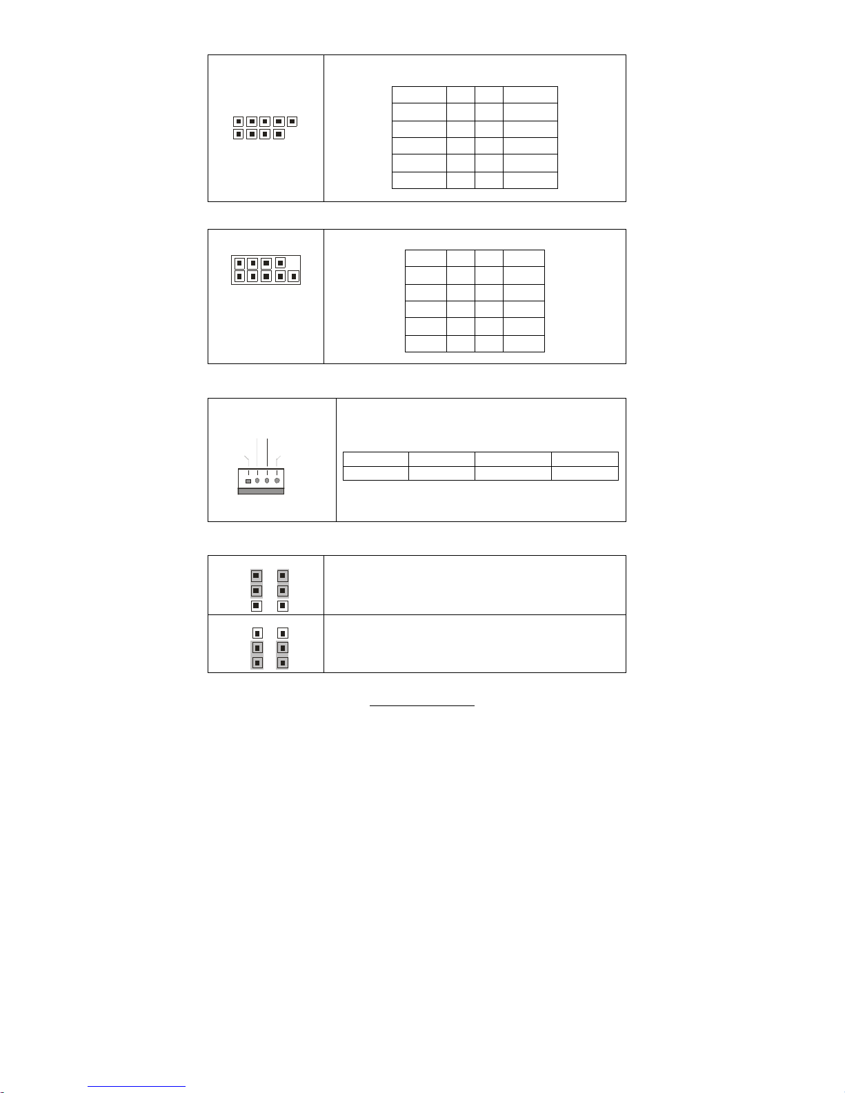
Jumper/Connector Function
FAN6/FAN7 3-pin Chassis Fan Connector
CPUFAN1/CPUFAN2 4-pin CPU Fan Connector
JP43/JP44
CPU Fan Support 4-pin or 3-pin Select Jumper
(Close 1-2) Default support 3-pin
(Close 2-3) support 4-pin
FAN1~FAN5 3-pin System Fan Connector
JP16 COM2 Connector
JP11 USB Front Panel Connector
J20 Front Panel Header
J19 SMDC Connector
JP13 External HDD LED Header
JP14 SATA LED Header
JP2
External Speaker Connector
(Close 3-4) Default, Buzzer
JP29 3-pin Power LED Connector
JP18/JP21 BCM5721 External LAN1 Connector
JP26/JP27 BCM5705 External LAN2 Connector
JP20/JP23
SMDC/ASF2.0 Select Jumper
(Close 1-2) Default, support ASF 2.0
(Close 2-3) support SMDC card
JP22
Clear CMOS Jumper
(Close 1-2) Default
(Close 2-3) Clear CMOS
J16 SO-DIMM Socket
J23 Reserved for OEM only
http://www.tyan.com
12
CPUFAN1
JP16
JP44
CPUFAN2
JP43
JP11
http://www.tyan.com
13
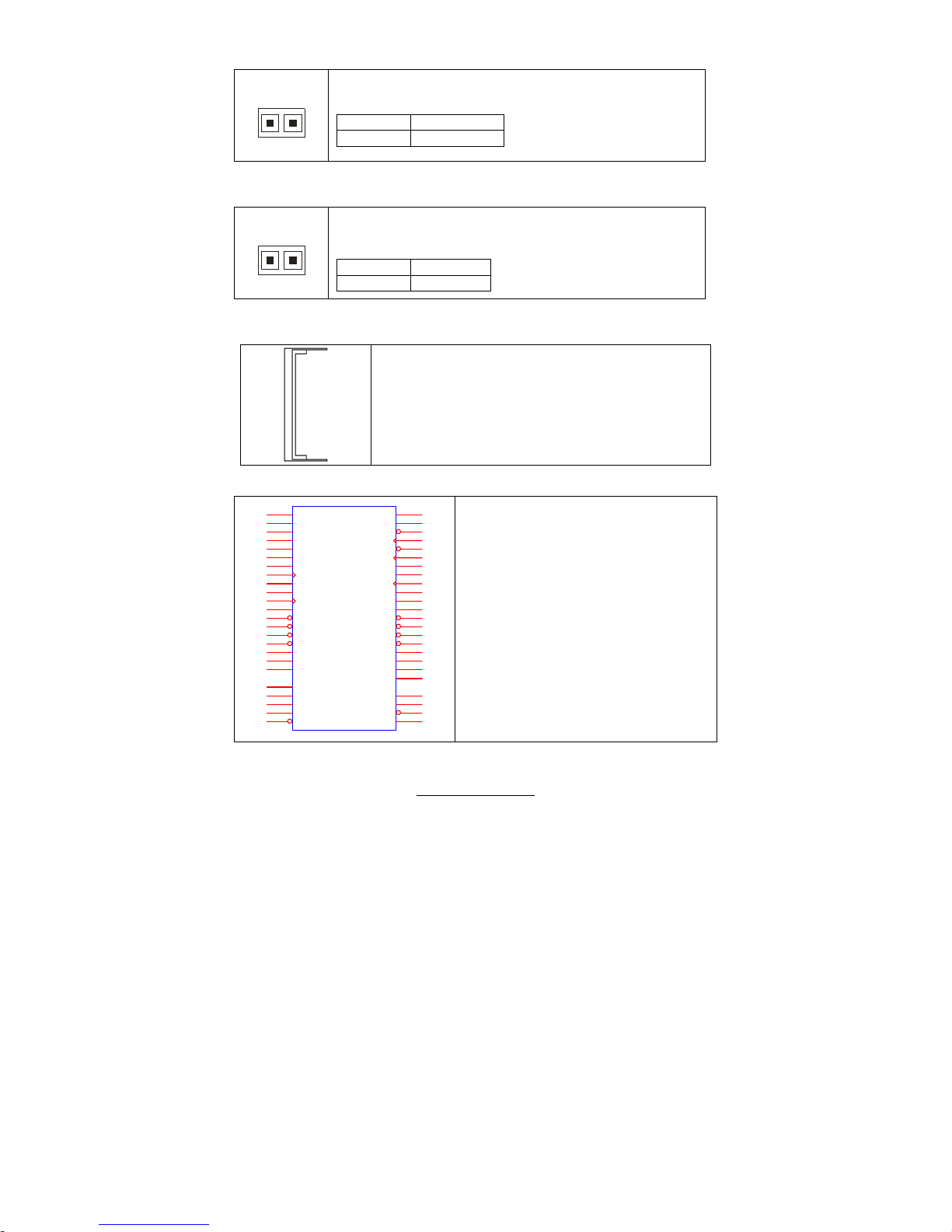
JP11: USB Front Panel Header
1 9
2 10
Use this header to connect to front panel USB
connector.
Signal Pin Pin Signal
USBPWR 1 2 USBPWR
USB_2D- 3 4 USB_3D-
USB_2D+ 5 6 USB_3D+
GND 7 8 GND
KEY 9 10 NC
JP16: COM2 Connector
1 9
2 10
Use these pin definitions to connect a port to COM2.
Signal Pin Pin Signal
DCD 1 2 DSR
RXD 3 4 RTS
TXD 5 6 CTS
DTR 7 8 RI
GND 9 10 KEY
CPUFAN1/CPUFAN2: CPU Fan Support 4-pin Connector
PWM
Fan PWM
GND
TACH
Use these headers to connect the cooling fans to the
motherboard to keep the system stable and reliable.
JP12: CPUFAN1 JP31: CPUFAN2
Pin 1 Pin 2 Pin 3 Pin 4
GND PWM TACH Fan PWM
JP43/JP44: CPU Fan Support 4-pin or 3-Pin Select Jumper
JP43 JP44
131
3
Use the default setting if the CPU fan has a 3-pin fan
power connector.
JP43 JP44
131
3
Select this setting if the CPU fan has a 4-pin fan power
connector.
http://www.tyan.com
14
J20
FAN7
FAN6
FAN1 FAN2
FAN5 FAN4
FAN3
http://www.tyan.com
15
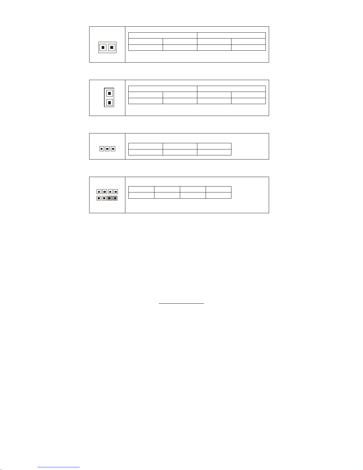
FAN6/FAN7: 3-pin Fan Connector
+12V
GN
D
NC
1
Use these headers to connect the cooling fans to the
motherboard to keep the system stable and reliable.
JP3: FAN6 JP7: FAN7
FAN1/FAN2/FAN3/FAN4/FAN5: 3-pin Fan Connector with Speed Control
+12V
GN
D
TACH
1
Use these headers to connect the cooling fans to the
motherboard to monitor their fan speeds to keep the
system stable and reliable.
JP15: FAN1 JP17: FAN2 JP19: FAN3
JP24: FAN4 JP28: FAN5
J20: Front Panel Header
The motherboard provides one front panel header for electrical connection to
the front panel switches and LED’s.
PWR LED+
PWR LED-
PWR SW#
GND
Warning LED+
Warning LED-
_
GND
Chassis Intrusion #
2 4 6 8 10 12 14 16 18
1 3 5 7 9 11 13 15 17
HDD LED+
HDD LED-
GND
Reset
+5V
Ext. Interrupt
+5VSB
SMBUS Data
SMBUS Clock
http://www.tyan.com
16
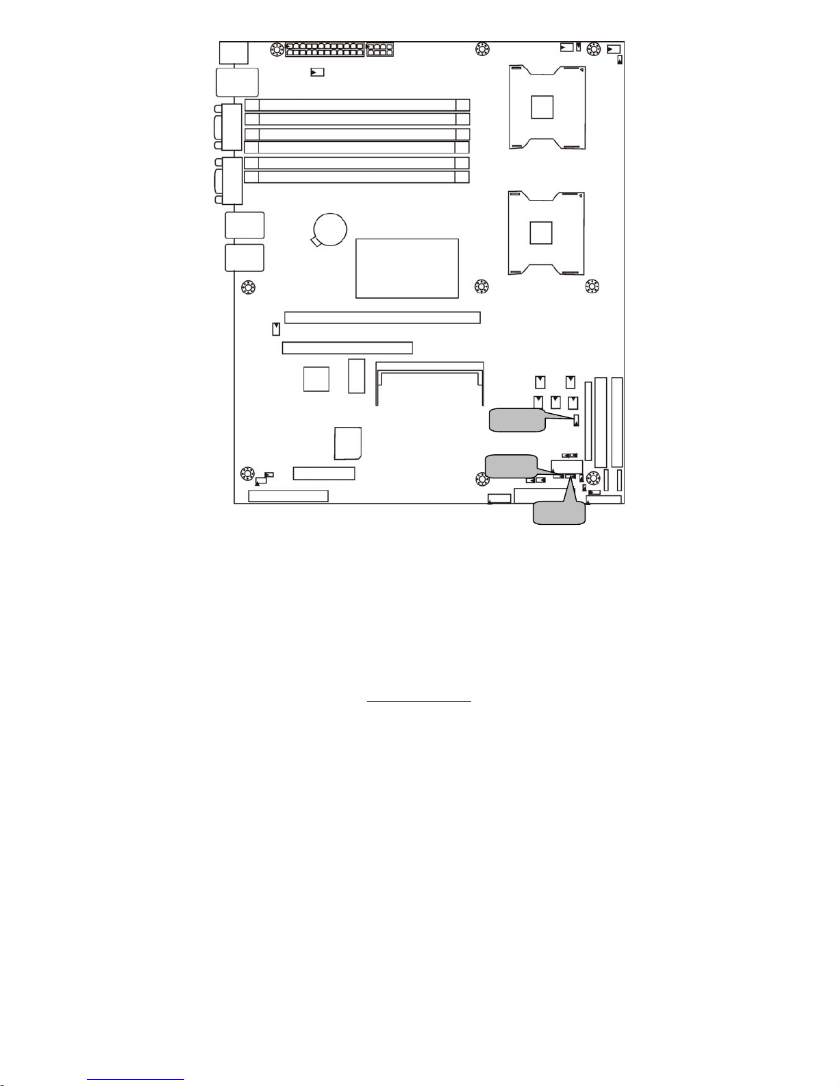
JP13
J19
J16
JP14
http://www.tyan.com
17
JP13: External HDD LED Connector
1
Use this header to connect for external HDD LED’s.
Pin 1 Pin 2
GND EXT_HDLED
JP14: SATA LED Connector
1
Use this header to connect SATA LED’s to indicate the status
of the SATA RAID.
Pin 1 Pin 2
3.3V SATALED-
J16: SO-DIMM Socket
Connect SAS/SATA II Daughter Card (compatible with
Tyan M9000-10, M7901/7902 Ultra 320 SCSI “TARO”
card).
J19: SMDC Connector
J19
HDR25X2_SVM_A
LAD0
1
LAD2
3
GND1
5
GND2
7
GND3
9
GND4
11
I2C1DA
13
I2C4CLK
15
GND6
17
I2C3DA
19
I2C2CLK
21
5VSB2
23
PWRBTN#
25
RS TBTN#
27
SLPBTN#
29
EXTSMI#
31
CPUNMI
33
GPIO1
35
GND9
37
GND10
41
RSVD3
43
RSVD5
45
GND12
47
SMALERTB#
49
LAD1
2
LAD3
4
LFRAME#
6
PCI_C LK
8
PCIR ST#
10
I2C1CLK
12
GND5
14
I2C4DA
16
I2C3CLK
18
5VSB1
20
I2C2DA
22
GND7
24
PCIPME#
26
SVM_IRQ#
28
SVM_WOL#
30
SVM_ THER M#
32
GND8
34
GPIO2
36
GPIO4
38
PS_PWRGD
40
GND11
44
RSVD6
46
SMALERTA#
48
GND13
50
For connection with Tyan Server
Management Daughter Card (SMDC).
The SMDC connector is compatible with
Tyan M3291 SMDC.

http://www.tyan.com
18
JP27
JP21
JP2
JP29
JP26
JP18
http://www.tyan.com
19
JP18/JP21: BCM5721 External LAN1 Connector
1
JP18 (Link/Activity) JP21 (10/100/1GM)
Pin 1 Pin 2 Pin 1 Pin 2
3.3VSB LAN1_ACT- 1000M+ 100M+
JP26/JP27: BCM5705 External LAN2 Connector
1
JP27 (Link/Activity) JP26 (10/100/1GM)
Pin 1 Pin 2 Pin 1 Pin 2
3.3VSB LAN2_ACT- 1000M+ 100M+
JP29: 3-pin Power LED Header
31
Pin 1 Pin 2 Pin 3
PWRLED+ NC GND
JP2: External Speaker Header
41
4
1
Close Pin 3-4: Buzzer (Default)
Pin 1 Pin 2 Pin 3 Pin 4
VCC NC INTSP SPK3
http://www.tyan.com
20
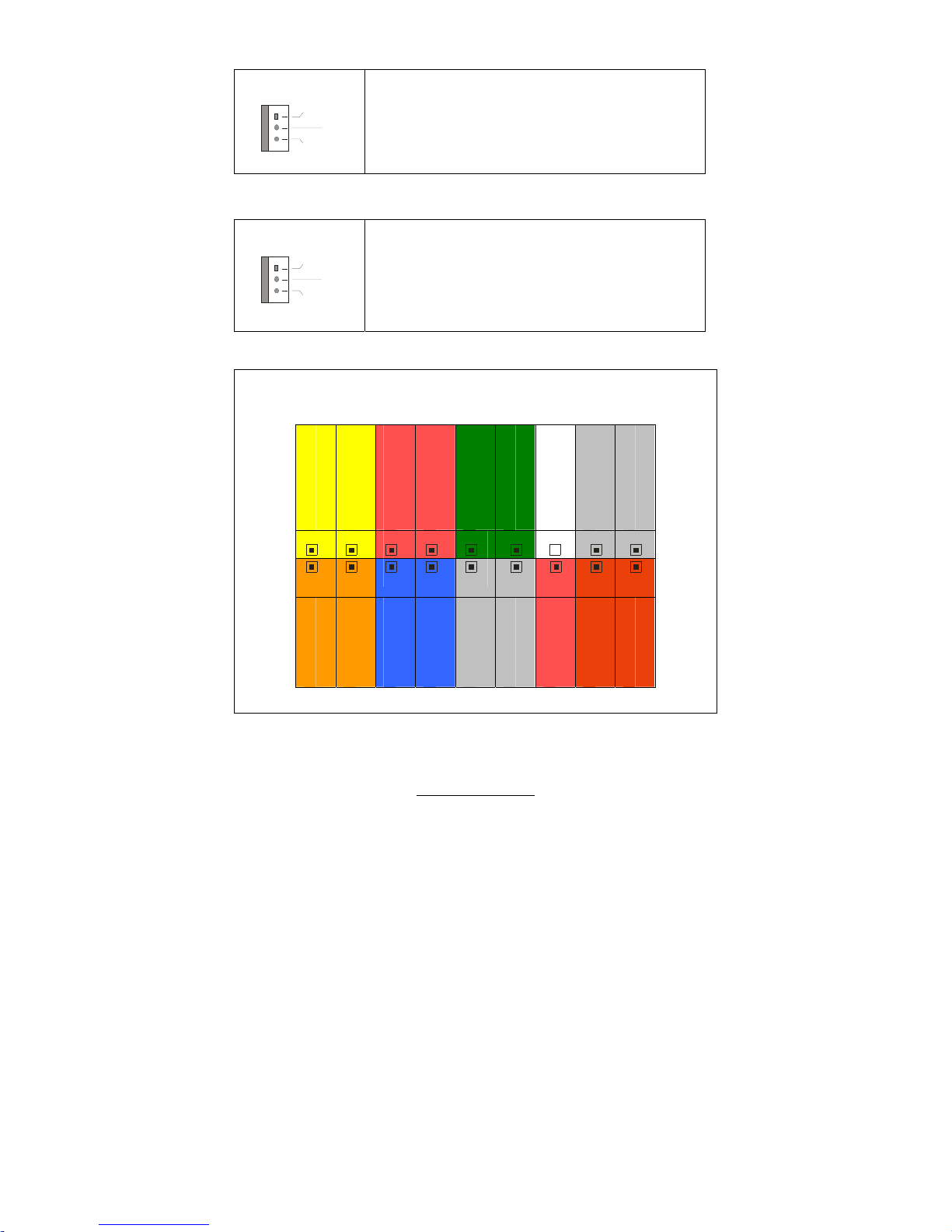
JP22
JP23
JP20
http://www.tyan.com
21
JP22: Clear CMOS Jumper
JP20/JP23: SMDC/ASF2.0 Select Jumper
3
1
(Clear)
3
1
(Default)
You can reset CMOS settings by using this jumper if
you have lost your system/setup password or need to
clear the system BIOS settings.
Power off the system and set JP22 to (2-3) position,
and then power on the system. The CMOS will be
cleared when the POST screen is visible. Finally shut
down the power and move JP22 to it’s default (1-2)
position and power on the system again.
1
3
Support ASF2.0, only applies to LAN1 (5721)
3
1
Supports M3291 SMDC card which only applies to
LAN3 (82551)
http://www.tyan.com
22
2.4 – Mounting the Motherboard
Before installing your motherboard, make sure your chassis has the
necessary motherboard support studs installed. These studs are usually
metal and are gold in color. Usually, the chassis manufacturer will pre-install
the support studs. If you are unsure of stud placement, simply lay the
motherboard inside the chassis and align the screw holes of the
motherboard to the studs inside the case. If there are any studs missing,
you will know right away since the motherboard will not be able to be
securely installed.
Pay attention when installing board in chassis. Some components are
near the mounting holes and can be damaged.
Some chassis’ include plastic studs instead of metal. Although the plastic
studs are usable, TYAN recommends using metal studs with screws that will
fasten the motherboard more securely in place.
Below is a chart detailing what the most common motherboard studs look
like and how they should be installed.
http://www.tyan.com
23
2.5 - Installing the Memory
Before attempting to install any memory, make sure that the memory you
have is compatible with the motherboard as well as the processor.
The following diagram shows common types of DDR2 memory modules.
.
Key points to note before installing memory into Tiger i7322DP:
For optimal dual-channel DDR operation, always install memory in pairs
beginning with A_DIMM1 and B_DIMM1. Memory modules of the same
type and density are required for dual-channel DDR operation. Mismatched
memory may cause system instability.
Refer to the following table for supported DDR2 populations.
Option 1 Option 2 Option 3
A_DIMM1 Install Install Install
B_DIMM1 Install Install Install
A_DIMM2 X Install Install
B_DIMM2 X Install Install
A_DIMM3 X X Install
B_DIMM3 X X Install
128MB, 256MB, 512MB, 1GB, 2GB Registered ECC DDR2-400 SDRAM
memory modules are supported. All installed memory will be automatically
detected. The Tiger i7322DP S5353 supports up to 16GB of memory.
http://www.tyan.com
24
Memory Installation Procedure
Follow these instructions to install memory modules into the Tiger i7322DP
S5353.
1. Press the locking levers in the direction shown in the following illustration.
2. Align the memory module with the socket. The memory module is keyed
to fit only one way in the socket.
3. Seat the module firmly into the socket by gently pressing down until it sits
flush with the socket. The locking levers pop up into place.
Key slot
http://www.tyan.com
25
2.6 - Installing the Processor and Cooling Fan
Your Tiger i7322 S5353 supports the latest processor technologies from Intel.
Check the TYAN website for latest processor support:
http://www.tyan.com
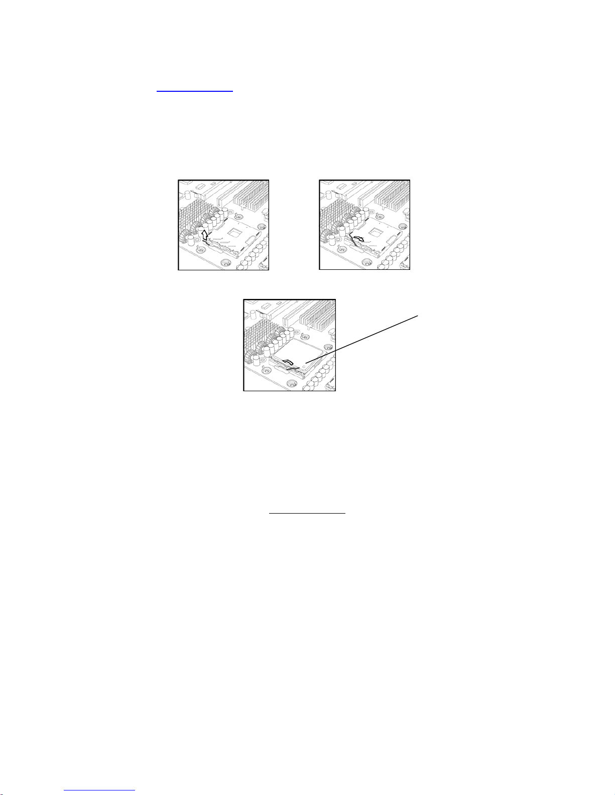
Processor Installation
The processor should be installed carefully. Make sure you are wearing an
antistatic strap and handle the processor as little as possible.
Follow these instructions to install your processor and heat sink.
1. Locate the processor sockets on the motherboard and lift the locking lever
as shown.
2. Insert the processor into the socket making sure that pin 1 is correctly
located.
3. Return the locking lever to its locked position.
4. Repeat this procedure for the second processor socket.
5. Turn the board upside down and insert the heat sink spring mechanism
as shown.
http://www.tyan.com
26
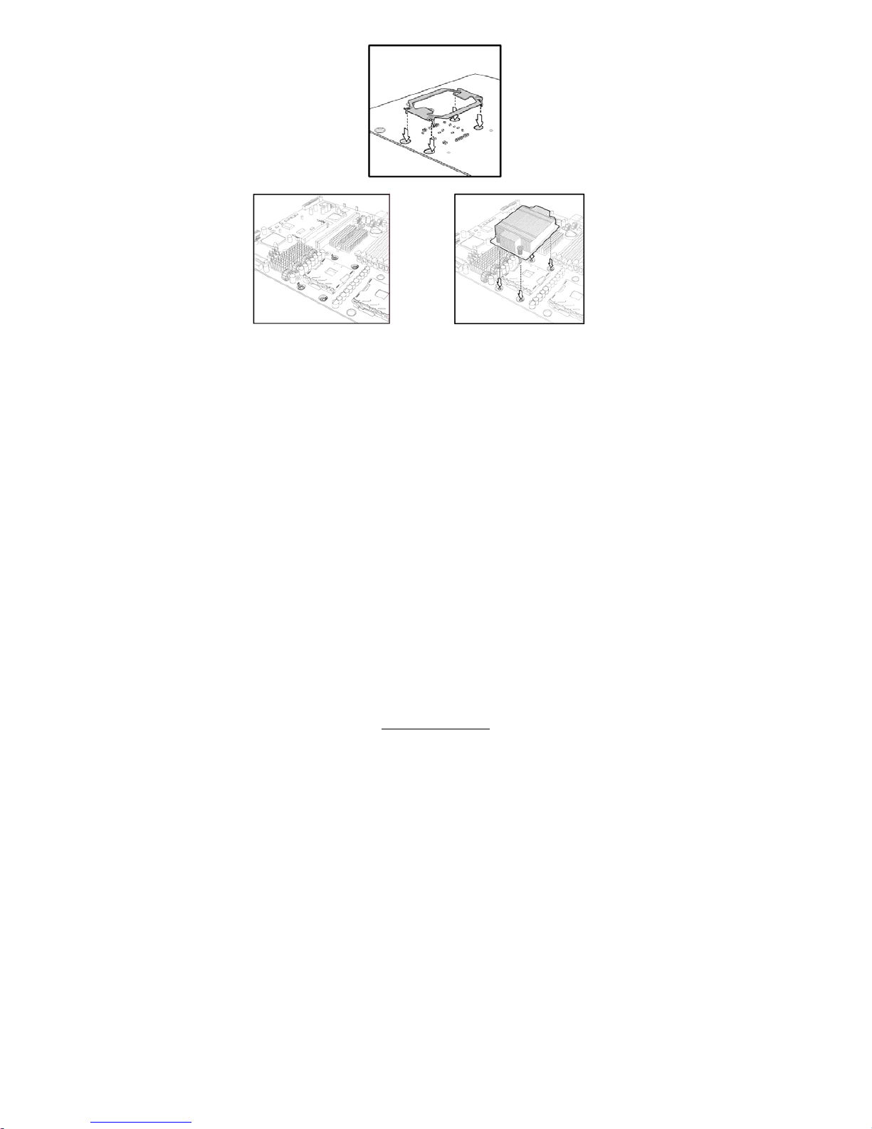
6. Turn the board the right way up again and screw the heat sink into place.
7. Repeat this procedure for the second processor.
Cooling Fan Installation
After you have installed the processor, the heatsink should be installed to
ensure that the processor runs efficiently and does not overheat. Use the
heatsink supplied for best results.
Follow these instructions to install the heatsink shown.
1. Apply some (a little will work, more doesn’t equal better performance)
thermal compound to the top of the processor. Try and apply a thin, even
layer over the top of the processor.
2. Align the heatsink with the four holes around the processor socket.
3. Press the heatsink down until the four screws are securely seated in the
holes.
4. Use screw drive to secure the four screws.
http://www.tyan.com
27
2.10 - Attaching Drive Cables
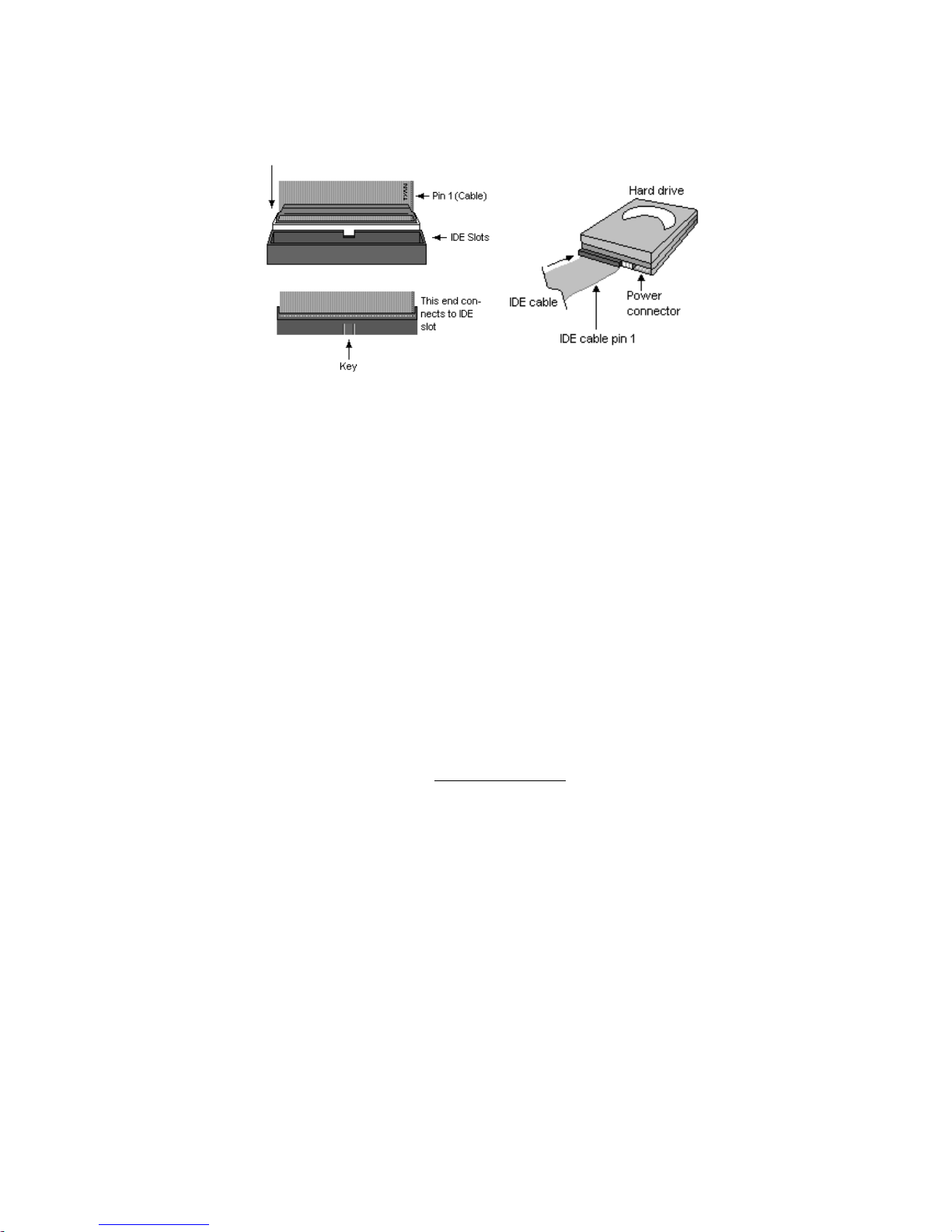
Attaching IDE Drive Cable
Attaching the IDE drive cable is simple. The cable is “keyed” to only allow it
to be connected in the correct manner.
Attaching IDE cable to the IDE connector is illustrated below:
Simply plug in the BLUE END of the IDE cable into the motherboard IDE
connector and the other end into the IDE device itself. Each standard IDE
cable has three connectors, two of which are closer together. The BLUE
connector that is furthest away from the other two connectors. The other two
connectors are used to connect additional IDE devices.
Note: Always remember to properly set the drive jumpers. If only using one
device on a channel, it must be set as Master for the BIOS to detect it
properly.
TIP: Pin 1 on the IDE cable (usually designated by a colored wire)
faces the drive’s power connector.
Attaching Serial ATA Cables
The Tiger i7322DP is also equipped with 4 Serial ATA (SATA) channels.
Connections for these drives are also very simple.
There is no need to set Master/Slave jumpers on SATA drives.
 Loading...