

TYAN TIGER I7320, D, R, RD, Tiger i7320R User Manual
...
Tiger i7320 / Tiger i7320R User’s Manual
i
http://www.tyan.com
Tiger i7320 / i7320R
///
S5350 / S5350-1U
Revision 1.01
Copyright © TYAN Computer Corporation, 2004. All rights reserved. No part of this manual
may be reproduced or translated without prior written consent from TYAN Computer Corp.
All registered and unregistered trademarks and company names contained in this manual are
property of their respective owners including, but not limited to the following.
TYAN, Tiger i7320 S5350 / Tiger i7320R S5350-1U are trademarks of TYAN Computer
Corporation.
Intel, Nocona and combinations thereof are trademarks of Intel Corporation.
Phoenix, PhoenixBIOS are trademarks of Phoenix Technologies Ltd.
Microsoft and Windows are trademarks of Microsoft Corporation.
IBM, PC, AT and PS/2 are trademarks of IBM Corporation.
Adaptec is a trademark of Adaptec Inc.
ATI, ATI RAGE is a trademark of ATI Technologies Incorporated.
Winbond is a trademark of Winbond Electronics Corporation
SMSC is a trademark of Standard Microsystems Corporation.
Broadcom is a trademark of Broadcom Corporation.
Portable Document Format (PDF) is a trademark of Adobe Corporation.
Information contained in this document is furnished by TYAN Computer Corporation and has
been reviewed for accuracy and reliability prior to printing. TYAN assumes no liability
whatsoever, and disclaims any express or implied warranty, relating to sale and/or use of
TYAN products including liability or warranties relating to fitness for a particular purpose or
merchantability. TYAN retains the right to make changes to product descriptions and/or
specifications at any time, without notice. In no event will TYAN be held liable for any direct or
indirect, incidental or consequential damage, loss of use, loss of data or other malady resulting
from errors or inaccuracies of information contained in this document.

Tiger i7320 / Tiger i7320R Table of Contents
ii
http://www.tyan.com
Table of Contents
Before you begin… ................................................................................................................. iv
Chapter 1: Introduction.........................................................................................................1-1
1.1 Congratulations! ......................................................................................................... 1-1
1.2 Hardware Specifications ............................................................................................ 1-1
Chapter 2: Board Installation ............................................................................................... 2-1
2.1 Installing the Motherboard ......................................................................................... 2-1
2.1.1 Installation Notes ............................................................................................. 2-1
2.2 Board Image .............................................................................................................. 2-2
2.3 Block Diagram............................................................................................................ 2-4
2.4 Motherboard Components ......................................................................................... 2-5
2.5 Jumpers and Connectors ........................................................................................... 2-6
2.5.1 Jumper Legend ................................................................................................ 2-7
2.5.2 SO-DIMM Socket: J19 (for Tiger i7320R S5350-1U only)).............................. 2-7
2.5.3 SMDC Connector: J21 (Optional) .................................................................... 2-7
2.5.4 Front Panel Connector: J22 ............................................................................. 2-8
2.5.5 External speaker Header: JP4 ......................................................................... 2-8
2.5.6 Chassis Fan Connectors with Fan Control: FAN 1/2/3/4/5 .............................. 2-9
2.5.7 Front Panel USB 2.0 Connector: JP13 (USB2) ............................................... 2-9
2.5.8 CPU FAN1/FAN2 Connectors ....................................................................... 2-10
2.5.9 SATA activity LED Header: JP16 .................................................................. 2-10
2.5.10 Chassis Fan Connectors: FAN6, FAN7 ....................................................... 2-11
2.5.11 COM2 connector: JP18 ............................................................................... 2-11
2.5.12 LAN1/LAN2 activity LED Headers: JP21, JP30........................................... 2-12
2.5.13 LAN1/LAN2 speed LED Headers: JP24, JP29 ............................................ 2-12
2.5.14 Clear CMOS Jumper: JP25 ......................................................................... 2-13
2.5.15 3-pin Power LED Connector: JP32 .............................................................. 2-13
2.6 Mounting the Motherboard ....................................................................................... 2-14
2.6.1 Installing Memory........................................................................................... 2-15
2.6.2 Memory Installation Procedure ...................................................................... 2-16
2.6.3 Installing the Processor and Cooling Fan ...................................................... 2-16
2.7 Installing Drive Cables ............................................................................................. 2-18
2.8 Installing Expansion Cards ...................................................................................... 2-19
2.9 Installing Optional SO-DIMM modules (for S5350-1U only) .................................... 2-20
2.10 Connecting External Devices ................................................................................. 2-21
2.10.1 Onboard LAN LED Color Definition ............................................................. 2-21
2.11 Installing the Power Supply.................................................................................... 2-22
2.12 Finishing Up ........................................................................................................... 2-22
Chapter 3: BIOS Setup.......................................................................................................... 3-1
3.1 About the BIOS .......................................................................................................... 3-1
3.2 Main BIOS Setup ....................................................................................................... 3-2
3.3 Main ........................................................................................................................... 3-3
3.3.1 IDE Master / Slave Setup ................................................................................ 3-4
3.3.2 Memory Cache................................................................................................. 3-6
3.3.3 Boot Features .................................................................................................. 3-7
3.4 Advanced ...................................................................................................................3-8
3.4.1 Hardware Monitor .......................................................................................... 3-10
3.4.2 Advanced Chipset Control ............................................................................. 3-10
3.4.3 Advanced Processor Options ........................................................................ 3-13
3.4.4 I/O Device Configuration................................................................................ 3-14
3.4.5 DMA Event Logging ....................................................................................... 3-17
3.4.6 Console Redirection ...................................................................................... 3-18
3.4.7 ASF Configuration ......................................................................................... 3-19

Tiger i7320 / Tiger i7320R Table of Contents
iii
http://www.tyan.com
3.5 Security ....................................................................................................................3-20
3.6 Power .......................................................................................................................3-21
3.7 Boot.......................................................................................................................... 3-22
3.8 Exit ........................................................................................................................... 3-22
Chapter 4: SATA/RAID Setup (for SATA RAID model) ...................................................... 4-1
4.1 BIOS Configuration .................................................................................................... 4-1
4.2 Installing Serial ATA (SATA) hard disks .................................................................... 4-1
4.3 Adaptec RAID Configuration Utility ............................................................................ 4-2
4.4 Manage Array ............................................................................................................ 4-2
4.5 Create Array...............................................................................................................4-3
4.6 Add/Delete Hotspare.................................................................................................. 4-5
4.7 Initialize Drives ...........................................................................................................4-6
4.8 Disk Utilities................................................................................................................4-7
Chapter 5: Diagnostics ......................................................................................................... 5-1
5.1 Beep Codes ............................................................................................................... 5-1
5.2 Flash Utility.................................................................................................................5-1
Appendix I: Glossary ............................................................................................................6-1
Technical Support ............................................................................................................ 6-7
Tiger i7320 / Tiger i7320R Before you begin…
iv
http://www.tyan.com
Before you begin…
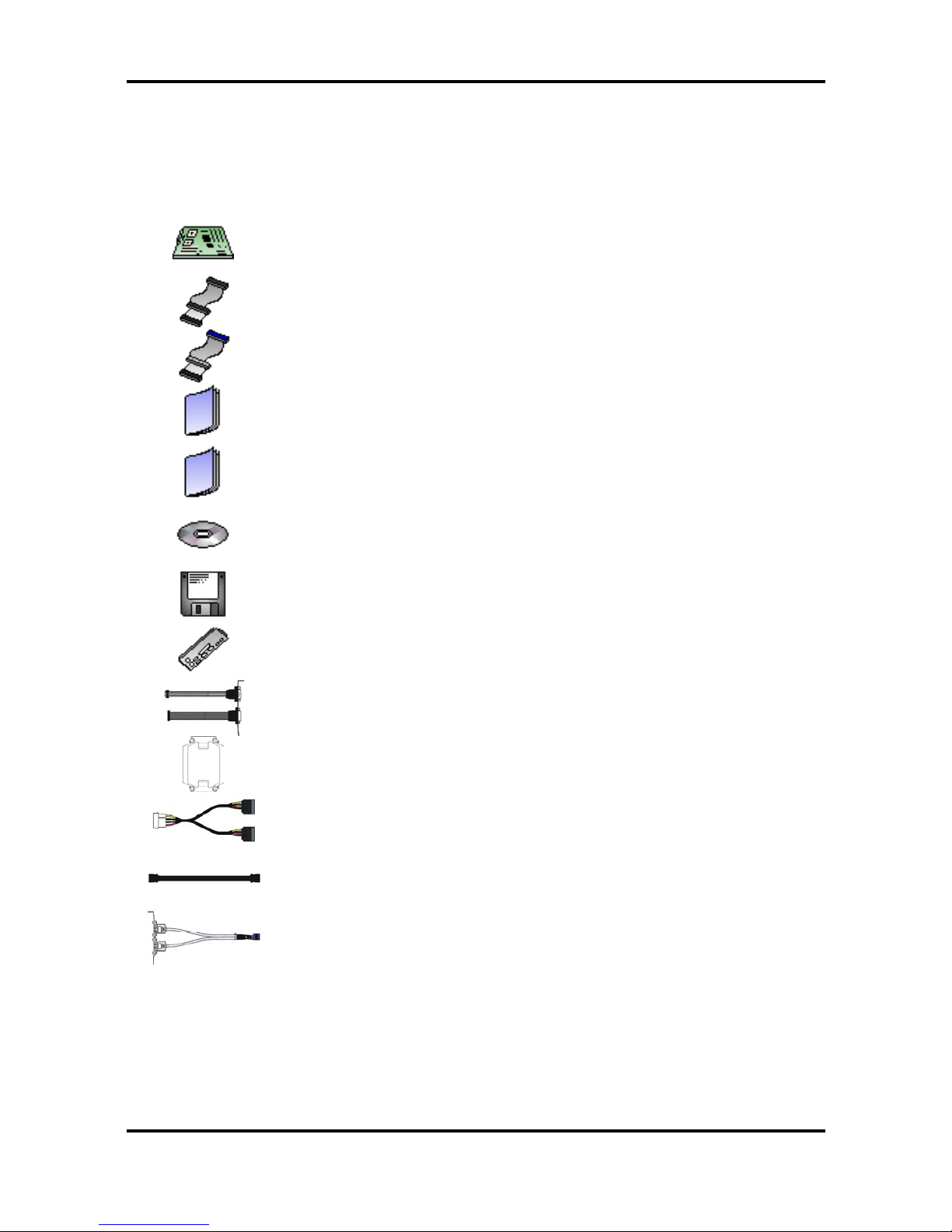
Check the package contents before you proceed.
The retail motherboard package should contain the following:
1 x motherboard
1 x 34-Pin floppy drive cable
2 x Ultra-DMA-133/100/66/33 IDE cable
1 x User’s Manual
1 x Quick Reference Guide
1 x TYAN driver CD
1 x SATA RAID Driver Diskette
1 x I/O shield
1 x Cable set (9 pin serial and 24 pin parallel )
2 x CEK Spring
1 x Serial ATA power cable
2 x Serial ATA cable
1 x USB2.0 cable
If any of these items are missing, please contact your vendor or dealer for replacement before
continuing with the installation process.

Tiger i7320 / Tiger i7320R Chapter 1: Introduction
1-1
http://www.tyan.com
Chapter 1: Introduction
1.1 Congratulations!
Congratulations on your purchase of the powerful Dual Intel Xeon processor solution, the
Tiger i7320 S5350 / Tiger i7320R S5350-1U. Based on Intel E7320 chipset, the S5350 offers
exceptional performance. Compatible with EPS12V power supplies, the CEB form factor
S5350 features an onboard ATi 8MB PCI RageXL VGA, two Gigabit Ethernet ports, serial ATA,
RAID, which provides an advances and versatile solution for your server needs.
For more information about this and other TYAN products, visit the TYAN Web site at
http://www.tyan.com. Product FAQs, distributors list and advanced BIOS information are also
available on the Web site.
1.2 Hardware Specifications
Processors
• Two mPGA604 sockets
•
Intel® Xeon “Nocona” processor with
EM64T support
• 800 MHz FSB support
Expansion Slots
• Tiger i7320 (S5350)
- Two PCI-X 64/66 slots
- Three 32/33 PCI 2.3 slots
• Tiger i7320R (S5350-1U)
- One PCI-X 64/66 slot
- One propriety TARO® SO-DIMM
connector
Chipset
• Intel E7320 (“Lindenhurst-VS”) MCH
• Intel 6300ESB (“Hance Rapids”) South
Bridge
• SMSC DME1737 LPC I/O chip
System Management
• SMSC DME1737 and EMC6D102 (or
ADM1027) w/ hardware monitoring
•
Nine 3-pin Fan headers (seven w/
tachometer input and temperature-sensing
auto fan control)
• Temperature and voltage monitoring
•
Watchdog timer
Integrated LAN Controllers
• Two GbE LAN controllers
Two Broadcom BCM5721 PCIExpress GbE Lan controller
WoL and Teaming supported
Integrated 2D/3D PCI Graphics
• ATI® Rage
TM
XL PCI graphics
controller
• 8MB frame buffer of video memory
Optional Modules
• M3289, IPMI SMDC card
QLogic Zircon BMC
Tailored for IPMI highest 1.5 spec.
Built-in IPMB connector
Supports remote power on/off and
reset
• M7901/M7902, SO-DIMM Ultra 320
SCSI card
Adaptec AIC-7901/7902 single/dual-
channel Ultra 320 SCSI controller
Adaptec HostRAID support w/ RAID
0, 1, 10 supported
• M8110 SO-DIMM SATA card
Adaptec AIC-8110 SATA I controller
Supports up to 4 SATA ports
running at 1.5Gb/s
Adaptec Host RAID support with
RAID 0, 1 & 10 supported

Tiger i7320 / Tiger i7320R Chapter 1: Introduction
1-2
http://www.tyan.com
Memory
• Dual memory channels, 8 x DIMM sockets
•
Supports up to eight DDR-266/333 DIMM
• Registered ECC memory supported
Integrated PCI IDE
• Dual channel master mode support four
IDE devices
• Supports for ATA-100/66/33 IDE drives
and ATAPI compliant devices
Integrated Serial ATA
• Two serial ATA host controllers embedded
• Supports two serial ports running at
1.5Gb/s
• RAID 0 or 1 supported
Back Panel I/O Ports
• Stacked PS/2 mouse & keyboard ports
• Stacked two USB2.0 ports
•
One 15-pin VGA port
• One 9-pin COM port
•
Two RJ45 10/100/1000 Base-T port w/
activity LED
Integrated I/O Interfaces
• One floppy connector
• Two USB 2.0 ports (via cable)
• One COM port (via cable)
• One LPT port (via cable)
•
Power/IDE/SATA LED connectors
• Two 4-pin headers for front panel LAN
LED
• 2 x 25 connector for optional IPMI SMDC
card
BIOS
• Phoenix BIOS 8Mbit Flash
•
Supports APM 1.2 & ACPI 1.0
• PnP, DMI2.0, WfM2.0 power
Management
Form Factor
• CEB footprint
• 10.2" x 12.0” (259.1mm x 304.8mm)
Power
• On board dual 4-phase VRM
• EPS 12V (24-pin + 8-pin) power
connectors
Regulatory
• FCC Class B (Declaration of
Conformity)
• CE (Declaration of Conformity)
• BSMI
Note
TYAN reserves the right to add support or discontinue support for any OS
with or without notice.

Tiger i7320 / Tiger i7320R Chapter 2: Board Installation
2-1
http://www.tyan.com
Chapter 2: Board Installation
2.1 Installing the Motherboard
The Tiger i7320 S5350 / Tiger i7320R S5350-1U motherboard conforms fully to the CEB
specification. Before continuing with the installation, confirm that your chassis supports a
standard CEB motherboard. If you are unsure, contact your dealer for more information.
2.1.1 Installation Notes
This user manual contains important information and you should read it thoroughly before
attempting the installation procedure.
Precautions:
•
Static electricity can damage components on your motherboard. Before
touching the product, discharge any static build up in yourself by touching a
well grounded object such as a metal water pipe or a grounded electrical
appliance. TYAN recommends putting on a good quality grounded wrist strap
before removing your motherboard from the antistatic bag.
•
Disconnect your computer from the power supply before any disassembly
procedure is attempted.
•
Touch the motherboard as little as possible and do not touch the bottom of
the board at all. Bending or flexing the motherboard may break delicate
components or copper tracks on the board.
•
Avoid touching any of the motherboard components.
•
Place the motherboard on a grounded antistatic surface or on the antistatic
bag in which the board was shipped.
•
Inspect the board for damage.
Read the following sections for detailed instructions on how to install your motherboard in a
chassis and add a processor, memory, disk drives, and an optional module.
Warning
Do not apply power to the board if it appears damaged.
Tiger i7320 / Tiger i7320R Chapter 2: Board Installation
2-2
http://www.tyan.com
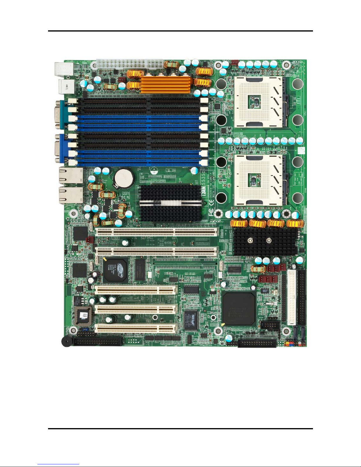
2.2 Board Image
The following is an image of the Tiger i7320 S5350 motherboard.
The above photograph is purely representative. Due to engineering updates and new board
revisions, certain components may change and or be repositioned. The picture above may or
may not look exactly like the board you received.
Tiger i7320 / Tiger i7320R Chapter 2: Board Installation
2-3
http://www.tyan.com
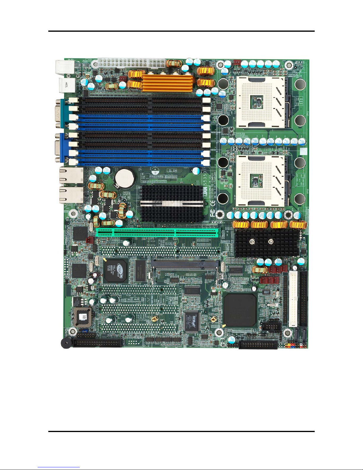
The following is an image of the Tiger i7320R S5350-1U motherboard.
The above photograph is purely representative. Due to engineering updates and new board
revisions, certain components may change and or be repositioned. The picture above may or
may not look exactly like the board you received.
Tiger i7320 / Tiger i7320R Chapter 2: Board Installation
2-4
http://www.tyan.com
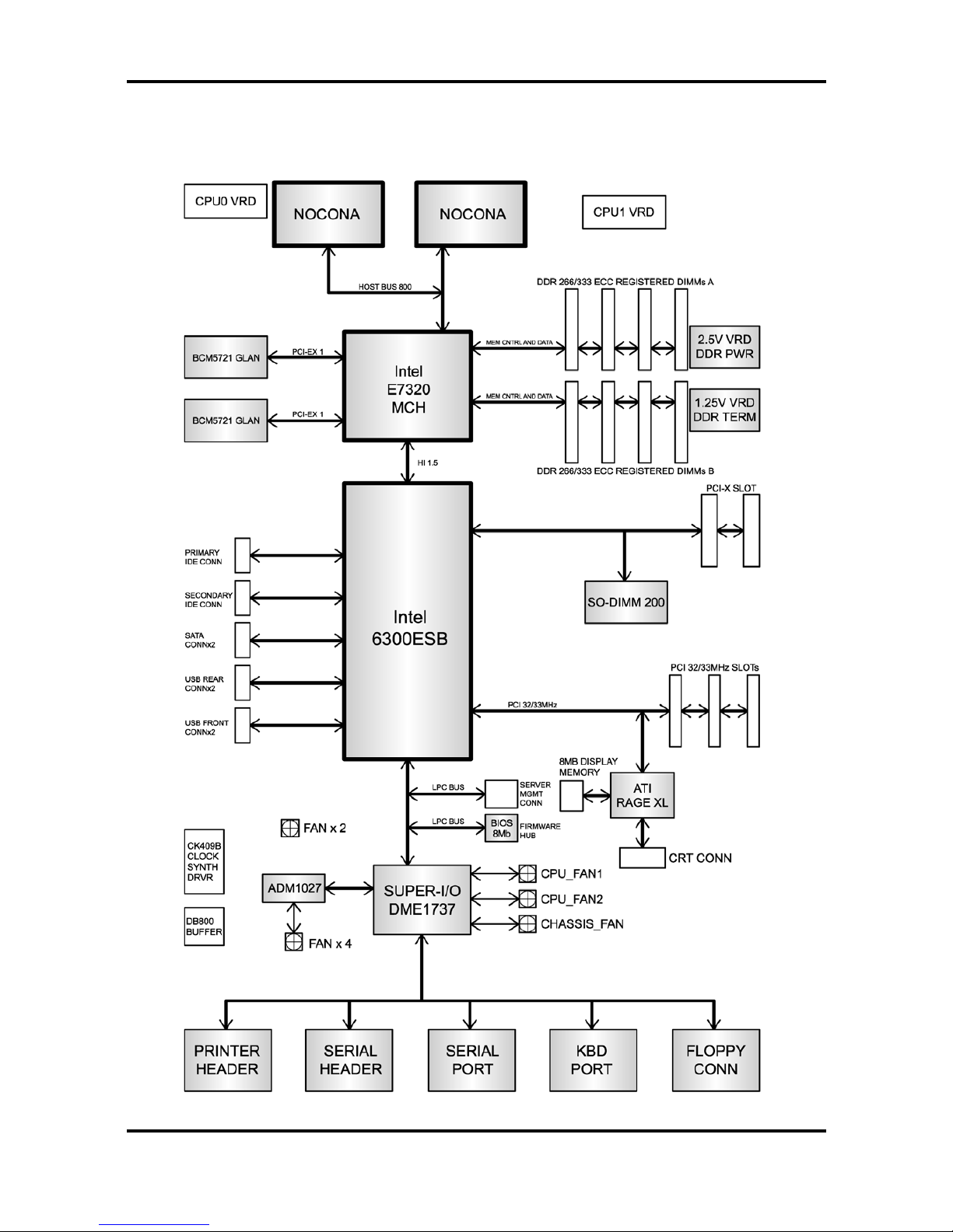
2.3 Block Diagram
The following is a block diagram of the Tiger i7320 S5350 / Tiger i7320R S5350-1U.
Tiger i7320 / Tiger i7320R Chapter 2: Board Installation
2-5
http://www.tyan.com
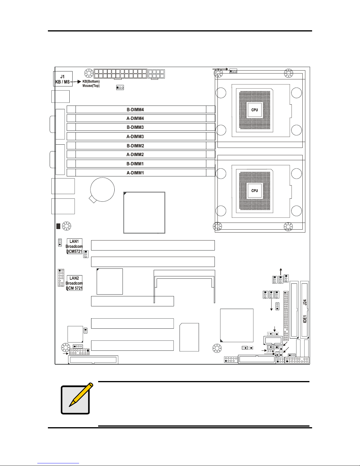
2.4 Motherboard Components
The diagram below shows the main motherboard components.
S5350
1
J4
USB1
J3
(COM1)
J2
(VGA)
CPUFAN1
PW1
LAN1
BIOS
Intel
6300ESB
SATA1
SATA2
FDD1 J5
J22
1
SMSC
DME1737
64-bit 66MHz PCI-X PCIX-P1
LAN2
ATI
RAGE XL
LPT1
USB2
SMDC J21
BATT
64-bit 66MHz PCI-X PCIX-P 2 (Optional)
Intel
E7320
IDE2 J23
PW2
SO_DIMM PCIX-P3 J19(Optional)
1
FAN3
1
FAN7
JP4
1
J36
JP7
1
CPU1
1
FAN2
FAN1
1
CPU2
32-bit 33MHz (5V)PCI PCI-1 (Optional)
32-bit 33MHz (5V)PCI PCI-2 (Optional)
32-bit 33MHz (5V)PCI PCI-3 (Optional)
1
FAN6
1
JP22/27
COM2
JP16
1
JP21
JP24
JP32
LED1
1
JP8
CPUFAN2
FAN5
FAN4
1
JP25
JP30
JP37
1
1
1
JP39
JP18
JP29
JP13
JP15
1
1
JP28
JP1
1
Note
1. This diagram represents the latest version of the motherboard
available at the time of publishing. The board you receive may not look
exactly like the above diagram. Parts are not drawn to scale
2. PCI-1, PCI-2, PCI-3 and PCIX-P2 slots for Tiger i7320 S5350 only.
3. PCIX-P3 (SO_DIMM) socket for Tiger i7320R S5350-1U only.
Tiger i7320 / Tiger i7320R Chapter 2: Board Installation
2-6
http://www.tyan.com
2.5 Jumpers and Connectors
The following section gives details of the motherboard pin headers and jumpers and their
functions. Pin headers are on-board connectors that can be used to connect the motherboard
to peripherals. Jumpers are used to configure the motherboard.
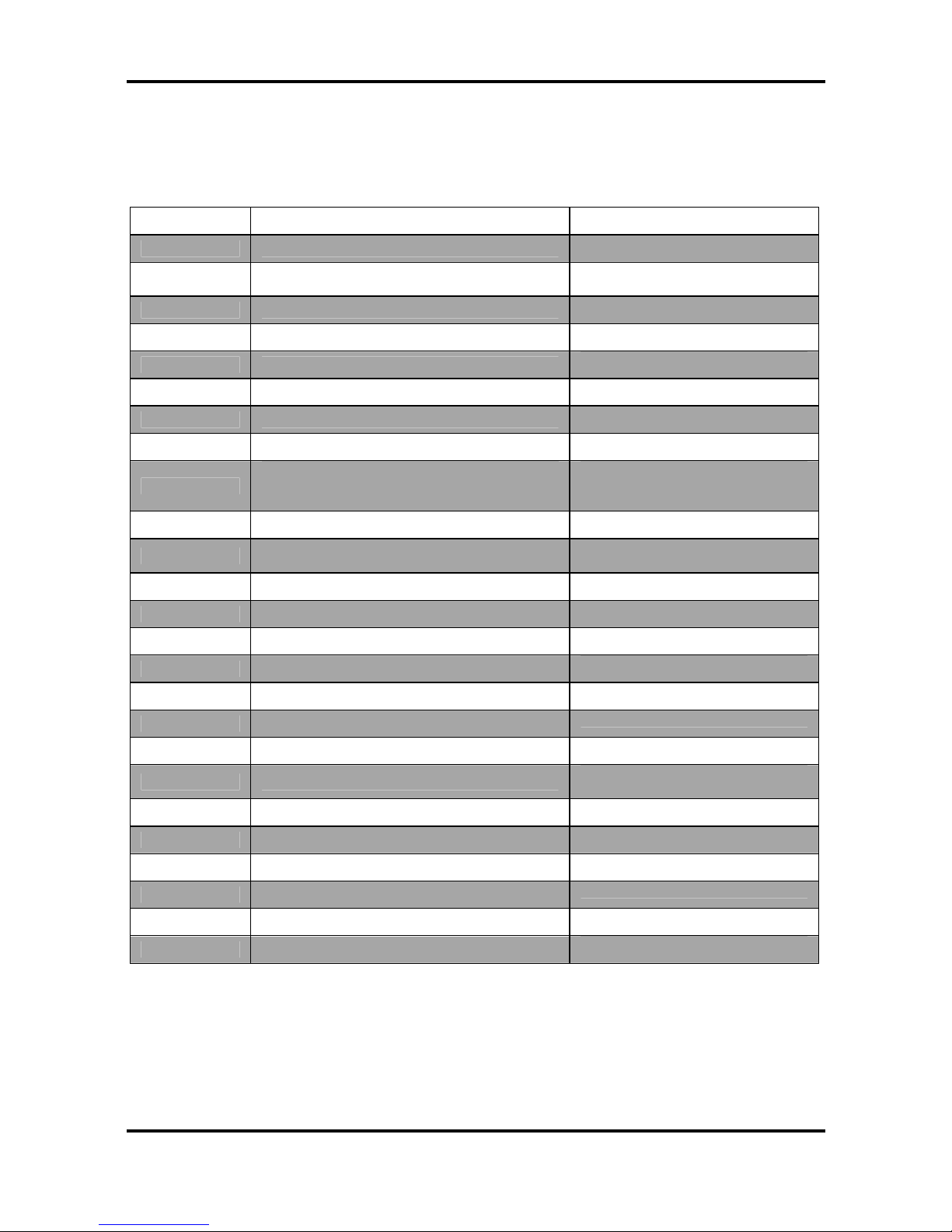
Jumper Function Settings
J19*
SO-DIMM Socket
J21*
SMDC (System Management Daughter
Card) Connector
J22
Front Panel Connector
J36**
Reserved
JP4
External Speaker Header
Pin 3-4 close: Buzzer (Default)
JP1**
Reserved
JP7** Reserved
JP8**
Reserved
FAN1/2/3/4/5
Chassis Fan Connectors with
tachometer monitoring and fan speed
control
JP13 Front Panel USB Header
CPUFAN1/2
CPU Fan Connectors with tachometer
monitoring and fan speed control
JP15**
Reserved
JP16 SATA activity LED Header
FAN6/7
Chassis FAN Connectors
JP18 COM2 Connector
JP21/JP30
LAN1/LAN2 activity LED Headers
JP22**
Reserved
JP24/JP29
LAN1/LAN2 speed LED Headers
JP25 Clear CMOS Jumper
Pin 1-2: Normal (Default)
Pin 2-3: Clear CMOS
JP27**
Reserved
JP28**
Reserved
JP29
LAN2 speed LED header
JP32
3-pin Power LED Connector
JP37**
Reserved
JP39** Reserved
*
Some jumpers and headers are optional and not available with the board due to the different
configurations.
** J36, JP1, JP7, JP8, JP15, JP22, JP27, JP28, JP37, JP39 and Jumpers not listed are reserved for OEM
use or testing purpose only
.
Tiger i7320 / Tiger i7320R Chapter 2: Board Installation
2-7
http://www.tyan.com
2.5.1 Jumper Legend
Jumper OFF – open (without jumper cap)
Jumper ON – closed (with jumper cap)
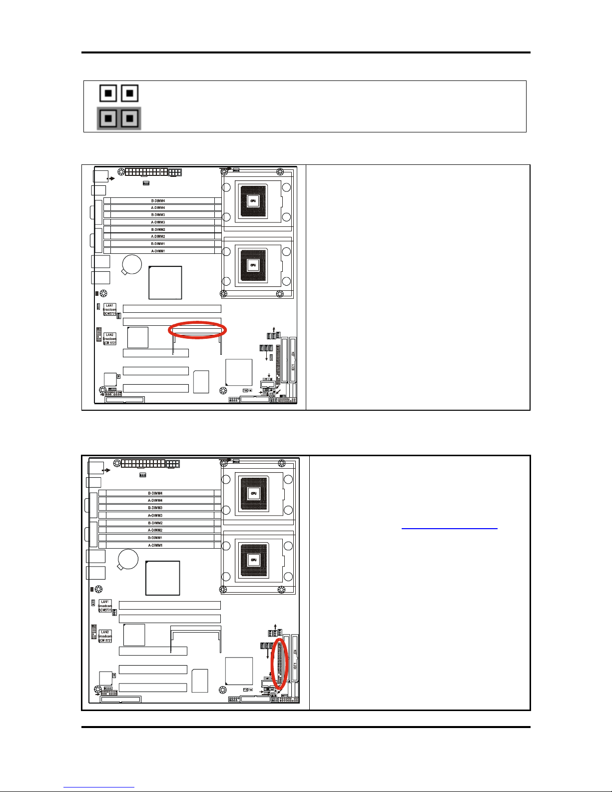
2.5.2 SO-DIMM Socket: J19 (for Tiger i7320R S5350-1U only))
S5350
1
J4
USB1
J3
(COM1)
J2
(VGA)
CPUFAN1
PW1
LAN1
BIOS
Intel
6300ESB
SATA1
SATA2
FDD1 J5
J22
1
SMSC
DME1737
64-bit 66MHz PCI-X PCIX-P1
KB(Botto m)
Mouse(Top)
J1
KB / MS
LAN2
ATI
RAGE XL
LPT1
USB2
SMDC J21
BATT
64-bit 66MHz PCI-X PCIX-P 2 (Optional)
Intel
E7320
IDE2 J23
PW2
SO_DIMM PCIX- P3 J1 9(Optiona l)
1
FAN3
1
FAN7
JP4
1
J36
JP7
1
CPU1
1
FAN2
FAN1
1
CPU2
32-bit 33MHz (5V)PCI PCI-1 (Optional)
32-bit 33MHz (5V)PCI PCI-2 (Optional)
32-bit 33MHz (5V)PCI PCI-3 (Optional)
1
FAN6
1
JP22/27
COM2
JP16
1
JP21
JP24
JP32
LED1
1
JP8
CPUFAN2
FAN5
FAN4
1
JP25
JP30
JP37
11
1
JP39
JP18
JP29
JP13
JP15
1
1
JP28
JP1
1
This socket provides the connection to
SCSI/SATA Daughter Card (compatible with
Tyan M7901/M7902/M8110)
2.5.3 SMDC Connector: J21 (Optional)
S5350
1
J4
USB1
J3
(COM1)
J2
(VGA)
CPUFAN 1
PW1
LAN1
BIOS
Intel
6300ESB
SATA1
SATA2
FDD1 J5
J22
1
SMSC
DME1737
64-bit 66MHz PCI-X PCIX-P1
KB(Botto m)
Mouse(Top)
J1
KB / MS
LAN2
ATI
RAGE XL
LPT1
USB2
SMDC J21
BATT
64-bit 66MHz PCI-X PCIX-P 2 (Optional)
Intel
E7320
IDE2 J23
PW2
SO_DI MM P CIX- P3 J 19(Opt iona l)
1
FAN 3
1
FAN7
JP4
1
J36
JP7
1
CPU1
1
FAN2
FAN1
1
CPU2
32-bit 33MHz (5V)PCI PCI-1 (Optional)
32-bit 33MHz (5V)PCI PCI-2 (Optional)
32-bit 33MHz (5V)PCI PCI-3 (Optional)
1
FAN6
1
JP22/27
COM2
JP16
1
JP21
JP24
JP32
LED1
1
JP8
CPUFAN2
FAN5
FAN 4
1
JP25
JP30
JP37
11
1
JP39
JP18
JP29
JP13
JP15
1
1
JP28
JP1
1
For connection with Tyan Server
Management Daughter Card (SMDC)
More information on Tyan SMDC card please
visit our website at http://www.tyan.com
Tiger i7320 / Tiger i7320R Chapter 2: Board Installation
2-8
http://www.tyan.com
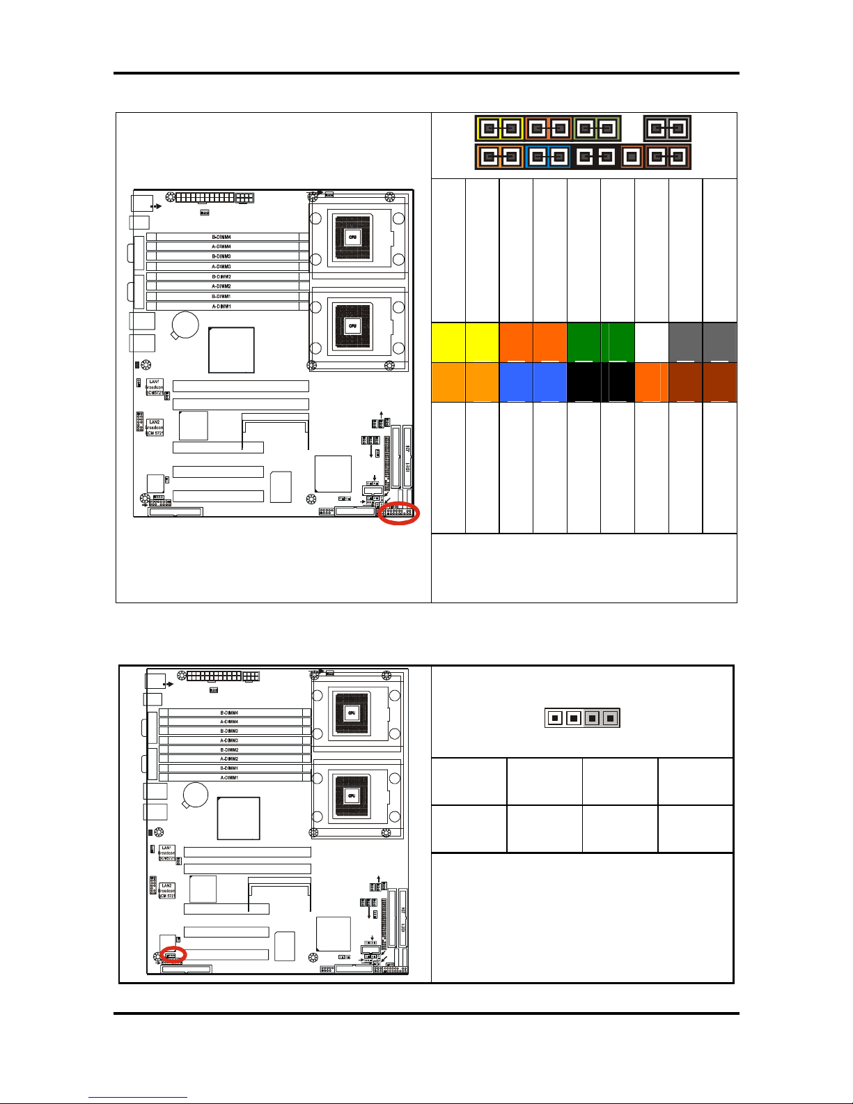
2.5.4 Front Panel Connector: J22
2
1
18
17
PWR_LED+
PWR_LED-
POWER BUTTON
GND
LED+ (reserved)
LED- (reserved)
NC
GND
INTRU#
2
4
6
8
10
12
14
16
18
1
3
5
7
9
11
13
15
17
HD_LED+
HD_LED-
GND
RESET+
+5V
EXT
+5VSB
SMBUS DATA
SMBUS CLOCK
S5350
1
J4
USB1
J3
(COM1 )
J2
(VGA)
CPUFAN1
PW1
LAN1
BIOS
Intel
6300ESB
SATA1
SATA2
FDD1 J5
J22
1
SMSC
DME1737
64-bit 66MHz PCI-X PCIX-P1
KB(Bottom)
Mouse(Top)
J1
KB / MS
LAN2
ATI
RAGE XL
LPT1
USB2
SMDC J21
BATT
64-bit 66MHz PCI-X PCIX-P 2 (Optional)
Intel
E7320
IDE2 J23
PW2
SO_DIMM PCIX-P 3 J19(Opt ional)
1
FAN3
1
FAN7
JP4
1
J36
JP7
1
CPU1
1
FAN2
FAN1
1
CPU2
32-bit 33MHz (5V)PCI PCI-1 (Optional)
32-bit 33MHz (5V)PCI PCI-2 (Optional)
32-bit 33MHz (5V)PCI PCI-3 (Optional)
1
FAN6
1
JP22/27
COM2
JP16
1
JP21
JP24
JP32
LED1
1
JP8
CPUFAN 2
FAN5
FAN4
1
JP25
JP30
JP37
11
1
JP39
JP18
JP29
JP13
JP15
1
1
JP28
JP1
1
Use this header to connect various front panel
indicators and buttons.
2.5.5 External speaker Header: JP4
41
1 2 3 4
+5V NC NC SPKR-
S5350
1
J4
USB1
J3
(COM1)
J2
(VGA)
CPUFAN1
PW1
LAN1
BIOS
Intel
6300ESB
SATA1
SATA2
FDD1 J5
J22
1
SMSC
DME1737
64-bit 66MHz PCI-X PCIX-P1
KB(Bottom)
Mouse(Top)
J1
KB / MS
LAN2
ATI
RAGE XL
LPT1
USB2
SMDC J21
BATT
64-bit 66MHz PCI-X PCIX-P 2 (Optional)
Intel
E7320
IDE2 J23
PW2
SO_DIMM PCIX- P3 J1 9(Optional )
1
FAN3
1
FAN7
JP4
1
J36
JP7
1
CPU1
1
FAN2
FAN1
1
CPU2
32-bit 33MHz (5V)PCI PCI-1 (Optional)
32-bit 33MHz (5V)PCI PCI-2 (Optional)
32-bit 33MHz (5V)PCI PCI-3 (Optional)
1
FAN6
1
JP22/27
COM2
JP16
1
JP21
JP24
JP32
LED1
1
JP8
CPUFAN2
FAN5
FAN4
1
JP25
JP30
JP37
11
1
JP39
JP18
JP29
JP13
JP15
1
1
JP28
JP1
1
Use this pin header to connect external
speakers.
Pin3-4 Closed: Buzzer (Default)
Tiger i7320 / Tiger i7320R Chapter 2: Board Installation
2-9
http://www.tyan.com
2.5.6 Chassis Fan Connectors with Fan Control: FAN 1/2/3/4/5
+12V
GND
Tachometer
S5350
1
J4
USB1
J3
(COM1 )
J2
(VGA)
CPUFAN1
PW1
LAN1
BIOS
Intel
6300ESB
SATA1
SATA2
FDD1 J5
J22
1
SMSC
DME1737
64-bit 66MHz PCI-X PCIX-P1
KB(Bo ttom)
Mouse(Top)
J1
KB / MS
LAN2
ATI
RAGE XL
LPT1
USB2
SMDC J21
BATT
64-bit 66MHz PCI-X PCIX-P 2 (Optional)
Intel
E7320
IDE2 J23
PW2
SO_DIM M PCIX-P3 J1 9(Opti onal)
1
FAN3
1
FAN7
JP4
1
J36
JP7
1
CPU1
1
FAN2
FAN1
1
CPU2
32-bit 33MHz (5V)PCI PCI-1 (Optional)
32-bit 33MHz (5V)PCI PCI-2 (Optional)
32-bit 33MHz (5V)PCI PCI-3 (Optional)
1
FAN6
1
JP22/27
COM2
JP16
1
JP21
JP24
JP32
LED1
1
JP8
CPUFAN2
FAN5
FAN4
1
JP25
JP30
JP37
11
1
JP39
JP18
JP29
JP13
JP15
1
1
JP28
JP1
1
Use these headers to connect the chassis
cooling fans to your motherboard to keep
the system stable and reliable.
These connectors support the tachometer
monitoring and auto fan speed control.
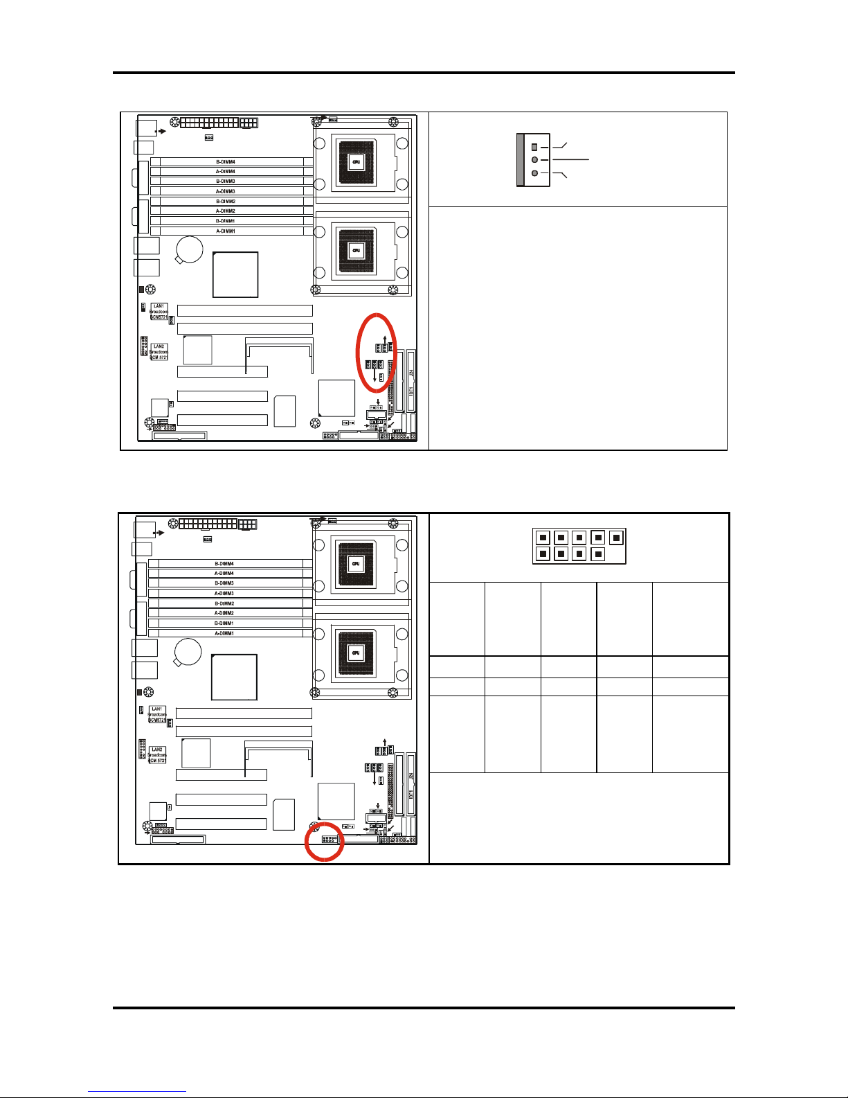
2.5.7 Front Panel USB 2.0 Connector: JP13 (USB2)
1 9
2 10
+5V
Data 2-
Data 2+
GND
GND
2 4 6 8 10
1 3 5 7 9
+5V
Data 1-
Data 1+
GND
NC/Key
S5350
1
J4
USB1
J3
(COM1)
J2
(VGA)
CPUFAN1
PW1
LAN1
BIOS
Intel
6300ESB
SATA1
SATA2
FDD1 J5
J22
1
SMSC
DME1737
64-bit 66MHz PCI-X PCIX-P1
KB(Botto m)
Mouse(Top)
J1
KB / MS
LAN2
ATI
RAGE XL
LPT1
USB2
SMDC J21
BATT
64-bit 66MHz PCI-X PCIX-P 2 (Optional)
Intel
E7320
IDE2 J23
PW2
SO_DIMM PCIX- P3 J1 9(Optiona l)
1
FAN3
1
FAN7
JP4
1
J36
JP7
1
CPU1
1
FAN2
FAN1
1
CPU2
32-bit 33MHz (5V)PCI PCI-1 (Optional)
32-bit 33MHz (5V)PCI PCI-2 (Optional)
32-bit 33MHz (5V)PCI PCI-3 (Optional)
1
FAN6
1
JP22/27
COM2
JP16
1
JP21
JP24
JP32
LED1
1
JP8
CPUFAN2
FAN5
FAN4
1
JP25
JP30
JP37
11
1
JP39
JP18
JP29
JP13
JP15
1
1
JP28
JP1
1
Use these headers to connect to the USB
devices via the enclosed USB cable.
Tiger i7320 / Tiger i7320R Chapter 2: Board Installation
2-10
http://www.tyan.com
2.5.8 CPU FAN1/FAN2 Connectors
+12V
Tachom eterGND
+12V
GND
Tachometer
S5350
1
J4
USB1
J3
(COM1 )
J2
(VGA)
CPUFAN1
PW1
LAN1
BIOS
Intel
6300ESB
SATA1
SATA2
FDD1 J5
J22
1
SMSC
DME1737
64-bit 66MHz PCI-X PCIX-P1
KB(Bo ttom)
Mouse(Top)
J1
KB / MS
LAN2
ATI
RAGE XL
LPT1
USB2
SMDC J21
BATT
64-bit 66MHz PCI-X PCIX-P 2 (Optional)
Intel
E7320
IDE2 J23
PW2
SO_DIM M PCIX-P3 J1 9(Opti onal)
1
FAN3
1
FAN7
JP4
1
J36
JP7
1
CPU1
1
FAN2
FAN1
1
CPU2
32-bit 33MHz (5V)PCI PCI-1 (Optional)
32-bit 33MHz (5V)PCI PCI-2 (Optional)
32-bit 33MHz (5V)PCI PCI-3 (Optional)
1
FAN6
1
JP22/27
COM2
JP16
1
JP21
JP24
JP32
LED1
1
JP8
CPUFAN2
FAN5
FAN4
1
JP25
JP30
JP37
11
1
JP39
JP18
JP29
JP13
JP15
1
1
JP28
JP1
1
Use these headers to connect the CPU
cooling fans to your motherboard to keep
the system stable and reliable.
These connectors support the tachometer
monitoring and auto fan speed control.
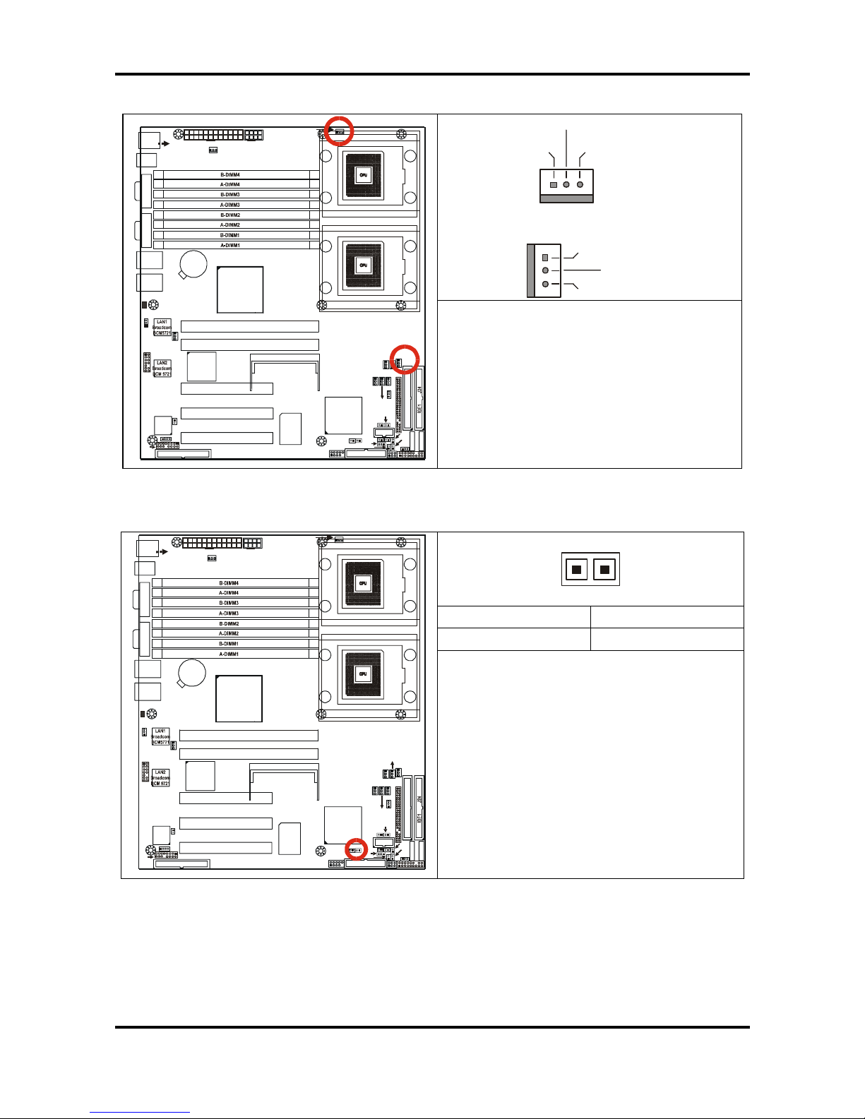
2.5.9 SATA activity LED Header: JP16
1
2 1
LED- LED+
S5350
1
J4
USB1
J3
(COM1)
J2
(VGA)
CPUFAN1
PW1
LAN1
BIOS
Intel
6300ESB
SATA1
SATA2
FDD1 J5
J22
1
SMSC
DME1737
64-bit 66MHz PCI-X PCIX-P1
KB(Bottom)
Mouse(Top)
J1
KB / MS
LAN2
ATI
RAGE XL
LPT1
USB2
SMDC J21
BATT
64-bit 66MHz PCI-X PCIX-P 2 (Optional)
Intel
E7320
IDE2 J23
PW2
SO_DIMM PCIX- P3 J19(Optional )
1
FAN3
1
FAN7
JP4
1
J36
JP7
1
CPU1
1
FAN2
FAN1
1
CPU2
32-bit 33MHz (5V)PCI PCI-1 (Optional)
32-bit 33MHz (5V)PCI PCI-2 (Optional)
32-bit 33MHz (5V)PCI PCI-3 (Optional)
1
FAN6
1
JP22/27
COM2
JP16
1
JP21
JP24
JP32
LED1
1
JP8
CPUFAN2
FAN5
FAN4
1
JP25
JP30
JP37
11
1
JP39
JP18
JP29
JP13
JP15
1
1
JP28
JP1
1
Use this header to connect an activity
indicator LED for an external SATA device.
Tiger i7320 / Tiger i7320R Chapter 2: Board Installation
2-11
http://www.tyan.com
2.5.10 Chassis Fan Connectors: FAN6, FAN7
+12V
GND
NC
S5350
1
J4
USB1
J3
(COM1 )
J2
(VGA)
CPUFAN1
PW1
LAN1
BIOS
Intel
6300ESB
SATA1
SATA2
FDD1 J5
J22
1
SMSC
DME1737
64-bit 66MHz PCI-X PCIX-P1
KB(Bo ttom)
Mouse(Top)
J1
KB / MS
LAN2
ATI
RAGE XL
LPT1
USB2
SMDC J21
BATT
64-bit 66MHz PCI-X PCIX-P 2 (Optional)
Intel
E7320
IDE2 J23
PW2
SO_DIM M PCIX-P3 J1 9(Opti onal)
1
FAN3
1
FAN7
JP4
1
J36
JP7
1
CPU1
1
FAN2
FAN1
1
CPU2
32-bit 33MHz (5V)PCI PCI-1 (Optional)
32-bit 33MHz (5V)PCI PCI-2 (Optional)
32-bit 33MHz (5V)PCI PCI-3 (Optional)
1
FAN6
1
JP22/27
COM2
JP16
1
JP21
JP24
JP32
LED1
1
JP8
CPUFAN2
FAN5
FAN4
1
JP25
JP30
JP37
11
1
JP39
JP18
JP29
JP13
JP15
1
1
JP28
JP1
1
Use this header to connect the chassis
cooling fans to your motherboard to keep
the system stable and reliable.
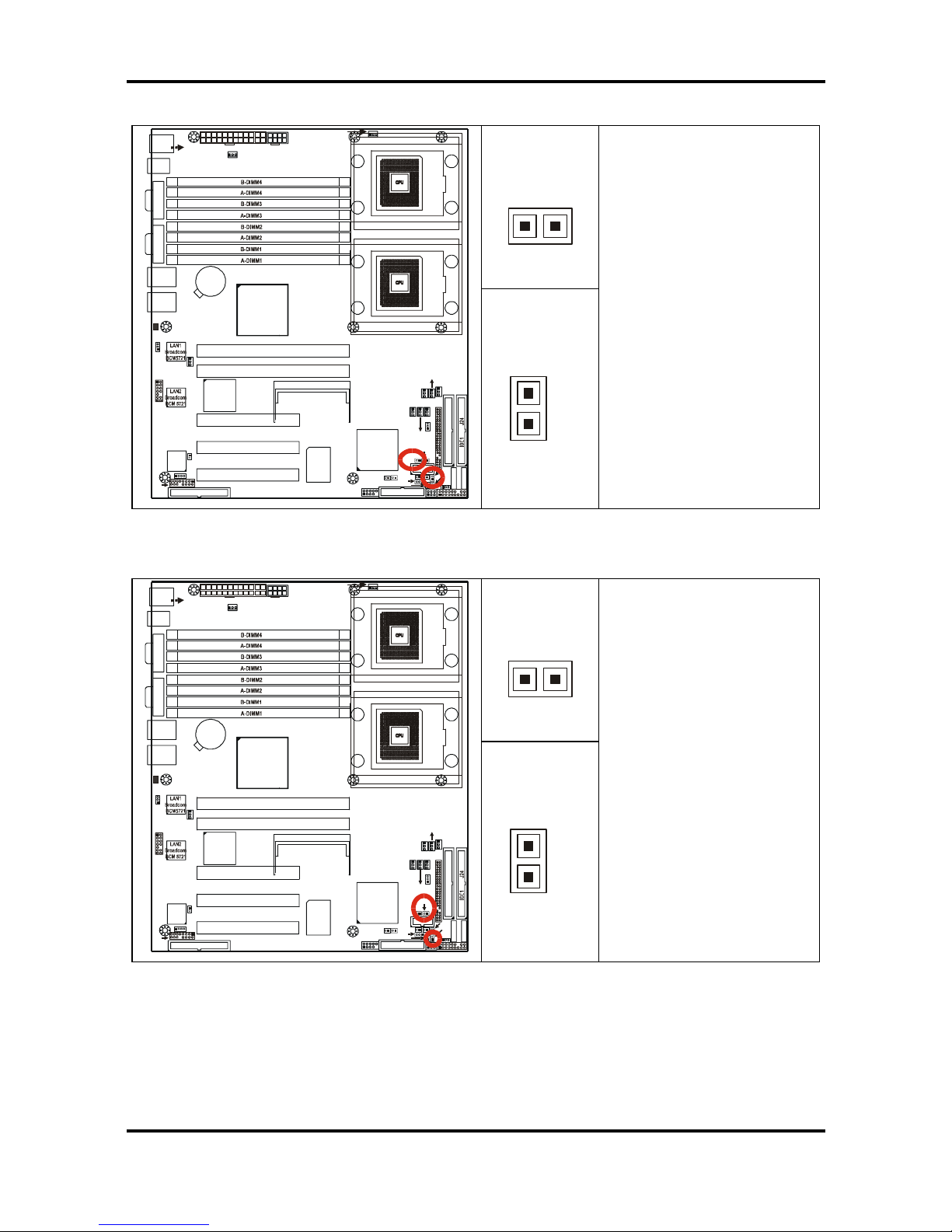
2.5.11 COM2 connector: JP18
1 9
2 10
DSR
RTS
CTS
RI
NC/Key
2 4 6 8 10
1 3 5 7 9
DCD
RXD
TXD
DTR
GND
S5350
1
J4
USB1
J3
(COM1 )
J2
(VGA )
CPUFAN1
PW1
LAN1
BIOS
Intel
6300ESB
SATA1
SATA2
FDD1 J5
J22
1
SMSC
DME1737
64-bit 66MHz PCI-X PCIX-P1
KB(Bottom)
Mouse(Top)
J1
KB / MS
LAN2
ATI
RAGE XL
LPT1
USB2
SMDC J21
BATT
64-bit 66MHz PCI-X PCIX-P 2 (Optional)
Intel
E7320
IDE2 J23
PW2
SO_DIMM PCIX- P3 J19(O ptional )
1
FAN3
1
FAN7
JP4
1
J36
JP7
1
CPU1
1
FAN2
FAN1
1
CPU2
32-bit 33MHz (5V)PCI PCI-1 (Optional)
32-bit 33MHz (5V)PCI PCI-2 (Optional)
32-bit 33MHz (5V)PCI PCI-3 (Optional)
1
FAN6
1
JP22/27
COM2
JP16
1
JP21
JP24
JP32
LED1
1
JP8
CPUFAN2
FAN5
FAN4
1
JP25
JP30
JP37
11
1
JP39
JP18
JP29
JP13
JP15
1
1
JP28
JP1
1
Use this connector to connect the UART
device via the enclosed COM2 cable
Tiger i7320 / Tiger i7320R Chapter 2: Board Installation
2-12
http://www.tyan.com
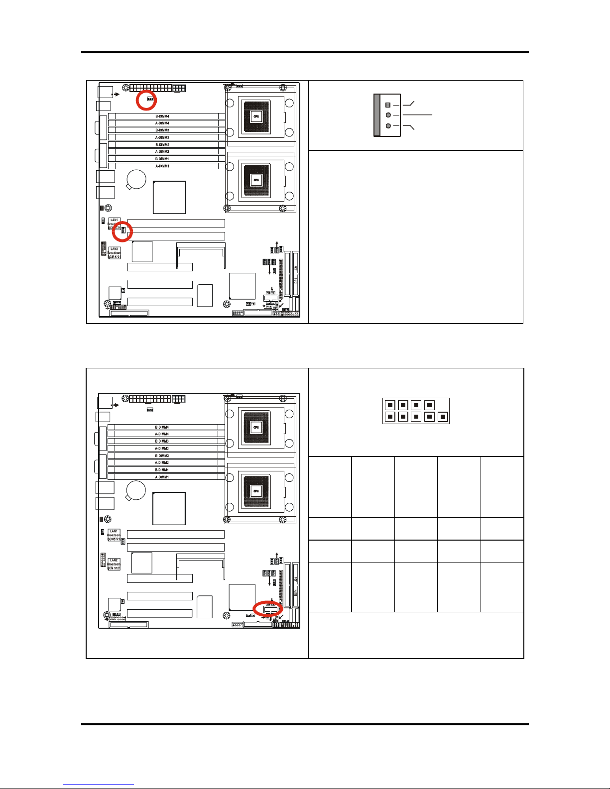
2.5.12 LAN1/LAN2 activity LED Headers: JP21, JP30
JP21
1
S5350
1
J4
USB1
J3
(COM1)
J2
(VGA )
CPUFAN1
PW1
LAN1
BIOS
Intel
6300ESB
SATA1
SATA2
FDD1 J5
J22
1
SMSC
DME1737
64-bit 66MHz PCI-X PCIX-P1
KB(Bottom)
Mouse(Top)
J1
KB / MS
LAN2
ATI
RAGE XL
LPT1
USB2
SMDC J21
BATT
64-bit 66MHz PCI-X PCIX-P 2 (Optional)
Intel
E7320
IDE2 J23
PW2
SO_DIMM PCIX-P 3 J19(Opt ional)
1
FAN3
1
FAN7
JP4
1
J36
JP7
1
CPU1
1
FAN 2
FAN1
1
CPU2
32-bit 33MHz (5V)PCI PCI-1 (Optional)
32-bit 33MHz (5V)PCI PCI-2 (Optional)
32-bit 33MHz (5V)PCI PCI-3 (Optional)
1
FAN6
1
JP22/27
COM2
JP16
1
JP21
JP24
JP32
LED1
1
JP8
CPUFAN2
FAN5
FAN 4
1
JP25
JP30
JP37
11
1
JP39
JP18
JP29
JP13
JP15
1
1
JP28
JP1
1
JP30
1
Pin 1: LED+
Pin 2: LED-
Use these headers to
connect with the front
panel activity LEDs for
LAN1/LAN2.
2.5.13 LAN1/LAN2 speed LED Headers: JP24, JP29
JP24
1
S5350
1
J4
USB1
J3
(COM1)
J2
(VGA )
CPUFAN1
PW1
LAN1
BIOS
Intel
6300ESB
SATA1
SATA2
FDD1 J5
J22
1
SMSC
DME1737
64-bit 66MHz PCI-X PCIX-P1
KB(Bottom)
Mouse(Top)
J1
KB / MS
LAN2
ATI
RAGE XL
LPT1
USB2
SMDC J21
BATT
64-bit 66MHz PCI-X PCIX-P 2 (Optional)
Intel
E7320
IDE2 J23
PW2
SO_DIMM PCIX-P 3 J19(Opt ional)
1
FAN3
1
FAN7
JP4
1
J36
JP7
1
CPU1
1
FAN 2
FAN1
1
CPU2
32-bit 33MHz (5V)PCI PCI-1 (Optional)
32-bit 33MHz (5V)PCI PCI-2 (Optional)
32-bit 33MHz (5V)PCI PCI-3 (Optional)
1
FAN6
1
JP22/27
COM2
JP16
1
JP21
JP24
JP32
LED1
1
JP8
CPUFAN2
FAN5
FAN 4
1
JP25
JP30
JP37
11
1
JP39
JP18
JP29
JP13
JP15
1
1
JP28
JP1
1
JP29
1
Pin 1: Orange+
Pin 2: Green+
Use these headers to
connect with the front
panel dual color LEDs to
indicate the speed of
LAN1 and LAN2.
Off=10
Green=100
Orange=Gigabit
Reference Section 2.10.1
for the correct LAN LED
Color scheme
JP24 is for LAN1, JP29 is
for LAN2.
Tiger i7320 / Tiger i7320R Chapter 2: Board Installation
2-13
http://www.tyan.com
2.5.14 Clear CMOS Jumper: JP25
3
1
Pin 1-2:
Normal (Default)
3
1
Pin 2-3:
Clear BIOS
S5350
1
J4
USB1
J3
(COM 1)
J2
(VGA)
CPUFAN1
PW1
LAN1
BIOS
Intel
6300ESB
SATA1
SATA2
FDD1 J5
J22
1
SMSC
DME1737
64-bit 66MHz PCI-X PCIX-P1
KB(Bottom)
Mouse( Top)
J1
KB / MS
LAN2
ATI
RAGE XL
LPT1
USB2
SMDC J21
BATT
64-bit 66MHz PCI-X PCIX-P 2 (Optional)
Inte l
E7320
IDE2 J23
PW2
SO_DIMM PCIX-P3 J19(Opti onal)
1
FAN 3
1
FAN7
JP4
1
J36
JP7
1
CPU1
1
FAN2
FAN1
1
CPU2
32-bit 33MHz (5V)PCI PCI-1 (Optional)
32-bit 33MHz (5V)PCI PCI-2 (Optional)
32-bit 33MHz (5V)PCI PCI-3 (Optional)
1
FAN6
1
JP22/27
COM2
JP16
1
JP21
JP24
JP32
LED1
1
JP8
CPUFAN2
FAN 5
FAN4
1
JP25
JP30
JP37
11
1
JP39
JP18
JP29
JP13
JP15
1
1
JP28
JP1
1
Use this jumper when you forgot your
system/setup password or need to clear
system BIOS setting.
How to clear the CMOS data
- Power off system and disconnect
power supply from AC source
- Use jumper cap to close Pin_2 and 3 for
several seconds to Clear CMOS
- Replace jumper cap to close Pin_1 and
2 (default setting)
- Reconnect power supply to AC source
Power on system
2.5.15 3-pin Power LED Connector: JP32
13
1 2 3
LED+ NC LED-
S5350
1
J4
USB1
J3
(COM1 )
J2
(VGA)
CPUFAN1
PW1
LAN1
BIOS
Intel
6300ESB
SATA1
SATA2
FDD1 J5
J22
1
SMSC
DME1737
64-bit 66MHz PCI-X PCIX-P1
KB(Bo ttom)
Mouse(Top)
J1
KB / MS
LAN2
ATI
RAGE XL
LPT1
USB2
SMDC J21
BATT
64-bit 66MHz PCI-X PCIX-P 2 (Optional)
Intel
E7320
IDE2 J23
PW2
SO_DIM M P CIX- P3 J 19(O ptiona l)
1
FAN3
1
FAN7
JP4
1
J36
JP7
1
CPU1
1
FAN2
FAN1
1
CPU2
32-bit 33MHz (5V)PCI PCI-1 (Optional)
32-bit 33MHz (5V)PCI PCI-2 (Optional)
32-bit 33MHz (5V)PCI PCI-3 (Optional)
1
FAN6
1
JP22/27
COM2
JP16
1
JP21
JP24
JP32
LED1
1
JP8
CPUFAN2
FAN5
FAN4
1
JP25
JP30
JP37
11
1
JP39
JP18
JP29
JP13
JP15
1
1
JP28
JP1
1
Use this header to connect the 3-pin
power LED cable
Tiger i7320 / Tiger i7320R Chapter 2: Board Installation
2-14
http://www.tyan.com
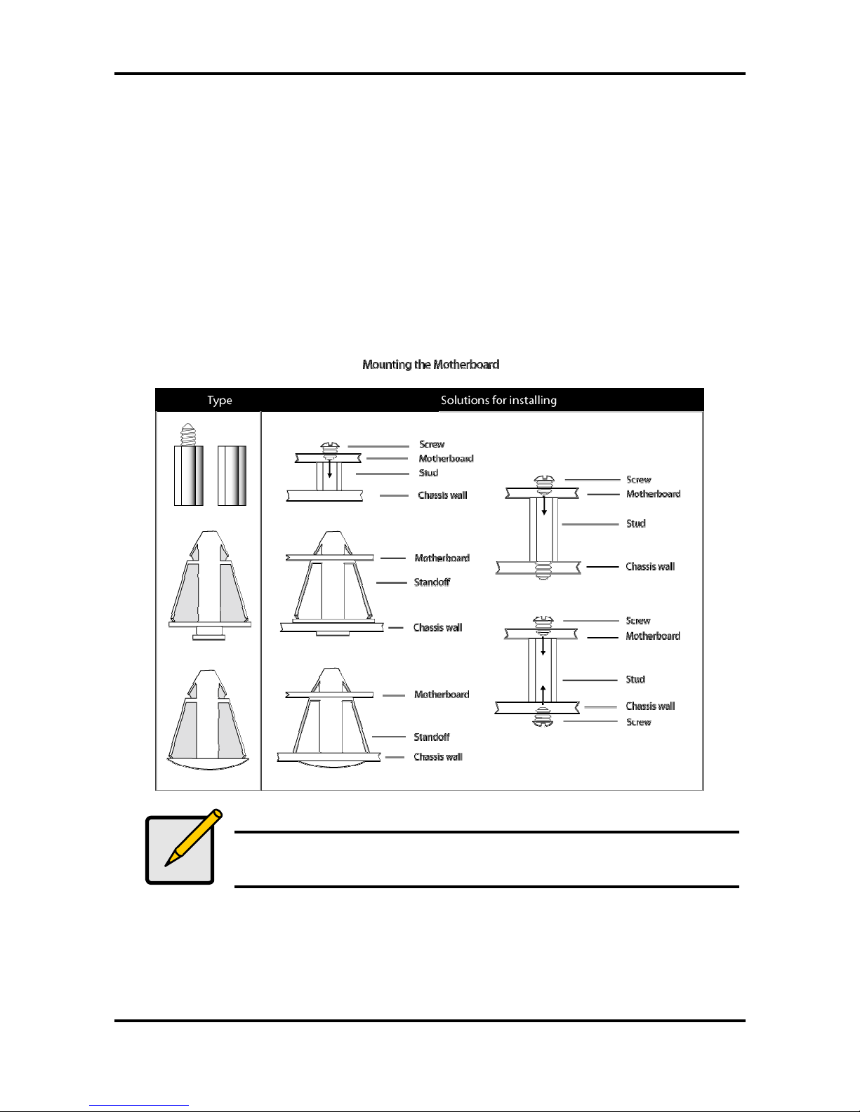
2.6 Mounting the Motherboard
Before installing your motherboard, ensure that your chassis is fully compatible. The Tiger
i7320 S5350 / Tiger i7320R S5350-1U motherboard conforms fully to the CEB specification.
Your chassis should include preinstalled mounting posts that match exactly with the mounting
holes in the motherboard. Lay the motherboard on top of the mounting holes to ensure that all
the necessary mounting posts exist in your chassis and that they match the mounting holes on
the motherboard.
Some chassis’ include plastic studs instead of metal. Although the plastic studs are usable,
TYAN recommends using metal studs with screws that will fasten the motherboard more
securely in place.
The diagram below is an example of typical motherboard fixing studs.
Note
Use metal studs if possible, as they hold the motherboard in place more
securely than plastic standoffs.

Tiger i7320 / Tiger i7320R Chapter 2: Board Installation
2-15
http://www.tyan.com
2.6.1 Installing Memory
Before installing memory, ensure that the memory you have is compatible with the
motherboard and processor. DDR 266/333 modules are required. Check the TYAN Web site
at:
www.tyan.com
for details of the type of memory recommended for your motherboard.
The following diagram shows common types of memory modules.
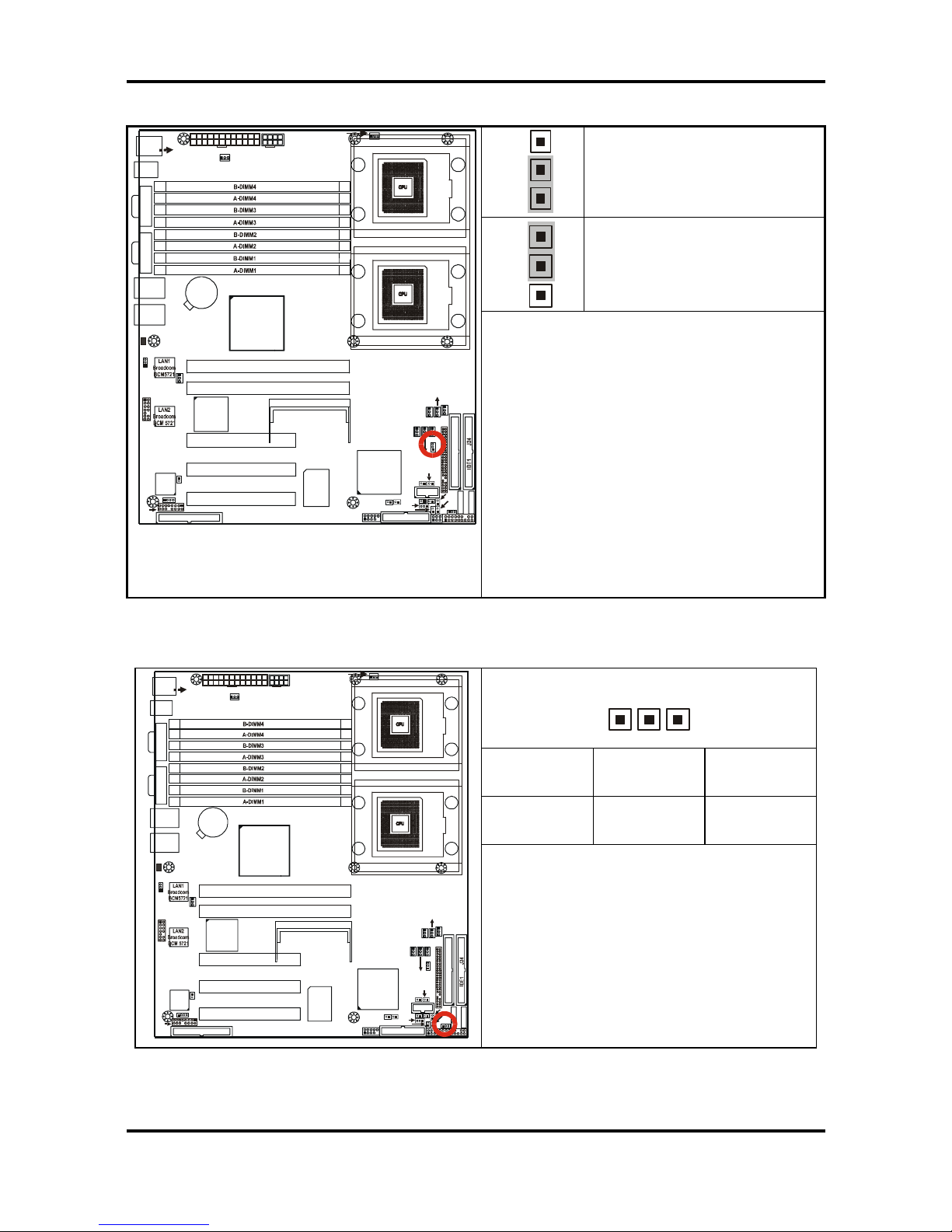
Key points to note before installing memory into Tiger i7320 / i7320R:
•
Always install memory beginning with DIMM4
• 128MB, 256MB, 512MB, 1GB, 2GB and 4GB* Registered ECC PC2700/PC2100
DDR SDRAM memory modules are supported
• All installed memory will be automatically detected.
• The Tiger i7320 S5350 / Tiger i7320R S5350-1U supports up to 32GB* of memory.
• Registered ECC Memory is supported.
•
Either single or dual-rank modules are supported.
• Memory modules of the same type and density are required for dual-channel DDR
operation. Mismatched memory may cause system instability.
* Not validated at the time of print; subject to change.
Refer to the following table for supported DDR-333/266 populations
(Note: S indicates a single rank DIMM, D indicates a dual rank DIMM)
DIMM Slot Population
B-DIMM4
S D S S DSS S D S S S S D
A-DIMM4
S D S S DSS S D S S S S D
B-DIMM3
SDDSS D D S S S D D
A-DIMM3
SDDSS D D S S S D D
B-DIMM2
SD D D S S D D D
A-DIMM2
SD D D S S D D D
B-DIMM1
S D D D D
A-DIMM1
S D D D D
Note
Intel E7320 chipset specification lists a limitation of 8 banks of DDR333
memory. However, by design the Tiger i7320/i7320R supports up to 16 banks
of DDR333 memory. Please note that this a feature of Tyan’s breakthrough
engineering design, and similar memory support may not be present on
competitor products that use the Intel E7320 chipset
 Loading...