

TYAN S5221 User Manual

S5221
Version 1.0
Copyright
Copyright © MiTAC Computer Corporation, 2009. All rights reserved. No part of
this manual may be reproduced or translated without prior written consent from
MiTAC Computer Corporation.
Trademark
All registered and unregistered trademarks and company names contained in
this manual are property of their respective owners including, but not limited to
the following.
TYAN® is a trademark of MiTAC Computer Corporation
Intel
®
is a trademark of Intel® Corporation.
Phoenix BIOS
®
is trademark of Phoenix Technologies LTD.
Microsoft
®
, Windows® are trademarks of Microsoft Corporation.
Winbond
®
is a trademark of Winbond Electronics Corporation.
Notice
Information contained in this document is furnished by MiTAC Computer
Corporation and has been reviewed for accuracy and reliability prior to printing.
MiTAC assumes no liability whatsoever, and disclaims any express or implied
warranty, relating to sale and/or use of TYAN
®
products including liability or
warranties relating to fitness for a particular purpose or merchantability. MiTAC
retains the right to make changes to product descriptions and/or specifications
at any time, without notice. In no event will MiTAC be held liable for any direct
or indirect, incidental or consequential damage, loss of use, loss of data or other
malady resulting from errors or inaccuracies of information contained in this
document.

http://www.TYAN®.com
2

http://www.TYAN®.com
3
Contents
Before you begin…......................................................................... 4
Chapter 1: Instruction ....................................................................5
1.1 - Congratulations .......................................................................................5
1.2 - Hardware Specifications.......................................................................... 5
1.3 - Software Specifications ...........................................................................7
Chapter 2: Board Installation......................................................... 9
2.1 - Board Image..........................................................................................10
2.2 - Block Diagram ....................................................................................... 11
2.3 - Board Parts, Jumpers and Connectors .................................................12
2.4 - Installing the Processor .........................................................................16
2.5 - Heat sink Installation .............................................................................17
2.6 - Thermal Interface Material..................................................................... 18
2.7 - Finishing Installing the Heat sink ........................................................... 19
2.8 - Tips on Installing Motherboard in Chassis............................................. 20
2.9 - Installing the Memory ............................................................................22
2.10 - Attaching Drive Cables ........................................................................ 24
2.11 - Installing Add-In Cards ........................................................................25
2.12 - Connecting External Devices ..............................................................26
2.13 - Installing the Power Supply ................................................................. 27
2.14 - Finishing Up ........................................................................................28
Chapter 3: BIOS Setup ................................................................. 29
3.1 - About the BIOS .....................................................................................29
3.2 - BIOS Main Menu ................................................................................... 31
3.3 - BIOS Advanced Menu........................................................................... 38
3.4 - Security Menu........................................................................................45
3.5 - Power Menu .......................................................................................... 46
3.6 - Boot Menu ............................................................................................. 47
3.7 - Exit Menu ..............................................................................................48
Chapter 4: Diagnostics ................................................................ 49
4.1 - Beep Codes........................................................................................... 49
4.2 - Flash Utility............................................................................................ 49
4.3 - BIOS Post Code .................................................................................... 50
Appendix: How to Make a Driver Diskette.................................. 53
Glossary ........................................................................................ 55
Technical Support ........................................................................ 61
http://www.TYAN®.com
4
Before you begin…
Check the box contents!
The retail motherboard package should contain the following:
1x S5221 Motherboard
4 x Serial ATA Cable
1 x USB2.0 cable
1 x S5221 User’s manual
1 x S5221 Quick reference guide
1 x TYAN® Driver CD
1 x I/O shield

http://www.TYAN®.com
5
Chapter 1: Instruction
1.1 - Congratulations
You have purchased one of the most powerful TYAN® S5221 motherboard.
Based on Intel
®
chipset, S5221 is designed to support a serial of Intel® CPUs
and two 240-pin DDR2 sockets up to 8GB un-buffered, non-ECC DDR2
667/800 MHz memory, providing a rich feature set and incredible
performance. Leveraging advanced technology from Intel
®
, S5221 is capable
of offering scalable 32 and 64-bit computing, high-bandwidth memory design,
and lightning-fast PCI, PCI-E bus implementation.
S5221 not only empowers you in today’s demanding IT environment but also
offers a smooth path for future application usage. All of this provides S5221
the power and flexibility to meet the needs of nowadays application.
Remember to visit TYAN®’s Website at http://www.tyan.com. There you can
find information on all of TYAN®’s products with FAQs, online manuals and
BIOS upgrades.
1.2 - Hardware Specifications
Supported CPU
Series
• Intel® Core™2 Extreme QX9000/QX6000
series processor
• Intel® Core™2 Quad Q9000/Q6000 series
• Intel® Core™2 Duo E8000/E7000/E6000/
E4000 series
• Intel® Pentium® dual-core E2000 series
• Intel® Celeron® dual-core E1000 series
• Intel® Celeron® 400 series processor
Socket Type / Q'ty LGA 775 / (1)
Max CPU wattage 130W
Processor
System Bus (MHz) Supports 800/1066/1333 MT/s
GMCH / ICH Intel Q35 / ICH9
Chipset
Super I/O Winbond W83627 DHG-P
Supported DIMM Qty (2) DIMM sockets
DIMM Type / Speed DDR2 667/800 ,non-ECC,UDIMM
Capacity Up to 8GB
Memory channel Dual channels (Dual-channel per CPU)
Memory
Memory voltage 1.8V
http://www.TYAN®.com
6
PCI-E
(1) PCI-E x16 slot (x16 link from Q35 MCH) /
(1) PCI 32-bit/33 MHz slot (from ICH9)
Expansion Slots
Recommended Tyan
Riser Card
M2083-RS, PCI-E x16 1U riser card (left)
M2061→PCI-E x8 to PCI-X
Port Q'ty (2)
LAN
Controller Intel 82574L
Connector (4)
Controller ICH9
Speed 1.5 Gb/s
Storage SATA
RAID N/A
Connector type D-Sub 15pin
Resolution 2048x1536 @ 75 Hz refresh
Graphic
Chipset Embedded graphics controller from Q35
USB
(7) USB2.0 ports (2 at rear, 4 via cable, 1
vertical)
COM (1) port (1 at rear )
VGA (1) D-Sub 15pin VGA port
RJ-45 (2) GbE ports; (1) RJ45 for M3295-2 only
Power
EPS12V Power Supply (24-pin, 8-pin power
connectors), under 350W
Input /Output
SATA (4) SATA connectors
Chipset Winbond W83627DHG-P
Voltage
Monitors voltage for CPU, memory, chipset &
power supply
Fan Total (4) 4-pin headers
Temperature
Monitors temperature for CPU & system
environment
LED
Fan fail LED indicator / Over temperature
warning indicator
System
Monitoring
Others Chassis intrusion detection / Watch Dog timer
Optional Module Tyan Server Management Card M3295-2
Server
Management
M3295-2 Feature
IPMI 2.0 Remote System Mgmt card
• Renesas H8S2167 BMC controller
• BT, KCS, Logging support
• IPMI-over-LAN
• Remote power on/off and reset
http://www.TYAN®.com
7
Brand / ROM size Phoenix/32M
BIOS
Feature
• Supports ACPI 2.0
• Supports boot from USB device
• Power-on mode control for AC power loss
recovery
Form Factor Flex-ATX
Form Factor
Board Dimension
9.0 x 7.5" (229 x 191 mm)
Operation
System
OS supported list Please refer to our OS supported list.
FCC (Doc) Class B
CE (Doc) ●
C-Tick ●
Regulation
VCCI ●
Operating Temp 10° C ~ 35° C (50° F~ 95° F)
Non-operating Temp - 40° C ~ 70° C (-40° F ~ 158° F)
Operating
Environment
In/Non-operating
Humidity
90%, non-condensing at 35° C
RoHS
RoHS 6/6 Complaint
●
Motherboard
(1) TYAN motherboard
Manual (1) User's manual / (1) Quick Ref. Guide
Installation CD (1) Tyan Installation CD
I/O Shield (1) I/O Shield
Accessory list
Cable (4) SATA cables; (1) USB2.0 cable
Optional
accessories
for future
upgrade
Server Management
Card
M3295-2
1.3 - Software Specifications
For OS (operation system) support, please check with TYAN® support for latest
information.

http://www.TYAN®.com
8
http://www.TYAN®.com
9
Chapter 2: Board Installation
You are now ready to install your motherboard.
How to install our products right… the first time
The first thing you should do is reading this user’s manual. It contains important
information that will make configuration and setup much easier. Here are some
precautions you should take when installing your motherboard:
(1) Ground yourself properly before removing your motherboard from the
antistatic bag. Unplug the power from your computer power supply and
then touch a safely grounded object to release static charge (i.e. power
supply case). For the safest conditions, TYAN
®
recommends wearing
a static safety wrist strap.
(2) Hold the motherboard by its edges and do not touch the bottom of the
board, or flex the board in any way.
(3) Avoid touching the motherboard components, IC chips, connectors,
memory modules, and leads.
(4) Place the motherboard on a grounded antistatic surface or on the
antistatic bag that the board was shipped in.
(5) Inspect the board for damage.
The following pages include details on how to install your motherboard into your
chassis, as well as installing the processor, memory, disk drives and cables.
Note:
DO NOT APPLY POWER TO THE BOARD IF IT HAS
BEEN DAMAGED.
http://www.TYAN®.com
10
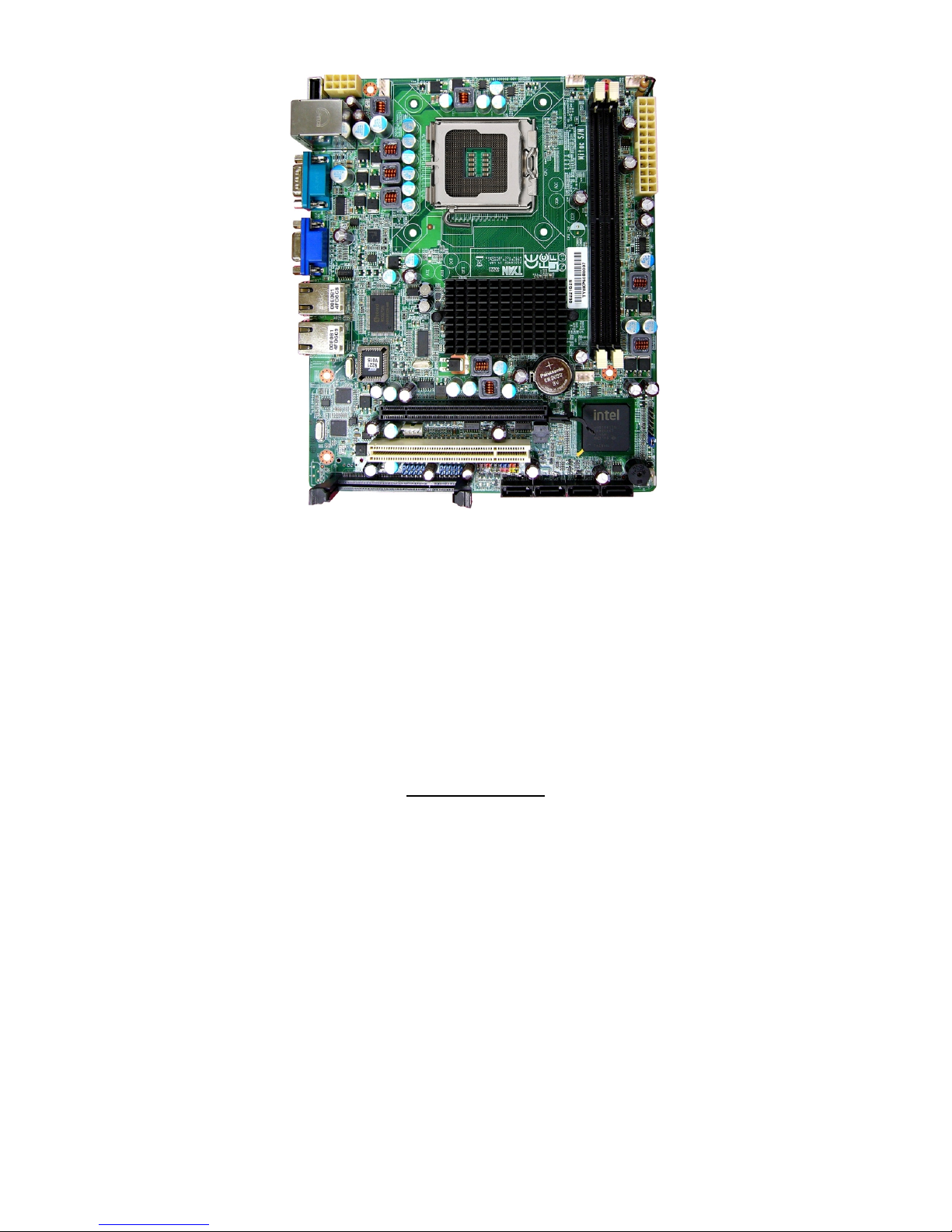
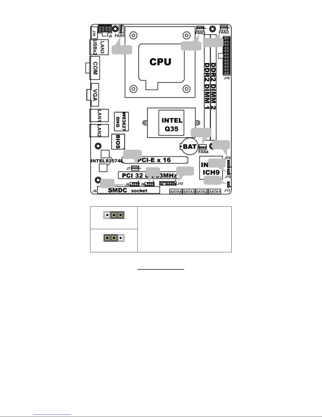
2.1 - Board Image
This picture is representative of the latest board revision available at
the time of publishing. The board you receive may not look exactly like
the above picture.
http://www.TYAN®.com
11
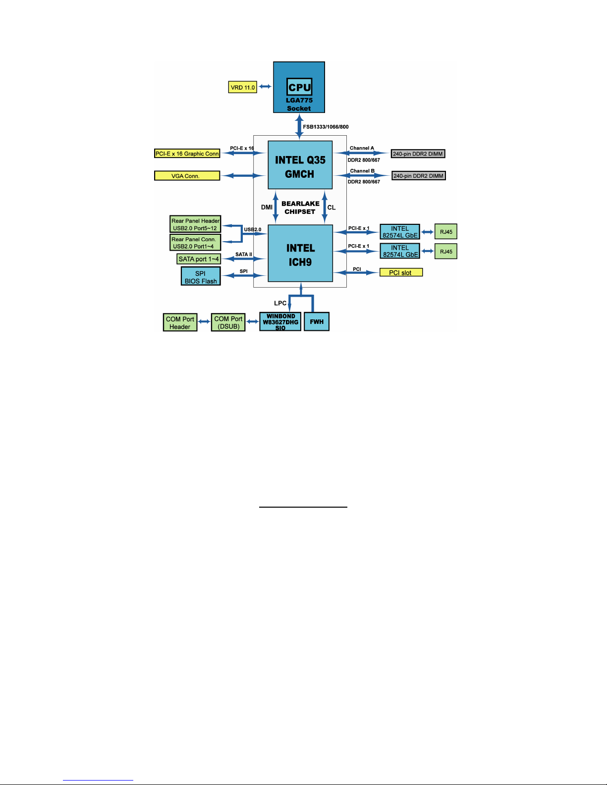
2.2 - Block Diagram
S5221 Block Diagram
http://www.TYAN®.com
12
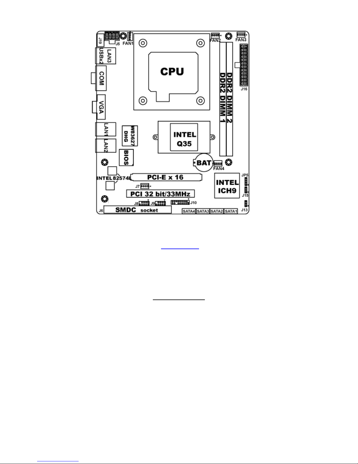
2.3 - Board Parts, Jumpers and Connectors
This diagram is representative of the latest board revision available at the
time of publishing. The board you receive may not look exactly like the above
diagram. But for the DIMM number please refer to the above placement
for memory installation. For the latest board revision, please visit:
www.TYAN.com
http://www.TYAN®.com
13
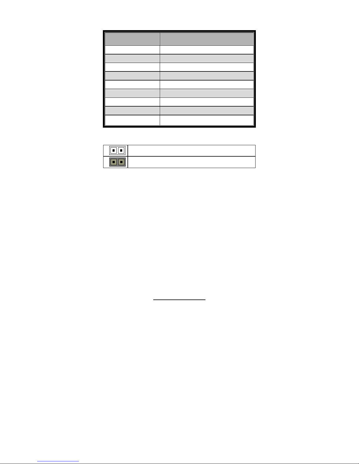
Jumpers & Connectors
Jumper/Connector Function
FAN1/2/3/4 Fan connector
J6 SMDC Socket (option)
J7 FDD Power Connector
J8/9 USB Connector
J10 TYFP1 Connector
J13 Clear CMOS Jumper
J15 WDT Jumper
J19 USB2.0 Port
JP5 Speaker Header
Jumper Legend
OPEN - Jumper OFF
Without jumper cover
CLOSED - Jumper ON
With jumper cover
http://www.TYAN®.com
14
Jumper Placement
J13: Clear CMOS Jumper
Pin_3 Pin_1
Normal (Default)
Pin_3 Pin_1
Clear CMOS
You can reset CMOS by using this jumper if you
have forgotten your system/setup password or
need to clear BIOS setting.
1. Power off system and disconnect both power
connectors from the motherboard.
2. Put jumper cap back to Pin_1 and Pin_2
(default setting).
3. Use jumper cap to close Pin_2 and Pin_3 for
seconds to Clear CMOS.
4. Reconnect power & power on system.
FAN2
FAN1
FAN3
FAN4
J7
J8
J9
J10
JP5
J13
J15
http://www.TYAN®.com
15
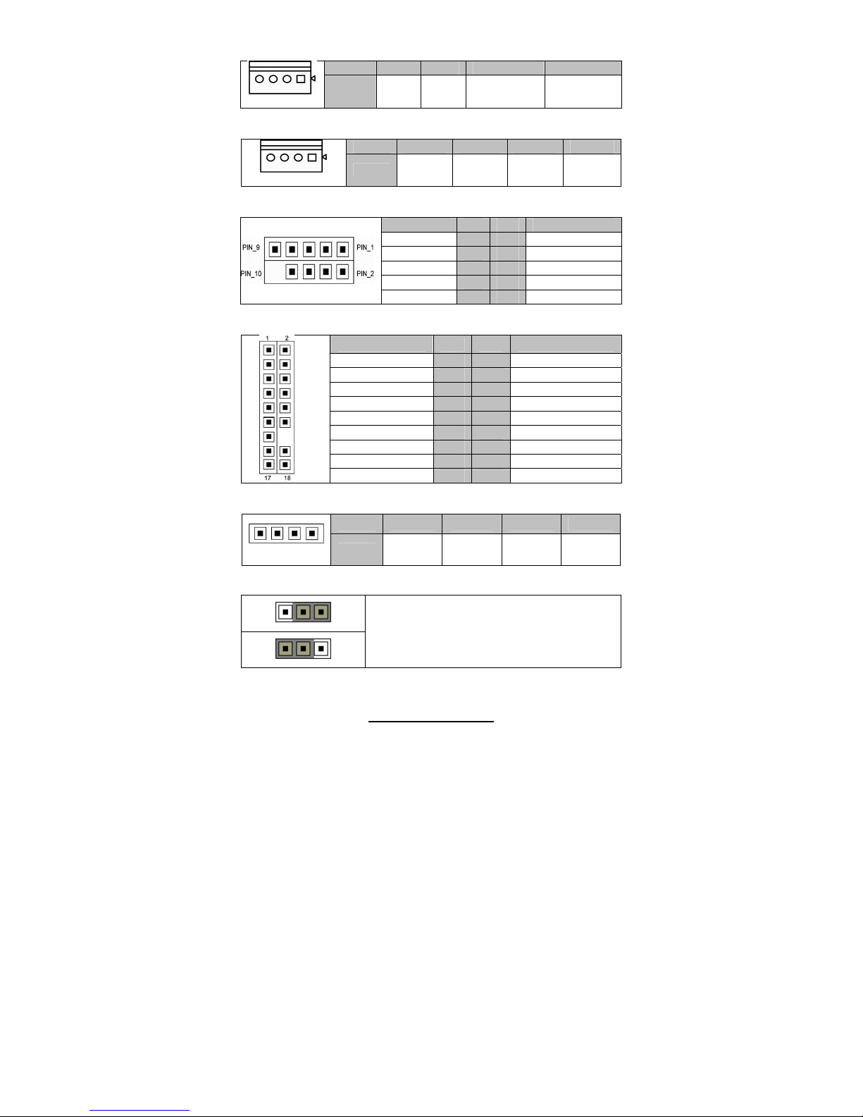
FAN1/2/3/4: 4-Pin FAN Connector
Pin 1 2 3 4
Pin_1
Signal GND +12V FAN_TACH FAN_PWM
J7: FDD Power Connector
Pin 1 2 3 4
Pin_1
Signal
+12V GND GND V5
J8/J9: USB Connector
Signal Pin Pin Signal
PWR
1 2
PWR
USB_A-
3 4
USB_B-
USB_A+
5 6
USB_B+
GND
7 8
GND
GND
9 10
KEY PIN
J10: TYFP1 Connector
Signal Pin Pin Signal
HD LED+
1 2
Power LED+
HD LED-
3 4
Power LED-
GND
5 6
Power S/W+
Reset SW+
7 8
GND
GND
9 10
WLED+
NMI
11 12
WLED-
5Vsb
13 14
KEY PIN
SM Bus Data
15 16
GND
SM Bus Clock
17 18
INTRU#
JP5: Speaker Header
Pin 1 2 3 4
Pin_1
Signal
5V NC NC SPKR
J15: WDT Jumper
Pin_3 Pin_1
Pin_3 Pin_1
Pin1-2 closed: RESET
Pin 2-3 closed: NMI
http://www.TYAN®.com
16
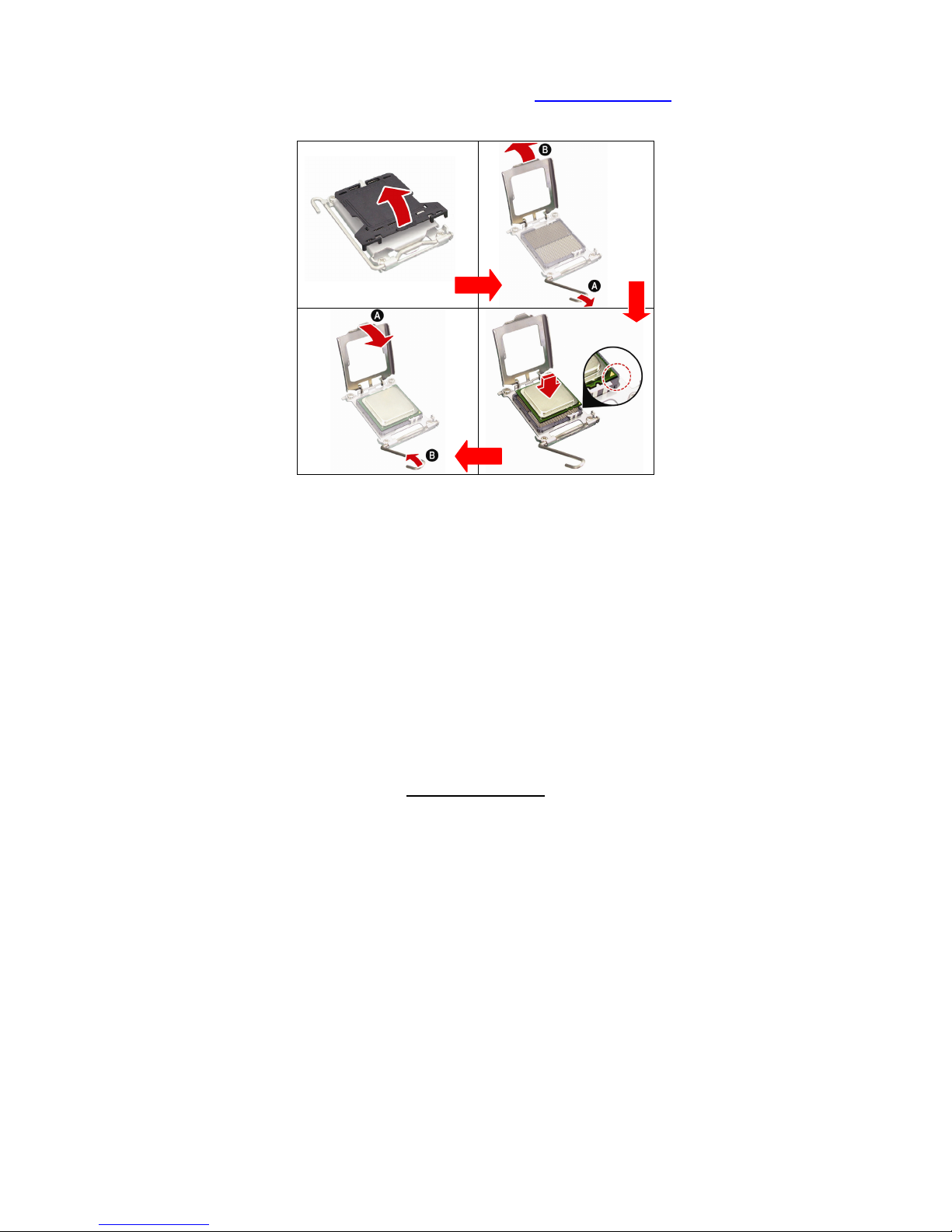
2.4 - Installing the Processor
Your brand S5221 supports Intel® serial CPUs as listed in Chapter 1.1.
Check our website for latest processor support. http://www.TYAN.com
TYAN
®
is not liable for damage as a result of operating an
unsupported configuration.
The diagram is provided as a visual guide to help you to install the socket
processor and may not be an exact representation of the processor you
have.
Step 1: Take off the CPU protection cap.
Step 2: Pull the CPU lever up to unlock the CPU socket (A). Then open the
socket in the direction as shown (B).
Step 3: Place the CPU on the CPU socket, ensuring that pin 1 is located in
the right direction.
Step 4: Close the CPU socket cover (A) and press the CPU socket lever
down to secure the CPU (B).
http://www.TYAN®.com
17
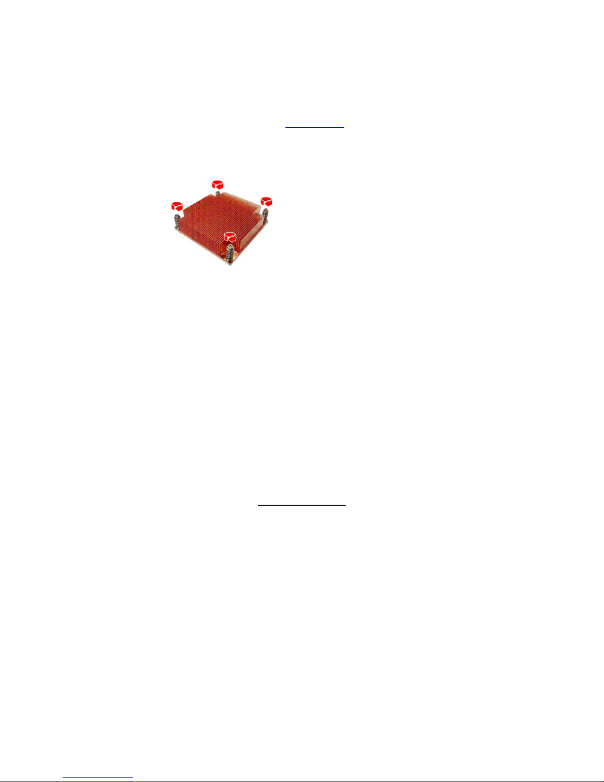
2.5 - Heat sink Installation
After installing the processor, you should proceed to install the heat sink. The
CPU heat sink will ensure that the processor do not overheat and continue to
operate at maximum performance for as long as you own them. The
overheated processor is dangerous to the motherboard.
For the safest method of installation and information on choosing the
appropriate heat sink, using heat sinks validated by Intel®.
Please refer to Intel’ ®s website at www.Intel.com
The following diagram illustrates how to install heat sink onto the CPU of
S5221.
Place the heat sink on top of the CPU
and secure it to the motherboard
using four screws clockwise.
http://www.TYAN®.com
18
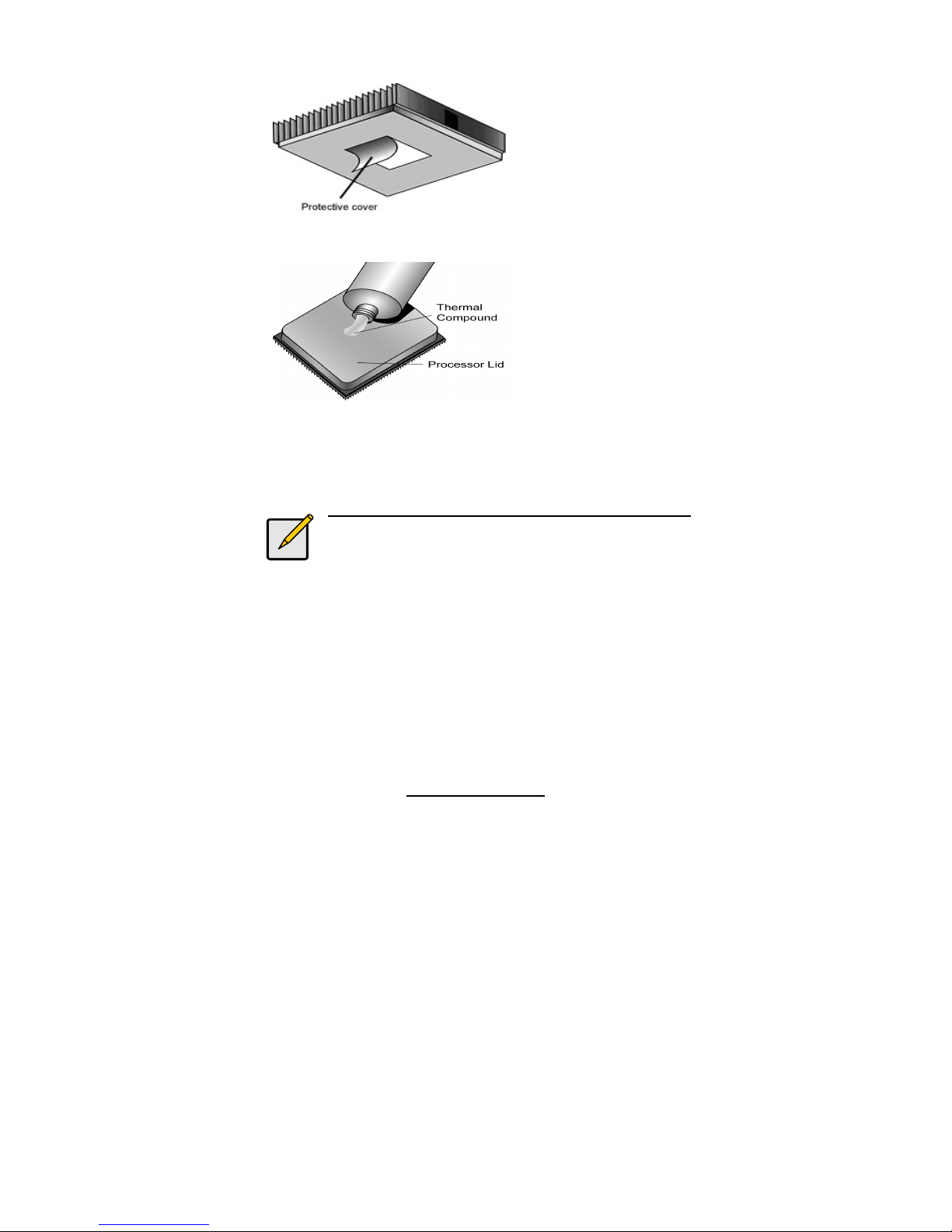
2.6 - Thermal Interface Material
There are two types of
thermal interface materials
designed for use with the
processors.
The most common material
comes as a small pad
attached to the heat sink at
the time of purchase. There
should be a protective cover
over the material. Take care
not to touch this material.
Simply remove the protective
cover and place the heat
sink on the processor.
The second type of interface
material is usually packaged
separately. It is commonly
referred to as ‘thermal
compound’. Simply apply a
thin layer on to the CPU lid
(applying too much will
actually reduce the cooling).
Note:
Always check with the manufacturer of the heat sink &
processor to ensure the Thermal Interface material is
compatible with the processor & meets the manufactu-
-rer’s warranty requirements.

http://www.TYAN®.com
19
2.7 - Finishing Installing the Heat sink
After you have finished installing the heat sink onto the processor and
socket, attach the end wire of the fan (which should already be attached
to the heat sink) to the motherboard. The following diagram illustrates
how to connect fans onto the motherboard.
Once you have finished installing all the fans you can connect your drives
(hard drives, CD-ROM drives, etc.) to your motherboard.
 Loading...