

TYAN Toledo i3010W S5197, S5197 User Manual

1
http://www.tyan.com
Toledo i3010W
///
S5197
Version 1.00
Copyright
Copyright © TYAN Computer Corporation, 2006. All rights reserved. No part of this
manual may be reproduced or translated without prior written consent from TYAN
Computer Corp.
Trademark
All registered and unregistered trademarks and company names contained in this
manual are property of their respective owners including, but not limited to the
following.
TYAN, Toledo i3010W are trademarks of TYAN Computer Corporation.
Intel, Prescott, and combinations thereof are trademarks of Intel Corporation.
Phoenix, Phoenix-Award BIOS are trademarks of Phoenix Technologies.
Microsoft, Windows are trademarks of Microsoft Corporation.
SuSE, is a trademark of Novell.
IBM, PC, AT, and PS/2 are trademarks of IBM Corporation.
Notice
Information contained in this document is furnished by TYAN Computer Corporation
and has been reviewed for accuracy and reliability prior to printing. TYAN assumes
no liability whatsoever, and disclaims any express or implied warranty, relating to
sale and/or use of TYAN products including liability or warranties relating to fitness
for a particular purpose or merchantability. TYAN retains the right to make changes
to product descriptions and/or specifications at any time, without notice. In no event
will TYAN be held liable for any direct or indirect, incidental or consequential
damage, loss of use, loss of data or other malady resulting from errors or
inaccuracies of information contained in this document.

2
http://www.tyan.com
Table of Contents
Check the box contents! 3
Chapter 1: Introduction
1.1 Congratulations 5
1.2 Hardware Specifications 5
1.3 Software Specifications 7
Chapter 2: Board Installation
2.1 Board Image 9
2.2 Block Diagram 10
2.3 Board Parts, Jumpers and Connectors 11
2.4 Jumper Settings 12
2.5 Tips on Installing Motherboard in Chassis 21
2.6 Installing the Memory 23
2.7 Installing the Processor & Cooling Fan 25
2.8 Attaching Drive Cables 28
2.9 Installing Add-in Cards 30
2.10 Connecting External Devices 31
2.11 Installing the Power Supply 32
2.12 Finishing Up 33
Chapter 3: BIOS Setup
3.1 About the BIOS 34
3.2 BIOS Main Setup 36
3.3 Main Menu 37
3.4 Advanced Menu 43
3.5 Security Menu 55
3.6 Power Menu 56
3.7 Boot Menu 57
3.8 Exit Menu 58
Chapter 4: Diagnostics
4.1 Beep Codes 59
4.2 Flash Utility 59
4.3 Phoenix BIOS Post Code 60
Appendix I: SMDC Information
64
Appendix II: How to Make a Driver Diskette
67
Glossary
69
Technical Support
77
3
http://www.tyan.com
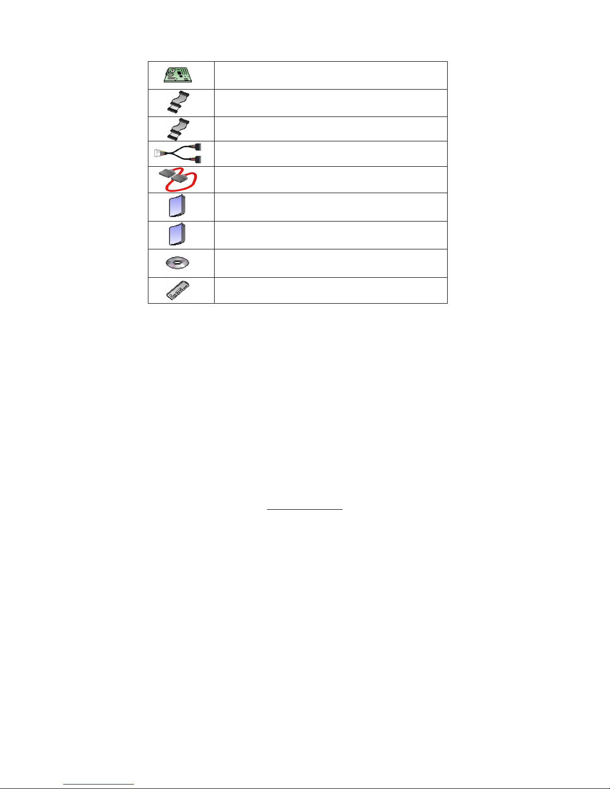
Check the box contents!
1x S5197 motherboard
1x 34-Pin floppy drive cable
1 x Ultra-DMA-133/100/66/33 IDE cable
2 x Serial ATA power cable
4 x Serial ATA cable
1 x S5197 user’s manual
1 x S5197 Quick Reference guide
1 x TYAN driver CD
1 x I/O shield
If any of these items are missing, please contact your vendor/dealer for
replacement before continuing with the installation process.
NOTE: The box contents do not include any driver diskette. Please use the
included driver CD to make a driver diskette. Refer to Appendix II for the
information on how to make a driver diskette.

4
http://www.tyan.com
NOTE

5
http://www.tyan.com
Chapter 1: Introduction
1.1 - Congratulations
You have purchased one of the most powerful server solutions. The Toledo
i3010W (S5197) is a flexible Intel® platform for multiple applications, based on Intel®
Mukilteo-2P MCH and ICH7-R chipsets.
Designed to support the family of Intel
®
Socket 775 processors and 8GB DDR2
533/667 memory, the S5197 has integrated Dual Gigabit Ethernet LAN, built-in
32MB ATI graphics controller and four SATA-II ports. This motherboard represents
the best choice for a server platform product.
Remember to visit TYAN’s Website at http://www.TYAN.com
. There you can find
information on all of TYAN’s products with FAQs, online manuals and BIOS
upgrades.
1.2 - Hardware Specifications
Processors
z Intel
®
Pentium 4 1066/800/533
MHz FSB
z Supports Intel® Celeron®D ,
Pentium® D, Pentium® 4,
Pentium® Extreme Edition,
Intel® Core™2 Duo processor
z Single Socket-T LGA775 socket
Expansion Slots
z Two PCI-X 133/100/66 slots in
one PCI-X bus
z One PCI-Express x16 slot with
PCI-Express x8 signals
z PCI-Express x4 slot with PCI-
Express x4 signals
z One 32bit/33MHz 3.3V PCI 2.2
slot
z Total five usable slots
Chipset
z NB: 3010 Mukilteo-2P MCH,
IOB: 6702 PXH-V; SB: ICH7R
z SMSC SCH5027 Super I/O chip
w/PECI support
System Management
z Supports Tyan M3291 SMDC
via 25x2 pin-header
z Integrated H/W Monitoring
functions in Super I/O chip with
PECI support
z One 4-pin CPU fan header and
four 4-pin system fan headers
z 2-pin chassis intrusion header
z Temperature and voltage
monitoring
Intelligent Platform Management
Interface Header
z Tyan M3291 Server
Management Daughter card
(Optional) supports features
listed below via IPMI header
z Based Renesas H8 2167
Baseboard Management
Controller (BMC)
z Tailored for IPMI 2.0
specifications
z Windows and Linux based
Management Solution
z Supports RMCP and SNMP
protocols

6
http://www.tyan.com
Memory
z Dual or single DDR-II memory
channels
z Four DDR-II 533/667 DIMM
sockets
z Supports up to 8 GB ECC or
non-ECC unbuffered memory
Integrated I/O
z One floppy connector for up to
two drives
z One IDE connector
z One COM port (via cable)
z One ECP/EPP/SPP parallel port
header (via an optional cable)
z Four USB v2.0 in USB Type A
(vertical) connectors
z Four SATAII ports
z One 2x25 connector for optional
TYAN SMDC card
Integrated PCI IDE
z Single ATA100/66 IDE bus
master channel supports up to 2
ATA/ATAPI IDE compliant drives
Integrated SATA Controller
(ICH7-R)*
z Supports 4 SATAII ports running
at 3.0Gb/s
z Support Raid 0/1/5/10
(*Note: the current version of the
ICH7R SATA RAID Utility can only
support Windows XP/2000/2003)
Onboard Graphics
z ATI ES1000 (a.k.a. RN50) VGA
graphics controller
z 32MB frame buffer
z I
2
C serial multi-master
controllers and UARTs
z Remote power on/off and reset
support (IPMI-over-LAN) on
Intel’s 82573
BIOS
z Phoenix BIOS 8Mb flash ROM
z Supports ACPI 1.0, PnP
z Auto detection of memory size
z Auto configuration of IDE hard
disk types
z User settings of hardware
monitoring
z Multiple boot options including
PXE or emulated FD/HD
z Power Management: S1, S3, S4
and S5
Back Panel I/O Ports
z One stacked Mouse/ Keyboard
connector
z One stacked four-port USB
connector
z One 9-pin COM Port
z One 15-pin VGA Port
z Two side-by-side GbE RJ45
Form Factor
z Standard ATX (12" x 9.6”)
z EPS/12V 24-pin plus 8-pin
power connectors
Power
z Onboard 5-phase CPU VRM
z One universal 24-pin EPS/12V
system power connector plus
one 8-pin power connector for
processor power

7
http://www.tyan.com
Integrated LAN Controller(s)
z Two 10/100/1000 Gigabit
Ethernet NIC
z Two Intel’s 82573 GbE NICs
(1*82573E & 1*82573V)
z Running at independent x1 PCI-
Express bus
Regulatory
z FCC Class B (Declaration of
Conformity)
z European Community CE
(Declaration of Conformity)
1.3 - Software Specifications
OS (Operating System) Support
Windows Server 2003 (R2 or later)
Red Hat Linux EL4
Red Hat Linux EL5
SuSE Enterprise Server 10
TYAN reserves the right to add support or discontinue support for any OS
with or without notice.

8
http://www.tyan.com
Chapter 2: Board Installation
You are now ready to install your motherboard. The mounting hole pattern of the
Toledo i3010W S5197 matches the ATX specification. Before continuing with
installation, confirm that your chassis supports an ATX motherboard.
How to install our products right… the first time
The first thing you should do is reading this user’s manual. It contains important
information that will make configuration and setup much easier. Here are some
precautions you should take when installing your motherboard:
(1) Ground yourself properly before removing your motherboard from the
antistatic bag. Unplug the power from your computer power supply and
then touch a safely grounded object to release static charge (i.e. power
supply case). For the safest conditions, TYAN recommends wearing a
static safety wrist strap.
(2) Hold the motherboard by its edges and do not touch the bottom of the
board, or flex the board in any way.
(3) Avoid touching the motherboard components, IC chips, connectors,
memory modules, and leads.
(4) Place the motherboard on a grounded antistatic surface or on the antistatic
bag that the board was shipped in.
(5) Inspect the board for damage.
The following pages include details on how to install your motherboard into your
chassis, as well as installing the processor, memory, disk drives and cables.
NOTE
DO NOT APPLY POWER TO THE BOARD IF IT HAS BEEN
DAMAGED
9
http://www.tyan.com
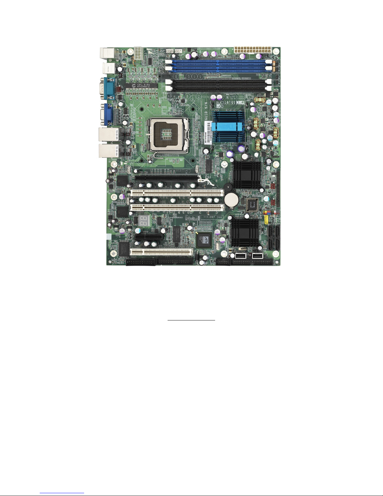
2.1- Board Image
This picture is representative of the latest board revision available at the
time of publishing. The board you receive may or may not look exactly
like the picture above.
10
http://www.tyan.com
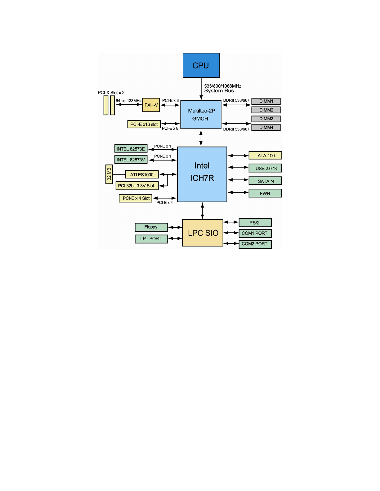
2.2 - Block Diagram
Toledo i3010W S5197
11
http://www.tyan.com
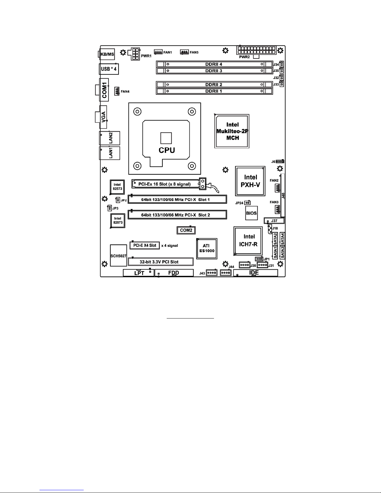
2.3 - Board Parts, Jumpers and Connectors
This diagram is representative of the latest board revision available at the time of
publishing. The board you receive may not look exactly like the diagram above.

12
http://www.tyan.com
2.4 – Jumper Settings
Jumper Function Settings
J3 COM1 Connector See Section 2.4.1
J5 COM2 Connector See Section 2.4.2
J6
External Speaker Header and Enable/Disable
Buzzer
See Section 2.4.3
J8 LPT Connector See Section 2.4.4
J30,J31
J43,J44
USB Header (4-Pin x 1) See Section 2.4.5
J37 Front Panel Header See Section 2.4.6
J32~J35
Front Panel LAN1/LAN2 Link and Active LED
Connector: J32 ~ J35
See Section 2.4.7
J40 ASF 2.0/SMDC Select See Section 2.4.8
JP1 Clear CMOS Jumper See Section 2.4.9
JP2,JP3 LAN1&LAN2 Enable/Disable Jumper See Section 2.4.10
JP24 PCI-X Frequency Configure See Section 2.4.11
FAN1~5 FAN Headers See Section 2.4.12
Jumper Legend
OPEN - Jumper OFF Without jumper cover
CLOSED - Jumper ON With jumper cover
To indicate the location of pin-1
To indicate the location of pin-1
13
http://www.tyan.com
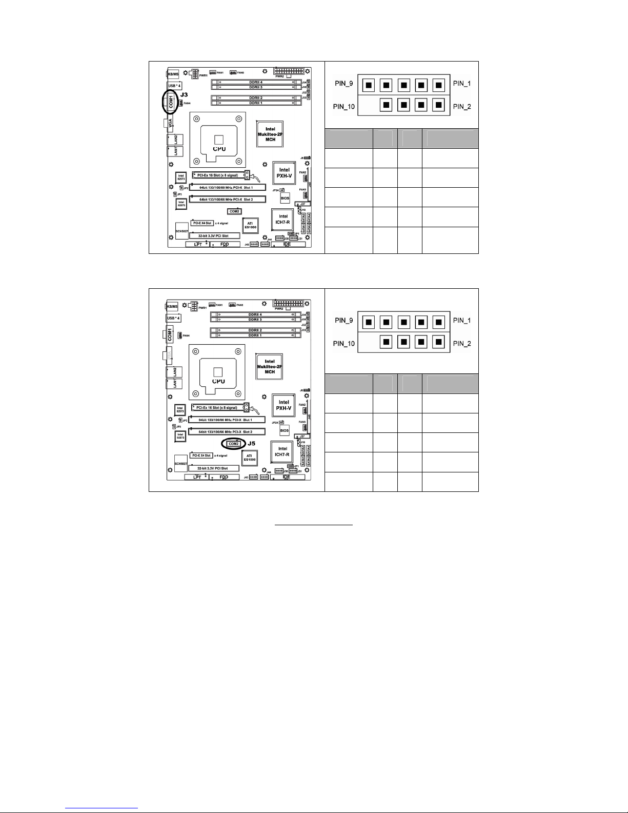
2.4.1 – COM1 Connector (J3)
Signal
Description
Pin # Pin # Signal
Description
DCD
1 2
DSR
RXD
3 4
RTS
TXD
5 6
CTS
DTR
7 8
RI
GND
9 10
KEY
2.4.2 – COM2 Connector (J5)
Signal
Description
Pin # Pin # Signal
Description
DCD2
1 2
DSR2
RXD2
3 4
RTS2
TXD2
5 6
CTS2
DTR2
7 8
RI2
GND
9 10
KEY
14
http://www.tyan.com
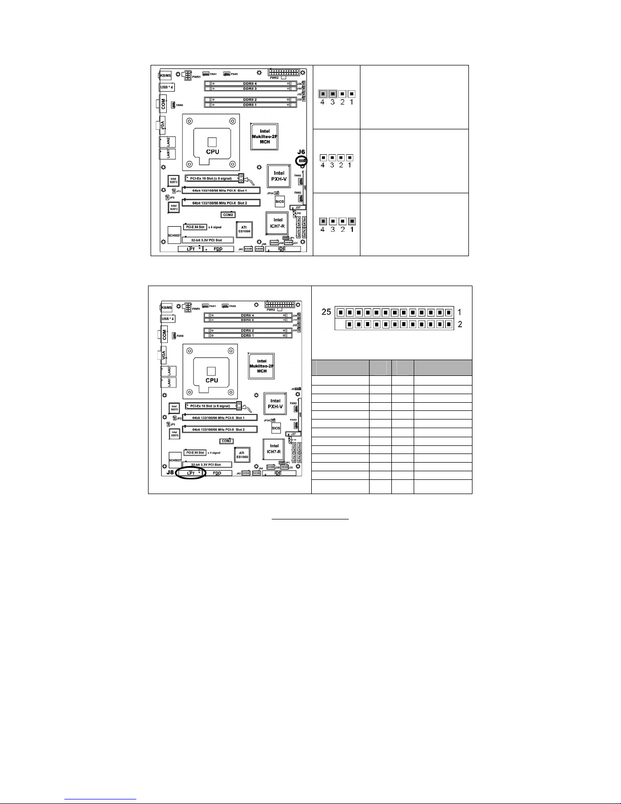
2.4.3 –External Speaker Header and Enable/Disable Buzzer (J6)
Enable onboard buzzer
Disable onboard buzzer
Pin 1 and Pin 4 for an
external speaker header
Pin 1: +5Vdc power
Pin 4: SPK_DATA
2.4.4 – LPT Connector (J8)
Signal
Configuration
PIN # PIN
#
Signal
Configuration
STB# 1 2 AFD#
LPD0 3 4 ERR#
LPD1 5 6 INIT#
LPD2 7 8 SLIN#
LPD3 9 10 GND
LPD4 11 12 GND
LPD5 13 14 GND
LPD6 15 16 GND
LPD7 17 18 GND
ACK# 19 20 GND
BUSY 21 22 GND
PE 23 24 GND
SLCT 25 26 KEY

15
http://www.tyan.com
2.4.5 –Vertical USB Header (4-Pin x 1) (J30, J31, J43, J44)
Pin_4: GND
Pin_3 : DATA +
Pin_2 : DATA -
Pin_1
Pin_1 : +5VPWR
2.4.6 – Front Panel Header (J37)
Signal
PIN # PIN
#
Signal
HD_
LED+
1 2
PW_
LED+
HD_
LED-
3 4
PW_ LED-
GND0
5 6
PWR_
S/W#
RESET
7 8
GND2
GND1
9 10
SLP_SW#/
WLED+
Ext.
Interrupt
11 12
GND3/
WLED-
+5VSB
13 14
NC
SMBUS
Data
15 16
GND4
The Front Panel Header is used to connect some control
or signal wires from motherboard to chassis, such as
HDD LED, power LED, power button, and reset button.
SMBUS
Clock
17 18
INTRU#
16
http://www.tyan.com
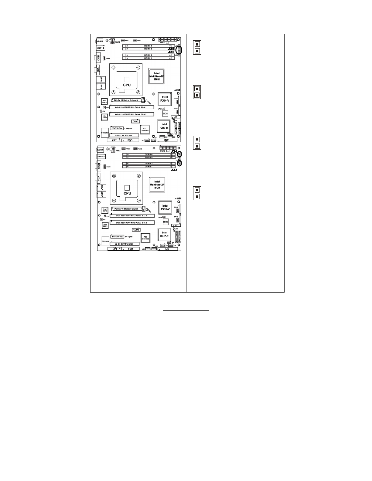
2.4.7 – Front Panel LAN1/LAN2 Link and Active LED Connector: J32 ~ J35
J35
1
J32
1
J35 is for connecting an
external LED to indicate LAN2
LINK and ACTIVITY. The
behavior of this LED is the
same as LAN2 RJ45 LED2:
Pin 1: LED+
Pin 2: LED-
J32 is for connecting an
external LED to indicate LAN1
LINK and ACTIVITY. The
behavior of this LED is the
same as LAN1 RJ45 LED2:
Pin 1: LED+
Pin 2: LED-
The external LED’s for J32 and J34
can be either bi-color or single-color
LED.
For a single-color LED to indicate
1000Mbps SPEED, connect Pin 1 to
LED+ and Pin 2 to LED-.
J34
1
J33
1
J34 is for connecting an
external LED to indicate LAN2
SPEED. The behavior of this
LED is the same as LAN2
RJ45 LED1:
Pin 1: 100 Mbps- (Low Active)
Pin 2: 1000 Mbps- (Low
Active)
J33 is for connecting an
external LED to indicate LAN1
SPEED. The behavior of this
LED is the same as LAN1
RJ45 LED1:
Pin 1: 100 Mbps- (Low Active)
Pin 2: 1000 Mbps- (Low
Active)
17
http://www.tyan.com
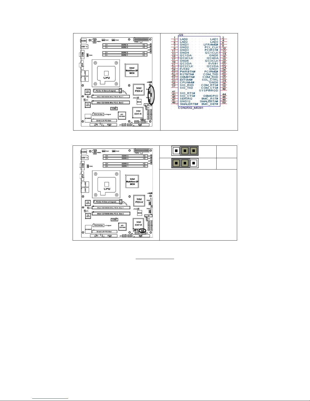
2.4.8 –SMDC CON25X2_M3291 (J40)
2.4.9– Clear CMOS Jumper (JP1)
Pin_3 Pin_1
Normal
Pin_3 Pin_1
Clear
You can reset the CMOS settings by using
this jumper if you have forgotten your
system/setup password or need to clear
system BIOS setting.
- Power off system and disconnect
both power connectors from the
motherboard
- Use jumper cap to close Pin_2 and
Pin_3 for several seconds to Clear
CMOS
- Put jumper cap back to Pin_1 and
Pin_2 (default setting)
Reconnect power & power on system
For connection with Tyan Server
Management Daughter Card (SMDC).
The SMDC connector is compatible with
only the Tyan M3291 (SMDC).
18
http://www.tyan.com
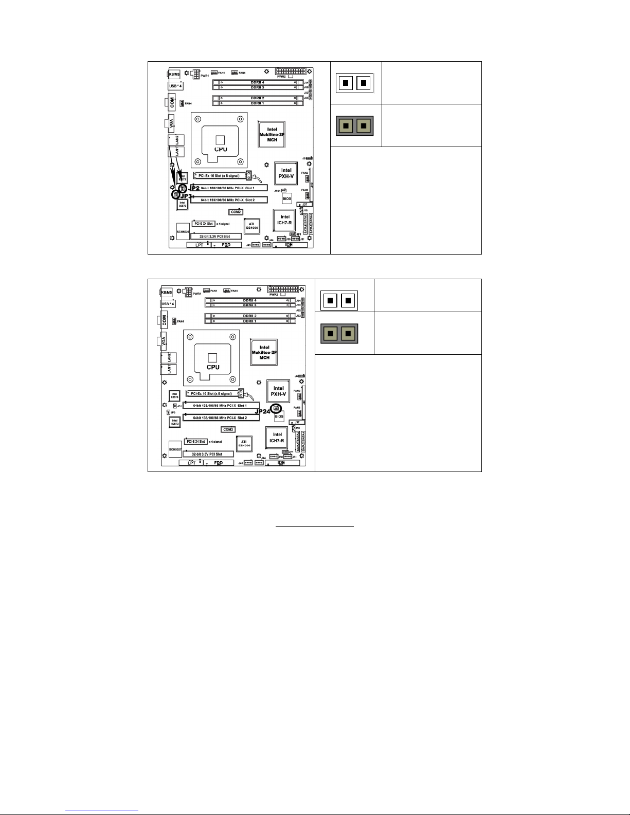
2.4.10 – LAN1 & LAN2 Enable / Disable Jumper (JP2, JP3)
OPEN - Enable
CLOSED– Disable
JP2: LAN1 Enable/Disable
JP3: LAN2 Enable/Disable
2.4.11 – PCI-X Frequency Configure (JP24)
OPEN - Jumper OFF
CLOSED - Jumper ON
JP24 is used to adjust PCI-X frequency.
Open(Default):133MHz/100MHz/66MHz;
Closed: 100MHz/66MHz
19
http://www.tyan.com
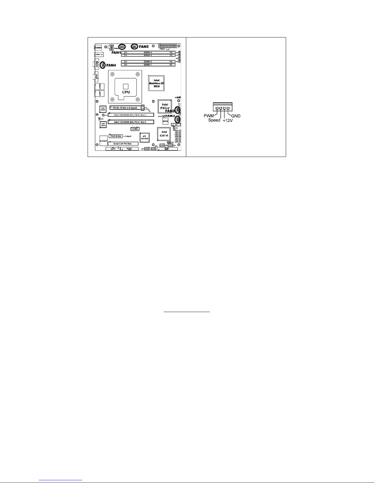
2.4.12 – FAN Headers
Use these headers to connect the 3-pin or 4-pin
cooling fans to your motherboard to keep the
system stable and reliable.
These connectors support the tachometer
monitoring and auto fan speed control.
FAN1: CPUFAN (4-pin)
FAN2,FAN3,FAN4,FAN5:System FAN (4-pin)

20
http://www.tyan.com
2.4.13 - OEM Reserved Connectors and Jumpers
The connectors and jumpers, which are not listed, are reserved for OEM use only.

21
http://www.tyan.com
2.5 - Tips on Installing Motherboard in Chassis
Before installing your motherboard, make sure your chassis has the necessary
motherboard support studs installed. These studs are usually metal and are gold
in color. Usually, the chassis manufacturer will pre-install the support studs. If
you are unsure of stud placement, simply lay the motherboard inside the chassis
and align the screw holes of the motherboard to the studs inside the case. If
there are any studs missing, you will know right away since the motherboard will
not be able to be securely installed.
Toledo i3010W S5197 Mounting Hole Placement
22
http://www.tyan.com
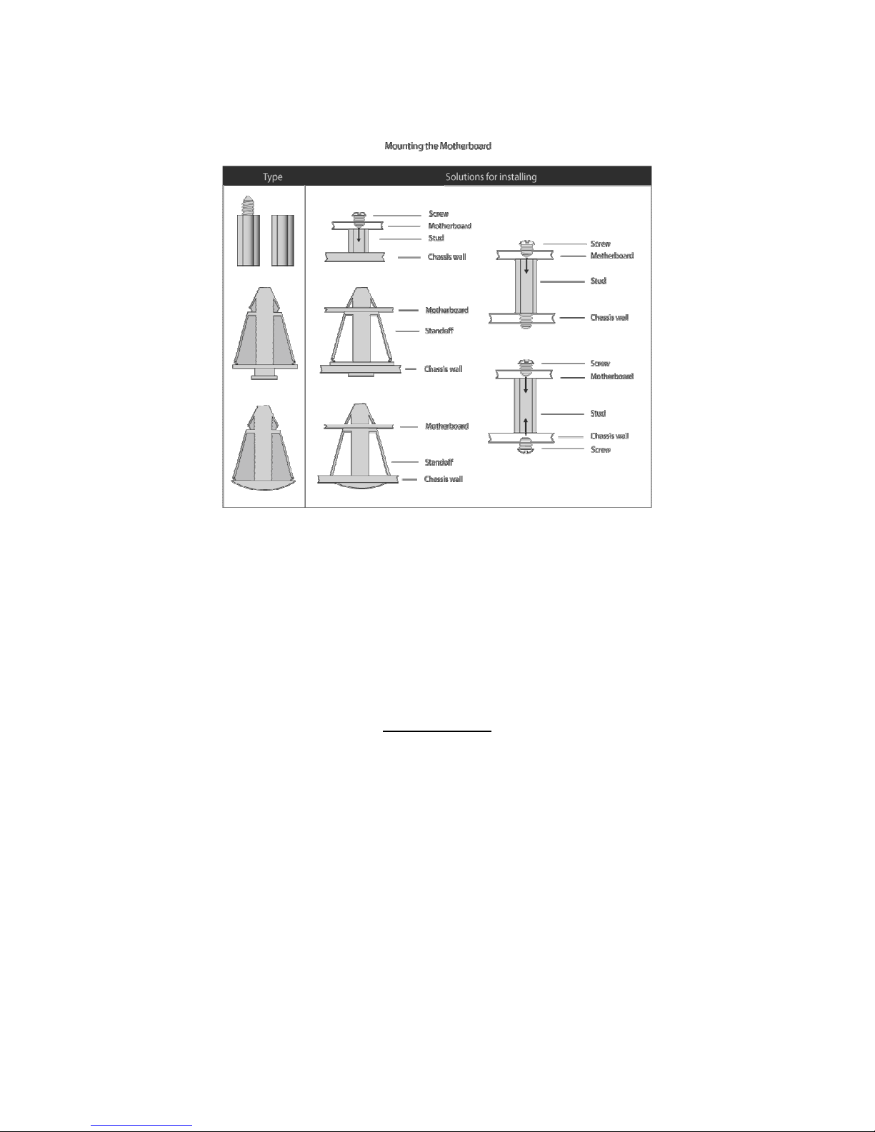
Some chassis’ include plastic studs instead of metal. Although the plastic studs
are usable, TYAN recommends using metal studs with screws that will fasten
the motherboard more securely in place.
Below is a chart detailing what the most common motherboard studs look like
and how they should be installed.
TIP: Use metal studs if possible, as they hold the motherboard into place more
securely than plastic standoffs.
23
http://www.tyan.com
2.6 - Installing the Memory
Before installing memory, ensure that the memory you have is compatible with the
motherboard and processor. Only DDRII-667/533 DIMM modules are required.
Check the TYAN Web site at: www.tyan.com for details of the type of memory
recommended for your motherboard.
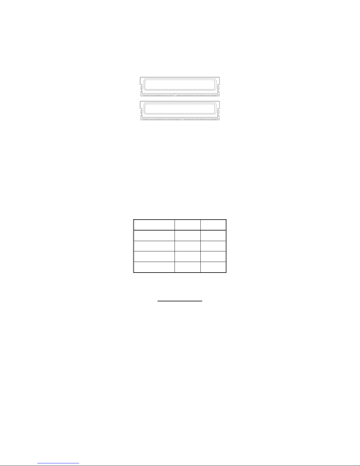
The following diagram shows common types of DDRII memory modules.
Key points to note before installing memory:
For optimal dual-channel DDRII operation, always install memory in
pairs beginning with DDRII2 and DDRII4. Memory modules of the same
type and density are required for dual-channel DDRII operation.
Mismatched memory may cause system instability.
• Only DDRII 667/533 un-buffered ECC/non-ECC memory modules are
supported.
• All installed memory will automatically be detected and no jumpers or
settings need changing.
Refer to the following table for supported DDRII populations.
(Note: X indicates a populated DIMM slot)
Population Option 1 2
DDRII1 x
DDRII2 x x
DDRII3 x
DDRII4 x x
24
http://www.tyan.com
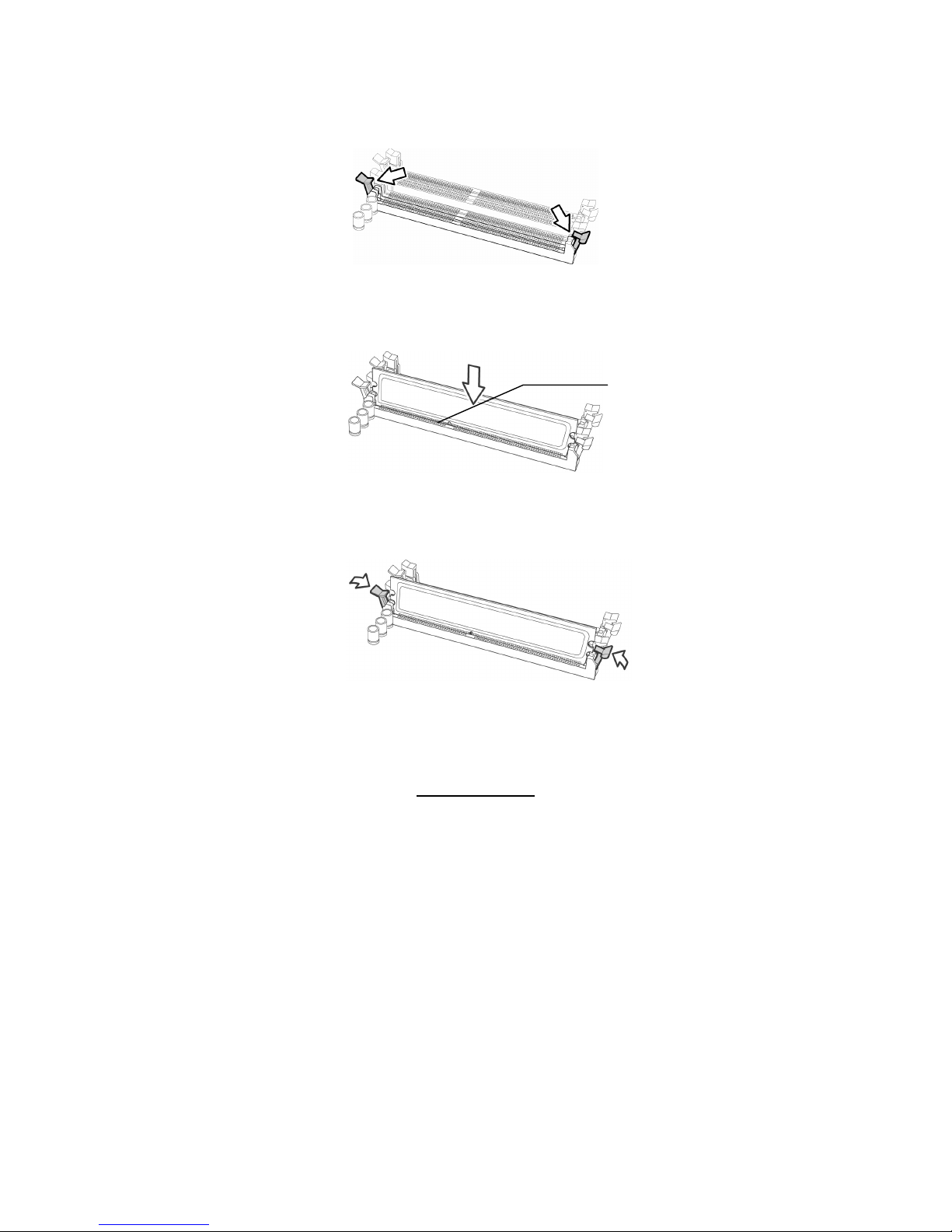
Memory Installation Procedure
Follow these instructions to install memory modules into the S5197.
1. Press the locking levers in the direction shown in the following illustration.
2. Align the memory module with the socket. The memory module is keyed to fit
only one way in the socket.
3. Seat the module firmly into the socket by gently pressing down until it sits
flush with the socket. The locking levers pop up into place.
Key slot
 Loading...