

TYAN Toledo i3000R S5191, S5191 User Manual

1
http://www.tyan.com
Toledo i3000R
///
S5191
Version 1.1
Copyright
Copyright © TYAN Computer Corporation, 2006. All rights reserved. No part of
this manual may be reproduced or translated without prior written consent from
TYAN Computer Corp.
Trademark
All registered and unregistered trademarks and company names contained in
this manual are property of their respective owners including, but not limited to
the following.
TYAN, Toledo i3000R are trademarks of TYAN Computer Corporation.
Intel, Prescott, and combinations thereof are trademarks of Intel Corporation.
Phoenix, Phoenix-AwardBIOS are trademarks of Phoenix Technologies.
Microsoft, Windows are trademarks of Microsoft Corporation.
SuSE,is a trademark of Novell.
IBM, PC, AT, and PS/2 are trademarks of IBM Corporation.
Notice
Information contained in this document is furnished by TYAN Computer
Corporation and has been reviewed for accuracy and reliability prior to printing.
TYAN assumes no liability whatsoever, and disclaims any express or implied
warranty, relating to sale and/or use of TYAN products including liability or
warranties relating to fitness for a particular purpose or merchantability. TYAN
retains the right to make changes to product descriptions and/or specifications
at any time, without notice. In no event will TYAN be held liable for any direct or
indirect, incidental or consequential damage, loss of use, loss of data or other
malady resulting from errors or inaccuracies of information contained in this
document.

2
http://www.tyan.com
Table of Contents
Check the box contents! 3
Chapter 1: Introduction
1.1 Congratulations 5
1.2 Hardware Specifications 5
Chapter 2: Board Installation
2.1 Board Image 8
2.2 Block Diagram 9
2.3 Board Parts, Jumpers and Connectors 10
2.4 Tips on Installing Motherboard in Chassis 20
2.5 Installing the Memory 21
2.6 Installing the Processor and Cooling Fan 23
2.7 Attaching Drive Cables 26
2.8 Installing Add-in Cards 28
2.9 Installing Optional SO-DIMM Modules 29
2.10 Connecting External Devices 30
2.11 Installing the Power Supply 31
2.12 Finishing Up 32
Chapter 3: BIOS Setup
3.1 About the BIOS 33
3.2 Main BIOS Setup 35
3.3 Main Menu 36
3.4 Advanced Menu 42
3.5 Security Menu 57
3.6 Power Menu 59
3.7 Boot Menu 60
3.8 Exit Menu 61
Chapter 4: Diagnostics
4.1 Beep Codes 63
4.2 Flash Utility 63
4.3 BIOS Post Code 64
Appendix I: SMDC Information
65
Appendix II: How to Make a Driver Diskette
69
Glossary
71
Technical Support
79
3
http://www.tyan.com
Check the box contents!
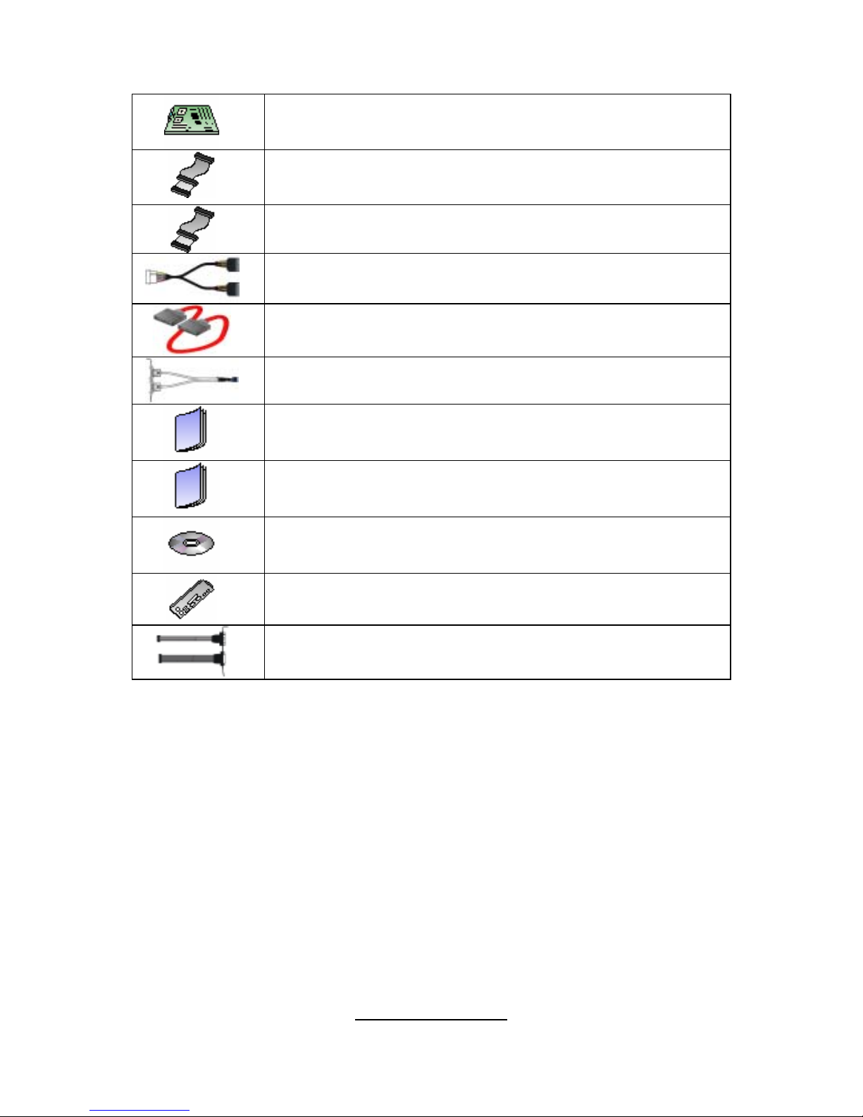
1x S5191 motherboard
1x 34-P i n floppy driv e c able
1 x Ultra-DMA-133/100/66/33 IDE cable
2 x Seri a l ATA power ca bles
4 x Serial ATA c a bles
1 x USB2.0 cable
1 x S5191 user’s manual
1 x S5191 Quick Reference guide
1 x TYAN driver CD
1 x I/O shield
1 x Seri a l & Parallel Port cabl e s e t
If any of these items are missing, please contact your vendor/dealer for
replacement before continuing with the installation process.
NOTE: The box contents do not include any driver diskette. Please use the
included driver CD to make a driver diskette. Refer to Appendix II for the
information on how to make a driver diskette.

4
http://www.tyan.com
NOTE

5
http://www.tyan.com
Chapter 1: Introduction
1.1 - Congratulations
You have purchased one of the most powerful server solutions available. The
Toledo i3000R (S5191) is a flexible Intel
®
platform for multiple applications,
based on the Intel
®
Mukilteo-2 MCH and ICH7-R chipsets.
Designed to support the family of Intel
®
Socket 775 processors and 8GB of
DDR2 533/667 memory. The S5191 has integrated Dual Gigabit Ethernet
LAN’s, a built-in 16MB XGI Volari Z7 (XG20) video controller and four SATA-II
ports. This motherboard represents the best choice for a server platform
product.
Remember to visit TYAN’s Website at http://www.TYAN.com
. There you can
find information on all of TYAN’s products with FAQs, online manuals and BIOS
upgrades.
1.2 - Hardware Specifica tions
Processor
• Single LGA775 sock et
• Support Intel
R
PentiumR 4 (Prescott -
2M/Cedar Mill), Pentium
R
D (Presler/
Smith Field [FSB 800MHz]), Intel
R
XeonR processor 3000 sequence
(Conroe), Intel
R
Extreme Edi t ion
(Presler XE/Conroe XE), Intel
R
CeleronR processor
• 533/8 00/1066MHz F SB
• Onboard VRM 11
Chipset
• IntelR Mukilteo-2 MCH
• ICH7-R South Bridg e
• PXH-V 64-bit PCI Hub
• SMSC SCH5027 Super I/O chip
Memory
• Four 240-pin DDR2 DIMM sockets
• Supports ECC DIM M s
• Maximum of 8GB non-reg/unbuffered
DDR2-533/667
Integrated Video Controller
• XGI Volari Z7 (XG20)
• 16MB frame buffer memory
Integrated SATA Controllers
(ICH7-R)
• Supports up to four SATA-II ports
running at 3.0Gb/s
• RAID 0/1/5/10 ca p a ble (Windows
driver support only)
Integrated LAN Controllers
• Two (2) Intel i82573V GbE LAN
controllers
-operating at P CIe x1 interface
• One (1) Intel i82551QM fast Ethernet
LAN controller
-operating at PCI 32-bit/3 3MHz
Expansion Slots
• One (1) PCI-X 64/133 slot in-line with
one (1) inversed PCIe x4 slot (routed
to PCIe x8 bus from the MCH)
• One (1) Tyan “TARO” SO-DIMM
socket
Integrated ATA-100 (ICH7-R)
• One ATA-100 channel for up to two
ATA-100 devices

6
http://www.tyan.com
System Management
• SMSC SCH5027 and EMC6D103
with hardware monitoring
• One (1) 3+1 - pi n CPU f an hea d e r w i th
tach ometer m onito ring and s mart
FAN control (by SCH5027)
• Five (5) 3+1-pin system fan headers
with tachometer monitoring, three (3)
of them support smart FAN control
• Temperature and voltage monitoring
• Watchdog timer support
• Port 80 code display LED
Integrated I/O
• One floppy connect or
• One IDE c o n nector
• Four SATA ports
• Six USB 2.0 ports (2 at rear, 4 via
cable)
• Two COM p o r ts (1 at rear, 1 vi a
cable)
• Tyan 2x9 front-panel pin header
• Tyan 2x6 front-panel pin header for
LAN LE D an d ID LE D/ Switch
• 2x25 connector for opt io nal Ty an
IPMI SMDC
Back Panel I/O Ports
• Stacked PS/2 mouse & keyboard ports
• Stacked 2 USB ports & 1 RJ45 10/100
ports
• One 9-p in COM po r t
• One 15-pin VGA port
• Two side-by-side RJ-45 10/100/1000
ports
Form Factor
• ATX footprint
• 12” x 9.6” (305mm x244mm)
Optional Modules
• M3291, IPMI 2.0 Remote System
Management card
-Renesas H8S2167 BMC controller
- BT, KCS, logging support
- IPMI-over-LAN
- Remote power on/off and reset
• M7901/M7902, Ultra320 SCSI
“TARO” card
-Adaptec AIC-7901/7902 single/dualchannel Ultra320 SCSI controller
- Adaptec HostRAID 0,1,10 supported
• M9000 SAS/SATA/SATA-II “TARO”
card
-Adaptec AIC-9405/AIC-9410 SAS
controller
- Supports up to 4-port (M9000-05RS) and 8-port (M9000-10-RS) SAS &
SATA r unning at 3.0G b / s
- Adaptec HostRAID 0, 1 & 10
supported
BIOS
• Phoenix BIOS on 8Mbit LPC Flash
ROM
• Serial C o nsole R e direct
• USB boot supported
• Supports APM1.2 and AC PI
• PnP, DMI2.0, WfM2.0 power
management
• S0/S 1/S4/S 5 states s upport e d
Power Supply
• EPS 12V
• Universal 24-pin + 8-pin power
connectors
Regulatory
• FCC Class B (DoC)
• European Community CE (DoC)
• BSMI
7
http://www.tyan.com
Chapter 2: Board Installation
You are now ready to install your motherboard. The mounting hole pattern of
the Toledo i3000R S5191 matches the ATX specification. Before continuing
with installation, confirm that your chassis supports an ATX motherboard.
How to install our products right… the first time
The first thing you should do is reading this user’s manual. It contains important
information that will make configuration and setup much easier. Here are some
precaut i ons you should take when installing your motherboard:
(1) Ground yourself properly before removing your motherboard from the
antistatic bag. Unplug the power from your computer power supply and
then touch a safely grounded object to release static charge (i.e. power
supply case). For the safest conditions, TYAN recommends wearing a
static safety wrist strap.
(2) Hold the motherboard by its edges and do not touch the bottom of the
board, or flex the board in any way.
(3) Avoid touching the motherboard components, IC chips, connectors,
memory modules, and leads.
(4) Place the motherboard on a grounded antistatic surface or on the
antistatic bag that the board was shipped in.
(5) Inspect the board for damage.
The following pages include details on how to install your motherboard into your
chassis, as well as installing the processor, memory, disk drives and cables.
NOTE
DO NOT APPLY POWER TO THE BOARD IF IT HAS BEEN
DAMAGED
8
http://www.tyan.com
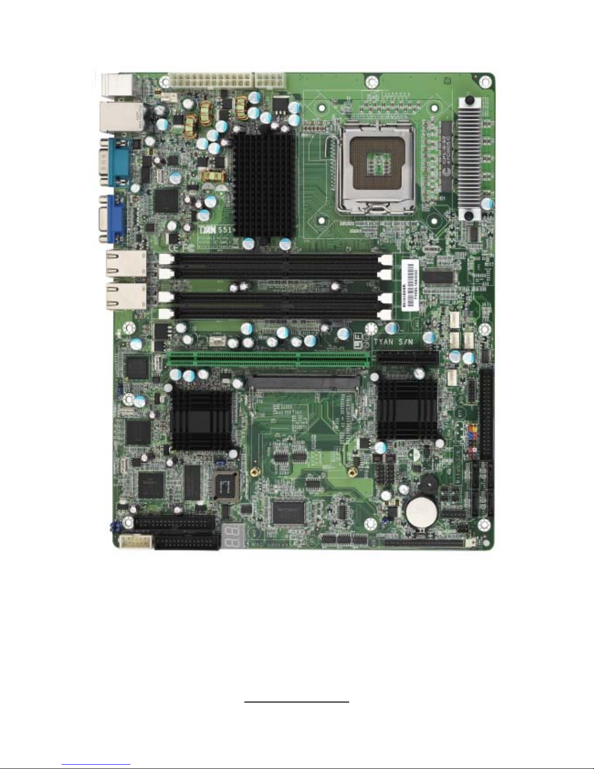
2.1- Board Image
This picture is representative of the latest board revision available at
the time of publishing. The board you receive may or may not look
exactly like the above picture.

9
http://www.tyan.com
2.2 - Block Diagram
Toledo i3000R S5191
10
http://www.tyan.com
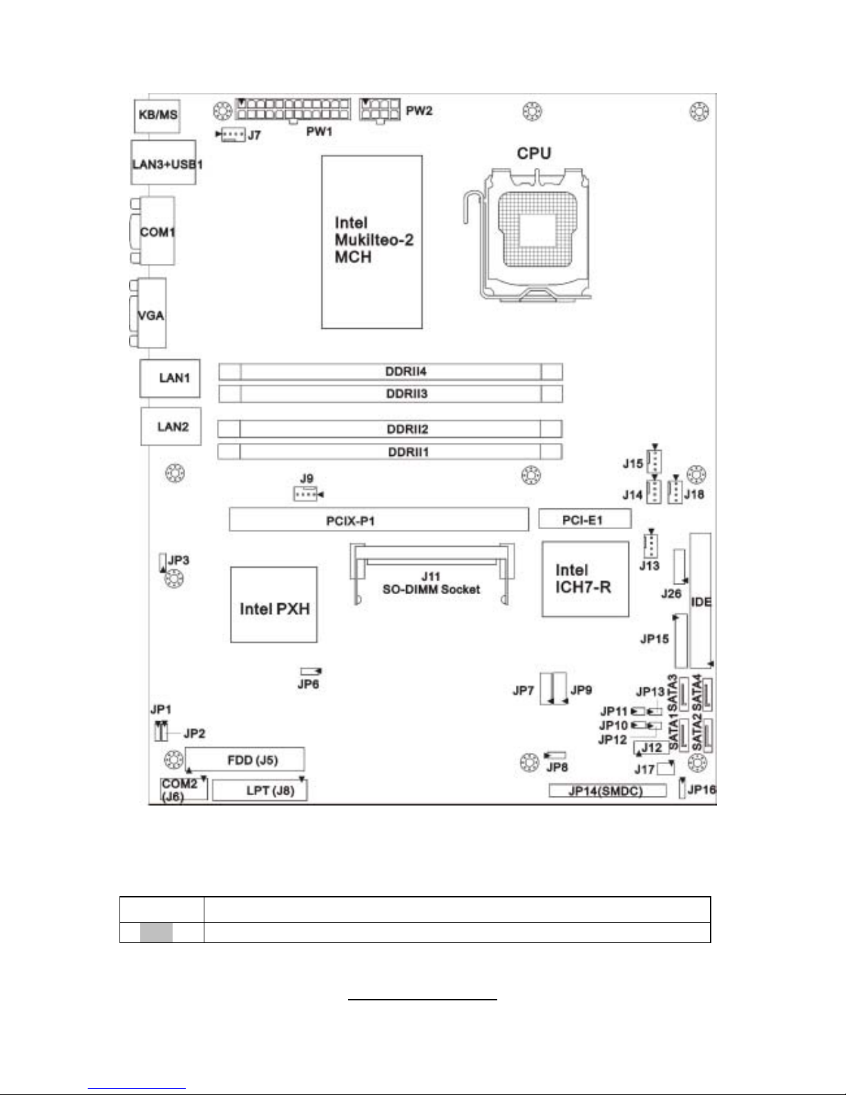
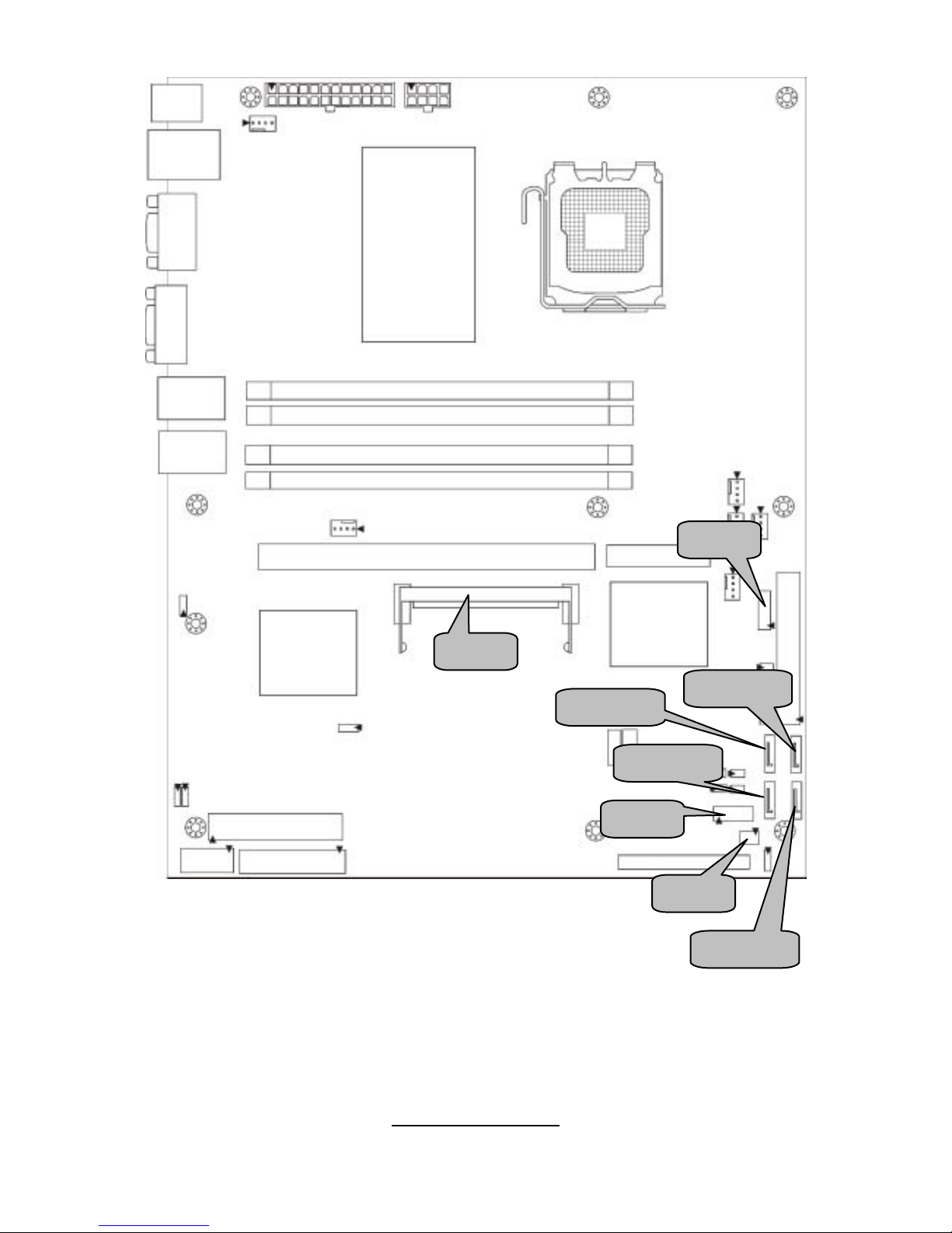
2.3 - Board Parts, Jumpers and Conn ec tors
This diagram is representative of the latest board revision available at the time of
publishing. The board you receive may not look exactly like the above diagram.
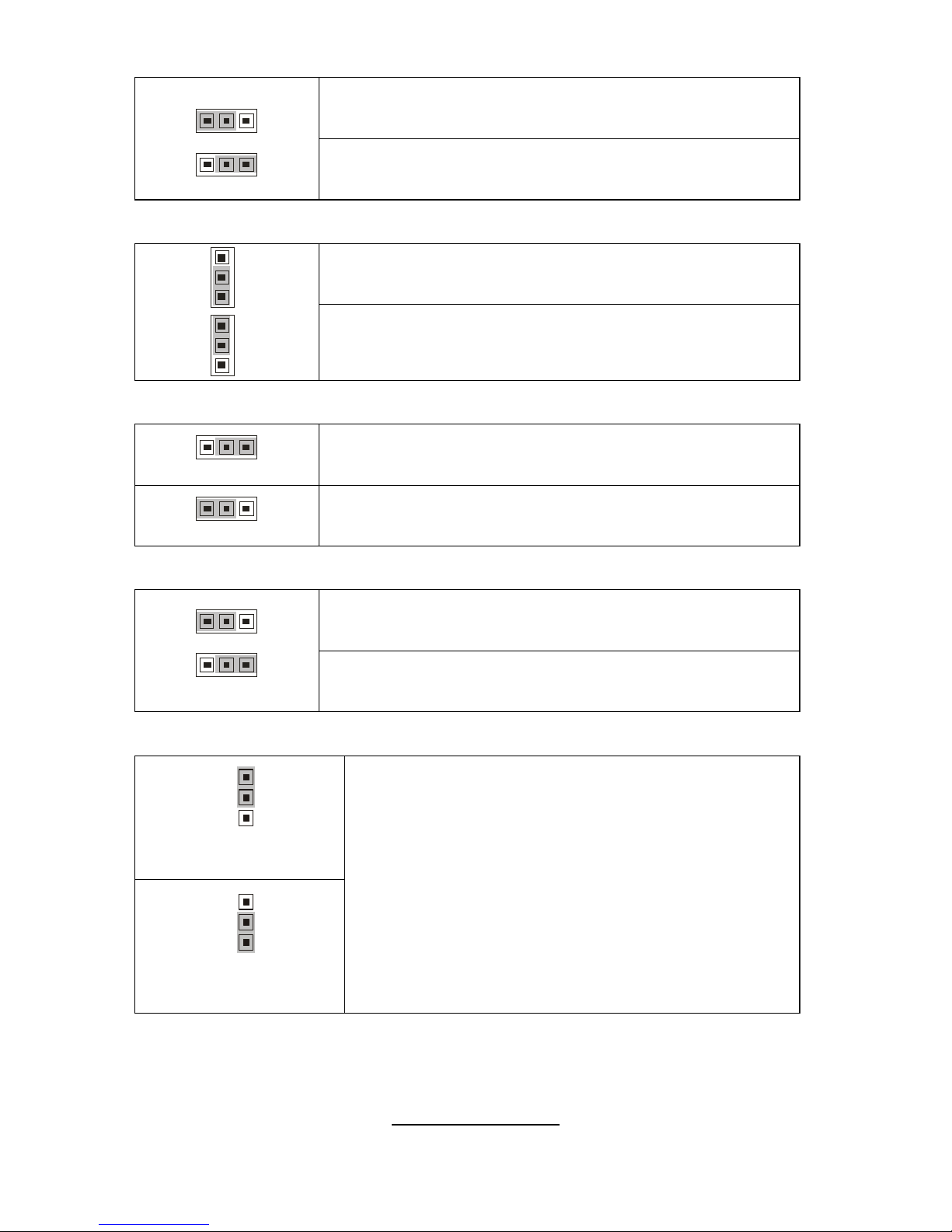
Jumper Legend
OPEN - Jumper OFF, without jumper cove r
CLOSED – Jumper ON, with jumper cover
11
http://www.tyan.com
Jumper/Connector Function
J6 COM2 Header
J7/J9 Chassis Fan Connector
J13/J14/J18 Front Fan Connector
J15 CPU_Fan Connector
J11 SO-DIMM Sock e t
J12 LED Connector (Reserved for OEM only)
JP14 SMDC Connector
JP15 Front Panel Header
JP7/JP9 Front Panel USB2.0 Connector
J17 LCM Connector
J5 FDD Connector
J8 LPT Connector
J26
Tachometer Connector
(Reserved for OEM only)
JP1/JP2 SMDC/ASF2.0 Select Header
JP3 LAN3 Enable/Disable Jumper
JP6 PCI-X Speed Select Header
JP16 Clear CMOS Jumper
JP8/JP10/JP11/JP12/JP13 Reserved for OEM only
12
http://www.tyan.com
J15
J13
J9
J18
J7
J14
JP15
13
http://www.tyan.com
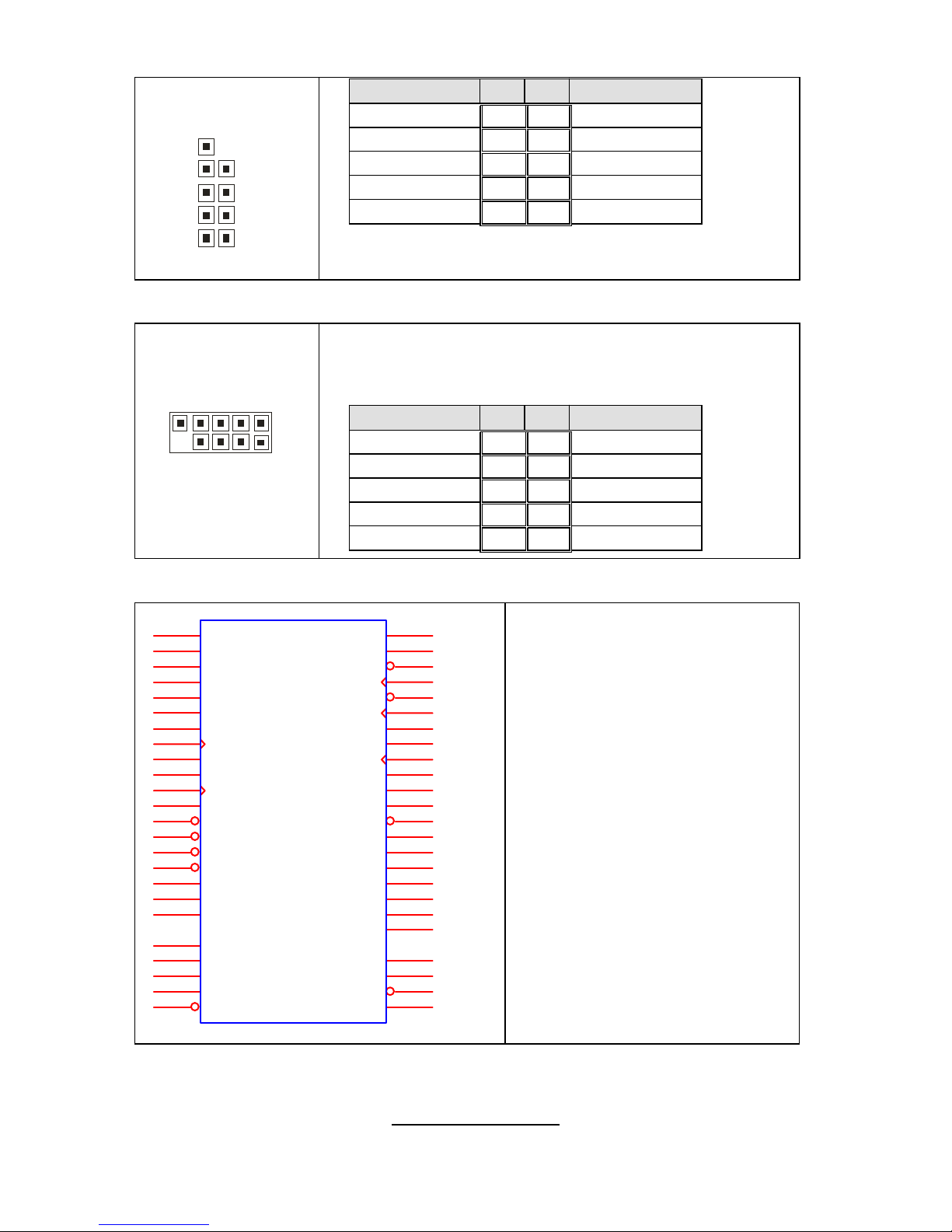
J13/J14/J15/J18: Fan Connector
4-pin Fan
+12V
PWM
GN
D
Tac hometer
1
3-pin Fan
Sp eed Control
NC
GND
Ta c ho m et er
1
Use these headers to connect the 3-pin or 4-pin
cooling fans to your motherboard to keep the
system stable and reliable.
J13: FAN3, J14: FAN1, J18: FAN2
J15: CPUFA N
These connectors support the tachometer
monitoring and auto fan speed control.
J7/J9: Chassis Fan Connector
+12
V
Full Speed Control
GND
Tach ome te
r
Use this header to connect the chassis cooling
fan to your motherboard to keep the system at
optimum performance levels.
J7: FAN 5, J9: FA N4
JP15: Front Panel Header
The Front Panel Header is used to connect some control or signal wires from
motherboard to chassis, such as HDD LED, power LED, power button, and
reset button.
HDD LED+ 1 2 Power LED+
HDD LED- 3 4 Power LED-
Reset SW- 5 6 Power SW+
Reset SW+ 7 8 Power SW-
External INT- 9 10 Warn ing LED+
External INT+ 11 12 Warning LED-
+5VSB 13 14 x
SMBUS Data
15 16
Chassis Intr# -(Active
Low)
SMBUS Clock
17 18
Chassis Intr# + (Active
Low)
14
http://www.tyan.com
JP9 JP7
JP14
J6
15
http://www.tyan.com
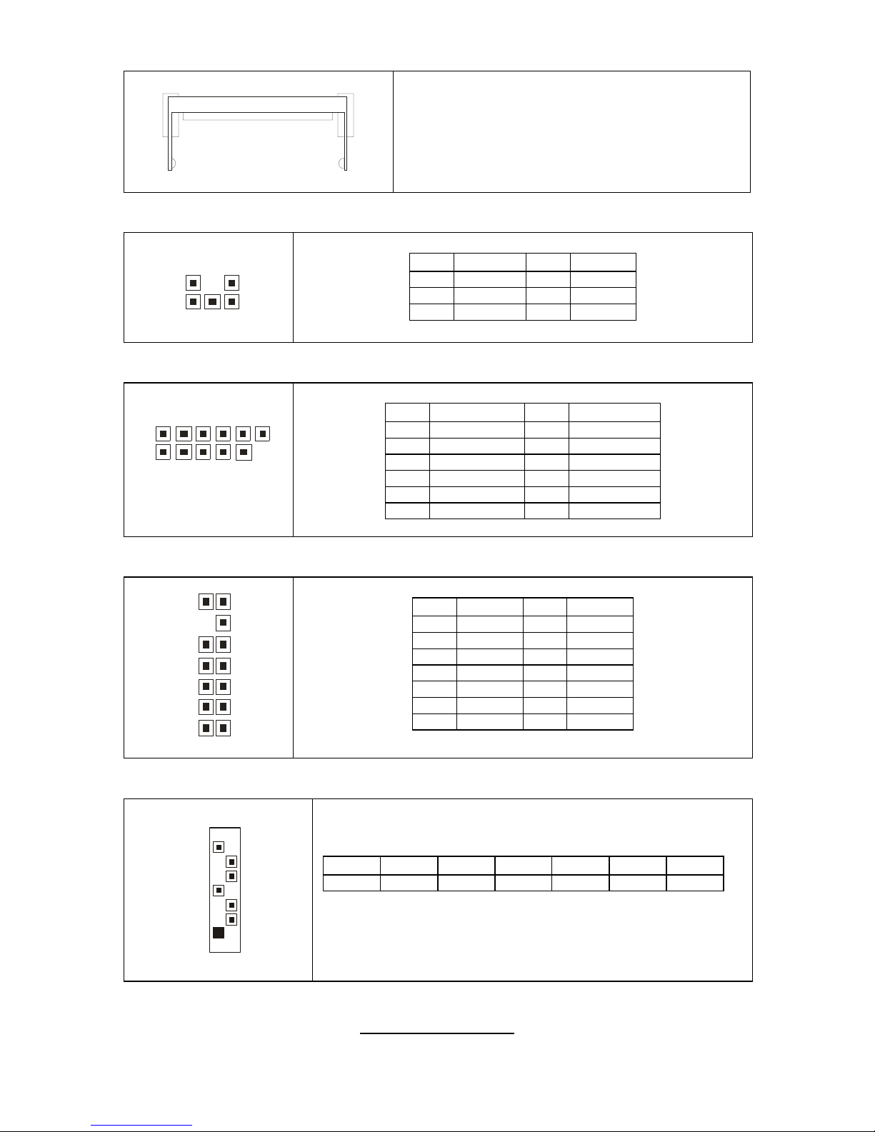
JP7/JP9: Front Panel USB2.0 Connector
1
0
2
9
1
Signal Pin Pin Signal
USB PWR
1 2
USB PWR
USB_A-
3 4
USB_B-
USB_A+
5 6
USB_B+
GND
7 8
GND
Key
9 10
NC
Use these headers to connect to the USB devices
via the enclosed USB cable.
J6: COM2 Header
10 2
9 1
Use these pin definitions to connect a port to COM2.
*TYAN does not provide cable for this header. It is designed for OEM
use only
.
Signal Pin Pin Signal
DCD
1 2
DSR
RXD
3 4
RTS
TXD
5 6
CTS
DTR
7 8
RI
GND
9 10
Key
JP14: SMDC Connector
LAD0
1
LAD2
3
GND1
5
GND2
7
GND3
9
GND4
11
I2C1DA
13
I2C4CLK
15
GND6
17
I2C3DA
19
I2C2CLK
21
5VSB2
23
PWRBTN#
25
RSTBTN#
27
OEMBTN#
29
EXTSMI#
31
CPUNMI#
33
SIO_RXD
35
SIO_TXD
37
SIO_RTS#
41
SIO_CTS#
43
SERIRQ
45
GND12
47
SMALERTB#
49
LAD1
2
LAD3
4
LFRAME#
6
PCI_CLK
8
PCIRST#
10
I2C1CLK
12
GND5
14
I2C4DA
16
I2C3CLK
18
5VSB1
20
I2C2DA
22
GND7
24
PCIPME#
26
COM_TXD
28
COM_RXD
30
SOL_CTRL
32
GND8
34
COM_RTS#
36
COM_CTS#
38
SYSPWRGD
40
OEMGPIO
44
BMC_RST#
46
SMALERTA#
48
BMC_DET#
50
JP14
CON25X 2_M3291
The SMDC connector allows you
to connect with the Tyan Server
Management Daughter Card
(SMDC). The S5191 supports
Tyan SMDC M3291. Refer to
Appendix I for more information
on SMDC.
16
http://www.tyan.com
J12
J17
J11
SATA3
SATA4
SATA2
J26
SATA1
17
http://www.tyan.com
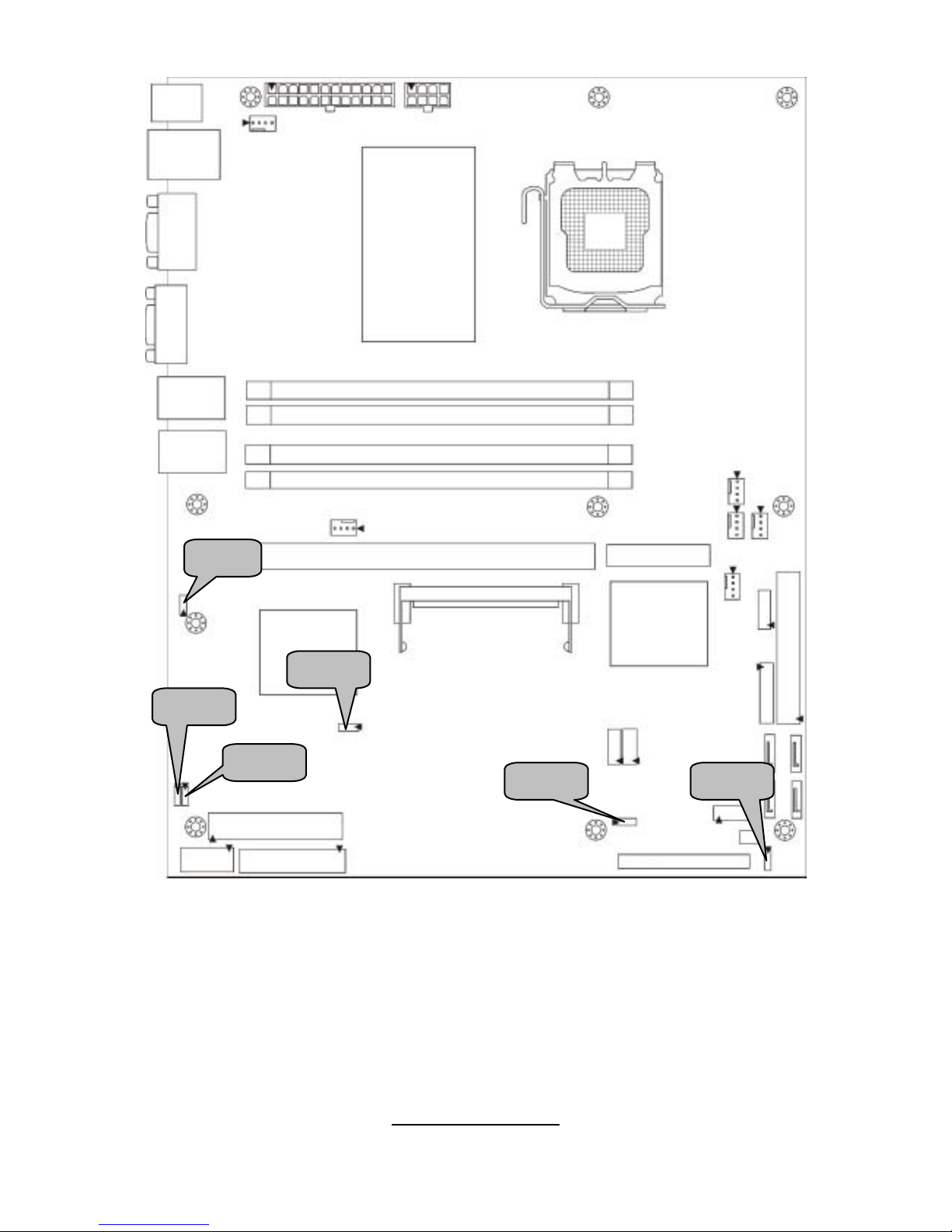
J11: Tyan SO-DIMM Connector
Use this connector to connect the Tyan
TARO card.
J17: LCM Header
5 1
6 2
Pin Signal Pin Si gnal
1 V5 2 RXD2
3 Key 4 GND
5 V5DUAL 6 TXD2
J12: LED Connector (Reserved for OEM only)
1 11
2 12
Pin Signal Pin Signal
1 LAN1_LED+ 2 LAN1_LED3 LAN2_LED+ 4 LAN2_LED5 LAN3_LED+ 6 LAN3_LED7 ID_LED+ 8 ID_LED9 ID_SW+ 10 ID_SW11 Key 12 NC
J26: Tachometer Connector (Reserved for OEM only)
13
14
1
2
Pin Signal Pin Signal
1 FAN1 2 FAN6
3 FAN2 4 NC
5 FAN3 6 NC
7 FAN4 8 NC
9 FAN5 10 NC
11 GND 12 Key
13 GND 14 PWM
SATA1/SATA2/SATA3/SATA4: SATA RAID Connector
7
1
Connects to the Serial ATA ready drives via the Serial
ATA cable.
Pin 1 Pin 2 Pin 3 Pin 4 Pin 5 Pin 6 Pin 7
GND TXP TXN GND RXN RXP GND
You may use any two of the four SATA ports to have the
support of RAID 0 and 1 through the onboar d I CH7R
south bridge chip.
18
http://www.tyan.com
JP3
JP2
JP8
JP6
JP1
JP16
19
http://www.tyan.com
JP1/JP2: SMDC/ASF2.0 Select Header
Pin 1-2 Closed: Enable ASF2.0 support (Default)
1
3
13
Pin 2-3 Closed: Enable SMDC card support
JP3: LAN3 Enable/Disable Jumper
Pin 1-2 Closed: Enable LAN3 (Default)
1
3
1
3
Pin 2-3 Closed: Disable LAN3
JP6: PCI-X Speed Select Header
31
Pin 1-2 Closed: 133MHz (Default)
3
1
Pin 2-3 Closed: 100MHz max.
JP8: PCI 3.3V/5V Select Header (Reserved for OEM only)
Pin 1-2 Closed: select 5V (Default)
1
3
13
Pin 2-3 Closed: select 3.3V
JP16: Clear CMOS Jumper
3
1
Normal
(Default)
3
1
Clear
Use this jumper when you have forgotten your
system/setup password or need to clear the system
BIOS settings.
How to clear the CMOS data
- Power off system and disconnect the power
supply from the AC source
- Use jumper cap to close Pin 2 and 3 for several
seconds to Clear CMOS
- Replace jumper cap to close Pin 1 and 2
Reconnect the power supply to the AC source
- Power on system
20
http://www.tyan.com
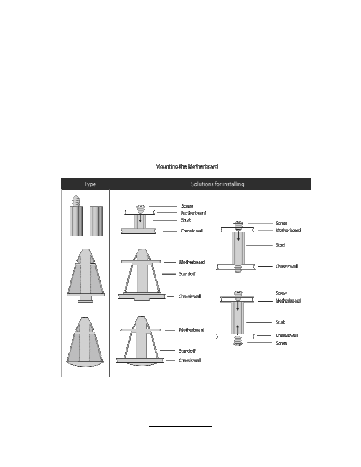
2.4 - Tips on Installing Motherboard in Chassis
Before inst al l ing your mother board, make s ur e you r chassis has th e
necessar y mot her board support studs ins t al l ed. Th e se stud s a re u sual l y
metal and are gold in color. Usually, the chassis manufacturer will pre-install
the support studs. If you are unsure of stud placement, simply lay the
motherboard inside the chassis and align the screw holes of the
motherboard to the studs inside the case. If there are any studs missing,
you will know right away since the motherboard will not be able to be
securely installed.
Some chassis’ include plastic studs instead of metal. Although the plastic
studs are usable, TYAN recommends using metal studs with screws that will
fasten the motherboard more securely in place.
Below is a chart detailing what the most common motherboard studs look
like and how they should be installed.
21
http://www.tyan.com
2.5 - Installing the Memory
Before installing memory, ensure that the memory you have is compatible with
the motherboard and processor. Only DDRII-533/667 DIMM modules are
required. Check the TYAN Web site at: www.tyan.com
for deta ils of the type of
memory recommended for your motherboard.
The following diagram shows common types of DDRII memory modules.
Key points to note before installing memory:
For optimal dual-channel DDRII operation, always install memory in
pairs beginning with DDRII1 and DDRI I3. Memor y modules of the
same type and density are required for dual-channel DDRII
operation. Mismatched memory may cause system instability.
• Only DDRII 533/667 un-buffered ECC/non-ECC memory modules are
supported.
• All installed memory will automatically be detected and no jumpers or
settings need changing.
Refer to the following table for supported D DRII populations.
(Note: X indicates a popu lat ed DI MM slot )
Population Option 1 2
DDRII1 x x
DDRII2 x
DDRII3 x x
DDRII4 x

22
http://www.tyan.com
Memory Installation Procedure
Follow these instructions to install memory modules into the S5191.
1. Press the locking levers in the direction shown in the following illustratio n.
2. Align the memory module with the socket. The memory module is keyed
to fit only one way in the socket.
3. Seat the module firmly into the socket by gently pressing down until it sits
flush with the socket. The locking levers pop up into place.
Key slot
23
http://www.tyan.com
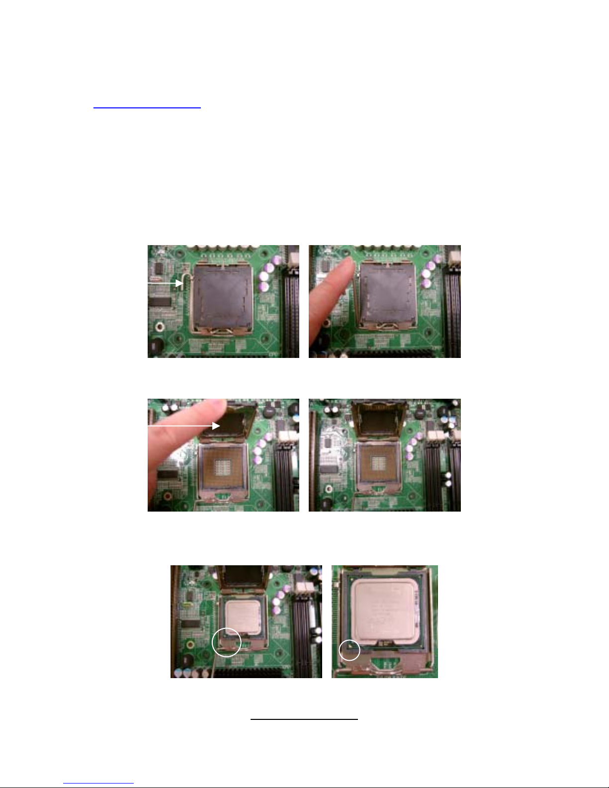
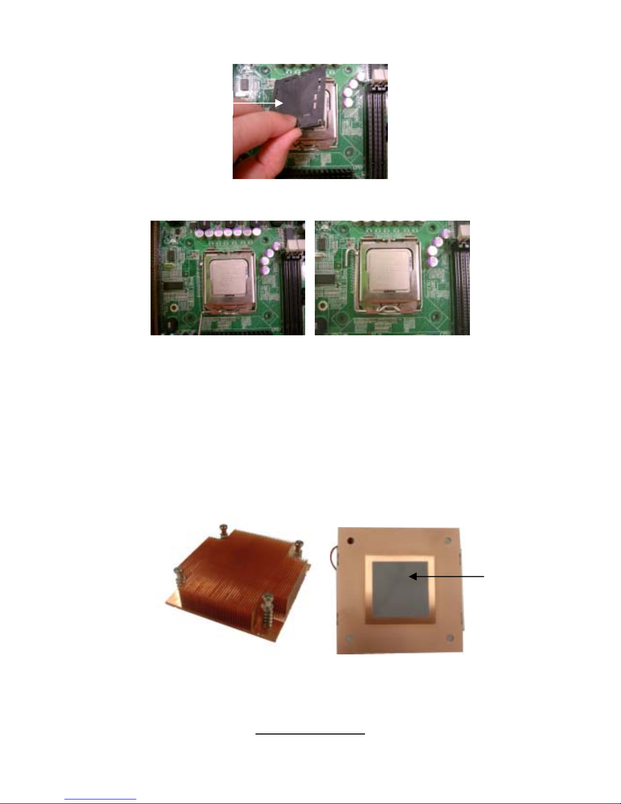
2.6 - Installing the Processor and Cooling Fan
Your Toledo i3000R S5191 supports the latest processor technologies from
Intel. Check the TYAN website for latest processor support:
http://www.tyan.com
Processor Installation (LGA 775 Socket)
The processor should be installed carefully. Make sure you are wearing an
antistatic strap and handle the processor as little as possible.
Follow these instructions to install your processor and heat sink.
1. Locate the processor socket on the motherboard and lift the locking lever
to a fully open position.
2. Lift the load plate to a fully open posit ion.
3. Inser t the processor into the socket and make sure that pin 1 is correctly
located.
locking
lever
load
p
late
Pin 1
identifie
r
24
http://www.tyan.com
4. Remove the PnP cap from the load plate.
5. Replace the load plate and return the locking lever to the locking position.
6. The CPU installation is now complete.
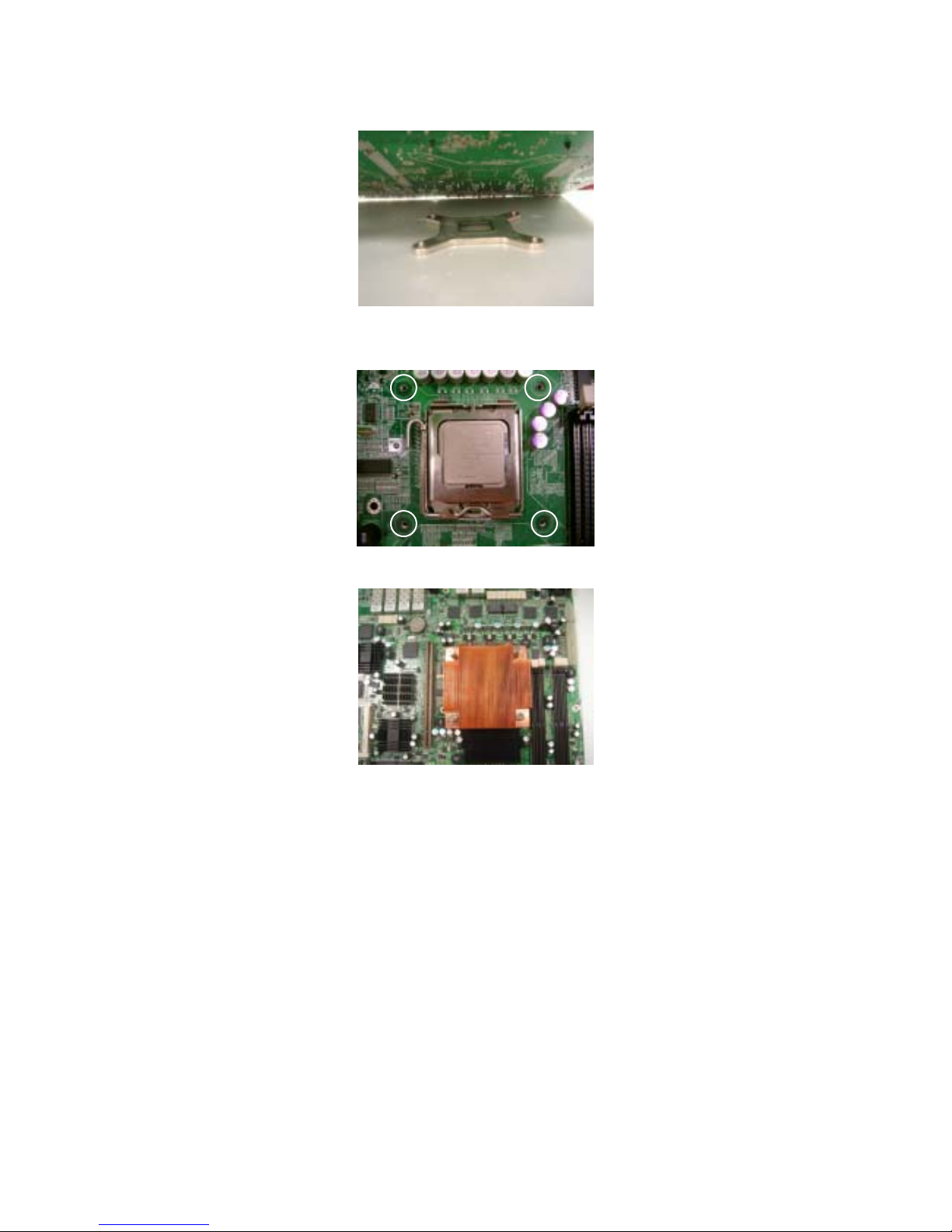
Cooling Fan Installation
After you have installed the processor, the heatsink should be installed to
ensure that the processor runs efficiently and does not overheat. Use the
heatsink supplied for best results.
Follow these instructions to install the heatsink shown.
1. Take out the heatsink from the package. Turn the heatsink upside down
and you can see that the heatsink has already applied a layer of thermal
compound.
PnP cap
thermal
compound
25
http://www.tyan.com
2. Turn the board upside down and insert the heat sink spring mechanism as
shown.
3. Align the heatsink with the four holes around the processor socket.
4. Press the heatsink down until the four screws are securely seated in the holes.
5. Use screw drive to secure the four screws.
 Loading...