

TYAN TOMCAT I7230W, Tomcat i7230W S5162, S5162 User Manual

Tomcat i7230W
///
S5162
Version 1.0
Copyright
Copyright © TYAN Computer Corporation, 2006. All rights reserved. No part of
this manual may be reproduced or translated without prior written consent from
TYAN Computer Corp.
Trademark
All registered and unregistered trademarks and company names contained in
this manual are property of their respective owners including, but not limited to
the following.
TYAN, Tomcat i7230W are trademarks of TYAN Computer Corpor ation.
Intel, Prescott, and combinations thereof are trademarks of Intel Corporation.
Phoenix, Phoenix-AwardBIOS are trademarks of Phoenix Technologies.
Microsoft, Windows are trademarks of Microsoft Corporation.
SuSE,is a trademark of SuSE AG.
IBM, PC, AT, and PS/2 are trademarks of IBM Corporation.
Notice
Information contained in this document is furnished by TYAN Computer
Corporation and has been reviewed for accuracy and reliability prior to printing.
TYAN assumes no liability whatsoever, and disclaims any express or implied
warranty, relating to sale and/or use of TYAN products including liability or
warranties relating to fitness for a particular purpose or merchantability. TYAN
retains the right to make changes to product descriptions and/or specifications
at any time, without notice. In no event will TYAN be held liable for any direct or
indirect, incidental or consequential damage, loss of use, loss of data or other
malady resulting from errors or inaccuracies of information contained in this
document.
1
http://www.tyan.com

2
http://www.tyan.com
Table of Contents
Check the box contents! 3
Chapter 1: Introduction
1.1 Congratulations…………………………………………………………… 4
1.2 Hardware Specifications………………………………………………… 4
1.3 Software Specifications…………………………………………............. 6
Chapter 2: Board Installation
2.1 Board Image……………………………………………………………… 8
2.2 Block Diagram……………………………………………………………. 9
2.3 Board Parts, Jumpers and Connectors………………………………... 10
2.4 Tips on Installing Motherboard in Chassis…………………………….. 20
2.5 Installing the Processor & Cooling Fan………………………………... 21
2.6 Installing the Memory……………………………………………………. 25
2.7 Attaching Drive Cables………………………………………………….. 27
2.8 Connecting External Devices…………………………………………… 29
2.9 Installing the Power Supply……………………………………………... 30
2.10 Finishing Up………………………………………………………………. 31
Chapter 3: BIOS Setup
3.1 About the BIOS…………………………………………………………… 33
3.2 BIOS Main Menu…………………………………………………………. 34
3.3 Advanced Menu………………………………………………………….. 42
3.4 Security Menu…………………………………………………………….. 60
3.5 Power Menu………………………………………………………………. 61
3.6 Boot Menu………………………………………………………………… 63
3.7 Exit Menu…………………………………………………………………. 64
Chapter 4: Diagnostics
4.1 Beep Codes………………………………………………………………. 65
4.2 Flash Utility……………………………………………………………….. 65
4.3 BIOS Post Code………………………………………………………….. 66
Appendix I: SMDC Information
Appendix II: How to Make a Driver Diskette
Glossary

Check the box contents!
1x S5162 motherboard
1x 34-Pin floppy drive cable
1 x Ultra-DMA-133/100/66/33 IDE cable
2 x Serial ATA power cable
4 x Serial ATA cable
1 x USB2.0 cable
1 x S5162 user’s manual
1 x S5162Quick Reference guide
1 x TYAN driver CD
1 x I/O shield
1 x Serial & Parallel Port cable set
If any of these items are missing, please contact your vendor/dealer for
replacement before continuing with the installation process.
NOTE: The box contents do not include any driver diskette. Please use the
included driver CD to make a driver diskette. Refer to Appendix II for the
information on how to make a driver diskette.
3
http://www.tyan.com

4
http://www.tyan.com
Chapter 1: Introduction
1.1 - Congratulations
You have purchased one of the most powerful server solutions. The Tomcat
i7230W (S5162) is a flexible Intel
®
platform for multiple applications, based on
Intel
®
E7230 (Mukilteo) MCH and ICH7-R chipsets.
Designed to support the family of Intel
®
Socket 775 processors and 8GB DDR2
667/533/400 memory. The S5162 has integrated Dual Gigabit Ethernet LA N,
built-in 16MB XGI XG20
TM
video and four serial ATA ports. This motherboard
represents the best choice for a server platform product.
Remember to visit TYAN’s Website at
http://www.TYAN.com. There you can
find information on all of TYAN’s products with FAQs, online manu als and BIOS
upgrades.
1.2 - Hardware Specifications
Processor
•Single LGA775 socket
•Support Intel
®
Pentium® D (dual-
core) /Prescott/Cedar Mill
processor
•1066/800/533 MHz FSB
Chipset
•Intel
®
E7230 (Mukilteo) MCH
•ICH7-R South Bridge
•6700PXH 64-bit PCI Hub
•SMSC SCH5017 Super I/O chip
Memory
•Four 240-pin DDR2 DIMM sockets
•Supports ECC DIMMs
•Maximum of 8GB unbuffered
(Non-Reg) DDR2-667/533/400
Expansion Slots
One (1) PCI-E X16 slot routed to
PCI-E X8 bus from MCH
Two (2) PCI 32-bit, 33MHZ slots
from ICH7-R
Three (3) PCI-X slots from PXH
One (1) PCI-X 64-bit, 133MHZ slots
Integrated Video Controller
XGI XG20
PCI interface
16MB frame buffer memory
Integrated ATA-100 (ICH7-R)
•One ATA-100 channel for up to
two ATA-100 devices
Integrated SATA Controllers
(ICH7-R)
•Supports four SATA-II ports
running at 3.0Gb/s
•RAID 0/1/5/10 capable (Windows
Driver CD support only)
Integrated LAN Controllers
One (1) Intel
®
i82573E GbE LAN
controllers
-operating at PCIe x1 interface
-With Intel AMT support (82573E
only)
One (1) Intel
®
i82573V GbE LAN
controller
-operating at PCIe x1 interface

5
http://www.tyan.com
from PCI-X bus B
Two (2) PCI-X 64-bit, 133/100MHZ
slots from PCI-X Bus A
System Management
SMSC SCH5017 and EMC6D103
with hardware monitoring
One (1) 3+1-pin CPU fan headers
with tachometer monitoring and
smart FAN control (by SCH5017)
Four (4) 3+1-pin system fan
headers with tachometer
monitoring, three (3) of them
support smart FAN control
Temperature and voltage
monitoring
Watchdog timer support
Port 80 code display LED
Integrated I/O
One floppy connector
One IDE connector
Four SATA ports
One ECP/EPP/SPP parallel port
(via cable)
Two USB 2.0 ports (via cable)
One COM port (via cable)
Tyan 2x9 front-panel pin header
Tyan 2x6 front-panel pin header for
LAN LED and ID LED/Switch
2x25 connector for optional Tyan
IPMI SMDC
Back Panel I/O Ports
•Stacked PS/2 mouse & keyboard
ports
•Stacked 4 USB ports
•One 9-pin COM port
•One 15-pin VGA port
•Two side-by-side RJ-45
10/100/1000 ports
Optional Modules
M3291, IPMI 2.0 Remote System
Management card
-Renesas H8S2167 BMC controller
- BT, KCS, logging support
- IPMI-over-LAN
- Remote power on/off and reset
BIOS
Phoenix BIOS on 8Mbit Flash ROM
or SPI Flash ROM
Serial Console Redirect
USB boot supported
Supports APM1.2 and ACPI
PnP, DMI2.0, WfM2.0
S0/S1/S3/S4/S5 states supported
Power Supply
•EPS12V
•24-pin + 8-pin power connectors
Form Factor
ATX footprint
12” x 9.6” (305mm x244mm)
Regulatory
FCC Class B (DoC)
European Community CE (DoC)
BSMI
*8GB not validated at time of print.

6
http://www.tyan.com
1.3 - Software Specifications
OS (Operating System) Support
Microsoft Windows 2000 SP4
Microsoft Windows XP SP2 (32-bit)
Microsoft Windows XP SP1 (64-bit)
Microsoft Windows Server 2003 SP1(32-bit & 64-bit)
SUSE LINUX Enterprise Server 9.0 SP2 (32-bit & 64-bit)
SUSE LINUX Professional 9.3 (32-bit & 64-bit)
RHEL3 Update 5 (32-bit & 64-bit)
RHEL4 Update 1 (32-bit & 64-bit)
TYAN reserves the right to add support or discontinue support for any OS with
or without notice.
7
http://www.tyan.com
Chapter 2: Board Installation
You are now ready to install your motherboard. The mounting hole pattern of
the Tomcat i7230W S5162 matches the ATX specification. Before continuing
with installation, confirm that your chassis supports an ATX motherboard.
How to install our products right… the first time
The first thing you should do is reading this user’s manual. It contains important
information that will make configuration and setup much easier. Here are some
precautions you should take when installing your motherbo ard:
(1) Ground yourself properly before removing your motherboard from the
antistatic bag. Unplug the power from your computer power supply and
then touch a safely grounded object to release static charge (i.e. power
supply case). For the safest conditions, TYAN recommends wearing a
static safety wrist strap.
(2) Hold the motherboard by its edges and do not touch the bottom of the
board, or flex the board in any way.
(3) Avoid touching the motherboard components, IC chips, connectors,
memory modules, and leads.
(4) Place the motherboard on a grounded antistatic surface or on the
antistatic bag that the board was shipped in.
(5) Inspect the board for damage.
The following pages include details on how to install your motherboard into your
chassis, as well as installing the processor, memory, disk drives and cables.
NOTE
DO NOT APPLY POWER TO THE BOARD IF IT HAS BEEN
DAMAGED

2.1- Board Image
This picture is representative of the latest board revision available at
the time of publishing. The board you receive may or may not look
exactly like the above picture.
8
http://www.tyan.com
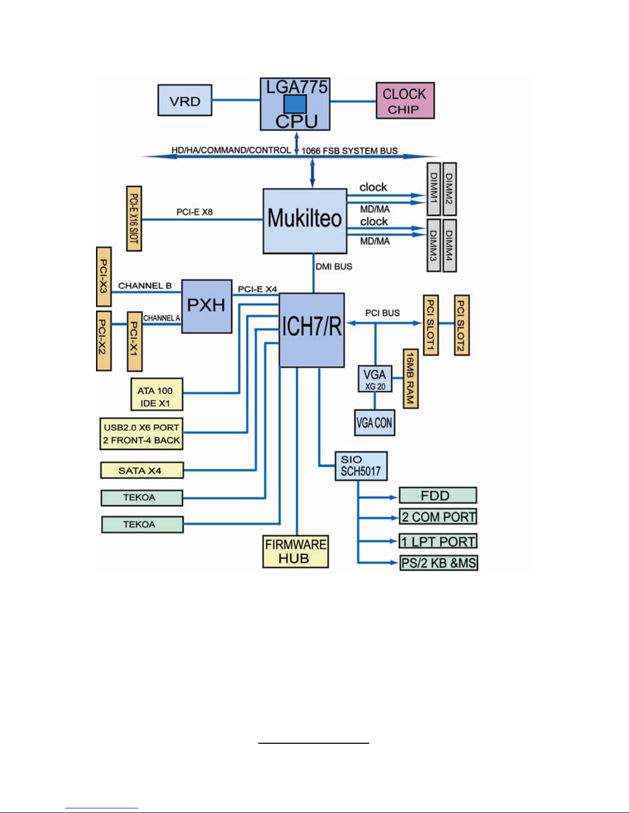
2.2 - Block Diagram
Tomcat i7230W S5162
9
http://www.tyan.com
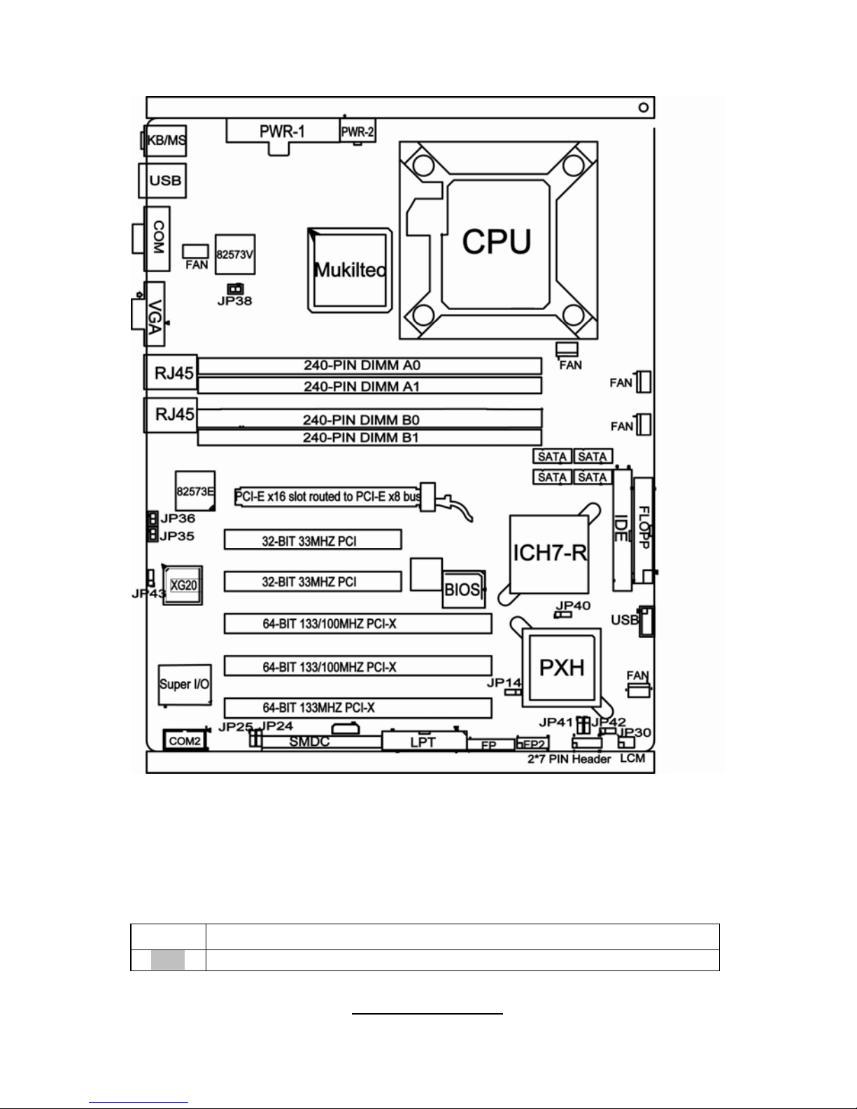
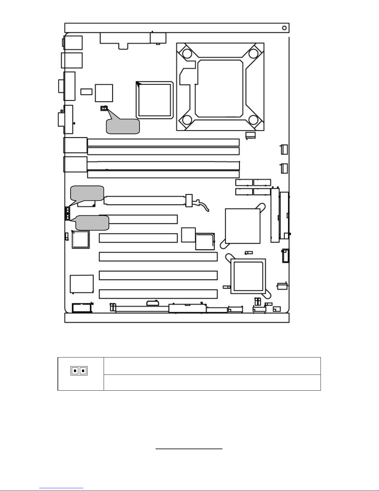
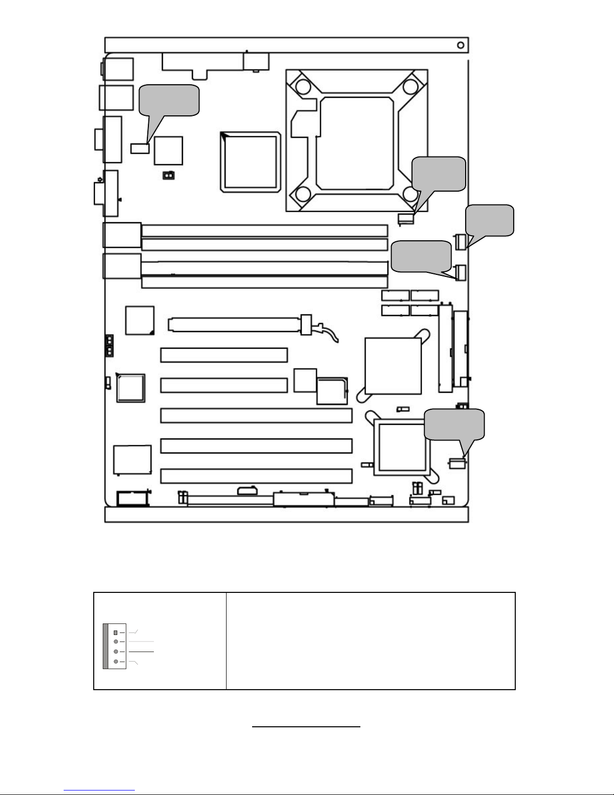
2.3 - Board Parts, Jumpers and Connectors
This diagram is representative of the latest board revision available at the time of
publishing. The board you receive may not look exactly like the above diagram.
Jumper Legend
OPEN - Jumper OFF, without jumper cover
CLOSED – Jumper ON, with jumper cover
10
http://www.tyan.com

11
http://www.tyan.com
Jumper/Connector Function
JP14 PXH Channel A speed setting
JP16 Front Panel Header
JP24/JP25 SM BUS Select
JP30 CMOS Clear
JP35 82573E SPI Shared Select
JP36
82573E NVM (Non-Volatile Memory) Protection
Select
JP38
82573V NVM (Non-Volatile Memory) Protection
Select
JP40 PXH Channel B speed setting
JP41 PXH Channel A PCI BUS speed setting
JP42 PXH Channel B PCI BUS speed setting
JP43 Onboard VGA controller Enable/Disable select
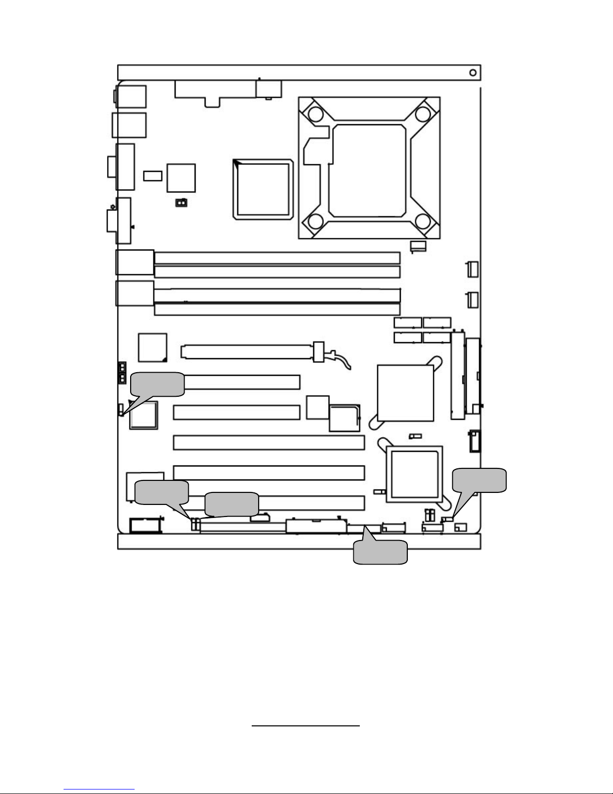
JP43
JP30
JP25
JP24
JP16
12
http://www.tyan.com

JP16: Front Panel Header
The Front Panel Header is used to connect some control or signal wires from
motherboard to chassis, such as HDD LED, power LED, power button, and
reset button.
13
http://www.tyan.com
HLED+
1 2
PLED+
HLED-
3 4
PLED-
GND
5 6
PWR SW+
Reset SW+
7 8
PWR SW-
VCC
9 10
SLP/Warning LED+
NMI
11 12
SLP/Warning LED-
+5VSB
13 14
N/A
SDA
15 16
GND
SMBUS Clock
17 18
INTRU#
JP30: Clear CMOS Jumper
3
1
Normal
(Defaut)
3
1
Clear
Use this jumper when you forgot your system/setup
password or need to clear system BIOS setting.
How to clear the CMOS data
- Power off system and disconnect the power
supply from the AC source
- Use jumper cap to close Pin 2 and 3 for
several seconds to Clear CMOS
- Replace jumper cap to close Pin 1 and 2
Reconnect the power supply to the AC source
- Power on system
JP24/JP25: SM BUS Select
1-2: Connect LAN SM BUS to mother board SM BUS
1
3
13
2-3: Connect LAN SM BUS to SMDC SM BUS
JP43 Onboard VGA controller Enable/Disable select
1-2: Enable by HW
1
3
13
2-3: Enable/Disable by BIOS
JP38
JP36
JP35
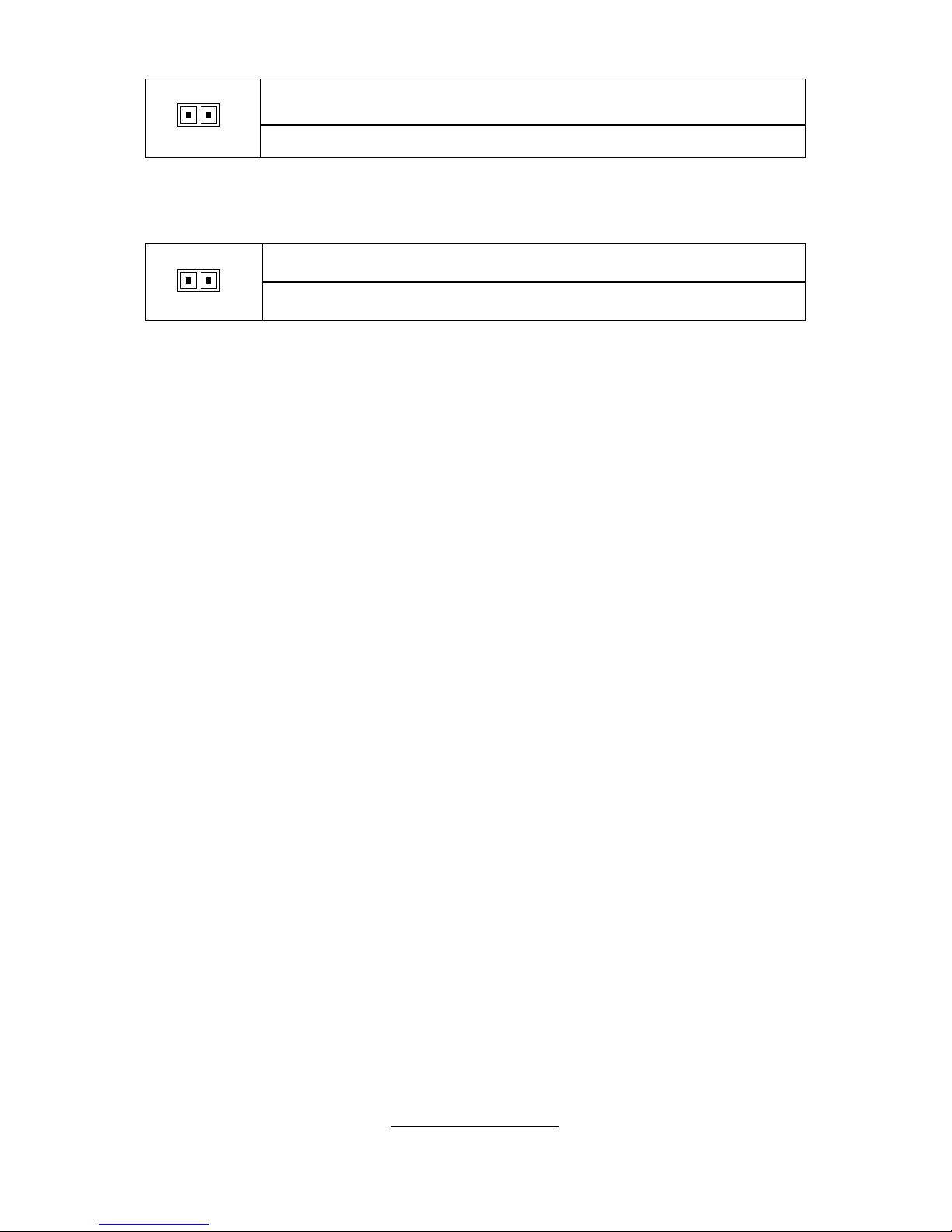
JP35 82573E SPI Shared Select
1-2 Off: Not shared SPI
1 2
1-2 On: shared SPI
JP36 82573E SPI Shared Select
14
http://www.tyan.com
1-2 Off: Protection Enable
1 2
1-2 On: Protection Disable
JP38: 82573V NVM(Non-Volatile Memory) Protection Select
1-2 Off: Protection Enable
1 2
1-2 On: Protection Disable
15
http://www.tyan.com
JP40
JP14
JP42
JP41
16
http://www.tyan.com
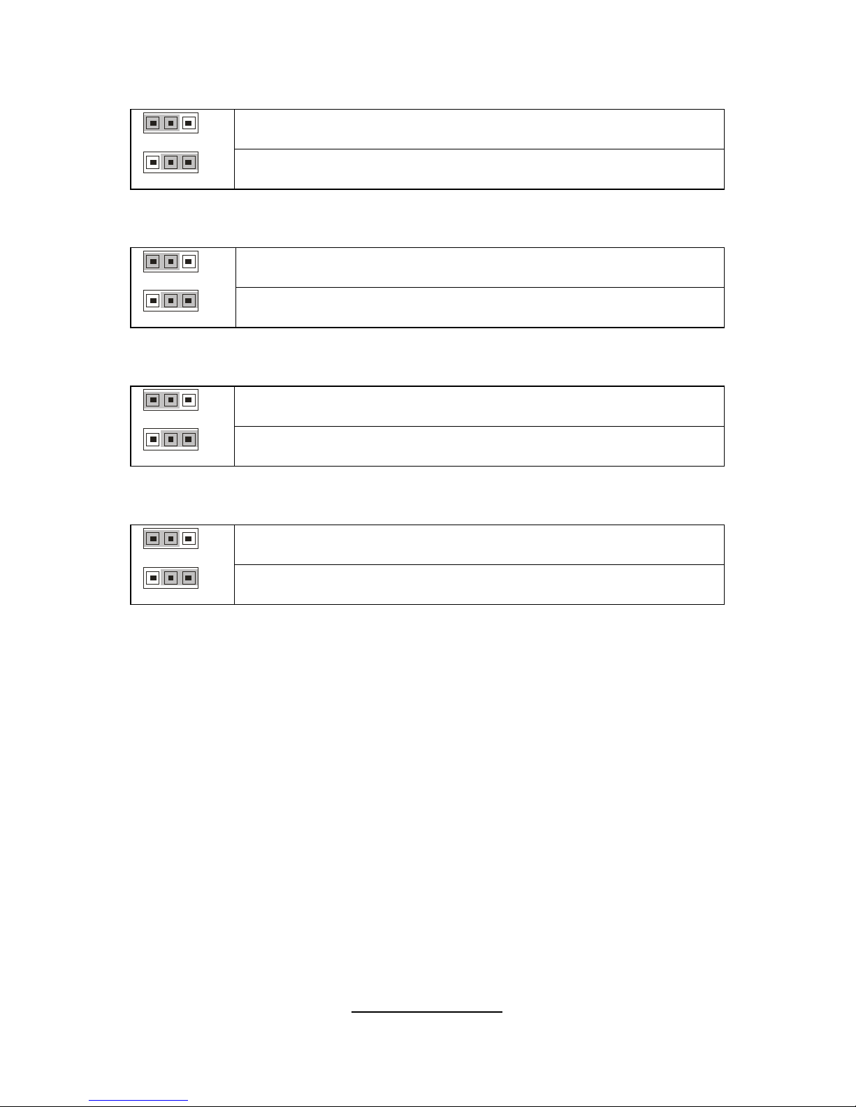
JP14: PXH Channel A speed setting
1-2: Enable 133MHz
1
3
13
2-3: Disable 133MHz
JP40: PXH Channel B speed setting
1-2: Enable 133MHz
1
3
13
2-3: Disable 133MHz
JP41: PXH Channel A PCI BUS speed setting
1-2: Selected by plug-in card
1
3
13
2-3: set to 33MHz
JP42: PXH Channel B PCI BUS speed setting
1-2: Selected by plug-in card
1
3
13
2-3: set to 33MHz
17
http://www.tyan.com
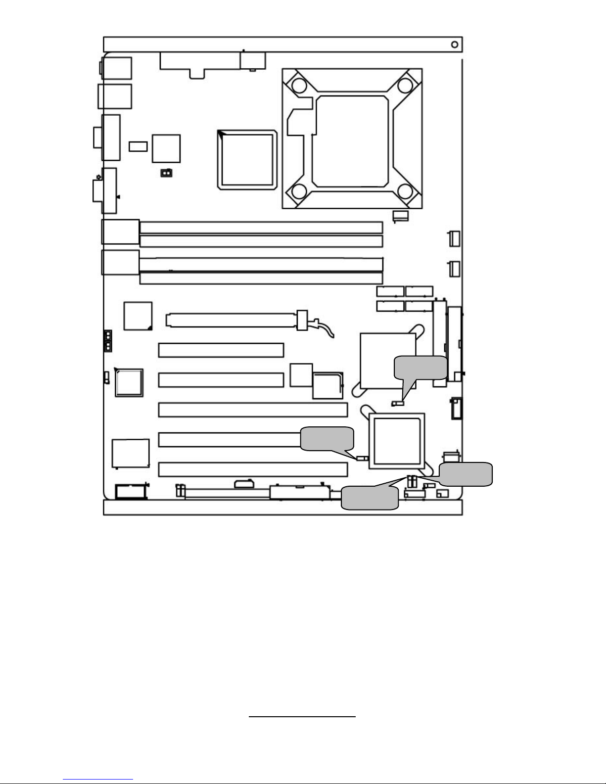
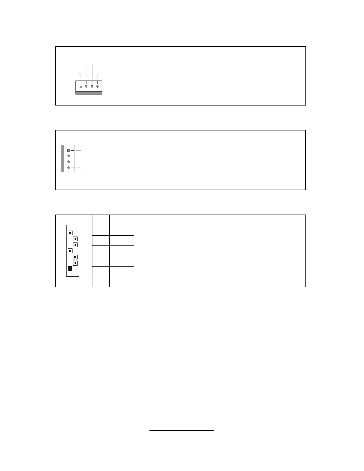
JP22
JP22: Front Fan Connector
Speed C ont rol
S peed C on trol
GND
Tachometer
Use these headers to connect the chassis cooling
fans to your motherboard to keep the system stable
and reliable.
These connectors support the tachometer
monitoring and auto fan speed control.
JP23
JP17
JP8
JP31
18
http://www.tyan.com
JP8/JP17: Chassis Fan Connector
+12V
5V
GND
Tachometer
Use this header to connect the chassis cooling fan
to your motherboard to keep the system at optimum
performance levels.
J31: CPU_FAN Connector
Speed C ont rol
S peed C on trol
GND
Tachometer
Use this header to connect the processor cooling
fan to your motherboard to keep the system stable
and reliable.
This connector supports the tachometer monitoring
and auto fan speed control.
J20,J21,J22,J23: Serial ATA RAID Connector
7 GND
6 RXP
5 RXN
4 GND
3 TXN
2 TXP
7
1
1 GND
Connects to the Serial ATA ready drives via the
Serial ATA cable
J20: SATA1 J21: SATA3
J22: SATA2 J23: SATA4
You can use any of the four Serial ATA ports for
RAID 0, 1, 5, and 10 from the onboard ICH7R chipset
19
http://www.tyan.com
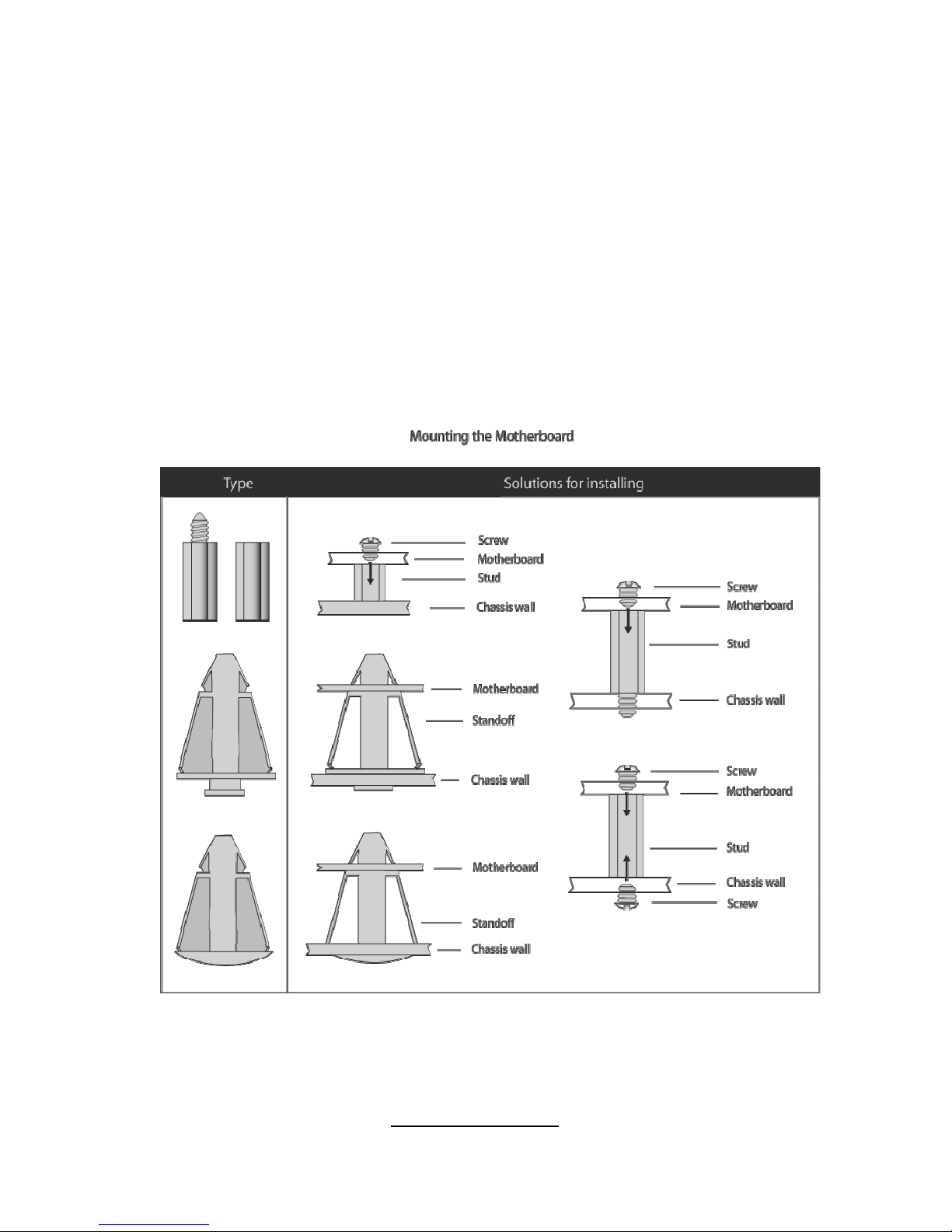
2.4 - Tips on Installing Motherboard in Chassis
Before installing your motherboard, make sure your chass is has the
necessary motherboard support studs installed. These studs are usually
metal and are gold in color. Usually, the chassis manufacturer will pre-install
the support studs. If you are unsure of stud placement, simply lay the
motherboard inside the chassis and align the screw holes of the
motherboard to the studs inside the case. If there are any studs missing,
you will know right away since the motherboard will not be able to be
securely installed.
Some chassis’ include plastic studs instead of metal. Although the plastic
studs are usable, TYAN recommends using metal studs with screws that will
fasten the motherboard more securely in place.
Below is a chart detailing what the most common motherboard studs look
like and how they should be installed.
20
http://www.tyan.com
2.5 - Installing the Processor & Cooling Fan
Your Tomcat i7230W S5162 supports the latest processor technologies from
Intel. Check the TYAN website for latest processor support:
http://www.tyan.com
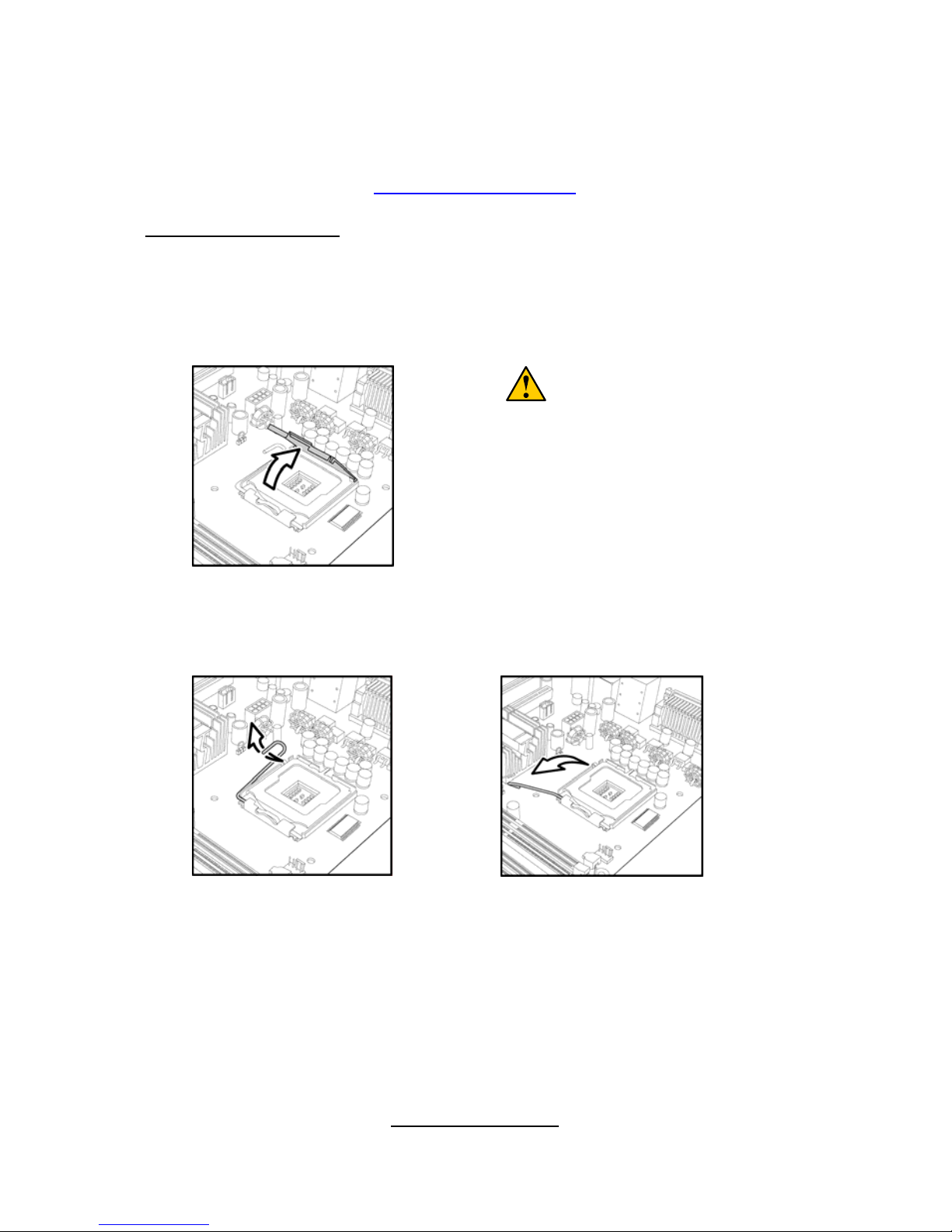
Processor Installation
The processor should be installed carefully. Make sure you are wearing an
antistatic strap and handle the processor as little as possible.
Follow these instructions to install your processor
1. Locate the processor socket on the motherboard and lift the protective
cover off as shown.
WARNING:
This new processor socket
designed by Intel is easy to be
damaged. The processor has to be
installed very carefully to prevent
the contact pins of the socket from
breaking. It is strongly
recommended the processor
installation job to be handled by the
experienced technician.
2. Pull the locking lever out of it’s locked position and let it spring into the
open position.
21
http://www.tyan.com
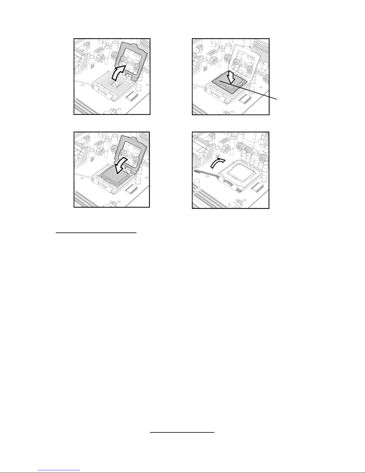
3. Lift the metal cover to expose the socket interior and place the socket in
as shown.
4. Close the cover and return the locking lever to its locked position.
Cooling Fan Installation
After you have installed the processor, the heatsink should be installed to
ensure that the processor runs efficiently and does not overheat. Use the
heatsink supplied for best results.
Follow these instructions to install the heatsink shown.
1. Apply some thermal compound (also called heatsink compound or
thermal grease) to the top of the processor. Try and apply a thin, even
layer over the top of the processor.
2. Align the heatsink with the four holes around the processor socket.
3. Press the heat sink down until the four screws are securely seated in the
holes.
4. Use screw drive to secure the four screws.
22
http://www.tyan.com
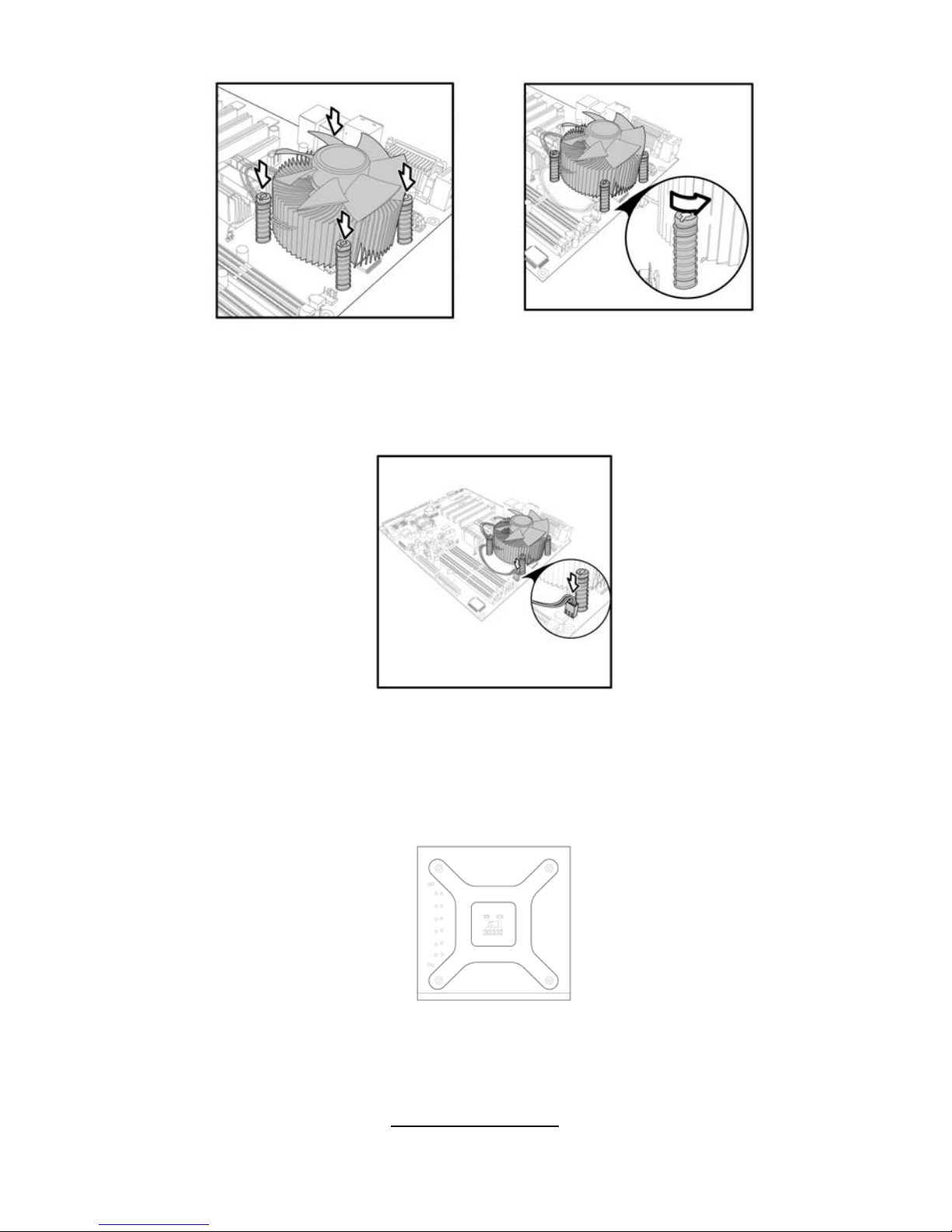
To remove the heatsink you will need to twist each of the black locking pe gs
until they spring up and unlock the heatsink from the motherboard.
Remember to connect the power supply for the fan to complete the installation.
Some heat sinks require a bracket to be installed beneath the motherboard
before the heat sink is placed on the top side of the motherboard. To install a
heat sink like this:
1 Turn the motherboard upside down and p lace the rear bracket in position
with the mounting posts poking through the corresponding holes in the
motherboard.
2 Turn the motherboard the right way up, holding the bracket in place.
3 Place the heat sink assembly on top of the processor.
It should match up with the mounting holes on the rear bracket.
23
http://www.tyan.com
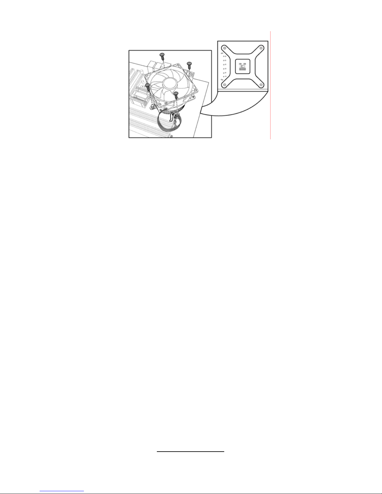
4 Screw the heat sink assembly into place.
If there is a fan on the heat sink you will need to connect the power lead for the fan
to one of the fan power supply pin headers on the motherboard.
24
http://www.tyan.com
2.6 - Installing the Memory
Before installing memory, ensure that the memory you have is compatible
with the motherboard and processor. Only DDR2-667/533/400 DIMM
modules are required. Check the TYAN Web site at: www.tyan.com for
details of the type of memory recommended for your motherboard.
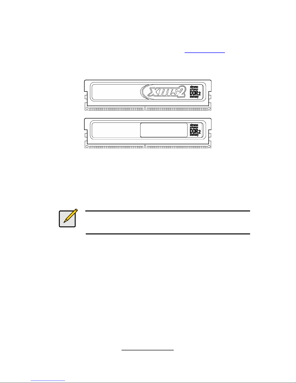
The following diagram shows common types of DDR2 memory modules.
Key points to note before installing memory:
• Only DDR2 667/533/400 unbuffered(Non-Reg)/ECC memory modules
are supported.
• All installed memory will automatically be detected and no j umpers or
settings need changing.
• The Tomcat i7230W S5162 supports up to 8GB of memory.
Notes
Standard DDR memory modules are not supported.
Registered Memory Module is NOT supported.
25
http://www.tyan.com
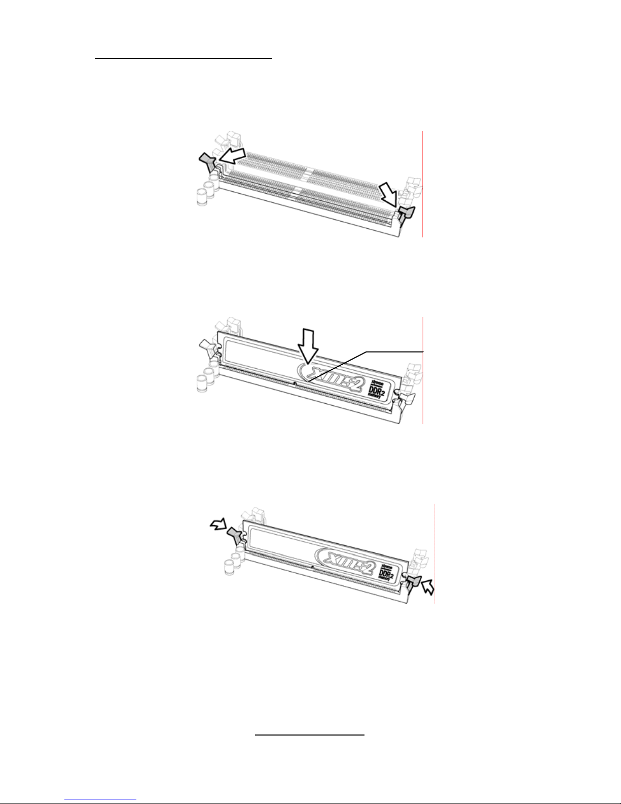
Memory Installation Procedure
Follow these instructions to install memory modules into the Tomcat i7230W
S5162.
1. Press the locking levers in the direction shown in the following illustration.
2. Align the memory module with the socket. The memory module is keyed
to fit only one way in the socket.
Key slot
3. Seat the module firmly into the socket by gently pressing down until it sits
flush with the socket. The locking levers pop up into place.
26
http://www.tyan.com
 Loading...