

TYAN Tomcat i7221A S5151, S5151 User Manual

Tomcat i7221A S5151 User’
s Manual
i
http://www.tyan.com
Tomcat i7221A
///
S5151
Revision 1.0
Copyright © TYAN Computer Corporation, 2004-2005. All rights reserved. No part of this
manual may be reproduced or translated without prior written consent from TYAN Computer
Corp.
All registered and unregis tered trademarks and company names contained in this manual are
property of their respective owners including, but not limited to the following.
TYAN, Tomcat, i7221 and S5151 are trademarks of TYAN Computer Corporation.
Intel Prescott and combinations thereof are trademarks of Intel Corporation.
Promise is a trademark of Promise Technology, Inc.
Award, AwardBIOS are trademarks of Award Software Incorporated.
Microsoft and Windows are trademarks of Microsoft Corporation.
IBM, PC, AT and PS/2 are trademarks of IBM Corporation.
Winbond is a trademark of Winbond Electronics Corporation.
SMSC is a trademark of Standard Microsystems Corporation.
Broadcom is a trademark of Broadcom Corporation.
Portable Document Format (PDF) is a trademark of Adobe Corporation.
Information contained in this document is furnished by TYAN Computer Corporation and has
been reviewed for accuracy and reliability prior to printing. TYAN assumes no liability
whatsoever, and disclaims any express or implied warranty, relating to sale and/or use of
TYAN products including liability or warranties relating to fitness for a particular purpose or
merchantability. TYAN retains the right to make changes to product descriptions and/or
specifications at any time, without notice. In no event will TYAN be held liable for any direct or
indirect, incidental or consequential damage, loss of use, loss of data or other malady resulting
from errors or inaccuracies of information contained in this document.

Tomcat i7221A S5151
Table of Contents
ii
http://www.tyan.com
Table of Contents
Before you begin….................................................................................................................v
Chapter 1: Introduction..........................................................................................................1
1.1 Congratulations!...........................................................................................................1
1.2 Hardware Specifications..............................................................................................1
Chapter 2: Board Installation.................................................................................................1
2.1 Installing the Motherboard............................................................................................1
2.1.1 Installation Notes ...............................................................................................1
2.2 Board Image ................................................................................................................2
2.3 Block Diagram..............................................................................................................3
2.4 Motherboard Components ...........................................................................................4
2.5 Jumpers and Connectors.............................................................................................5
2.5.1 Com Port: J5......................................................................................................6
2.5.2 SO-DIMM Socket: J12.......................................................................................6
2.5.3 Serial ATA RAID Connectors: J20/J21/J22/J23 (SATA1 / SATA 2 / SATA3 /
SATA4).......................................................................................................................7
2.5.4 LAN1/LAN2/LAN3 Disabled Headers: JP2/JP1/JP3..........................................7
2.5.5 Front Panel LAN1/LAN2 Link and Active LED Connectors: JP5/JP6.................8
2.5.6 Front Panel LAN1/LAN2 Speed LED Pin-Headers: JP4/JP7 .............................8
2.5.7 Front Fan Connectors: JP17/JP18/JP23............................................................9
2.5.8 Chassis Fan Connector: JP8.............................................................................9
2.5.9 CPU Fan Connector: JP22 ..............................................................................10
2.5.10 Front Panel USB 2.0 Connectors: JP12/JP13 ...............................................10
2.5.11 Clear CMOS Jumper: JP15 ...........................................................................11
2.5.12 Front Panel System Connector: JP16............................................................11
2.5.13 SMDC Connector: JP20 ................................................................................12
2.5.14 PCI-X Speed Select Header: JP14................................................................12
2.5.15 SMDC/ASF2.0 Select Headers:JP24/JP25....................................................13
2.6 Mounting the Motherboard.........................................................................................14
2.7 Installing Memory.......................................................................................................15
2.7.1 Memory Installation Procedure........................................................................16
2.8 Installing the Processor and Cooling Fan...................................................................17
2.9 Installing Drive Cables ...............................................................................................20
2.10 Installing Expansion Cards.......................................................................................21
2.11 Connecting External Devices...................................................................................21
2.11.1 Onboard LAN LED Color Definition ...............................................................22
2.12 Installing the Power Supply......................................................................................22
2.13 Finishing Up .............................................................................................................23
Chapter 3: BIOS Setup............................................................................................................1
3.1 About the BIOS............................................................................................................1
3.1.1 Starting Setup....................................................................................................1
3.1.2 Setup Basics......................................................................................................1
3.1.3 Getting Help.......................................................................................................1
3.1.4 In Case of Problems .......................................................................................... 2
3.1.5 Setup Variations................................................................................................2
3.2 Main BIOS Setup .........................................................................................................2
3.3 Standard CMOS Features............................................................................................4
3.4 Advanced BIOS Features............................................................................................5
3.4.1 CPU Features .................................................................................................... 7
3.4.2 Boot Sequence................................................................................................10
3.4.3 Console Redirection........................................................................................12
3.5 Advanced Chipsets Features.....................................................................................12
3.5.1 PCI Express Root Port Function......................................................................14

Tomcat i7221A S5151
Table of Contents
iii
http://www.tyan.com
3.6 Integrated Peripherals................................................................................................16
3.6.1 OnChip IDE Device..........................................................................................16
3.6.2 Onboard Device...............................................................................................18
3.6.3 Super IO Device..............................................................................................20
3.7 Power Management Setup.........................................................................................22
3.7.2 Power On Setup..............................................................................................24
3.7.3 Reload Global Timer Events ............................................................................ 25
3.8 PnP/PCI Configurations.............................................................................................26
3.8.1 IRQ Resources................................................................................................27
3.9 PC Health Status .......................................................................................................28
3.10 Frequency/Voltage Control......................................................................................28
3.11 Load Fail-Safe Defaults............................................................................................30
3.12 Load Optimized Defaults..........................................................................................30
3.13 Supervisor/User Password Setting...........................................................................31
3.14 Save & Exit Setup....................................................................................................32
3.15 Exit Without Saving..................................................................................................32
Chapter 4: SATA/RAID Setup (for SATA RAID model).........................................................1
4.1 Configuring BIOS for Intel RAID for Serial ATA on board.............................................1
4.1.1 Creating, Deleting, and Resetting RAID Sets .................................................... 1
4.1.2 Create RAID 0 or RAID 1 Volume......................................................................1
4.1.3 Delete RAID Volume..........................................................................................2
4.1.4 Reset RAID Data...............................................................................................2
4.2 Loading the Intel Application Accelerator RAID Edition Driver During Operating
System Install.....................................................................................................................2
4.2.1 Instructions on Creating F6 Floppy Diskette......................................................2
4.2.2 Installation Using F6 Method .............................................................................3
4.3 Intel RAID Option ROM................................................................................................4
4.3.1 Description.........................................................................................................4
4.3.2 Confirming Version of Intel RAID Option ROM Installed....................................4
4.3.3 Using the Intel RAID Option ROM.....................................................................4
4.4 Installing the Intel Application Accelerator RAID Edition ............................................10
4.4.1 Installation Caution..........................................................................................10
4.4.2 Steps to Take Before Installing the Intel Application Accelerator RAID Edition 10
4.4.3 Obtaining and Installing the Intel Application Accelerator RAID Edition...........10
4.5 Confirming the Intel Application Accelerator RAID Edition is Installed .......................14
4.6 Confirming Version of Intel Application Accelerator RAID Edition Installed ................ 14
4.6.1 Using the Intel Application Accelerator RAID Edition Utility:............................15
4.6.2 RAID Driver File Properties:.............................................................................15
4.7 Issues During Installation...........................................................................................15
4.7.1 Symptom: Incompatible Hardware...................................................................15
4.7.2 Symptom: Unable to launch Intel(R ) Application Accelerator Readme file......15
4.8 “RAID Ready”.............................................................................................................16
4.8.1 “RAID Ready” Definition ..................................................................................16
4.8.2 “RAID Ready” System Requirements ..............................................................16
4.8.3 Steps on Setting Up a “RAID Ready” System..................................................16
4.8.4 Converting a “RAID Ready” System into RAID 0 or RAID 1 System with
Migration Feature .....................................................................................................16
4.9 RAID Migration Instructions.......................................................................................17
4.9.1 Create RAID Volume from Existing Hard Drive................................................18
4.9.2 Migration Process May Take Considerable Time to Complete ........................21
4.10 Uninstalling the Intel Application Accelerator RAID Edition......................................22
4.10.1 Uninstall Warning...........................................................................................22
4.10.2 Windows* 2003 / Windows 2000...................................................................22
4.11 Unattended Installation Under Windows* 2003 / Windows 2000..............................23

Tomcat i7221A S5151
Table of Contents
iv
http://www.tyan.com
4.12 Intel Storage Utility...................................................................................................23
4.12.1 Description.....................................................................................................23
4.12.2 Create Volume Manually................................................................................23
4.12.3 Successful Creation.......................................................................................27
4.13 Configure BIOS for Adaptec RAID for Serial ATA on Board.....................................28
4.13.1 BIOS Configuration........................................................................................28
4.13.2 Installing Serial ATA (SATA) hard disks.........................................................28
4.13.3 Adaptec RAID Configuration Utility ................................................................28
4.13.4 Manage Array................................................................................................29
4.13.5 Create Array ..................................................................................................30
4.13. 6 Add/Delete Hotspare....................................................................................32
4.13.7 Initialize Drives...............................................................................................32
4.13.8 Disk Utilities ...................................................................................................33
Chapter 5: Diagnostics...........................................................................................................1
5.1 Beep Codes.................................................................................................................1
5.2 Flash Utility ..................................................................................................................1
Appendix I: Glossary..............................................................................................................1
Appendix II: Post Error Code for BIOS..................................................................................7
Technical Support.................................................................................................................12

Tomcat i7221A S5151 Before you begin…
v
http://www.tyan.com
Before you begin…
Check the package contents before you proceed.
The retail motherboard package should contain the following:
1 x Tomcat i7221A S5151 motherboard
1 x 34-Pin floppy drive cable
1 x Ultra-DMA-133/100/66/33 IDE cable
1 x Tomcat i7221A S5151User’s Manual
1 x Tomcat i7221A S5151 Quick Reference Guide
1 x TYAN driver CD
1 x Intel 82801FR (ICH6R) Driver Diskette
1 x Adaptec Driver Diskette
1 x I/O shield
2 x Serial ATA power cable
4 x Serial ATA cable
1 x USB2.0 cable
If any of these items are missing, please contact your vendor or dealer for replacement before
continuing with the installation process.

Tomcat i7221A S5151
Chapter 1: Introduction
1-1
http://www.tyan.com
Chapter 1: Introduction
1.1 Congratulations!
Congratulations on your purchase of the TYAN Tomcat i7221A S5151, one of the most
powerful and versatile motherboard solutions available for Intel Prescott and Tejas processors.
Based on the Intel E7221 MCH chipset, the S5151 offers exceptional performance and
outstanding features. With the x1 PCI Express slots, onboard two Gigabit Ethernet ports,
Serial ATA RAID, four Dual-channel DDR DIMM sockets and four optional SCSI ports, the
Tomcat i7221A S5151 is ideal to fit your server/workstation needs.
For more information about this and other TYAN products, visit the TYAN Web site at
http://www.tyan.com. Product FAQs, a list of distributors and advanced BIOS information are
also available on the Web site.
1.2 Hardware Specifications
Processors
Ÿ Single Socket-T (LGA775 socket)
Ÿ Intel “P rescott” processor with EM64T
support
Ÿ 800/533MHz FSB support
Expansion Slots
Ÿ One PCI-X 64-bit 133/100/66MHz bus
supports with
? One PCI-X slot
? One proprietary 200-pin SO-DIMM
connector
Ÿ Two x1 PCI Express connectors
Ÿ One 32/33 PCI v2.3 slots
Chipset
Ÿ Intel E7221 GMCH
Ÿ Intel ICH6R South Bridge
Ÿ Intel PXH-V I/O bridge
Ÿ SMSC DME1737 Super I/O
System Management
Ÿ SMSC DME1737 w/ hardware monitoring
Ÿ One 3+1-pin CPU Fan header w/
tachometer input and temperature-sensing
auto fan control
Ÿ Four 3-pin system Fan headers (two w/
tachometer input and temperature-sensing
auto fan control)
Ÿ Temperature and voltage monitoring
Ÿ Watchdog timer
Ÿ Port 80 code display LED
Memory
Ÿ Dual memory channels
Ÿ Supports Up to 4 DDR-333/400 DIMM
Ÿ Up to 4GB unbuffered, ECC/Non-ECC
memory
Integrated I/O Interfaces
Ÿ One floppy connector
Ÿ Four USB 2.0 ports (via cable)
Ÿ One COM2 port (via cable)
Ÿ One LPT port (via cable)
Ÿ Power/IDE/SATA LED connectors
Ÿ Two 2+2-pin headers for front panel
LAN LED
Ÿ TYAN 2 x 9 front-panel pin headers
Integrated LAN Controllers
Ÿ Two GbE LAN controllers
? Two Broadcom BCM5721 PCI
Express GbE LAN controller
? Operating at x1 PCI-E interface
? ASF 2.0 support
Ÿ One 10/100 Ethernet LAN controller
? Intel 82551
Optional modules
Ÿ M7901, SO-DIMM Ultra 320 SCSI card
? Adaptec AIC-7901X single-channel
Ultra 320 SCSI controller
? Adaptec HostRAID support w/RAID
0, 1, 10 supported
Ÿ M7902, SO-DIMM Ultra 320 SCSI card
? Adaptec AIC-7902W dual-channel
Ultra 320 SCSI controller
? Adaptec HostRAID support w/RAID
0, 1, 10 supported
Ÿ M8110 SO-DIMM SATA card
? Adaptec AIC-8110 SATA I controller
? Support up to 4-port (M8110) SATA
port running at 1.5GB/s
? Adaptec HostRAID support with
RAID 0, 1, 10 supported

Tomcat i7221A S5151
Chapter 1: Introduction
1-2
http://www.tyan.com
Integrated PCI IDE (ICH6R)
Ÿ Single channel master mode supports two
IDE devices
Ÿ Support for ATA-100/66/33 IDE drives and
ATAPI compliant devices
Integrated Serial ATA (ICH 6R)
Ÿ Four Serial ATA Host controllers embedded
Ÿ Support four Serial ports running at 1.5Gb/s
Ÿ RAID 0, 1 support
Integrated PCI Graphics
Ÿ 8-bit VGA DAC embedded the MCH to
support an analog display
Rear Panel I/O ports
Ÿ Stacked PS/2 Mouse & Keyboard ports
Ÿ One 15-pin VGA port
Ÿ One 9-pin COM port
Ÿ Two RJ45 10/100/1000 Base-T port w/
activity LED
Ÿ One RJ45 10/100 Base-T port w/activity
LED, 2x USB2.0 combo ports
BIOS
Ÿ Award BIOS 8Mbit Flash ROM
Ÿ Support APM 1.2 & ACPI 1.0
Ÿ PnP, DNI 2.0, WfM 2.0 Power
Management
Power
Ÿ EPS12V support, on board 4-phase
VRM
Ÿ Universal 24-pin + 8-pin power
connectors
Ÿ 4-pin auxiliary power connector
Form Factor
Ÿ ATX footprint
Ÿ 9.6” x 12.0” (243.8mm x 304.8mm)
Regulatory
Ÿ FCC Class B (Declaration of
Conformity)
Ÿ CE (Declaration of Conformity)
Ÿ BSMI
Note
TYAN reserves the right to add support or discontinue support for any OS
with or without notice.
Tomcat i7221A S5151 Chapter 2: Board Installation
2-1
http://www.tyan.com
Chapter 2: Board Installation
2.1 Installing the Motherboard
The Tomcat i7221A S5151 motherboard conforms fully to the ATX specification. Before
continuing with the installation, confirm that your chassis supports a standard ATX
motherboard. If you are unsure, contact your dealer for more information.
2.1.1 Installation Notes
This user manual contains important information and you should read it thoroughly before
attempting the installation procedure.
Precautions:
• Static electricity can damage components on your motherboard. Before touching the
product, discharge any static build up in yourself by touching a well grounded object
such as a metal water pipe or a grounded electrical appliance. TYAN recommends
putting on a good quality grounded wrist strap before removing your motherboard from
the antistatic bag.
• Disconnect your computer from the power supply before any disassembly procedure is
attempted.
• Touch the motherboard as little as possible and do not touch the bottom of the board at
• all. Bending or flexing the motherboard may break delicate components or copper tracks
on the board.
• Avoid touching any of the motherboard components.
• Place the motherboard on a grounded antistatic surface or on the antistatic bag in which
the board was shipped.
• Inspect the board for damage.
Read the following sections for detailed instructions on how to install your motherboard in a
chassis and add a processor, memory, and disk drives.
Warning
Do not apply power to the board if it appears damaged.
Tomcat i7221A S5151 Chapter 2: Board Installation
2-2
http://www.tyan.com
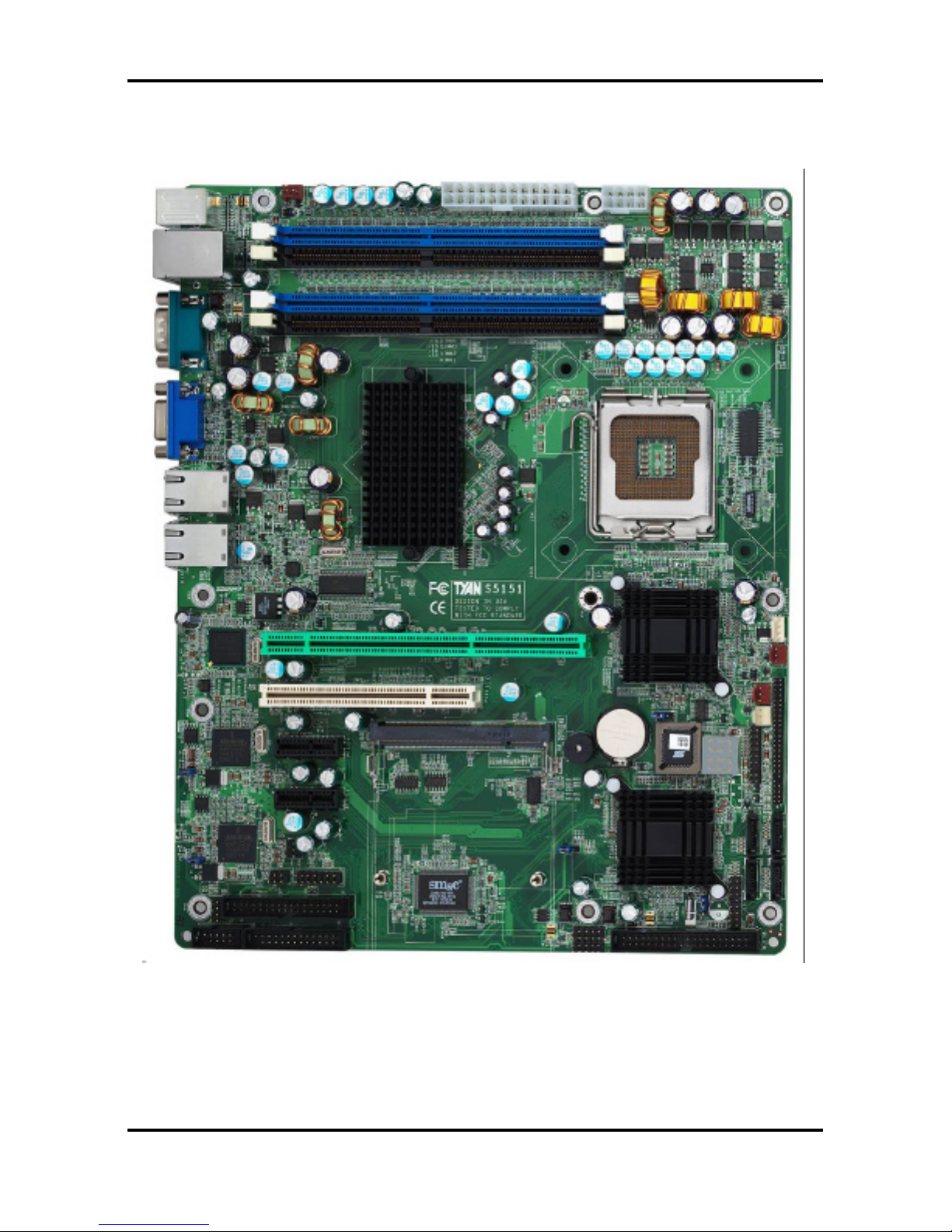
2.2 Board Image
The following is an image of the Tomcat i7221A S5151.
The above photograph is purely representative. Due to engineering updates and new
board revisions, certain components may change and or be repositioned. The picture
above may or may not look exactly like the board you received.

Tomcat i7221A S5151 Chapter 2: Board Installation
2-3
http://www.tyan.com
2.3 Block Diagram
The following is a block diagram of the Tomcat i7221A S5151.
Tomcat i7221A S5151 Chapter 2: Board Installation
2-4
http://www.tyan.com
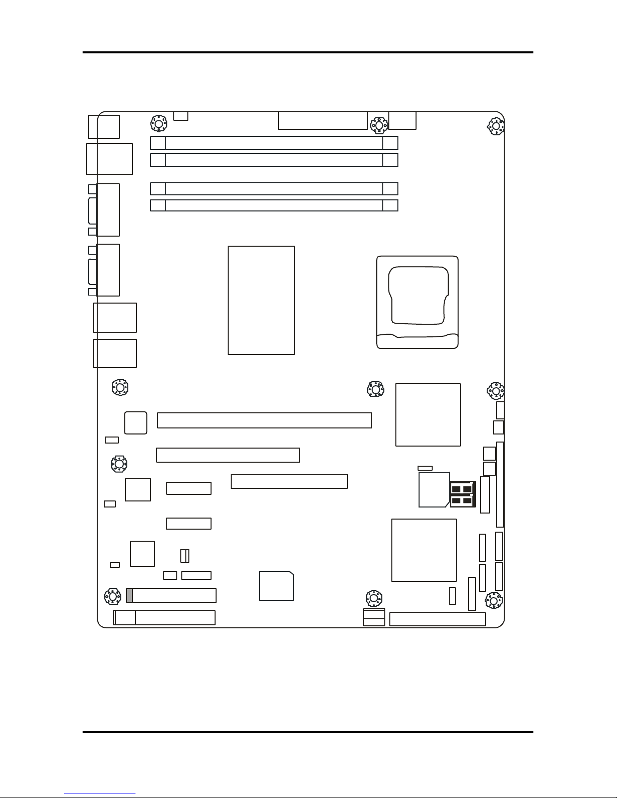
2.4 Motherboard Components
The diagram below shows the main motherboard components.
DIMM 2
DIMM 1
DIMM 4
DIMM 3
64-bit 133/100/66MHz PCI-X
X1 PCI Express
32-bit 33MHz (5V) PCI
IDE J17
X1 PCI Express
SO-DIMM
J25P
JP24
JP26
FDD
LPT
JP4/JP5/JP6/JP7
JP2
SMSC
I/O
JP1
LAN
82551
JP13
JP12
INTEL
ICH6R
JP15
SATA1
SATA3
JP9
SATA4
SATA2
SMDC
JP16
JP18
JP17
BIOS
JP23
JP22
INTEL
PXH-V
INTEL
E7221
Broadcom
5721
LAN
LAN
VGA
JP3
COM
PORT
USBX2
LAN
PS/2
JP14
JP8
Broadcom
5721
1
1
1
1
1
1
1
1
1
1
1 1
This diagram represents the latest version of the motherboard available at the time of
publishing. The board you receive may or may not look exactly like the above diagram.
Parts are not drawn to scale.
Tomcat i7221A S5151 Chapter 2: Board Installation
2-5
http://www.tyan.com
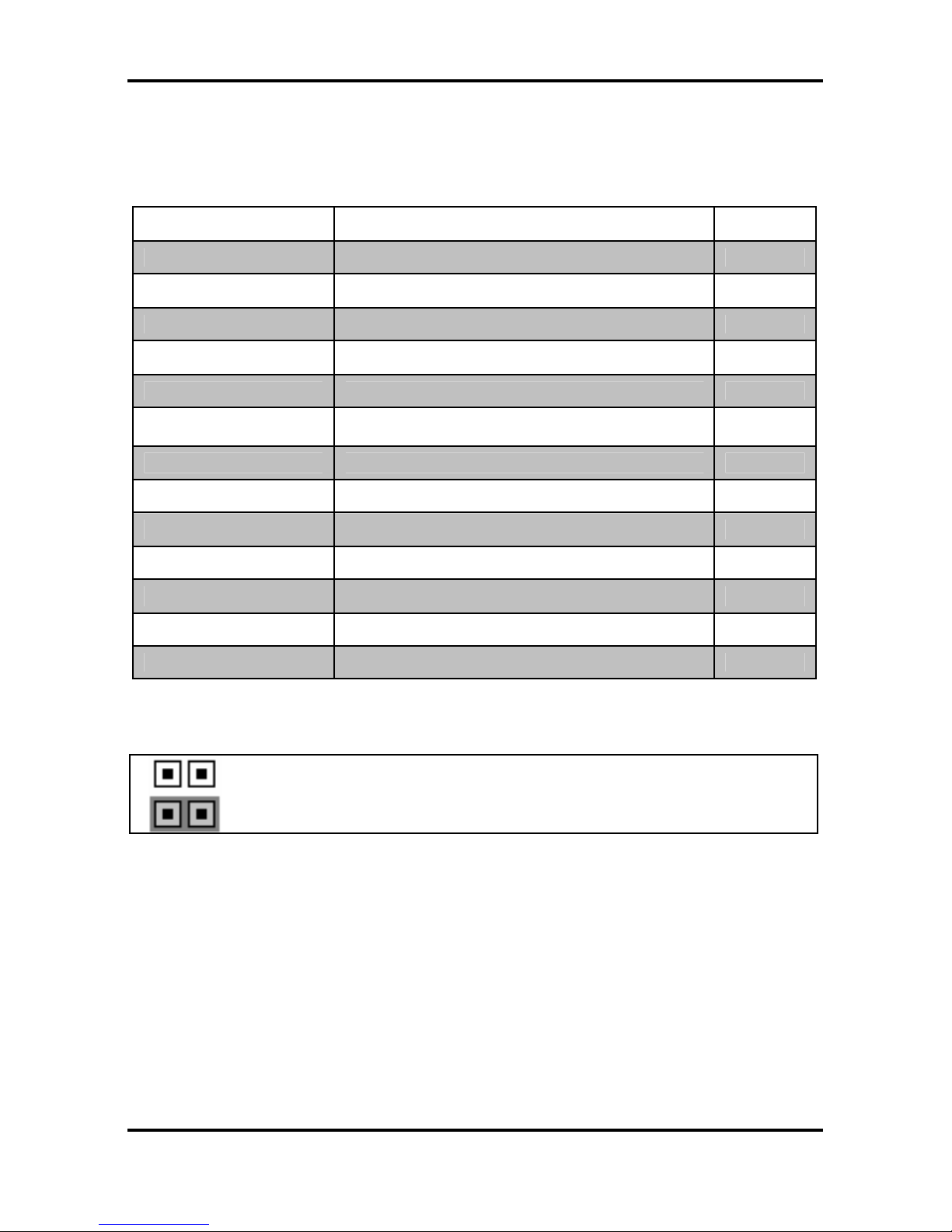
2.5 Jumpers and Connectors
Jumpers and pin headers are provided on your motherboard for configuration and connection
to peripherals. The following section shows you how to set your jumpers and use your pin
headers.
Connector Function Ref. Page
J5 COM2 port Page 2-6
J12 SO-DIMM socket Page 2-6
J20/J21/J22/J23 Serial ATA RAID connectors Page 2-7
JP1/JP2/JP3 LAN2/LAN1/LAN3 disabled headers Page 2-7
JP4/JP7 Front Panel LAN1/LAN2 Speed LED pin-headers Page 2-8
JP5/JP6
Front Panel LAN1/LAN2 Link and Active LED
connectors
Page 2-8
JP8 Chassis Fan connector Page 2-9
JP20 SMDC connector Page 2-12
JP12/JP13 Front panel USB2.0 connectors Page 2-10
JP14 PCI-X speed select header Page 2-12
JP15 Clear CMOS jumper Page 2-11
JP17/JP18/JP23 Front fan connectors Page 2-9
JP24/JP25 SMDC/ASF2.0 select headers Page 2-13
* Some jumpers and headers are optional and not available with the board due to the different
configurations.
Jumper Legend
Jumper OFF – open (without jumper cap)
Jumper ON – closed (with jumper cap)
Tomcat i7221A S5151 Chapter 2: Board Installation
2-6
http://www.tyan.com
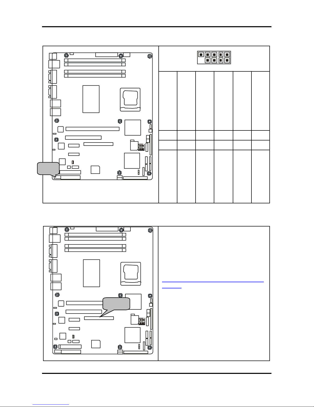
2.5.1 Com Port: J5
10 2
9 1
Signal Description
GND
(Ground)
DTR
(Data-Terminal-Ready)
TX
(Transfer-Data)
RX
(Receive-Data)
DCD
(Data Carrier Detect)
Pin#
9 7 6 3
1
Pin#
10 8 5 4
2
DIMM 2
DIMM 1
DIMM 4
DIMM 3
64bit 133/100/66MHz PCI-X
X1 PCI Express
32-bit 33MHz (5V) PCI
IDE J17
X1 PCI Express
SO-DIMM
J25P JP24
FDD
LPT
JP4/JP5/JP6/JP7
JP2
BROADCOM
5721
BROADCOM
5721
SMSC
I/O
JP1
LAN
82551
JP13
JP12
INTEL
ICH6R
JP15
SATA1
SATA3
J19
SATA4
SATA2
SMDC
JP16
JP18
JP17
BIOS
JP23
JP22
INTEL
PXH-V
INTEL
PXH-V
INTEL
E7221
BROADCOM
5721
JP3
LAN
LAN
VGA
JP3
COM
PORT
USBX2
LAN
PS/2
JP14
JP18
J5
Signal Description
NC/Key
RI
(Ring-Indicator)
CTS
(Clear-to-Send)
RTS
(Request-to- Send)
DSR
(Data-Set-Ready)
2.5.2 SO-DIMM Socket: J12
DIMM 2
DIMM 1
DIMM 4
DIMM 3
64bit 133/100/66MHz PCI-X
X1 PCI Express
32-bit 33MHz (5V) PCI
IDE J17
X1 PCI Express
SO-DIMM
J25P JP24
FDD
LPT
JP4/JP5/JP6/JP7
JP2
BROADCOM
5721
BROADCOM
5721
SMSC
I/O
JP1
LAN
82551
JP13
JP12
INTEL
ICH6R
JP15
SATA1
SATA3
J19
SATA4
SATA2
SMDC
JP16
JP18
JP17
BIOS
JP23
JP22
INTEL
PXH-V
INTEL
PXH-V
INTEL
E7221
BROADCOM
5721
JP3
LAN
LAN
VGA
JP3
COM
PORT
USBX2
LAN
PS/2
JP14
JP18
J5
Connect SCSI Daughter Card
Compatible with Tyan Taro M7902 or
M7901
Also connect SO-DIMM SATA card
Compatible with Tyan Taro M8110
http://www.tyan.com/products/html/access
ory.html
J5 J12
Tomcat i7221A S5151 Chapter 2: Board Installation
2-7
http://www.tyan.com
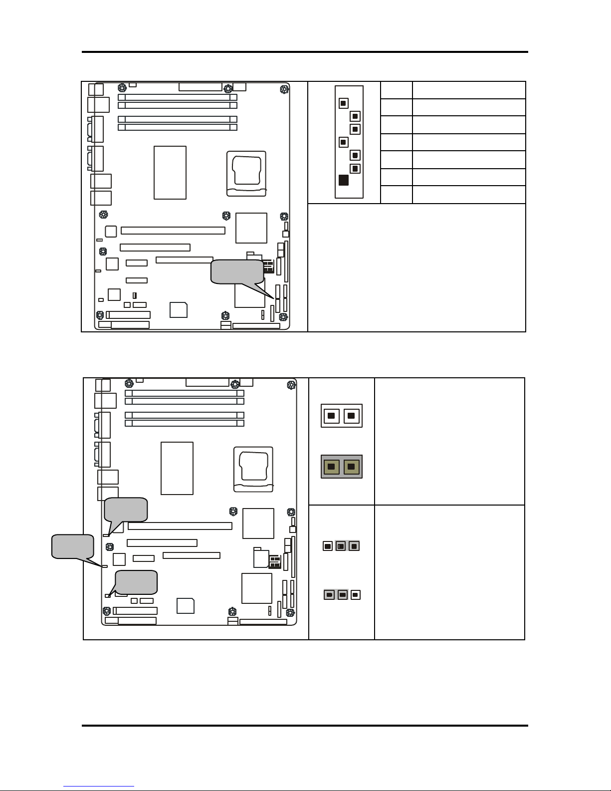
2.5.3 Serial ATA RAID Connectors: J20/J21/J22/J23 (SATA1 / SATA2 / SATA3 / SATA4)
7 GND
6 RXP
5 RXN
4 GND
3 TXN
2 TXP
7
1
1 GND
DIMM 2
DIMM 1
DIMM 4
DIMM 3
64bit 133/100/66MHz PCI-X
X1 PCI Express
32-bit 33MHz (5V) PCI
IDE J17
X1 PCI Express
SO-DIMM
J25P JP24
FDD
LPT
JP4/JP5/JP6/JP7
JP2
BROADCOM
5721
BROADCOM
5721
SMSC
I/O
JP1
LAN
82551
JP13
JP12
INTEL
ICH6R
JP15
SATA1
SATA3
J19
SATA4
SATA2
SMDC
JP16
JP18
JP17
BIOS
JP23
JP22
INTEL
PXH-V
INTEL
PXH-V
INTEL
E7221
BROADCOM
5721
JP3
LAN
LAN
VGA
JP3
COM
PORT
USBX2
LAN
PS/2
JP14
JP18
J5
Connects to the Serial ATA ready drives
via the Serial ATA cable
You may use any two of the four Serial
ATA ports to have the support of RAID 0
and 1 through the on board ICH6R south
bridge chip.
2.5.4 LAN1/LAN2/LAN3 Disabled Headers: JP2/JP1/JP3
1
1
JP1/JP2
OPEN: Disabled
CLOSED: Enabled (Default)
DIMM 2
DIMM 1
DIMM 4
DIMM 3
64bit 133/100/66MHz PCI-X
X1 PCI Express
32-bit 33MHz (5V) PCI
IDE J17
X1 PCI Express
SO-DIMM
J25P JP24
FDD
LPT
JP4/JP5/JP6/JP7
JP2
BROADCOM
5721
BROADCOM
5721
SMSC
I/O
JP1
LAN
82551
JP13
JP12
INTEL
ICH6R
JP15
SATA1
SATA3
J19
SATA4
SATA2
SMDC
JP16
JP18
JP17
BIOS
JP23
JP22
INTEL
PXH-V
INTEL
PXH-V
INTEL
E7221
BROADCOM
5721
JP3
LAN
LAN
VGA
JP3
COM
PORT
USBX2
LAN
PS/2
JP14
JP18
J5
1
3
3
1
JP3
Pin 1-2 Closed:
Enable
(Default)
Pin 2-3 Closed: Disable
SATA
JP3 JP1 JP2
Tomcat i7221A S5151 Chapter 2: Board Installation
2-8
http://www.tyan.com
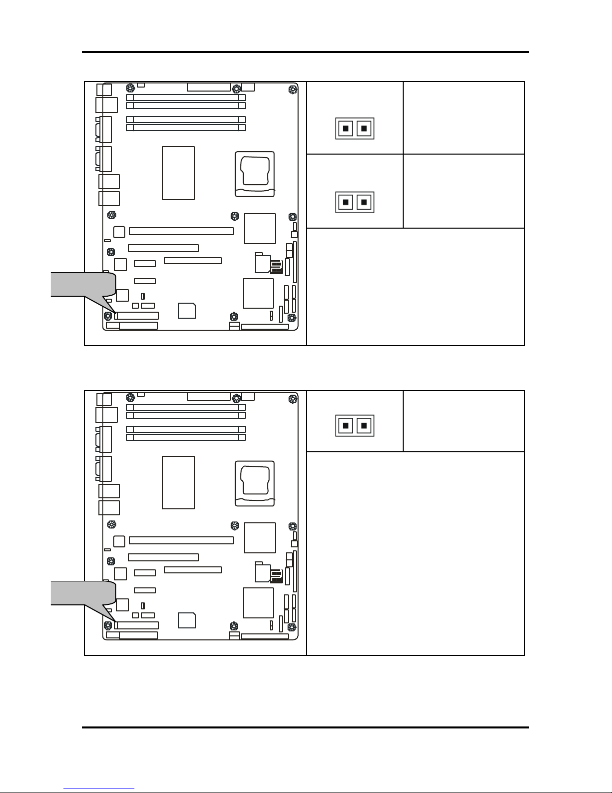
2.5.5 Front Panel LAN1/LAN2 Link and Active LED Connectors: JP5/JP6
JP5 (for LAN1)
1
Pin 1: LED+
Pin 2: LED-
JP6 (for LAN2)
1
Pin 1: LED+
Pin 2: LED-
DIMM 2
DIMM 1
DIMM 4
DIMM 3
64bit 133/100/66MHz PCI-X
X1 PCI Express
32-bit 33MHz (5V) PCI
IDE J17
X1 PCI Express
SO-DIMM
J25P JP24
FDD
LPT
JP4/JP5/JP6/JP7
JP2
BROADCOM
5721
BROADCOM
5721
SMSC
I/O
JP1
LAN
82551
JP13
JP12
INTEL
ICH6R
JP15
SATA1
SATA3
J19
SATA4
SATA2
SMDC
JP16
JP18
JP17
BIOS
JP23
JP22
INTEL
PXH-V
INTEL
PXH-V
INTEL
E7221
BROADCOM
5721
JP3
LAN
LAN
VGA
JP3
COM
PORT
USBX2
LAN
PS/2
JP14
JP18
J5
Use these headers to connect with the
front panel link/activity LEDs for LAN1 and
LAN2.
2.5.6 Front Panel LAN1/LAN2 Speed LED Pin-Headers: JP4/JP7
1
Pin 1: Green+
Pin 1: Orange+
DIMM 2
DIMM 1
DIMM 4
DIMM 3
64bit 133/100/66MHz PCI-X
X1 PCI Express
32-bit 33MHz (5V) PCI
IDE J17
X1 PCI Express
SO-DIMM
J25P JP24
FDD
LPT
JP4/JP5/JP6/JP7
JP2
BROADCOM
5721
BROADCOM
5721
SMSC
I/O
JP1
LAN
82551
JP13
JP12
INTEL
ICH6R
JP15
SATA1
SATA3
J19
SATA4
SATA2
SMDC
JP16
JP18
JP17
BIOS
JP23
JP22
INTEL
PXH-V
INTEL
PXH-V
INTEL
E7221
BROADCOM
5721
JP3
LAN
LAN
VGA
JP3
COM
PORT
USBX2
LAN
PS/2
JP14
JP18
J5
Use these headers to connect with the
front panel dual color LEDs to indicate the
speed of LAN1 and LAN2.
Off = 10 LAN
Green = 100 LAN
Orange = GbE LAN
Reference section 2.11.1 for the correct
LAN LED color definition.
JP4 for LAN1, JP7 for LAN2
JP5/JP6
JP4/JP7
Tomcat i7221A S5151 Chapter 2: Board Installation
2-9
http://www.tyan.com
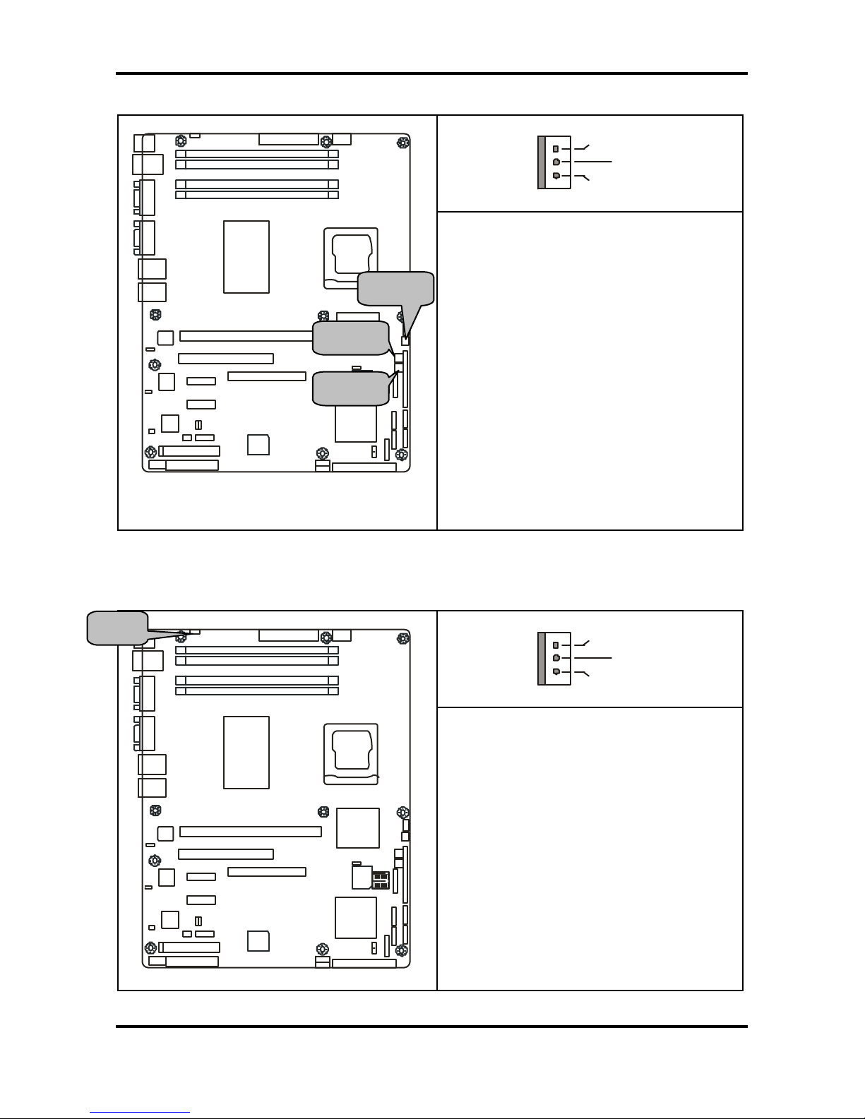
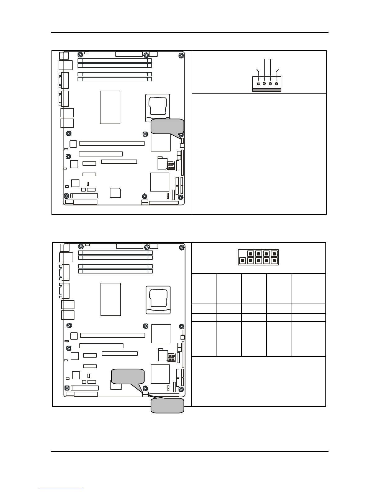
2.5.7 Front Fan Connectors: JP17/JP18/JP23
+12V
GND
NC
DIMM 2
DIMM 1
DIMM 4
DIMM 3
64bit 133/100/66MHz PCI-X
X1 PCI Express
32-bit 33MHz (5V) PCI
IDE J17
X1 PCI Express
SO-DIMM
J25P JP24
FDD
LPT
JP4/JP5/JP6/JP7
JP2
BROADCOM
5721
BROADCOM
5721
SMSC
I/O
JP1
LAN
82551
JP13
JP12
INTEL
ICH6R
JP15
SATA1
SATA3
J19
SATA4
SATA2
SMDC
JP16
JP18
JP17
BIOS
JP23
JP22
INTEL
PXH-V
INTEL
PXH-V
INTEL
E7221
BROADCOM
5721
JP3
LAN
LAN
VGA
JP3
COM
PORT
USBX2
LAN
PS/2
JP14
JP8
J5
Use these headers to connect the chassis
cooling fans to your motherboard to keep
the system stable and reliable.
JP17 and JP23 support the tachometer
monitoring and auto fan speed control.
2.5.8 Chassis Fan Connector: JP8
+12V
GND
NC
DIMM 2
DIMM 1
DIMM 4
DIMM 3
64bit 133/100/66MHz PCI-X
X1 PCI Express
32-bit 33MHz (5V) PCI
IDE J17
X1 PCI Express
SO-DIMM
J25P JP24
FDD
LPT
JP4/JP5/JP6/JP7
JP2
BROADCOM
5721
BROADCOM
5721
SMSC
I/O
JP1
LAN
82551
JP13
JP12
INTEL
ICH6R
JP15
SATA1
SATA3
J19
SATA4
SATA2
SMDC
JP16
JP18
JP17
BIOS
JP23
JP22
INTEL
PXH-V
INTEL
PXH-V
INTEL
E7221
BROADCOM
5721
JP3
LAN
LAN
VGA
JP3
COM
PORT
USBX2
LAN
PS/2
JP14
JP8
J5
Use this header to connect the chassis
cooling fan to your motherboard to keep
the system at optimum performance
levels.
These connectors support the tachometer
monitoring and auto fan speed control.
JP8 JP23
JP17
JP18
Tomcat i7221A S5151 Chapter 2: Board Installation
2-10
http://www.tyan.com
2.5.9 CPU Fan Connector: JP22
+12V
V3P3
Speed Control
Tachometer
DIMM 2
DIMM 1
DIMM 4
DIMM 3
64bit 133/100/66MHz PCI-X
X1 PCI Express
32-bit 33MHz (5V) PCI
IDE J17
X1 PCI Express
SO-DIMM
J25P JP24
FDD
LPT
JP4/JP5/JP6/JP7
JP2
BROADCOM
5721
BROADCOM
5721
SMSC
I/O
JP1
LAN
82551
JP13
JP12
INTEL
ICH6R
JP15
SATA1
SATA3
J19
SATA4
SATA2
SMDC
JP16
JP18
JP17
BIOS
JP23
JP22
INTEL
PXH-V
INTEL
PXH-V
INTEL
E7221
BROADCOM
5721
JP3
LAN
LAN
VGA
JP3
COM
PORT
USBX2
LAN
PS/2
JP14
JP18
J5
Use this header to connect the processor
cooling fan to your motherboard to keep
the system stable and reliable.
This connector supports the tachometer
monitoring and auto fan speed control.
2.5.10 Front Panel USB 2.0 Connectors: JP12/JP13
10 2
9 1
NC
GND
Data 1+
Data 1 -
+5V
9 7 5 3 1
10 8 6 4 2
GND
GND
Data 2+
Data 2 -
+5V
DIMM 2
DIMM 1
DIMM 4
DIMM 3
64bit 133/100/66MHz PCI-X
X1 PCI Express
32-bit 33MHz (5V) PCI
IDE J17
X1 PCI Express
SO-DIMM
J25P JP24
FDD
LPT
JP4/JP5/JP6/JP7
JP2
BROADCOM
5721
BROADCOM
5721
SMSC
I/O
JP1
LAN
82551
JP13
JP12
INTEL
ICH6R
JP15
SATA1
SATA3
J19
SATA4
SATA2
SMDC
JP16
JP18
JP17
BIOS
JP23
JP22
INTEL
PXH-V
INTEL
PXH-V
INTEL
E7221
BROADCOM
5721
JP3
LAN
LAN
VGA
JP3
COM
PORT
USBX2
LAN
PS/2
JP14
JP18
J5
Use these headers to Connect to the USB
devices via the enclosed USB cable.
JP22
JP13
JP12
Tomcat i7221A S5151 Chapter 2: Board Installation
2-11
http://www.tyan.com
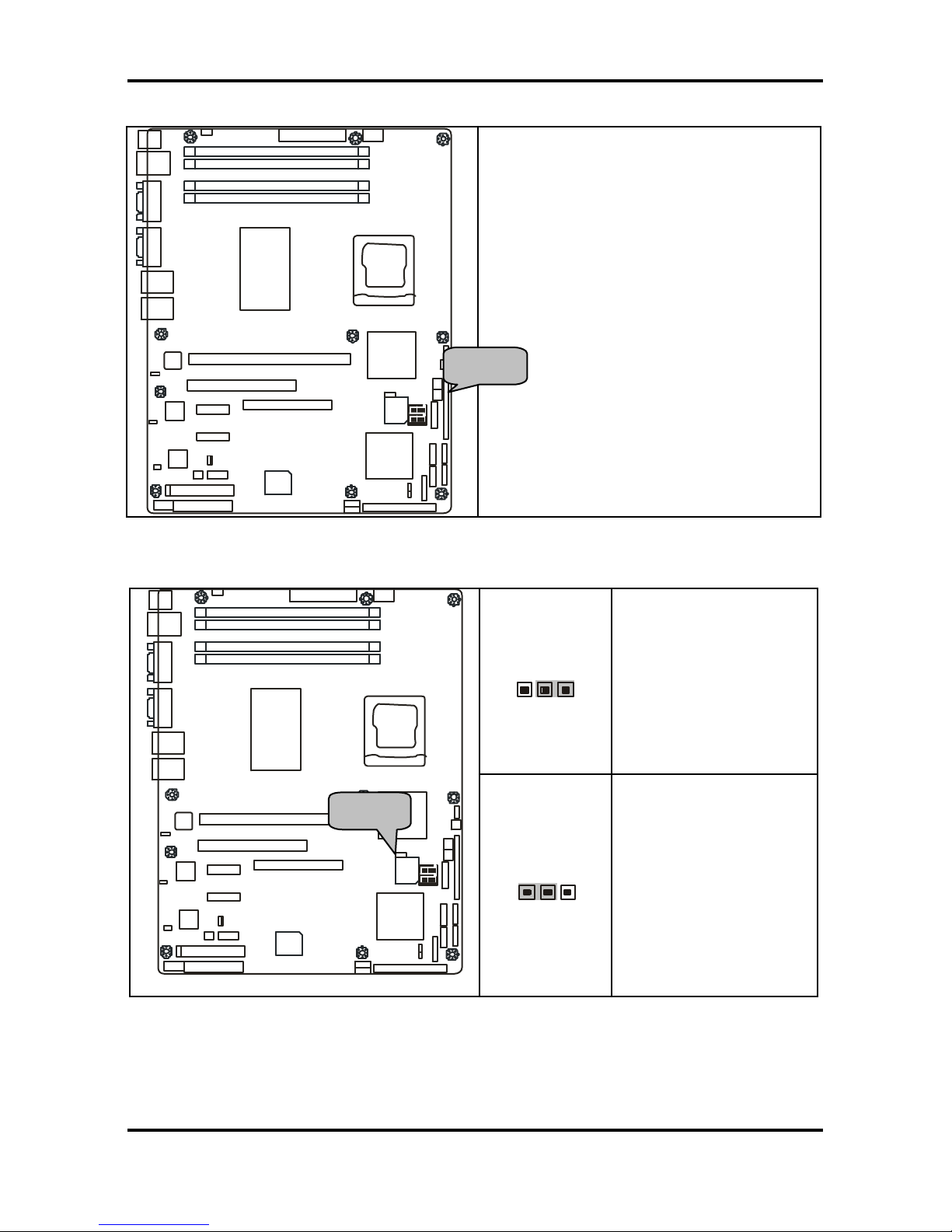
2.5.11 Clear CMOS Jumper: JP15
3
1
Default
3
1
Clear
DIMM 2
DIMM 1
DIMM 4
DIMM 3
64bit 133/100/66MHz PCI-X
X1 PCI Express
32-bit 33MHz (5V) PCI
IDE J17
X1 PCI Express
SO-DIMM
J25P JP24
FDD
LPT
JP4/JP5/JP6/JP7
JP2
BROADCOM
5721
BROADCOM
5721
SMSC
I/O
JP1
LAN
82551
JP13
JP12
INTEL
ICH6R
JP15
SATA1
SATA3
J19
SATA4
SATA2
SMDC
JP16
JP18
JP17
BIOS
JP23
JP22
INTEL
PXH-V
INTEL
PXH-V
INTEL
E7221
BROADCOM
5721
JP3
LAN
LAN
VGA
JP3
COM
PORT
USBX2
LAN
PS/2
JP14
JP18
J5
Use this jumper when you forgot your
system/setup password or need to clear
system BIOS setting.
How to clear the CMOS data
- P ower off system and disconnect
power supply from AC source
- Use jumper cap to close Pin_2 and 3
for several seconds to Clear CMOS
- Replace jumper cap to close Pin_1
and 2 (default setting)
- Reconnect power supply to AC
source
P ower on system
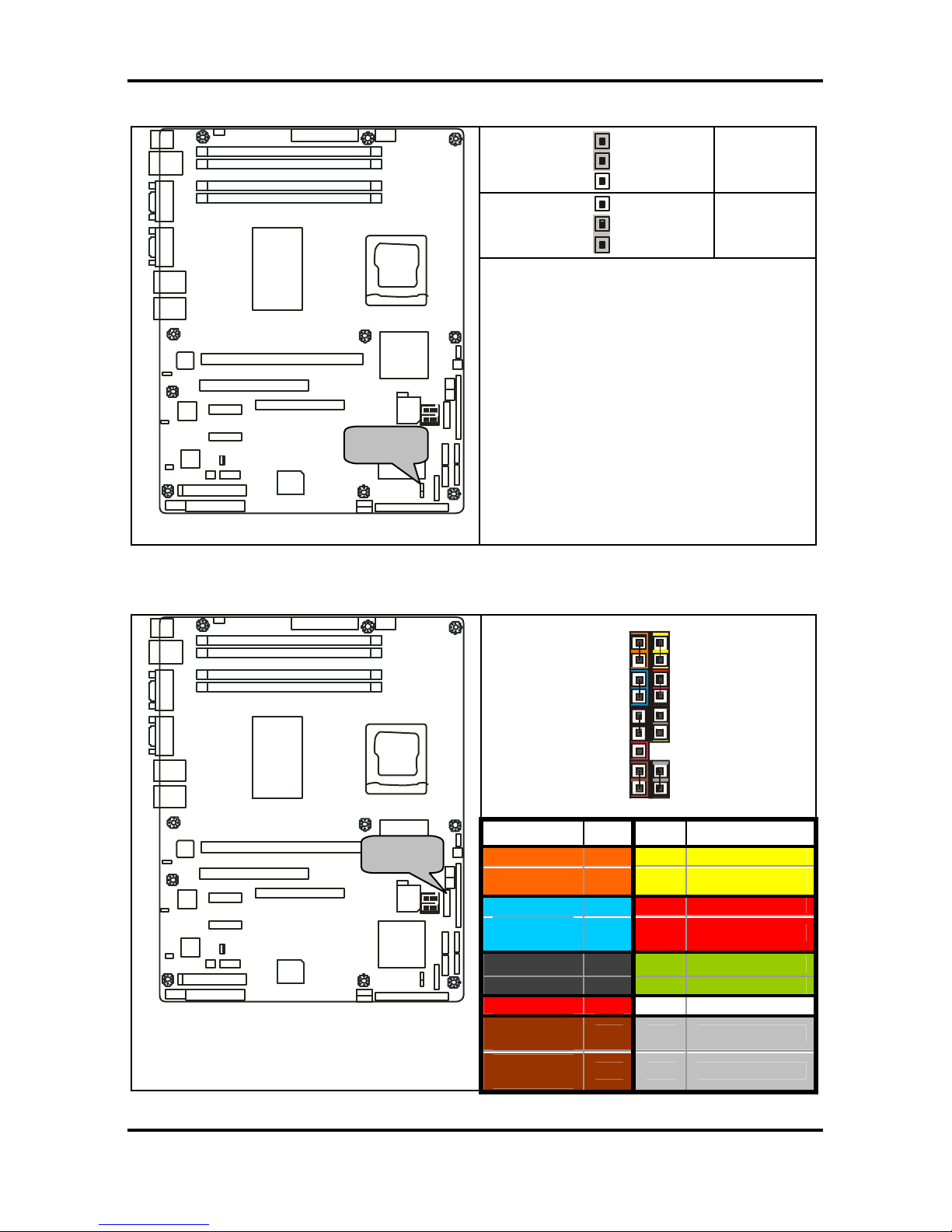
2.5.12 Front Panel System Connector: JP16
1 2
17 18
Function PIN PIN Function
HD_LED+
1 2
PLED+
HD_LED-
3 4
PLED-
GND
5 6
Power Button
Reset
Button
7 8
GND
EXINT +5V
9 10
NC
EXINT
11 12
GND
+5VSB
13 14
NC
SMBUS
Data
15 16
GND
DIMM 2
DIMM 1
DIMM 4
DIMM 3
64bit 133/100/66MHz PCI-X
X1 PCI Express
32-bit 33MHz (5V) PCI
IDE J17
X1 PCI Express
SO-DIMM
J25P JP24
FDD
LPT
JP4/JP5/JP6/JP7
JP2
BROADCOM
5721
BROADCOM
5721
SMSC
I/O
JP1
LAN
82551
JP13
JP12
INTEL
ICH6R
JP15
SATA1
SATA3
J19
SATA4
SATA2
SMDC
JP16
JP18
JP17
BIOS
JP23
JP22
INTEL
PXH-V
INTEL
PXH-V
INTEL
E7221
BROADCOM
5721
JP3
LAN
LAN
VGA
JP3
COM
PORT
USBX2
LAN
PS/2
JP14
JP18
J5
SMBUS
Clock
17 18
INTRU
JP15
JP16
Tomcat i7221A S5151 Chapter 2: Board Installation
2-12
http://www.tyan.com
2.5.13 SMDC Connector: JP20
DIMM 2
DIMM 1
DIMM 4
DIMM 3
64bit 133/100/66MHz PCI-X
X1 PCI Express
32-bit 33MHz (5V) PCI
IDE J17
X1 PCI Express
SO-DIMM
J25P JP24
FDD
LPT
JP4/JP5/JP6/JP7
JP2
BROADCOM
5721
BROADCOM
5721
SMSC
I/O
JP1
LAN
82551
JP13
JP12
INTEL
ICH6R
JP15
SATA1
SATA3
J19
SATA4
SATA2
SMDC
JP16
JP18
JP17
BIOS
JP23
JP22
INTEL
PXH-V
INTEL
PXH-V
INTEL
E7221
BROADCOM
5721
JP3
LAN
LAN
VGA
JP3
COM
PORT
USBX2
LAN
PS/2
JP14
JP18
J5
For connection with Tyan Server
Management Daughter Card (SMDC)
*Optional on some versions of the S5151
motherboard.
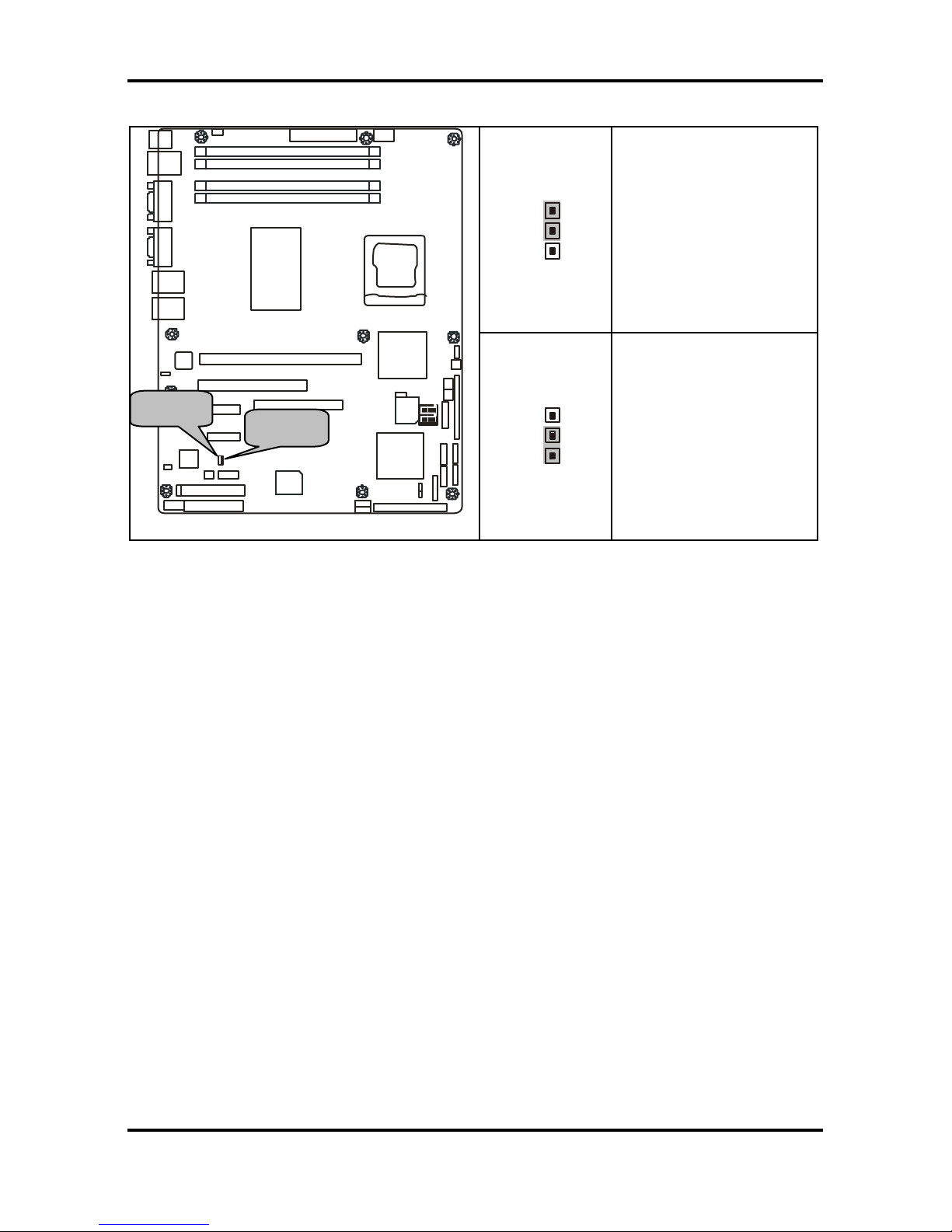
2.5.14 PCI-X Speed Select Header: JP14
1
3
Pin 1-2 Closed: 133MHz
(Default)
DIMM 2
DIMM 1
DIMM 4
DIMM 3
64bit 133/100/66MHz PCI-X
X1 PCI Express
32-bit 33MHz (5V) PCI
IDE J17
X1 PCI Express
SO-DIMM
J25P JP24
FDD
LPT
JP4/JP5/JP6/JP7
JP2
BROADCOM
5721
BROADCOM
5721
SMSC
I/O
JP1
LAN
82551
JP13
JP12
INTEL
ICH6R
JP15
SATA1
SATA3
J19
SATA4
SATA2
SMDC
JP16
JP18
JP17
BIOS
JP23
JP22
INTEL
PXH-V
INTEL
PXH-V
INTEL
E7221
BROADCOM
5721
JP3
LAN
LAN
VGA
JP3
COM
PORT
USBX2
LAN
PS/2
JP14
JP18
J5
3
1
Pin 2-3 Closed: 100MHz
JP20
JP14
Tomcat i7221A S5151 Chapter 2: Board Installation
2-13
http://www.tyan.com
2.5.15 SMDC/ASF2.0 Select Headers:JP24/JP25
3
1
Support ASF 2.0
DIMM 2
DIMM 1
DIMM 4
DIMM 3
64bit 133/100/66MHz PCI-X
X1 PCI Express
32-bit 33MHz (5V) PCI
IDE J17
X1 PCI Express
SO-DIMM
J25P JP24
FDD
LPT
JP4/JP5/JP6/JP7
JP2
BROADCOM
5721
BROADCOM
5721
SMSC
I/O
JP1
LAN
82551
JP13
JP12
INTEL
ICH6R
JP15
SATA1
SATA3
J19
SATA4
SATA2
SMDC
JP16
JP18
JP17
BIOS
JP23
JP22
INTEL
PXH-V
INTEL
PXH-V
INTEL
E7221
BROADCOM
5721
JP3
LAN
LAN
VGA
JP3
COM
PORT
USBX2
LAN
PS/2
JP14
JP18
J5
3
1
Support SMDC card
JP25
JP24
Tomcat i7221A S5151 Chapter 2: Board Installation
2-14
http://www.tyan.com
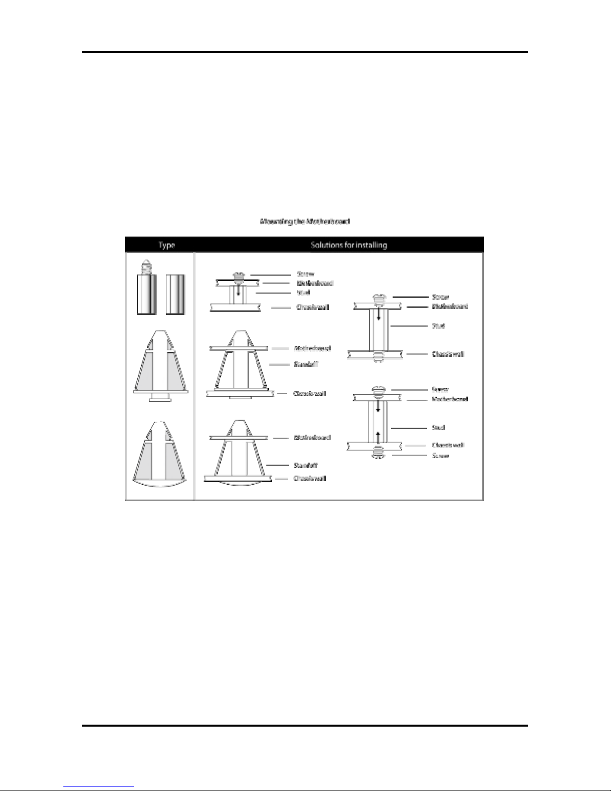
2.6 Mounting the Motherboard
Before installing your motherboard, ensure that your chassis is fully compatible. The Tomcat
i7221A S5151 motherboard conforms fully to the ATX specification. Your chassis should
include preinstalled mounting posts that match exactly with the mounting holes in the
motherboard. Lay the motherboard on top of the mounting holes to ensure that all the
necessary mounting posts exist in your chassis and that they match the mounting holes on
the motherboard.
Some chassis’ include plastic studs instead of metal. Although the plastic studs are usable,
TYAN recommends using metal studs with screws that will fasten the motherboard more
securely in place.
See the diagram below for some examples of typical motherboard fixing studs.
TIP: Use metal studs if possible, as they hold the motherboard into place more securely than
plastic standoffs.
Tomcat i7221A S5151 Chapter 2: Board Installation
2-15
http://www.tyan.com
2.7 Installing Memory
Before installing memory, ensure that the memory you have is compatible with the
motherboard and processor. PC2700/PC3200 (DDR333/DDR400) modules are required.
Check the TYAN Web site at: www.tyan.com for details of the type of memory recommended
for your motherboard.
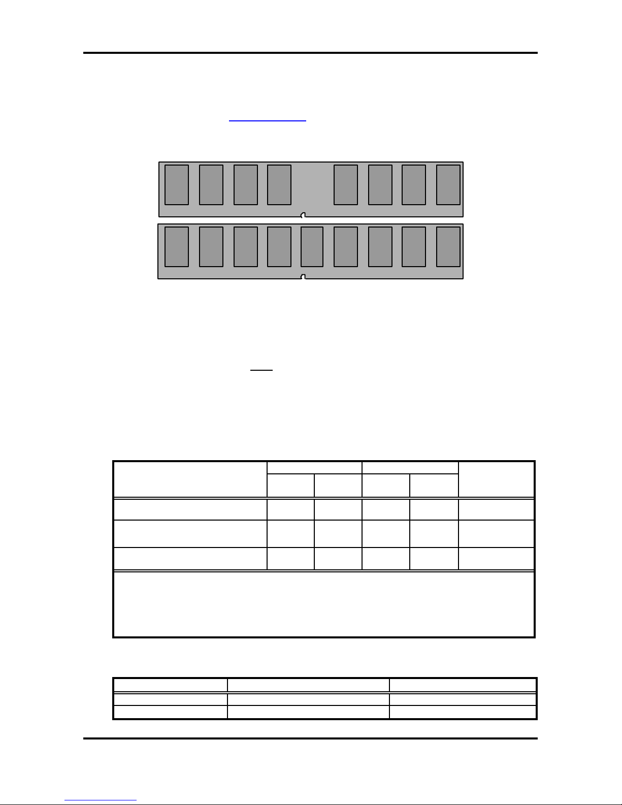
The following diagram shows common types of memory modules.
DDR Unbuffered ECC
DDR Unbuffered
Key points to note before installing memory:
• 128MB, 256MB, 512MB and 1GB Non-Reg/ECC or Non-Reg/Non- ECC
PC2700/PC3200 DDR memory modules are supported
• All installed memory will be automatically detected and no jumpers or settings need
to be set.
• The Tomcat i7221A S5151 supports up to 4GB of memory
• Registered Memory is NOT supported .
• You can install either single or double-sided modules on this motherboard. Each
DIMM can work in single-channel mode or dual-channel mode. Please note that
memory modules of the same type and density are required while using dualchannel DDR. Mismatched memory may cause system instability.
Refer to the following table for details of dual-channel DDR.
Channel A Channel B
Dual-Channel Mode
DIMM1
(Blue)
DIMM2
(Black)
DIMM3
(Blue)
DIMM4
(Black)
System
Density
Two DIMM Symmetrical
Population
ü ü 256MB~2GB
Two DIMM Symmetrical
Population
ü ü 256MB~2GB
Four DIMM Symmetrical
Population
ü ü ü ü 512MB~4GB
Note
1. ü = Installing 128MB ~ 1GB Memory modules
2. Symmetrical DIMM’s must be identical
- Same DRAM Technology, eg 128M-bit, 256-bit, etc.
- Same DRAM bus width, eg x8 or x16
- Matched Sided DIMM ’s (Single Sided or Double Sided)
• Supported System Bus Frequency and Memory Speed Combinations
CPU FSB DDR DIMM Type Memory Frequency
800MHz PC2700 or PC3200 333MHz or 400MHz
533MHz PC2700 333MHz
Tomcat i7221A S5151 Chapter 2: Board Installation
2-16
http://www.tyan.com
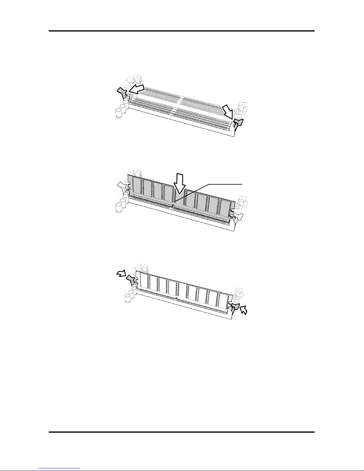
2.7.1 Memory Installation Procedure
Follow these instructions to install memory modules into the Tomcat i7221A S5151.
1. Press the locking levers in the direction shown in the following illustration.
2. Align the memory module with the socket. The memory module is keyed to fit only one
way in the socket.
3. Seat the module firmly into the socket by gently pressing down until it sits flush with the
socket. The locking levers pop up into place.
Key slot
Tomcat i7221A S5151 Chapter 2: Board Installation
2-17
http://www.tyan.com
2.8 Installing the Processor and Cooling Fan
Your Tomcat i7221A S5151 supports the latest processor technologies from Intel. Check the
TYAN website for latest processor support:
http://www.tyan.com
Processor Installation
The processor should be installed carefully. Make sure you are wearing an antistatic strap and
handle the processor as little as possible.
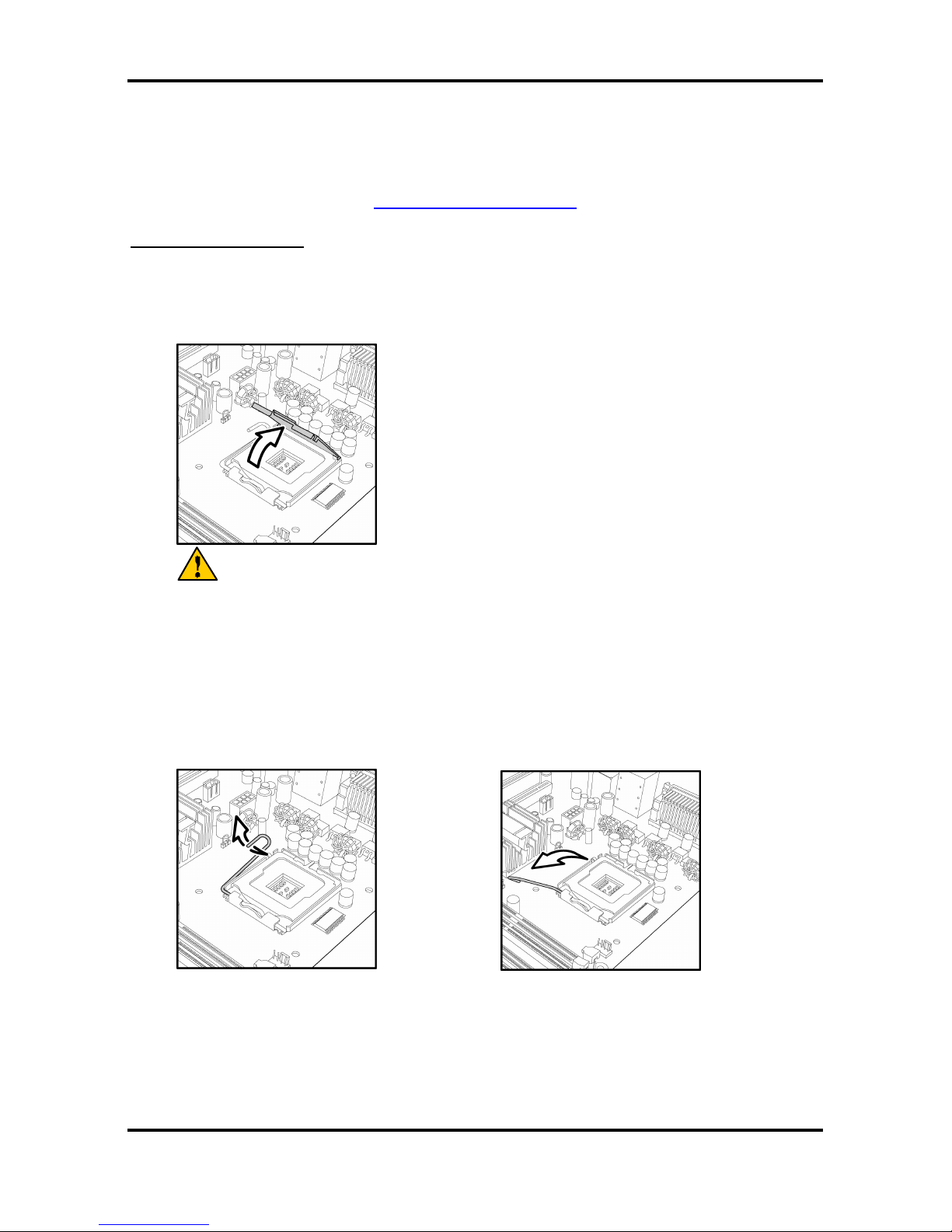
Follow these instructions to install your processor
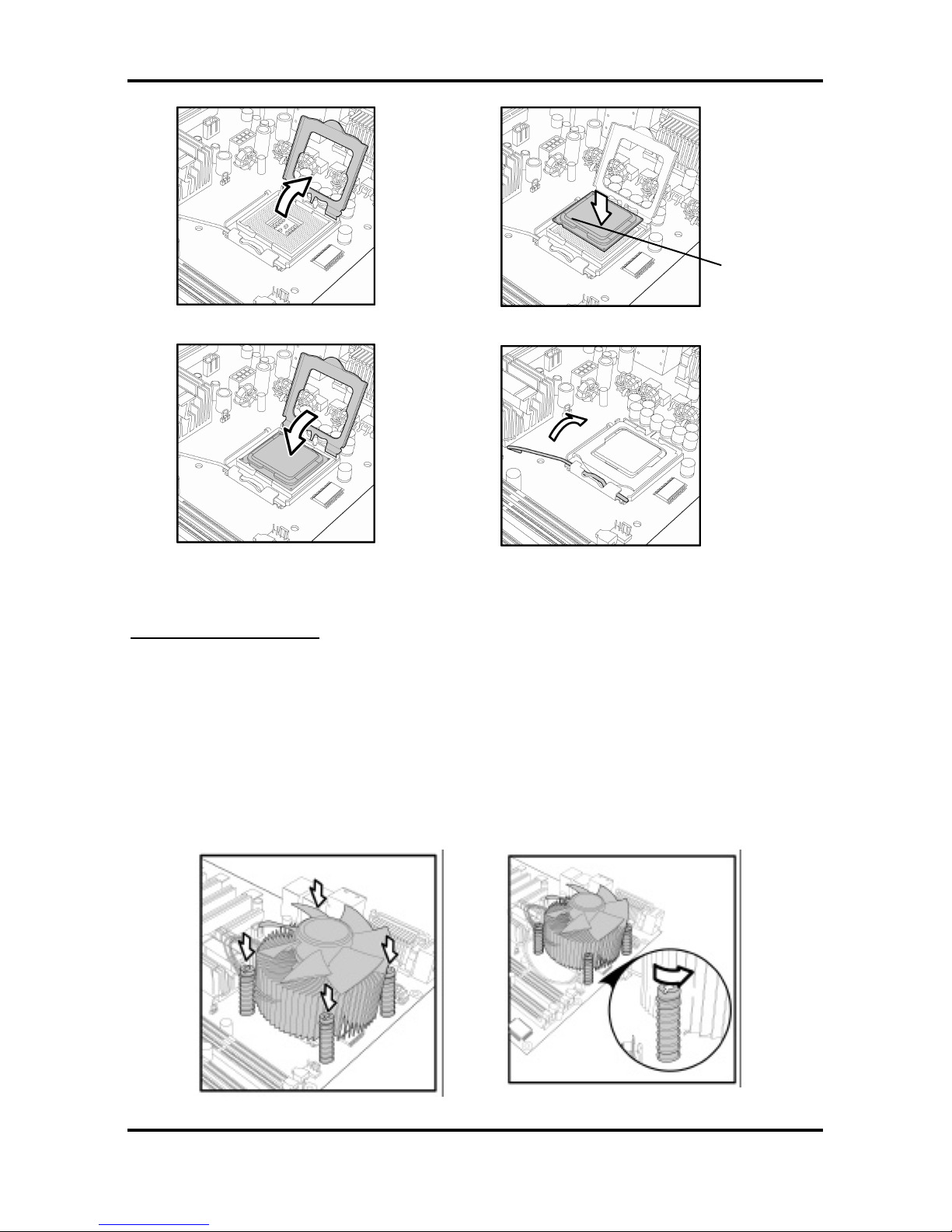
1. Locate the processor socket on the motherboard and lift the protective cover off as
shown.
WARNING:
This new processor socket designed by
Intel is easily damaged. The processor has
to be installed very carefully to prevent the
contact pins of the socket from breaking. It
is strongly recommended that the
processor installation job to be handled by
an experienced technician.
2. Pull the locking lever out of it’s locked position and let it spring into the open position.
Tomcat i7221A S5151 Chapter 2: Board Installation
2-18
http://www.tyan.com
3. Lift the metal cover to expose the socket interior and place the socket in as shown.
4. Close the cover and return the locking lever to its locked position.
Cooling Fan Installation
After you have installed the processor, the heatsink should be installed to ensure that the
processor runs efficiently and does not overheat. Use the heatsink supplied for best results.
Follow these instructions to install the heatsink shown.
1. Apply some thermal compound (also called heatsink compound or thermal grease) to
the top of the processor. Try and apply a thin, even layer over the top of the processor.
2. Align the heatsink with the four holes around the processor socket.
3. Press the heatsink down until the four screws are securely seated in the holes.
4. Use screw drive to secure the four screws.
Pin 1
Tomcat i7221A S5151 Chapter 2: Board Installation
2-19
http://www.tyan.com
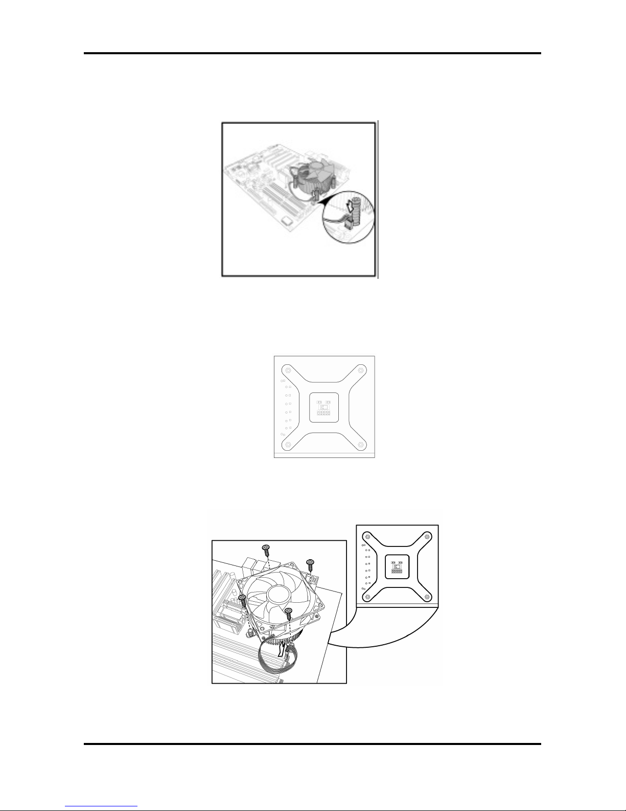
To remove the heatsink you will need to twist each of the black locking pegs until they spring
up and unlock the heatsink from the motherboard.
Remember to connect the power supply for the fan to complete the installation.
Some heat sinks require a bracket to be installed beneath the motherboard before the heat
sink is placed on the top side of the motherboard. To install a heat sink like this:
1 Turn the motherboard upside down and place the rear bracket in position with the
mounting posts poking through the corresponding holes in the motherboard.
2 Turn the motherboard the right way up, holding the bracket in place.
3 Place the heat sink assembly on top of the processor.
It should match up with the mounting holes on the rear bracket.
4 Screw the heat sink assembly into place.
If there is a fan on the heat sink you will need to connect the power lead for the fan to
one of the fan power supply pin headers on the motherboard.
Tomcat i7221A S5151 Chapter 2: Board Installation
2-20
http://www.tyan.com
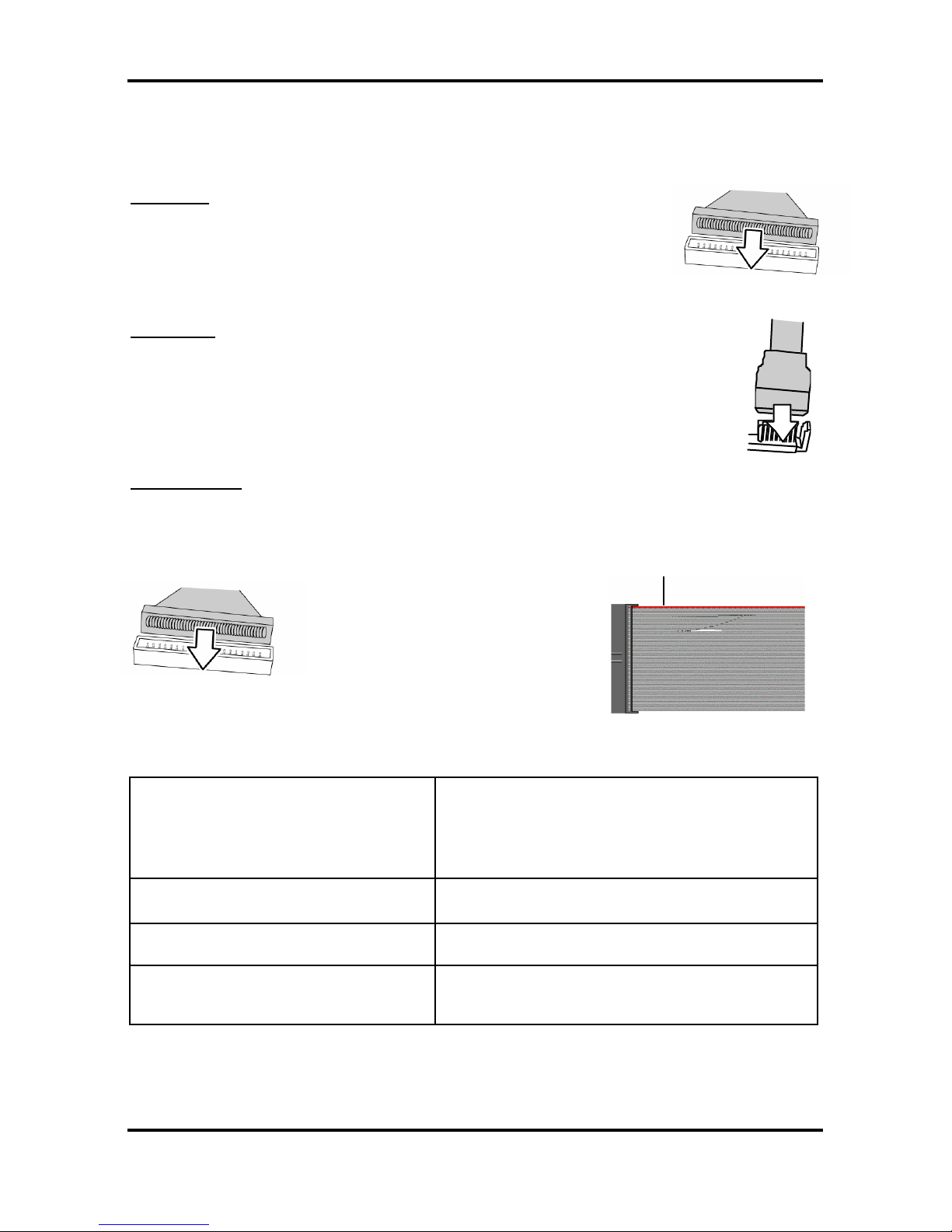
2.9 Installing Drive Cables
TIP: IDE and FDD connectors are “keyed” to only allow insertion only one way. S5151
motherboard has two on-board IDE channels, each supporting two drives.
IDE Cable
When connecting to an IDE cable to a drive, Pin 1 on the IDE cable
(usually designated by a colored wire) should be closest to the drive
power connector.
The blue end of the cable connects directly to the motherboard and the
black end of the connector goes to the IDE device.
Serial ATA
Attaching Serial ATA cables to the Serial ATA connectors are illustrated below:
Plug in one end of the Serial ATA cable into the motherboard Serial ATA
connector, and the other end into the drive. Each standard Serial ATA cable has
two connectors, one at each end. Connectors are the same on both ends.
Floppy Drives
Floppy disk drive (FDD) cables are installed the same way as IDE cables. Usually connectors
are keyed to prevent insertion the wrong way. In most cases the cable should be inserted into
the drive with pin 1 closest to the power input. FDD cables usually have a single red wire that
marks pin 1. See the diagram below.
Symptoms of incorrectly installed floppy drives
Drive is not automatically detected
Usually caused by faulty cables, cables put in
backwards or a faulty floppy drive. Try another
floppy drive or try replacing the cable. Check to
see if the onboard floppy controller is enabled in
the BIOS setup.
Drive Fail message at boot up
The cable, floppy drive or motherboard may be
faulty. Try another drive or cable.
Drive does not power on
Check power cable and cabling. A faulty power
supply or drive cable could be the problem.
Drive activity light is constantly on
Usually signifies that the cable on the drive is
inserted backwards. Reverse the cable at the
floppy drive end and try again.
Colored cable denotes pin 1
Tomcat i7221A S5151 Chapter 2: Board Installation
2-21
http://www.tyan.com
2.10 Installing Expansion Cards
Before installing add-in cards, you should ensure that they are fully compatible with your
motherboard. For this reason, we’ve provided the diagrams below, showing the expansion
slots that appear on your motherboard.
Expansion cards should be pushed firmly into the appropriate slot. Excessive force can
damage both the card and the motherboard and care sh ould be taken.
Notes
Unplug the power connector to the motherboard before performing
system hardware changes, to avoid damaging the board or expansion
cards
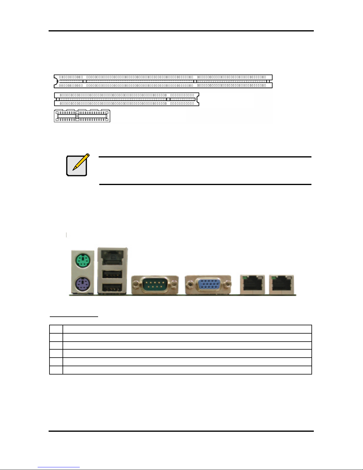
2.11 Connecting External Devices
Your new motherboard supports a number of different interfaces for connec ting peripherals.
See the diagram below. Some I/O ports may not be available with the board due to the
different configuration.
A B C D E F
Port definitions:
A PS2 mouse port (green)/ keyboard port (purple)
B 10/100 LAN + USB 2.0 ports x 2
C Serial port (green)
D VGA port (blue)
E LAN2 Gigabit Ethernet port
F LAN1 Gigabit Ethernet port
Peripheral devices can be plugged straight into any of these ports but software may be
required to complete the installation.
PCI Slot
X1 PCI Express Slot
PCI-X Slot
Tomcat i7221A S5151 Chapter 2: Board Installation
2-22
http://www.tyan.com
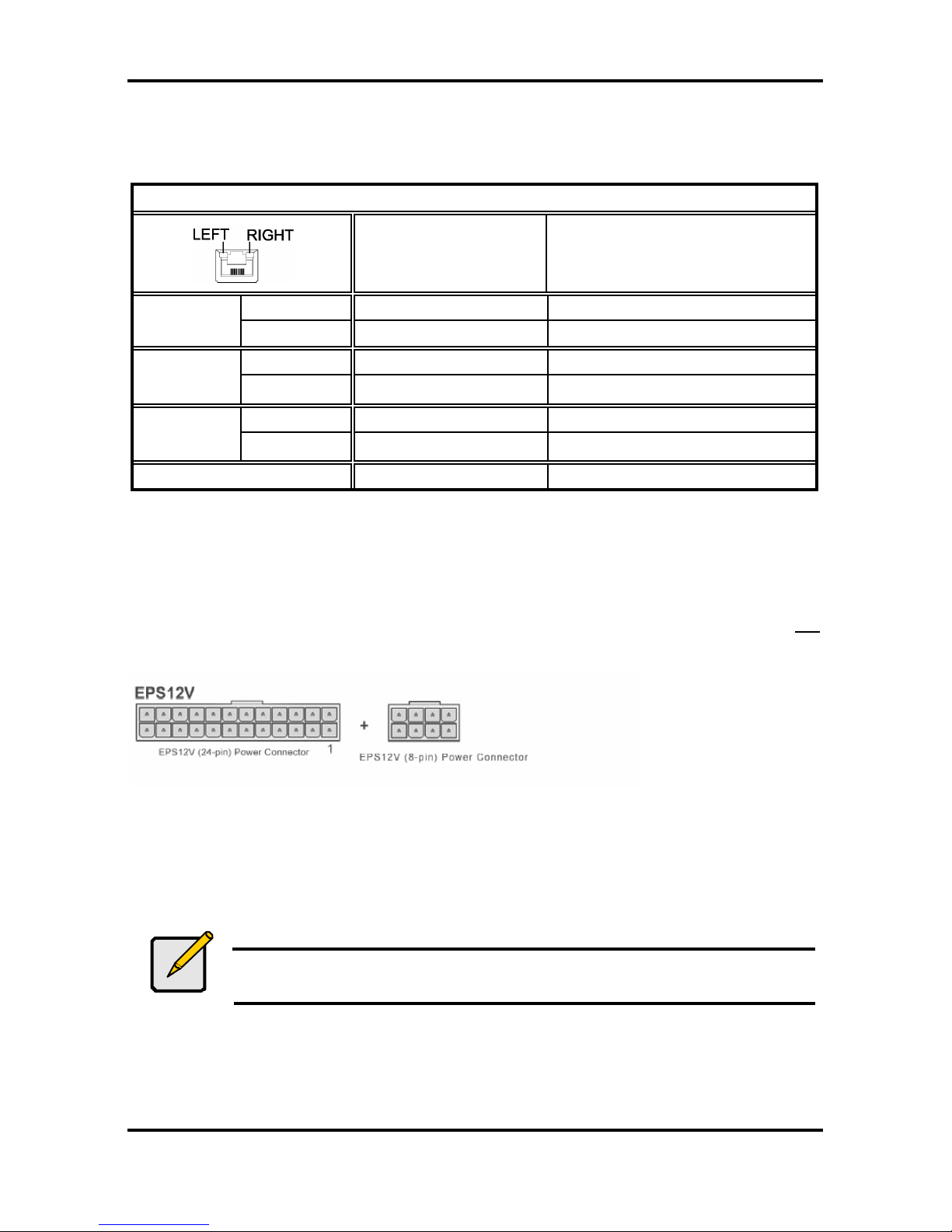
2.11.1 Onboard LAN LED Color Definition
The two onboard Ethernet ports have green and yellow LED’s to indicate LAN status. The
chart below illustrates the different LED states.
10/100/1000 Mbps LAN Link/Activity LED Scheme
Left LED Right LED
Link Green Off
10 Mbps
Active Blinking Green Off
Link Green Green
100 Mbps
Active Blinking Green Green
Link Green Orange
1000 Mbps
Active Blinking Green Orange
No Link Off Off
2.12 Installing the Power Supply
There are two power connectors on your Tomcat i7221A S5151. The Tomcat i7221A S5151
requires that you have an EPS12V power supply that has a 24-pin and an 8-pin power
connector. Please be aware that ATX 2.x, ATX12V and ATXGES power supplies are not
compatible with the board and can damage the motherboard and/or CPU(s).
Disconnect power supply from electrical outlet
1. Connect the EP12V 8-pin power connector
2. Connect the EP12V 24-pin power connector
3. Connect power cable to power supply to power outlet
Make sure you have connected both connectors before attempting to apply power to the
board.
Note
Unplug the power supply before plugging in the 24-pin and 8-pin power
cables to motherboard.

Tomcat i7221A S5151 Chapter 2: Board Installation
2-23
http://www.tyan.com
2.13 Finishing Up
Before closing up your chassis, make sure that all cables and wires are connected properly,
especially IDE cables and most importantly, jumpers. You may have difficulty powering on
your system if the motherboard jumpers are not set correctly.
If you experience difficulty, you can find help by asking your vendor for assistance. If they are
not available for assistance, please find setup information and documentation online at our
website (www.tyan.com) or by calling your vendor’s support line.
 Loading...