

TYAN Tomcat i915 S5120, S5120 User Manual

Tomcat i915 S5120 User’s Manual
i
http://www.tyan.com
Tomcat i915
///
S5120
Revision 1.00
Copyright © TYAN Computer Corporation, 2004. All rights reserved. No part of this manual
may be reproduced or translated without prior written consent from TYAN Computer Corp.
All registered and unregistered trademarks and company names contained in this manual are
property of their respective owners including, but not limited to the following.
TYAN, Tomcat i915 and S5120 are trademarks of TYAN Computer Corporation.
Intel Prescott and combinations thereof are trademarks of Intel Corporation.
Promise is a trademark of Promise Technology, Inc.
Award, AwardBIOS are trademarks of Award Software Incorporated.
Microsoft and Windows are trademarks of Microsoft Corporation.
IBM, PC, AT and PS/2 are trademarks of IBM Corporation.
VIA is a trademark of VIA Technologies, Inc.
Winbond is a trademark of Winbond Electronics Corporation.
SMSC is a trademark of Standard Microsystems Corporation.
Realtek is a trademark of Realtek Semiconductor Corporation.
Broadcom is a trademark of Broadcom Corporation.
Portable Document Format (PDF) is a trademark of Adobe Corporation.
Information contained in this document is furnished by TYAN Computer Corporation and has
been reviewed for accuracy and reliability prior to printing. TYAN assumes no liability
whatsoever, and disclaims any express or implied warranty, relating to sale and/or use of
TYAN products including liability or warranties relating to fitness for a particular purpose or
merchantability. TYAN retains the right to make changes to product descriptions and/or
specifications at any time, without notice. In no event will TYAN be held liable for any direct or
indirect, incidental or consequential damage, loss of use, loss of data or other malady resulting
from errors or inaccuracies of information contained in this document.

Tomcat i915 S5120 Table of Contents
ii
http://www.tyan.com
Table of Contents
Before you begin… .................................................................................................................iv
Chapter 1: Introduction.........................................................................................................1-1
1.1 Congratulations!......................................................................................................... 1-1
1.2 Hardware Specifications ............................................................................................1-1
Chapter 2: Board Installation ...............................................................................................2-1
2.1 Installing the Motherboard ......................................................................................... 2-1
2.1.1 Installation Notes .............................................................................................2-1
2.2 Board Image .............................................................................................................. 2-2
2.3 Block Diagram............................................................................................................ 2-3
2.4 Motherboard Components .........................................................................................2-4
2.5 Jumpers and Connectors........................................................................................... 2-5
2.5.1 Serial port: COM1 (J22) ................................................................................... 2-6
2.5.2 Serial ATA Connectors: SATA1 & SATA2 & SATA3 & SATA4 (J26/J25/J23/J24),
RAID SATA1/SATA2 (J27/J28) (on SATA RAID model only)................................... 2-6
2.5.3 CPU Fan Connector: JP1 (PFAN) ...................................................................2-7
2.5.4 Chassis Fan Connectors: JP2/JP3 (FAN1 / FAN2) .........................................2-7
2.5.5 RAID IDE Connector: JP4 (RAID-IDE1) (on SATA RAID model only) ............ 2-8
2.5.6 IEEE1394a Connector: JP5 / JP6.................................................................... 2-8
2.5.7 Front Panel Audio Connector: JP8 ..................................................................2-9
2.5.8 CD Audio Input Connector: JP9....................................................................... 2-9
2.5.9 Front Panel USB 2.0 Connectors: USB3/USB4 (JP10/JP11)........................ 2-10
2.5.10 Clear CMOS Jumper: JP13 .........................................................................2-10
2.5.11 Gigabit LAN (BCM5751) Enable/Disable Jumper: JP18.............................. 2-11
2.5.12 Chassis Fan Connector: JP19 (FAN4) ........................................................ 2-11
2.5.13 Chassis Fan Connector: JP20 (FAN3) ........................................................ 2-12
2.5.14 Front Panel System Connector: JP21 ......................................................... 2-12
2.5.15 10/100 LAN (Intel 82551QM) Enable/Disable Jumper: JP23 (optional) ...... 2-13
2.6 Mounting the Motherboard ....................................................................................... 2-13
2.7 Installing Memory..................................................................................................... 2-14
2.7.1 Memory Installation Procedure ...................................................................... 2-15
2.8 Installing the Processor and Cooling Fan ................................................................ 2-15
2.9 Installing Drive Cables .............................................................................................2-18
2.10 Installing Expansion Cards .................................................................................... 2-19
2.11 Connecting External Devices................................................................................. 2-20
2.11.1 Onboard LAN LED Color Definition .............................................................2-20
2.12 Installing the Power Supply.................................................................................... 2-21
2.13 Finishing Up ........................................................................................................... 2-21
Chapter 3: BIOS Setup..........................................................................................................3-1
3.1 About the BIOS .......................................................................................................... 3-1
3.1.1 Starting Setup .................................................................................................. 3-1
3.1.2 Setup Basics.................................................................................................... 3-1
3.1.3 Getting Help ..................................................................................................... 3-1
3.1.4 In Case of Problems ........................................................................................3-2
3.1.5 Setup Variations .............................................................................................. 3-2
3.2 Main BIOS Setup .......................................................................................................3-2
3.3 Standard CMOS Features ......................................................................................... 3-4
3.4 Advanced BIOS Features ..........................................................................................3-5
3.4.1 CPU Features .................................................................................................. 3-5
3.4.2 Boot Sequence ................................................................................................3-8
3.5 Advanced Chipsets Features................................................................................... 3-11
3.5.1 PCI Express Root Port Func.......................................................................... 3-13
3.5.2 OnChip IDE Device........................................................................................ 3-16

Tomcat i915 S5120 Table of Contents
iii
http://www.tyan.com
3.5.3 Onboard Device ............................................................................................. 3-18
3.5.4 Super IO Device............................................................................................. 3-20
3.5.5 PCI Express PM Function.............................................................................. 3-22
3.5.6 Power On Setup............................................................................................. 3-25
3.6 PnP/PCI Configurations ........................................................................................... 3-27
3.6.1 IRQ Resources ..............................................................................................3-28
3.7 PC Health Status ..................................................................................................... 3-29
3.8 Frequency/Voltage Control ......................................................................................3-30
3.9 Load Fail-Safe Defaults ........................................................................................... 3-32
3.10 Load Optimized Defaults........................................................................................ 3-33
3.11 Supervisor/User Password Setting ........................................................................ 3-33
3.12 Enter Password...................................................................................................... 3-34
3.13 Exit Selecting .........................................................................................................3-35
Chapter 4: SATA/RAID Setup (for SATA RAID model) ......................................................4-1
4.1 Getting Started........................................................................................................... 4-1
4.2 Create Your Disk Array .............................................................................................. 4-2
4.2.1 Creating a Performance Array ......................................................................... 4-2
4.2.2 Creating a Security Array with New Drives ...................................................... 4-3
4.2.3 Security Array with an Existing Data Drive ......................................................4-3
4.2.4 Security Array with Quick Initialization............................................................. 4-5
4.3 Install Software Drivers .............................................................................................. 4-6
4.3.1 Windows Server 2003...................................................................................... 4-6
4.3.2 Windows XP..................................................................................................... 4-7
4.3.3 Windows 2000 .................................................................................................4-8
4.4 Install PAM Software.................................................................................................. 4-9
4.4.1 Launch PAM and Log-in ................................................................................4-11
4.5 FastBuild™ Configuration Utility .............................................................................. 4-12
4.5.1 View the FastTrak BIOS Screen .................................................................... 4-12
4.5.2 Navigate the FastBuild Menus....................................................................... 4-13
4.5.3 Create Arrays Automatically ..........................................................................4-13
4.5.4 View Drive Assignments ................................................................................ 4-14
4.5.5 Create Arrays Manually .................................................................................4-15
4.5.6 Delete an Array .............................................................................................. 4-19
4.5.7 Rebuild a Mirrored Array................................................................................ 4-20
Chapter 5: Diagnostics.........................................................................................................5-1
5.1 Beep Codes ...............................................................................................................5-1
5.2 Flash Utility.................................................................................................................5-1
Appendix I: Glossary ............................................................................................................6-1
Appendix II: Post Error Code for BIOS ...............................................................................6-7
Technical Support .......................................................................................................... 6-12
Tomcat i915 S5120 Before you begin…
iv
http://www.tyan.com
Before you begin…
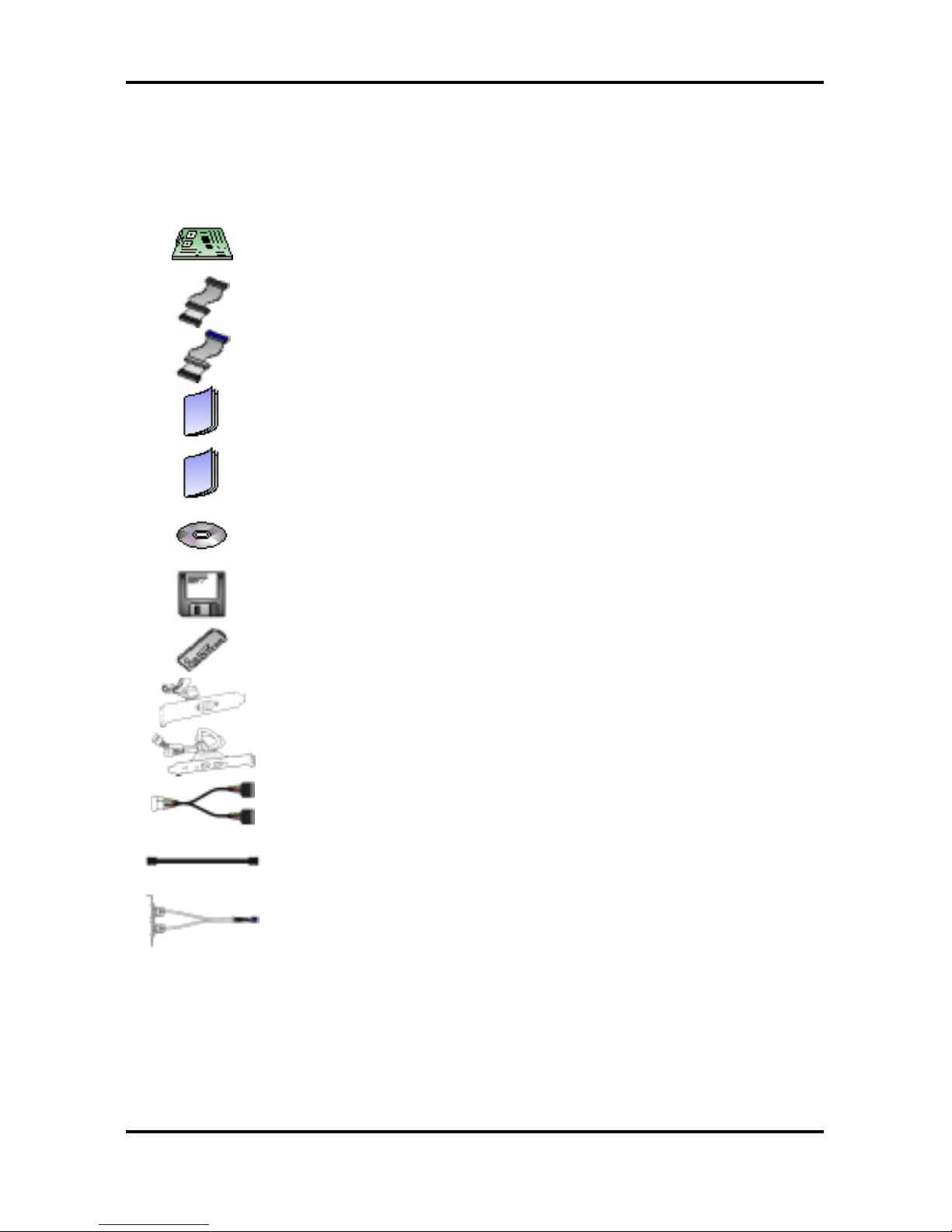
Check the package contents before you proceed.
The retail motherboard package should contain the following:
1 x Tomcat i915 S5120 motherboard
1 x 34-Pin floppy drive cable
1 x Ultra-DMA-133/100/66/33 IDE cable
(2 for models with Promise SATA RAID)
1 x Tomcat i915 S5120 User’s Manual
1 x Tomcat i915 S5120 Quick Reference Guide
1 x TYAN driver CD
2 x Promise Driver Diskette
(only for models with Promise SATA RAID)
1 x I/O shield
1 x Serial Port cable
1 x IEEE1394a cable
2 x Serial ATA power cable
4 x Serial ATA cable
1 x USB2.0 cable
If any of these items are missing, please contact your vendor or dealer for replacement before
continuing with the installation process.

Tomcat i915 S5120 Chapter 1: Introduction
1-1
http://www.tyan.com
Chapter 1: Introduction
1.1 Congratulations!
Congratulations on your purchase of the TYAN Tomcat i915 S5120, one of the most powerful
and versatile motherboard solutions available for Intel Prescott processors. Based on the
acclaimed Intel i915G chipset, the S5120 offers exceptional performance and outstanding
features. The ATX form factor S5120 features an onboard Gigabit Ethernet port, fast Ethernet
port, serial ATA, RAID, and Integrated Intel GMA 900 3D graphics engine.
For more information about this and other TYAN products, visit the TYAN Web site at
http://www.tyan.com. Product FAQs, a list of distributors and advanced BIOS information are
also available on the Web site.
1.2 Hardware Specifications
Processors
y Single Socket-T (LGA775 socket)
y Intel
“Prescott” processor with EM64T
support
y 800/533MHz FSB support
Expansion Slots
y One x16 PCI Express connector for
graphics (configurable to x1 PCI Express)
y Two x1 PCI Express connectors
y Four 32/33 PCI 2.3 slots
y Total seven usable expansion slots
Chipset
y Intel i915G (Grantsdale-G) GMCH
y Intel ICH6 South Bridge
y SMSC DME1737
System Management
y SMSC DME1737 w/ hardware monitoring
y One 3+1-pin CPU Fan header w/
tachometer input and temperature-sensing
auto fan control
y Four 3-pin system Fan headers (3 w/
tachometer input and 2 w/ temperaturesensing auto fan control)
y Temperature and voltage monitoring
y Watchdog timer
y Port 80 code display LED
Memory
y Dual memory channels
y Supports Up to four DDR-333/400 DIMM
y Up to 4GB of Unbuffered, non-ECC memory
Integrated I/O Interface
y One floppy connector
y Four USB 2.0 ports (via cable)
y One COM port (via cable)
y TYAN 2 x 9 front-panel pin header
Integrated LAN Controllers
y One Gigabit LAN controller
― Broadcom BCM5751 PCI Express
GbE LAN controller operating at x1
PCIe interface
y One 10/100 LAN controller (optional)
― Intel 82551QM 10/100 LAN
controller operating at 32bit/33MHz
PCI bus
Integrated Audio
y Realtek ALC880 7.1 channel audio
CODEC
y Intel High Definition Audio/AC’97 2.3
supported, UAA compliant
y Supports S/PDIF In/Out interface
y 2x5 pin header for front panel audio
connector
y CD-in connector
Integrated PCI IEEE1394a Controller
y VIA VT6307 PCI FireWire (1394a)
controller
y Two IEEE1394a ports (via cable)

Tomcat i915 S5120 Chapter 1: Introduction
1-2
http://www.tyan.com
Intelligent PCI IDE (ICH6)
y Single channel master mode supports two
IDE devices
y Support for ATA-100/66/33 IDE drives and
ATAPI compliant devices
Integrated Serial ATA (ICH6)
y Four Serial ATA Host controllers embedded
y Support four Serial ports running at 1.5Gb/s
Integrated 3D Graphic (i915G)
y Intel
GMA 900 3D engine embedded
y Up to 224MB shared memory support for
graphics
Rear Panel I/O ports
y Stacked PS/2 Mouse & Keyboard ports
y S/PDIF In/Out optical jacks
y One 15-pin VGA port
y One 25-pin SPP/ECP/EPP parallel port
y Six audio jacks
y Stacked two USB2.0 ports and one RJ45*
10/100 Base-T port w/ activity LED
(*optional)
y Stacked two USB2.0 ports and one RJ45
10/100/1000 Base-T port w/ activity LED
Integrated Serial ATA RAID (optional)
y Promise PDC20579 SATA RAID
controller
y 2 x SATA and 1 x Ultra ATA/133
channels
y Support up to two SATA and two ATA-
133/100 IDE drives
y Supports RAID 0, 1, 0+1
BIOS
y Award BIOS 8Mbit Flash ROM
y Supports APM 1.2 & ACPI 1.0B
y PnP, DMI 2.0, WfM 2.0 Power
Management
y Support BIOS Boot Specification v1.01
(BBS)
y Watchdog timer ready
Power
y ATX12V support, on board 4-phase
VRM
y Universal 24-pin + 8-pin power
connectors
y 4-pin auxiliary power connector
Form Factor
y ATX footprint
y 12” x 9.6” (305mm x 245mm)
Regulatory
y FCC Class B (Declaration of
Conformity)
y CE (Declaration of Conformity)
y BSMI
Note
TYAN reserves the right to add support or discontinue support for any OS
with or without notice.

Tomcat i915 S5120 Chapter 2: Board Installation
2-1
http://www.tyan.com
Chapter 2: Board Installation
2.1 Installing the Motherboard
The Tomcat i915 S5120 motherboard conforms fully to the ATX specification. Before
continuing with the installation, confirm that your chassis supports a standard ATX
motherboard. If you are unsure, contact your dealer for more information.
2.1.1 Installation Notes
This user manual contains important information and you should read it thoroughly before
attempting the installation procedure.
Precautions:
• Static electricity can damage components on your motherboard. Before touching the
product, discharge any static build up in yourself by touching a well grounded object such
as a metal water pipe or a grounded electrical appliance. TYAN recommends putting on a
good quality grounded wrist strap before removing your motherboard from the antistatic
bag.
• Disconnect your computer from the power supply before any disassembly procedure is
attempted.
• Touch the motherboard as little as possible and do not touch the bottom of the board at all.
Bending or flexing the motherboard may break delicate components or copper tracks on
the board.
• Avoid touching any of the motherboard components.
• Place the motherboard on a grounded antistatic surface or on the antistatic bag in which
the board was shipped.
• Inspect the board for damage.
Read the following sections for detailed instructions on how to install your motherboard in a
chassis and add a processor, memory, and disk drives.
Warning
Do not apply power to the board if it appears damaged.
Tomcat i915 S5120 Chapter 2: Board Installation
2-2
http://www.tyan.com
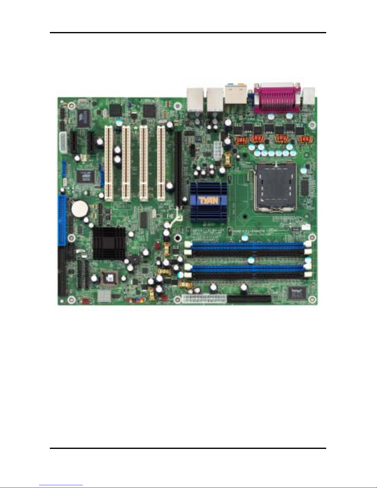
2.2 Board Image
The following is an image of the Tomcat i915 S5120.
The above photograph is purely representative. Due to engineering updates and new
board revisions, certain components may change and or be repositioned. The picture
above may or may not look exactly like the board you received.
The following page includes details on the vital components of this motherboard.
Tomcat i915 S5120 Chapter 2: Board Installation
2-3
http://www.tyan.com
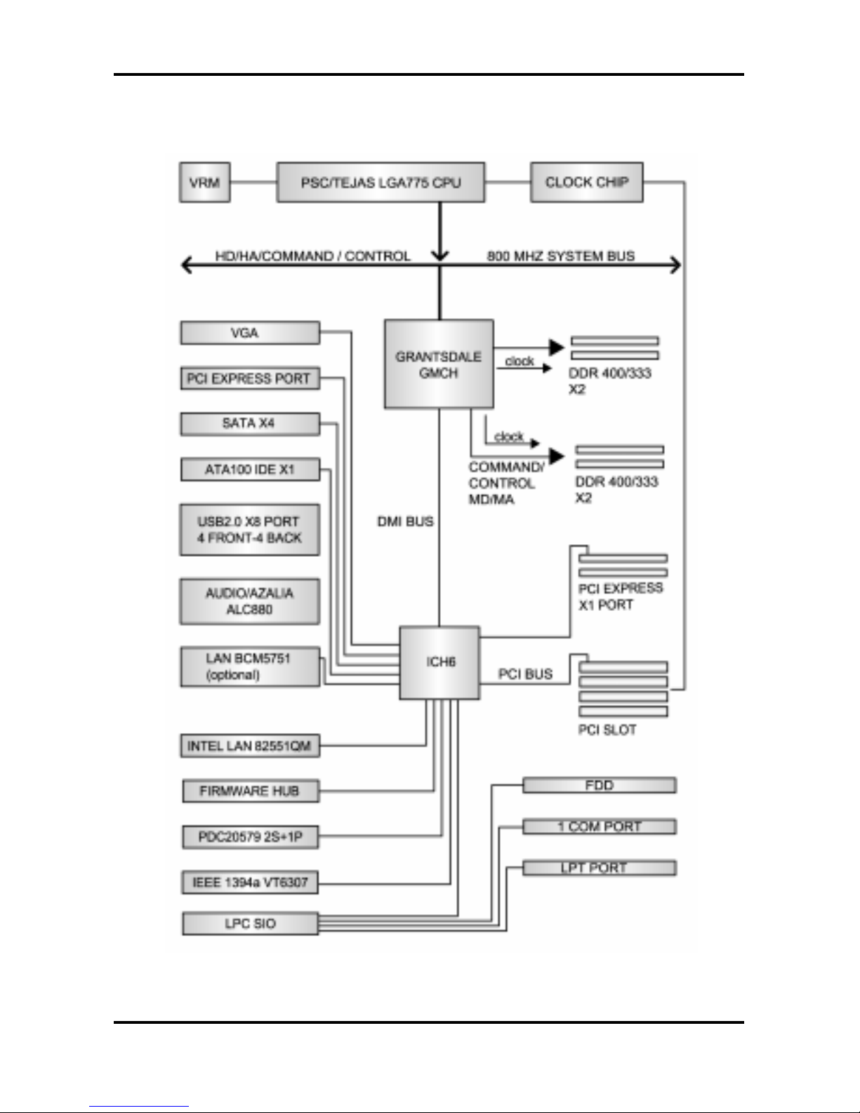
2.3 Block Diagram
The following is a block diagram of the Tomcat i915 S5120.
Tomcat i915 S5120 Chapter 2: Board Installation
2-4
http://www.tyan.com
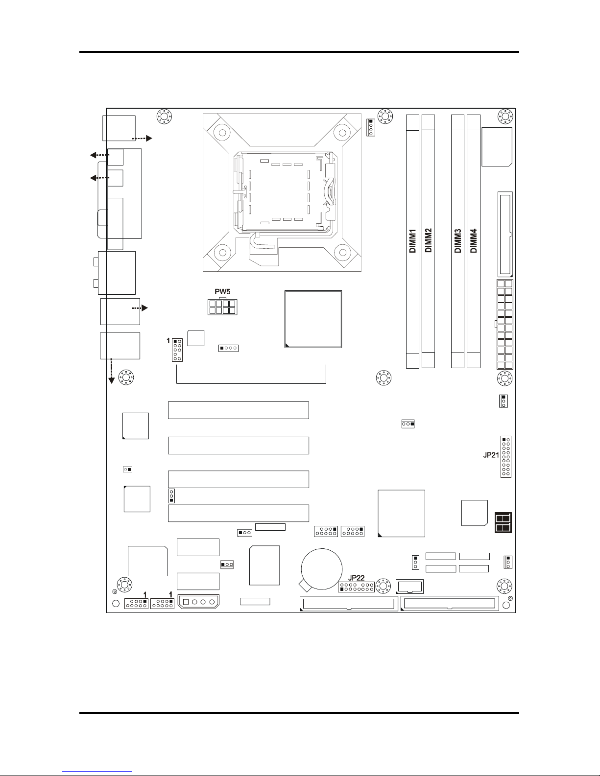
2.4 Motherboard Components
The diagram below shows the main motherboard components.
USB3
1
1
1
1
J8
(KB+Mouse)
J30
J15 (VGA)
J6
(Parall e l P o rt)
FAN2
JP3
PW8
LAN+
USB2
J33
(Audio)
ALC880
PFAN
JP1
BIOS
JP19
Intel
i915G
Intel
ICH6
32-bit 33MHz (5V) PCI PCI2
32-bit 33MHz (5V) PCI PCI3
32-bit 33MHz (5V) PCI PCI4
PCI-E2
SATA2
SATA1
FDD1 J7
JP15
RAID-IDE1 JP4 (Optional)
IDE1 J11
1
x16 PCI Express PCI-E1
SUPER
I/O
BT1
PCI-E3
USB4
1
VIA
VT6307
LED1
32-bi t 3 3 MH z (5 V )P CI PC I1
SATA3
SATA4
FAN4
Promise
PDC20579
(Optional)
JP8
1
JP9
BROADCOM
LAN
(Optional)
1
JP2
FAN1
LAN+
USB1
J22
COM1
JP18
1
1
JP13
JP5
JP6
PW3
1
FAN3
JP20
J27
J25 J24
J26
J23
S5120
J31
(SPDIF-IN)
(SPDIF-OUT)
KB(Bottom)
Mouse(Top)
USB (Bottom)
10/100 LAN (Top)
(Optional)
USB (Botto m )
GbE LAN (Top)
J28
JP10 JP11
Intel
LAN
1
JP23
1
This diagram represents the latest version of the moth erboard available at the time of
publishing. The board you receive ma y or may not look exactly like the above diagram.
Parts are not drawn to scale.
Tomcat i915 S5120 Chapter 2: Board Installation
2-5
http://www.tyan.com
2.5 Jumpers and Connectors
Jumpers and connectors are provided on your motherboard for configuration and connection
to peripherals. The following section shows you how to set your jumpers and use your
connectors.
Jumper/
Connector
Function Ref. Page
J22 COM1 Port Page 2-6
J23/J24/J25/J26 Serial ATA Connectors Page 2-6
J27/J28* RAID Serial ATA1/ATA2 Connector (optional) Page 2-6
J30/J31 S/PDIF-in and S/PDIF-out Connector
JP1 (PFAN)
CPU Fan Connector with tachometer monitoring and
fan speed control
Page 2-7
JP2/JP3
(FAN1/FAN2)
Chassis Fan Connector with tachometer monitoring and
fan speed control
Page 2-7
JP4* RAID IDE Connector (optional) Page 2-8
JP5/JP6 IEEE1394a Connector Page 2-8
JP8 Front Panel Audio Connector Page 2-9
JP9 CD Audio Input Connector Page 2-9
JP10/JP11
(USB3/USB4)
Front Panel USB Connector Page 2-10
JP13 Clear CMOS Jumper Page 2-10
JP15** Reserved
JP18 Gigabit LAN (BCM5751) Enable/Disable Jumper Page 2-11
JP19 (FAN4) Chassis Fan Connector Page 2-11
JP20 (FAN3) Chassis Fan Connector with tachometer monitoring Page 2-12
JP21 Front Panel System Connector Page 2-12
JP22** Reserved
JP23 10/100 LAN (Intel 82551QM) Enable/Disable Jumper Page 2-13
*
SATA RAID (J27/J28) and IDE RAID (JP4) are only for models with Promise SATA RAID.
**
JP15 and JP22 are reserved for OEM use only.
Jumper Legend
Jumper OFF – open (without jumper ca p)
Jumper ON – closed (with jumper cap)
Tomcat i915 S5120 Chapter 2: Board Installation
2-6
http://www.tyan.com
2.5.1 Serial port: COM1 (J22)
1 9
2 10
Signal Description
DSR
(Data-Set-Ready)
RTS
(Request-to-Send)
CTS
(Clear-to-Send)
RI
(Ring-Indicator)
NC/Key
Pin#
2 4 6 8
10
Pin#
1 3 5 7
9
USB3
1
1
1
1
J8
(KB+Mouse)
J30
J15 (VGA)
J6
(Parallel Port)
FAN2
JP3
PW8
LAN+
USB2
J33
(Audio)
ALC880
PFAN
JP1
BIOS
JP19
Intel
i915G
Intel
ICH6
32-bit 33MHz (5V) PCI PCI2
32-bit 33MHz (5V) PCI PCI3
32-bit 33MHz (5V) PCI PCI4
PCI-E2
SATA2
SATA1
FDD1 J7
JP15
RAID-IDE1 JP4 (Optional)
IDE1 J11
1
x16 PCI Express PCI-E1
SUPER
I/O
BT1
PCI-E3
USB4
1
VIA
VT6307
LED1
32-bit 33MHz (5V)PCI PCI1
SATA3
SATA4
FAN4
Promise
PDC20579
(Optional)
JP8
1
JP9
BROADCOM
LAN
(Optional)
1
JP2
FAN1
LAN+
USB1
J22
COM1
JP18
1
1
JP13
JP5
JP6
PW3
1
FAN3
JP20
J27
J25 J24
J26
J23
S5120
J31
(SPDIF-IN)
(SPDIF-OUT)
KB(Bottom )
Mouse(Top)
USB (Bo ttom)
10/100 LAN (Top)
(Optional)
USB (Bottom)
GbE LAN (Top)
J28
JP10 JP11
Intel
LAN
1
JP23
1
Signal Description
DCD
(Data Carrier Detect)
RX
(Receive-Data)
TX
(Transfer-Data)
DTR
(Data-Terminal-Ready)
GND
(Ground)
2.5.2 Serial ATA Connectors: SATA1 & SATA2 & SATA3 & SATA4 (J26/J25/J23/J24),
RAID SATA1/SATA2 (J27/J28) (on SATA RAID model only)
1 7
Pin 1 2 3 4 5 6 7
Signal GND TXP TXN GND RXN RXP GND
USB3
1
1
1
1
J8
(KB+Mouse)
J30
J15 (VGA)
J6
(Parallel Port)
FAN2
JP3
PW8
LAN+
USB2
J33
(Audio)
ALC880
PFAN
JP1
BIOS
JP19
Intel
i915G
Intel
ICH6
32-bit 33MHz (5V) PCI PCI2
32-bit 33MHz (5V) PCI PCI3
32-bit 33MHz (5V) PCI PCI4
PCI-E2
SATA2
SATA1
FDD1 J7
JP15
RAID-IDE1 JP4 (Optional)
IDE1 J11
1
x16 PCI Express PCI-E1
SUPER
I/O
BT1
PCI-E3
USB4
1
VIA
VT6307
LED1
32-bit 33MHz (5V)PCI PCI1
SATA3
SATA4
FAN4
Promise
PDC20579
(Opti onal )
JP8
1
JP9
BROADCOM
LAN
(Optional)
1
JP2
FAN1
LAN+
USB1
J22
COM1
JP18
1
1
JP13
JP5
JP6
PW3
1
FAN3
JP20
J27
J25 J24
J26
J23
S5120
J31
(SPDIF-IN)
(SPDIF-OUT)
KB(Bo t tom )
Mouse(Top)
USB (Bottom)
10/100 LA N (Top)
(Optional)
USB (Bottom)
GbE LAN (Top)
J28
JP10 JP11
Intel
LAN
1
JP23
1
Connects to the Serial ATA ready drives
via the Serial ATA cable
Along with the RAID IDE connector (JP4,
see page 2-8), J27/J28 support RAID 0, 1
and 0+1 through the on board SATA RAID
controller chip. You may use the RAID
feature to setup a disk array configuration
or to support additional drives
Tomcat i915 S5120 Chapter 2: Board Installation
2-7
http://www.tyan.com
2.5.3 CPU Fan Connector: JP1 (PFAN)
+12V
V3P3
Speed Control
Tachometer
USB3
1
1
1
1
J8
(KB+Mouse)
J30
J15 (VGA)
J6
(Parallel Port)
FAN2
JP3
PW8
LAN+
USB2
J33
(Audio)
ALC880
PFAN
JP1
BIOS
JP19
Intel
i915G
Intel
ICH6
32-bit 33MHz (5V) PCI PCI2
32-bit 33MHz (5V) PCI PCI3
32-bit 33MHz (5V) PCI PCI4
PCI-E2
SATA2
SATA1
FDD1 J7
JP15
RAID-IDE1 JP4 (Optional)
IDE1 J11
1
x16 PCI Express PCI-E1
SUPER
I/O
BT1
PCI-E3
USB4
1
VIA
VT6307
LED1
32-bit 33MHz (5V)PCI PCI1
SATA3
SATA4
FAN4
Promise
PDC20579
(Optional)
JP8
1
JP9
BROADCOM
LAN
(Optional)
1
JP2
FAN1
LAN+
USB1
J22
COM1
JP18
1
1
JP13
JP5 JP6
PW3
1
FAN3
JP20
J27
J25 J24
J26
J23
S5120
J31
(SPDIF-IN)
(SPDIF-OU T)
KB(Bottom )
Mouse(Top)
USB (Bo ttom)
10/100 LAN (Top)
(Optional)
USB (Bottom)
GbE LAN (Top)
J28
JP10 JP11
Intel
LAN
1
JP23
1
Use this header to connect the processor
cooling fan to your motherboard to keep
the system stable and reliable.
This connector supports the tachometer
monitoring and auto fan speed control.
2.5.4 Chassis Fan Connectors: JP2/JP3 (FAN1 / FAN2)
+12V
Speed Control
Ta c h omete r
USB3
1
1
1
1
J8
(KB+Mouse)
J30
J15 (VGA)
J6
(Parallel Port)
FAN2
JP3
PW8
LAN+
USB2
J33
(Audio)
ALC880
PFAN
JP1
BIOS
JP19
Intel
i915G
Intel
ICH6
32-bit 33MHz (5V) PCI PCI2
32-bit 33MHz (5V) PCI PCI3
32-bit 33MHz (5V) PCI PCI4
PCI-E2
SATA2
SATA1
FDD1 J7
JP15
RAID-IDE1 JP4 (Optional)
IDE1 J11
1
x16 PCI Express PCI-E1
SUPER
I/O
BT1
PCI-E3
USB4
1
VIA
VT6307
LED1
32-bit 33MHz (5V)PCI PCI1
SATA3
SATA4
FAN4
Promise
PDC20579
(Optional)
JP8
1
JP9
BROADCOM
LAN
(Optional)
1
JP2
FAN1
LAN+
USB1
J22
COM1
JP18
1
1
JP13
JP5
JP6
PW3
1
FAN3
JP20
J27
J25 J24
J26
J23
S5120
J31
(SPDIF-IN)
(SPDIF-OUT)
KB(Bottom)
Mouse(Top)
USB (Bottom)
10/100 LA N (Top )
(Optional)
USB (Bottom)
GbE LAN (Top)
J28
JP10 JP11
Intel
LAN
1
JP23
1
Use these headers to connect the chassis
cooling fans to your motherboard to keep
the system stable and reliable.
These connectors support the tachometer
monitoring and auto fan speed control.
Tomcat i915 S5120 Chapter 2: Board Installation
2-8
http://www.tyan.com
2.5.5 RAID IDE Connector: JP4 (RAID-IDE1) (on SATA RAID model only)
USB3
1
1
1
1
J8
(KB+Mouse)
J30
J15 (VGA)
J6
(Parallel Port)
FAN2
JP3
PW8
LAN+
USB2
J33
(Audio)
ALC880
PFAN
JP1
BIOS
JP19
Intel
i915G
Intel
ICH6
32-bit 33MHz (5V) PCI PCI2
32-bit 33MHz (5V) PCI PCI3
32-bit 33MHz (5V) PCI PCI4
PCI-E2
SATA2
SATA1
FDD1 J7
JP15
RAID-IDE1 JP4 (Optional) IDE1 J11
1
x16 PCI Express PCI-E1
SUPER
I/O
BT1
PCI-E3
USB4
1
VIA
VT6307
LED1
32-bit 33MHz (5V)PC I PCI1
SATA3
SATA4
FAN4
Promise
PDC20579
(Optional)
JP8
1
JP9
BROADCOM
LAN
(Optional)
1
JP2
FAN1
LAN+
USB1
J22
COM1
JP18
1
1
JP13
JP5
JP6
PW3
1
FAN3
JP20
J27
J25 J24
J26
J23
S5120
J31
(SPDIF-IN)
(SPDIF-OUT)
KB(B ot to m )
Mouse(Top)
USB (Bo ttom)
10/100 LAN (Top)
(Optional)
USB (Bottom)
GbE LAN (Top)
J28
JP10 JP11
Intel
LAN
1
JP23
1
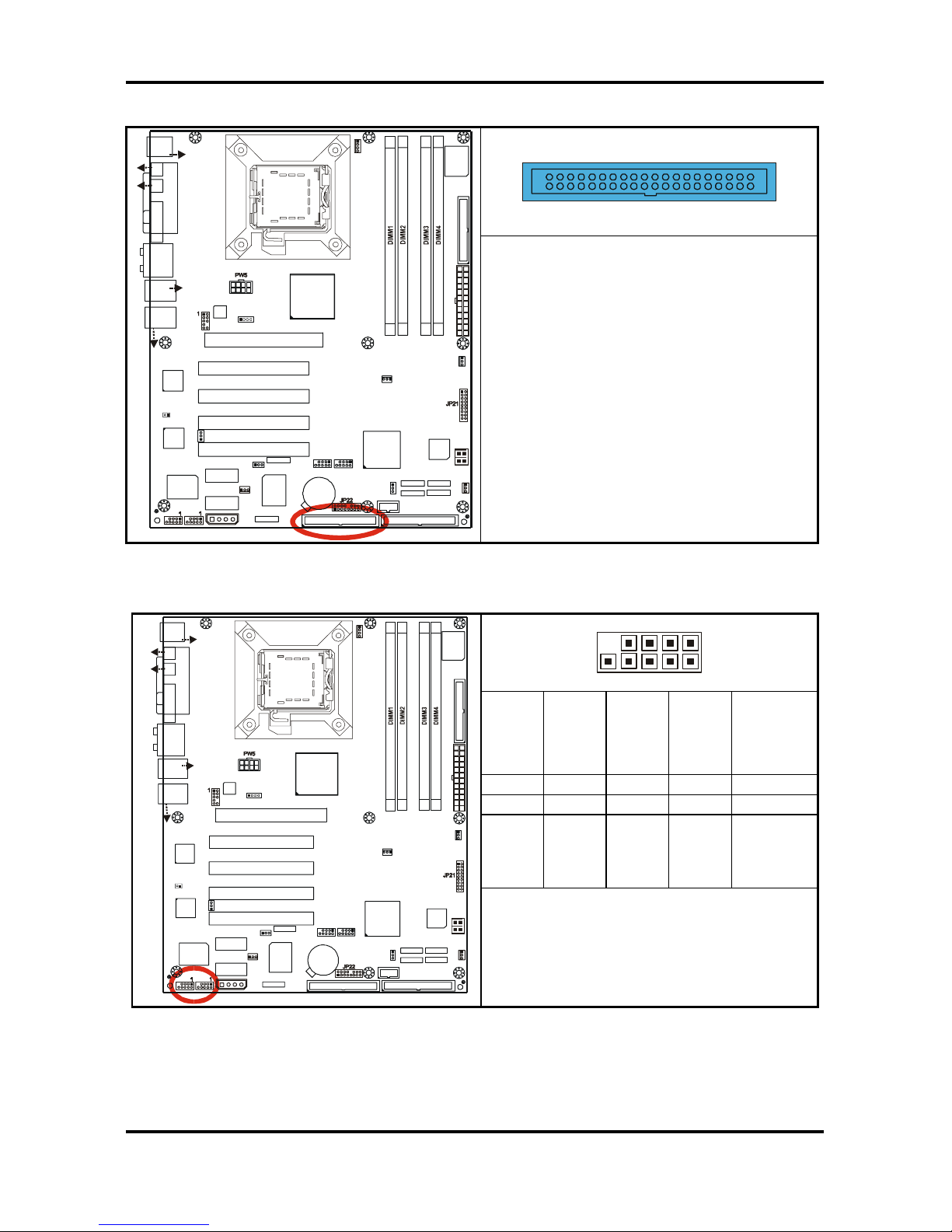
Supports RAID 0, 1, 0+1 along with the
J27 (RAID SATA1) and J28 (RAID SATA2)
through the on board SATA RAID
controller chip.
2.5.6 IEEE1394a Connector: JP5 / JP6
10 2
9 1
NC
NC
XTPB+
GND
XTPA+
9 7 5 3 1
10 8 6 4 2
GND
VCC
XTPB-
GND
XTPA-
USB3
1
1
1
1
J8
(KB+Mouse)
J30
J15 (VGA)
J6
(Parallel Port)
FAN2
JP3
PW8
LAN+
USB2
J33
(Audio)
ALC880
PFAN
JP1
BIOS
JP19
Intel
i915G
Intel
ICH6
32-bit 33MHz (5V) PCI PCI2
32-bit 33MHz (5V) PCI PCI3
32-bit 33MHz (5V) PCI PCI4
PCI-E2
SATA2
SATA1
FDD1 J7
JP15
RAID-IDE1 JP4 (Optional)
IDE1 J11
1
x16 PCI Express PCI-E1
SUPER
I/O
BT1
PCI-E3
USB4
1
VIA
VT6307
LED1
32-bit 33MHz (5V)PCI PCI1
SATA3
SATA4
FAN4
Promise
PDC20579
(Optional)
JP8
1
JP9
BROADCOM
LAN
(Optional)
1
JP2
FAN1
LAN+
USB1
J22
COM1
JP18
1
1
JP13
JP5
JP6
PW3
1
FAN3
JP20
J27
J25 J24
J26
J23
S5120
J31
(SPDIF-IN)
(SPDIF-OUT)
KB(Bottom)
Mouse(Top)
USB (Bo ttom)
10/100 LAN (Top)
(Optional)
USB (Bo ttom)
GbE LAN (Top)
J28
JP10 JP11
Intel
LAN
1
JP23
1
Use these headers to connect IEEE1394a
(FireWire) type device via the enclosed
1394a cable.
Tomcat i915 S5120 Chapter 2: Board Installation
2-9
http://www.tyan.com
2.5.7 Front Panel Audio Connector: JP8
1
9
2
10
1L 1 2 GND
1R 3 4 Presence
2R 5 6 AUD FP JS
AUD FP JS 7 8 NC
2L 9 10 AUD VREF
USB3
1
1
1
1
J8
(KB+Mouse)
J30
J15 (VGA)
J6
(Parallel Port)
FAN2
JP3
PW8
LAN+
USB2
J33
(Audio)
ALC880
PFAN
JP1
BIOS
JP19
Intel
i915G
Intel
ICH6
32-bit 33MHz (5V) PCI PCI2
32-bit 33MHz (5V) PCI PCI3
32-bit 33MHz (5V) PCI PCI4
PCI-E2
SATA2
SATA1
FDD1 J7
JP15
RAID-IDE1 JP4 (Optional)
IDE1 J11
1
x16 PCI Express PCI-E1
SUPER
I/O
BT1
PCI-E3
USB4
1
VIA
VT6307
LED1
32-bit 33MHz (5V)PCI PCI1
SATA3
SATA4
FAN4
Promise
PDC20579
(Optional)
JP8
1
JP9
BROADCOM
LAN
(Optional)
1
JP2
FAN1
LAN+
USB1
J22
COM1
JP18
1
1
JP13
JP5
JP6
PW3
1
FAN3
JP20
J27
J25 J24
J26
J23
S5120
J31
(SPDIF-IN)
(SPDIF-OU T)
KB(B ottom )
Mouse(Top)
USB (Bo ttom)
10/100 LAN (Top)
(Optional)
USB (Bo tto m )
GbE LAN (Top)
J28
JP10 JP11
Intel
LAN
1
JP23
1
Use this header to connect with the front
panel audio outputs.
2.5.8 CD Audio Input Connector: JP9
41
Pin_1 Pin_2 Pin_3 Pin_4
CD_In _Left
GND
GND
CD_In_Right
USB3
1
1
1
1
J8
(KB+Mouse)
J30
J15 (VGA)
J6
(Parallel Port)
FAN2
JP3
PW8
LAN+
USB2
J33
(Audio)
ALC880
PFAN
JP1
BIOS
JP19
Intel
i915G
Intel
ICH6
32-bit 33MHz (5V) PCI PCI2
32-bit 33MHz (5V) PCI PCI3
32-bit 33MHz (5V) PCI PCI4
PCI-E2
SATA2
SATA1
FDD1 J7
JP15
RAID-IDE1 JP4 (Optional)
IDE1 J11
1
x16 PCI Express PCI-E1
SUPER
I/O
BT1
PCI-E3
USB4
1
VIA
VT6307
LED1
32-bit 33MHz (5V)PCI PCI1
SATA3
SATA4
FAN4
Promise
PDC20579
(Optional)
JP8
1
JP9
BROADCOM
LAN
(Optional)
1
JP2
FAN1
LAN+
USB1
J22
COM1
JP18
1
1
JP13
JP5
JP6
PW3
1
FAN3
JP20
J27
J25 J24
J26
J23
S5120
J31
(SPDIF-IN)
(SPDI F-OUT)
KB(Bottom )
Mouse(Top)
USB (Bottom)
10/100 LA N (Top)
(Optional)
USB (Bo ttom )
GbE LAN (Top)
J28
JP10 JP11
Intel
LAN
1
JP23
1
Use this header to connect to the audio
output of a CD-ROM drive via an optional
CD audio cable so that you can listen to
the audio CDs through the integrated
audio chip on the motherboard.

Tomcat i915 S5120 Chapter 2: Board Installation
2-10
http://www.tyan.com
2.5.9 Front Panel USB 2.0 Connectors: USB3/USB4 (JP10/JP11)
10 2
9 1
GND
GND
Data 1+
Data 1 -
+5V
9 7 5 3 1
10 8 6 4 2
GND
GND
Data 2+
Data 2 -
+5V
USB3
1
1
1
1
J8
(KB+Mouse)
J30
J15 (VGA)
J6
(Parallel Port)
FAN2
JP3
PW8
LAN+
USB2
J33
(Audio)
ALC880
PFAN
JP1
BIOS
JP19
Intel
i915G
Intel
ICH6
32-bit 33MHz (5V) PCI PCI2
32-bit 33MHz (5V) PCI PCI3
32-bit 33MHz (5V) PCI PCI4
PCI-E2
SATA2
SATA1
FDD1 J7
JP15
RAID-IDE1 JP4 (Optional)
IDE1 J11
1
x16 PCI Express PCI-E1
SUPER
I/O
BT1
PCI-E3
USB4
1
VIA
VT6307
LED1
32-bit 33MHz (5V)PCI PCI1
SATA3
SATA4
FAN4
Promise
PDC20579
(Optional)
JP8
1
JP9
BROADCOM
LAN
(Optional)
1
JP2
FAN1
LAN+
USB1
J22
COM1
JP18
1
1
JP13
JP5
JP6
PW3
1
FAN3
JP20
J27
J25 J24
J26
J23
S5120
J31
(SPDIF-IN)
(SPDIF-OU T)
KB(Bottom)
Mouse(Top)
USB (Bo ttom)
10/100 LAN (Top)
(Optional)
USB (Bo ttom)
GbE LAN (Top)
J28
JP10 JP11
Intel
LAN
1
JP23
1
Use these headers to Connect to the USB
devices via the enclosed USB cable.
2.5.10 Clear CMOS Jumper: JP13
3
1
Default
3
1
Clear
USB3
1
1
1
1
J8
(KB+Mouse)
J30
J15 (VGA)
J6
(Parallel Port)
FAN2
JP3
PW8
LAN+
USB2
J33
(Audio)
ALC880
PFAN
JP1
BIOS
JP19
Intel
i915G
Intel
ICH6
32-bit 33MHz (5V) PCI PCI2
32-bit 33MHz (5V) PCI PCI3
32-bit 33MHz (5V) PCI PCI4
PCI-E2
SATA2
SATA1
FDD1 J7
JP15
RAID-IDE1 JP4 (Optional)
IDE1 J11
1
x16 PCI Express PCI-E1
SUPER
I/O
BT1
PCI-E3
USB4
1
VIA
VT6307
LED1
32-bit 33MHz (5V)PCI PCI1
SATA3
SATA4
FAN4
Promise
PDC20579
(Optional)
JP8
1
JP9
BROADCOM
LAN
(Optional)
1
JP2
FAN1
LAN+
USB1
J22
COM1
JP18
1
1
JP13
JP5
JP6
PW3
1
FAN3
JP20
J27
J25 J24
J26
J23
S5120
J31
(SPDIF-IN)
(SPDIF-OU T)
KB(B ottom )
Mouse(Top)
USB (Bo ttom)
10/100 LAN (Top)
(Optional)
USB (Bo ttom )
GbE LAN (Top)
J28
JP10 JP11
Intel
LAN
1
JP23
1
Use this jumper when you forgot your
system/setup password or need to clear
system BIOS setting.
How to clear the CMOS data
- Power off system and disconnect
power supply from AC source
- Use jumper cap to close Pin_2 and 3
for several seconds to Clear CMOS
- Replace jumper cap to close Pin_1
and 2 (default setting)
- Reconnect power supply to AC
source
- Power on system
Tomcat i915 S5120 Chapter 2: Board Installation
2-11
http://www.tyan.com
2.5.11 Gigabit LAN (BCM5751) Enable/Disable Jumper: JP18
1
OPEN
1
CLOSED (Default)
USB3
1
1
1
1
J8
(KB+Mouse)
J30
J15 (VGA)
J6
(Parallel Port)
FAN2
JP3
PW8
LAN+
USB2
J33
(Audio)
ALC880
PFAN
JP1
BIOS
JP19
Intel
i915G
Intel
ICH6
32-bit 33MHz (5V) PCI PCI2
32-bit 33MHz (5V) PCI PCI3
32-bit 33MHz (5V) PCI PCI4
PCI-E2
SATA2
SATA1
FDD1 J7
JP15
RAID-IDE1 JP4 (Optional)
IDE1 J11
1
x16 PCI Express PCI-E1
SUPER
I/O
BT1
PCI-E3
USB4
1
VIA
VT6307
LED1
32-bit 33MHz (5V)PCI PCI1
SATA3
SATA4
FAN4
Promise
PDC20579
(Optional)
JP8
1
JP9
BROADCOM
LAN
(Optional)
1
JP2
FAN1
LAN+
USB1
J22
COM1
JP18
1
1
JP13
JP5
JP6
PW3
1
FAN3
JP20
J27
J25 J24
J26
J23
S5120
J31
(SPDIF-IN)
(SPDIF-OUT)
KB(Bottom)
Mouse(Top)
USB (Bo ttom)
10/100 LAN (Top)
(Optional)
USB (Bottom)
GbE LAN (Top)
J28
JP10 JP11
Intel
LAN
1
JP23
1
Disable the on board Gigabit LAN function
by removing the jumper cap if needed.
2.5.12 Chassis Fan Connector: JP19 (FAN4)
+12V
NCGND
USB3
1
1
1
1
J8
(KB+Mouse)
J30
J15 (VGA)
J6
(Parallel Port)
FAN2
JP3
PW8
LAN+
USB2
J33
(Audio)
ALC880
PFAN
JP1
BIOS
JP19
Intel
i915G
Intel
ICH6
32-bit 33MHz (5V) PCI PCI2
32-bit 33MHz (5V) PCI PCI3
32-bit 33MHz (5V) PCI PCI4
PCI-E2
SATA2
SATA1
FDD1 J7
JP15
RAID-IDE1 JP4 (Optional)
IDE1 J11
1
x16 PCI Express PCI-E1
SUPER
I/O
BT1
PCI-E3
USB4
1
VIA
VT6307
LED1
32-bit 33MHz (5V)PCI PCI1
SATA3
SATA4
FAN4
Promise
PDC20579
(Optional)
JP8
1
JP9
BROADCOM
LAN
(Optional)
1
JP2
FAN1
LAN+
USB1
J22
COM1
JP18
1
1
JP13
JP5
JP6
PW3
1
FAN3
JP20
J27
J25 J24
J26
J23
S5120
J31
(SPDIF-IN)
(SPDIF-OUT)
KB(Bottom )
Mouse(Top)
USB (Bo ttom)
10/100 LAN (Top)
(Optional)
USB (Bottom)
GbE LAN (Top)
J28
JP10 JP11
Intel
LAN
1
JP23
1
Use this header to connect the chassis
cooling fan to your motherboard to keep
the system stable and reliable.
Tomcat i915 S5120 Chapter 2: Board Installation
2-12
http://www.tyan.com
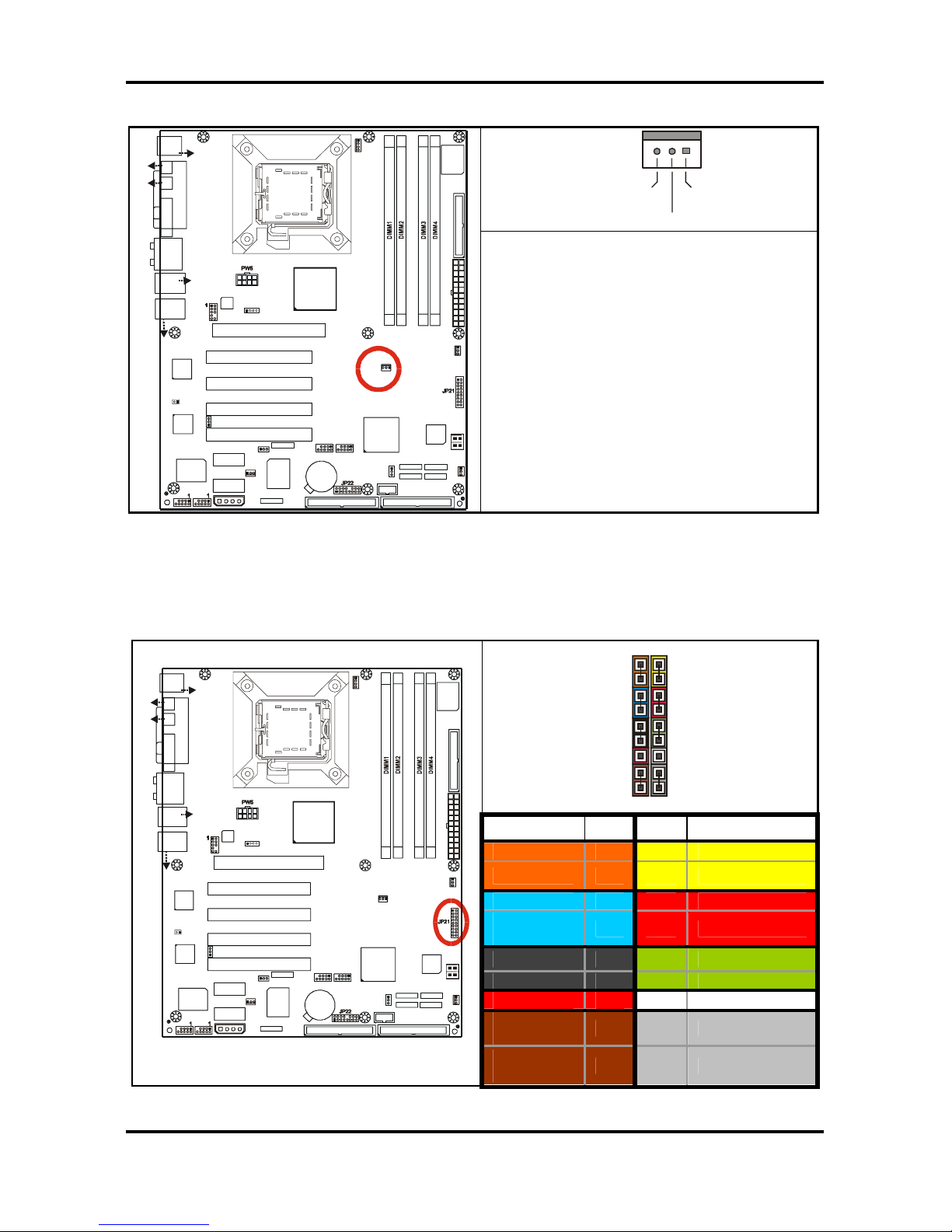
2.5.13 Chassis Fan Connector: JP20 (FAN3)
+12V
GND
Ta c h omet er
USB3
1
1
1
1
J8
(KB+Mouse)
J30
J15 (VGA)
J6
(Parallel Port)
FAN2
JP3
PW8
LAN+
USB2
J33
(Audio)
ALC880
PFAN
JP1
BIOS
JP19
Intel
i915G
Intel
ICH6
32-bit 33MHz (5V) PCI PCI2
32-bit 33MHz (5V) PCI PCI3
32-bit 33MHz (5V) PCI PCI4
PCI-E2
SATA2
SATA1
FDD1 J7
JP15
RAID-IDE1 JP4 (Optional)
IDE1 J11
1
x16 PCI Express PCI-E1
SUPER
I/O
BT1
PCI-E3
USB4
1
VIA
VT6307
LED1
32-bit 33MHz (5V)PCI PCI1
SATA3
SATA4
FAN4
Promise
PDC20579
(Optional)
JP8
1
JP9
BROADCOM
LAN
(Optional)
1
JP2
FAN1
LAN+
USB1
J22
COM1
JP18
1
1
JP13
JP5
JP6
PW3
1
FAN3
JP20
J27
J25 J24
J26
J23
S5120
J31
(SPDIF-IN)
(SPDIF-OUT)
KB(Bottom )
Mouse(Top)
USB (Bo ttom)
10/100 LAN (Top)
(Optional)
USB (Bottom)
GbE LAN (Top)
J28
JP10 JP11
Intel
LAN
1
JP23
1
Use this header to connect the chassis
cooling fans to your motherboard to keep
the system stable and reliable.
This connector supports the tachometer
monitoring.
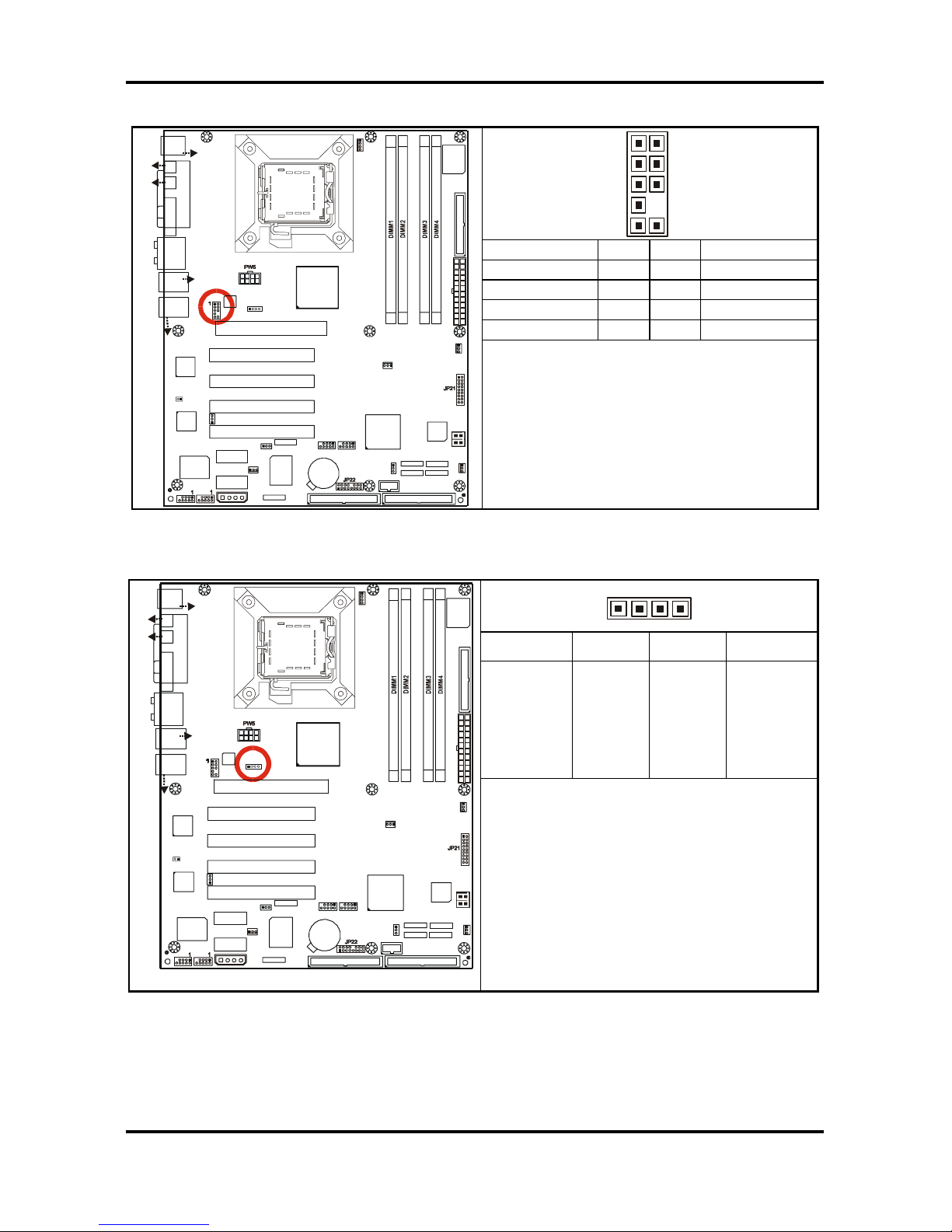
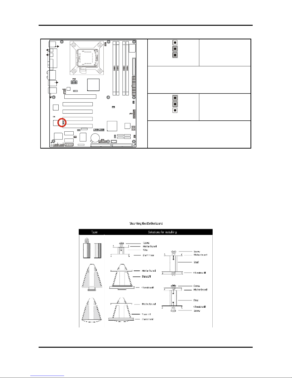
2.5.14 Front Panel System Connector: JP21
Your chassis will usually come with connectors to install onto the motherboard, such as HD
and Power LEDs. The Front Panel Connector (JP21) has been implemented for such
purposes.
1 2
17 18
Function PIN PIN Function
HD_LED+ 1 2 PWR+
HD_LED- 3 4 PWRGND 5 6 Power Button
Reset
Button
7 8 GND
+5V 9 10 Sleep Button
NIMI 11 12 GND
+5VSB 13 14 NC
SMBUS
Data
15 16 GND
USB3
1
1
1
1
J8
(KB+Mouse)
J30
J15 (VGA)
J6
(Parallel Port)
FAN2
JP3
PW8
LAN+
USB2
J33
(Audio)
ALC880
PFAN
JP1
BIOS
JP19
Intel
i915G
Intel
ICH6
32-bit 33MHz (5V) PCI PCI2
32-bit 33MHz (5V) PCI PCI3
32-bit 33MHz (5V) PCI PCI4
PCI-E2
SATA2
SATA1
FDD1 J7
JP15
RAID-IDE1 JP4 (Optional)
IDE1 J11
1
x16 PCI Express PCI-E1
SUPER
I/O
BT1
PCI-E3
USB4
1
VIA
VT6307
LED1
32-bit 33MHz (5V)PCI PCI1
SATA3
SATA4
FAN4
Promise
PDC20579
(Optional)
JP8
1
JP9
BROADCOM
LAN
(Optional)
1
JP2
FAN1
LAN+
USB1
J22
COM1
JP18
1
1
JP13
JP5
JP6
PW3
1
FAN3
JP20
J27
J25 J24
J26
J23
S5120
J31
(SPDIF-IN)
(SPDIF-OU T )
KB(Bottom)
Mouse(Top)
USB (Bottom)
10/100 LA N (Top)
(Optional)
USB (Bottom)
GbE LAN (Top)
J28
JP10 JP11
Intel
LAN
1
JP23
1
SMBUS
Clock
17 18 INTRU#
Tomcat i915 S5120 Chapter 2: Board Installation
2-13
http://www.tyan.com
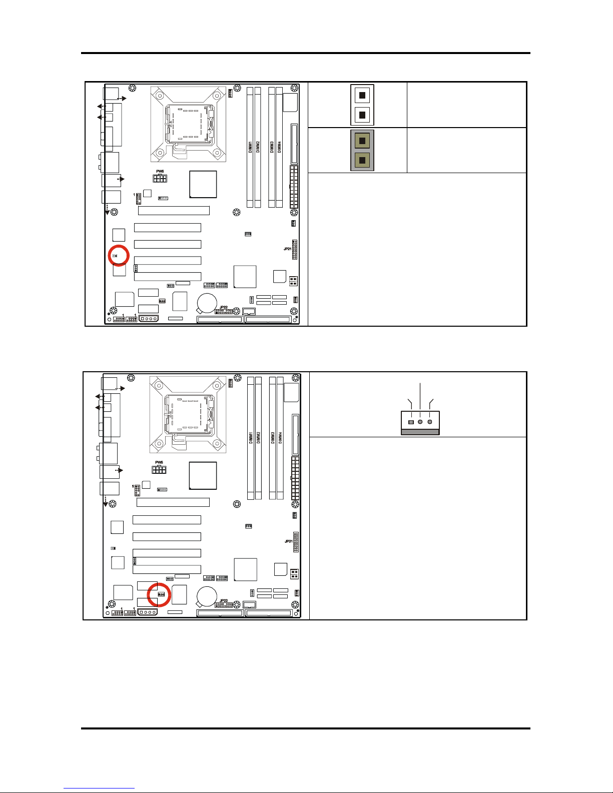
2.5.15 10/100 LAN (Intel 82551QM) Enable/Disable Jumper: JP23 (optional)
3
1
Pin 1 – 2 Closed
(Default)
To enable on-board 10/100 Ethernet
3
1
Pin 2 – 3 Closed
USB3
1
1
1
1
J8
(KB+Mouse)
J30
J15 (VGA)
J6
(Parallel Port)
FAN2
JP3
PW8
LAN+
USB2
J33
(Audio)
ALC880
PFAN
JP1
BIOS
JP19
Intel
i915G
Intel
ICH6
32-bit 33MHz (5V) PCI PCI2
32-bit 33MHz (5V) PCI PCI3
32-bit 33MHz (5V) PCI PCI4
PCI-E2
SATA2
SATA1
FDD1 J7
JP15
RAID-IDE1 JP4 (Optional)
IDE1 J11
1
x16 PCI Express PCI-E1
SUPER
I/O
BT1
PCI-E3
USB4
1
VIA
VT6307
LED1
32-bit 33MHz (5V)PCI PCI1
SATA3
SATA4
FAN4
Promise
PDC20 579
(Optional)
JP8
1
JP9
BROADCOM
LAN
(Optional)
1
JP2
FAN1
LAN+
USB1
J22
COM1
JP18
1
1
JP13
JP5
JP6
PW3
1
FAN3
JP20
J27
J25 J24
J26
J23
S5120
J31
(SPDIF-IN)
(SPDIF-OU T)
KB(Bottom )
Mouse(Top)
USB (Bo ttom)
10/100 LAN (Top)
(Optional)
USB (Bo ttom)
GbE LAN (Top)
J28
JP10 JP11
Intel
LAN
1
JP23
1
To disable on-board 10/100 Ethernet
2.6 Mounting the Motherboard
Before installing your motherboard, ensure that your chassis is fully compatible. The Tomcat
i915 S5120 motherboard conforms fully to the ATX specification. Your chassis should include
preinstalled mounting posts that match exactly with the mounting holes in the motherboard.
Lay the motherboard on top of the mounting holes to ensure that all the necessary mounting
posts exist in your chassis and that they match the mounting holes on the motherboard.
Some chassis’ include plastic studs instead of metal. Although the plastic studs are usable,
TYAN recommends using metal studs with screws that will fasten the motherboard more
securely in place.
See the diagram below for some examples of typical motherboard fixing studs.
TIP: Use metal studs if possible, as they hold the motherboard into place more securely than
plastic standoffs.
Tomcat i915 S5120 Chapter 2: Board Installation
2-14
http://www.tyan.com
2.7 Installing Memory
Before installing memory, ensure that the memory you have is compatible with the
motherboard and processor. PC2700/PC3200 (DDR333/DDR400) modules are required.
Check the TYAN Web site at: www.tyan.com for details of the type of memory recommended
for your motherboard.
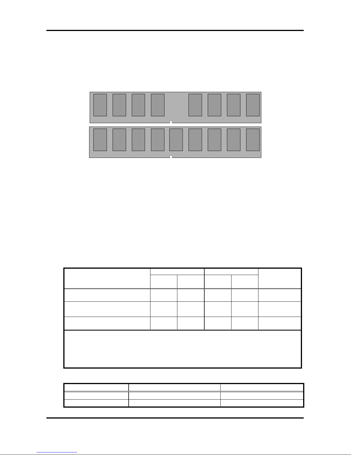
The following diagram shows common types of memory modules.
DDR Unbuffered ECC
DDR Unbuffered
Key points to note before installing memory:
• 128MB, 256MB, 512MB and 1GB unbuffered non-ECC PC2700/PC3200
DDR
memory modules are supported
• All installed memory will be automatically detected and no jumpers or settings need
changing.
• The Tomcat i915 S5120 supports up to 4GB of memory
• Registered Memory is NOT supported.
• You can install either single or double-sided modules on this motherboard. Each
DIMM can work in single-channel mode or dual-channel mode. Please note that
memory modules of the same type and density are required while using dualchannel DDR. Mismatched memory may cause system instability.
Refer to the following table for details of dual-channel DDR.
Channel A Channel B
Dual-Channel Mode
DIMM1
(Blue)
DIMM2
(Black)
DIMM3
(Blue)
DIMM4
(Black)
System
Density
Two DIMM Symmetrical
Population
9 9 256MB~2GB
Two DIMM Symmetrical
Population
9 9 256MB~2GB
Four DIMM Symmetrical
Population
9 9 9 9 512MB~4GB
Note
1. 9: Installing128MB~1GB Memory modules
2. Symmetrical DIMMs must be identical
- Same DRAM Technology, eg 128M-bit, 256-bit, etc.
- Same DRAM bus width, eg x8 or x16
- Matched Sided DIMMs (Single Sided or Double Sided)
• Supported System Bus Frequency and Memory Speed Combinations
CPU FSB DDR DIMM Type Memory Frequency
800MHz PC3200, PC2700 400, 333MHz
533MHz PC2700 333MHz
Tomcat i915 S5120 Chapter 2: Board Installation
2-15
http://www.tyan.com
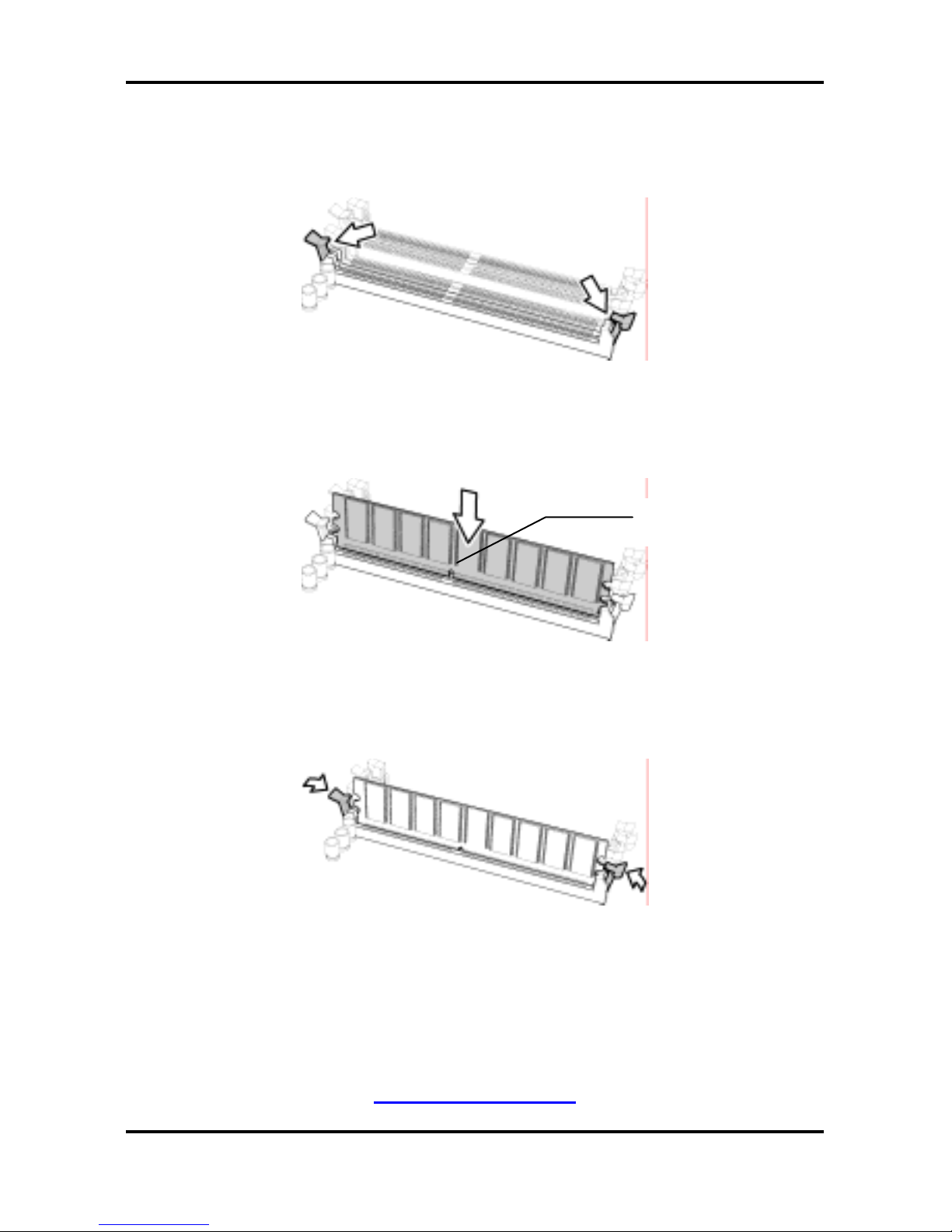
2.7.1 Memory Installation Procedure
Follow these instructions to install memory modules into the Tomcat i915 S5120.
1. Press the locking levers in the direction shown in the following illustration.
2. Align the memory module with the socket. The memory module is keyed to fit only one
way in the socket.
3. Seat the module firmly into the socket by gently pressing down until it sits flush with the
socket. The locking levers pop up into place.
2.8 Installing the Processor and Cooling Fan
Your Tomcat i915 S5120 supports the latest processor technologies from Intel. Check the
TYAN website for latest processor support:
http://www.tyan.com
Key slot
Tomcat i915 S5120 Chapter 2: Board Installation
2-16
http://www.tyan.com
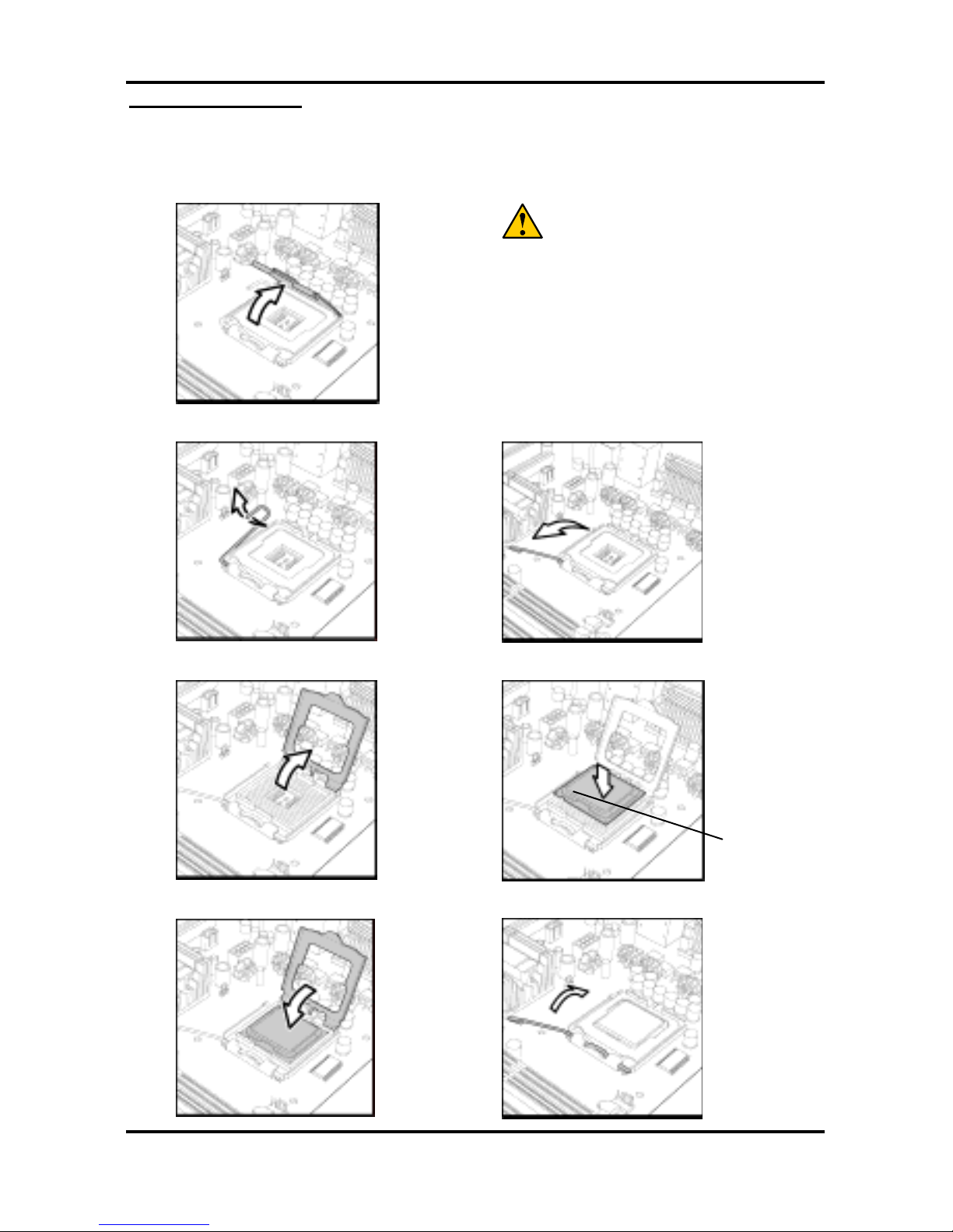
Processor Installation
The processor should be installed carefully. Make sure you are wearing an antistatic
strap and handle the processor as little as possible.
Follow these instructions to install your processor
1. Locate the processor socket on the motherboard and lift the protective cover off as
shown.
WARNING:
This new processor socket designed by
Intel is easy to be damaged. The processor
has to be installed very carefully to prevent
the contact pins of the socket from
breaking. It is strongly recommended the
processor installation job to be handled by
the experienced technician.
2. Pull the locking lever out of its locked position and let it spring into the open position.
3. Lift the metal cover to expose the socket interior and place the processor in as shown.
4. Close the cover and return the locking lever to its locked position.
Tomcat i915 S5120 Chapter 2: Board Installation
2-17
http://www.tyan.com
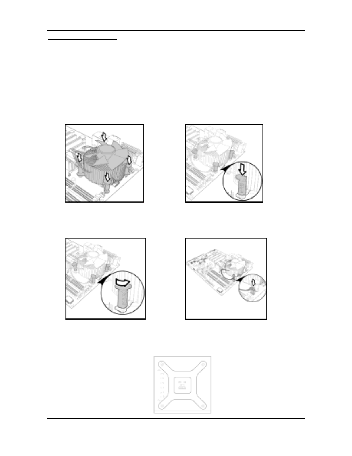
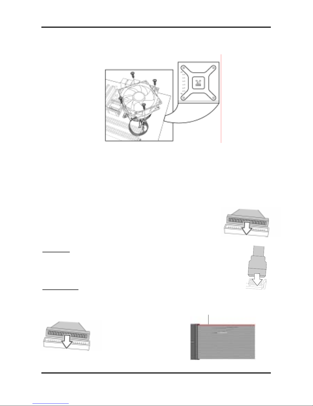
Cooling Fan Installation
After you have installed the processor, the heatsink should be installed to ensure that the
processor runs efficiently and does not overheat. Use the heatsink supplied for best results.
Follow these instructions to install the heatsink shown.
1. Apply some thermal compound (also called heatsink compound or thermal grease) to
the top of the processor. Try and apply a thin, even layer over the top of the processor.
2. Align the heatsink with the four holes around the processor socket.
3. Press the heatsink down until the four white, plastic pegs are securely seated in the
holes.
4. Press down the black pegs until they click to lock the heatsink in place.
To remove the heatsink you will need to twist each of the black locking pegs until they spring
up and unlock the heatsink from the motherboard.
Remember to connect the power supply for the fan to complete the installation.
Some heat sinks require a bracket to be installed beneath the motherboard before the heat
sink is placed on the top side of the motherboard. To install a heat sink like this:
1 Turn the motherboard upside down and place the rear bracket in position with the
mounting posts poking through the corresponding holes in the motherboard.
Tomcat i915 S5120 Chapter 2: Board Installation
2-18
http://www.tyan.com
2 Turn the motherboard the right way up, holding the bracket in place.
3 Place the heat sink assembly on top of the processor.
It should match up with the mounting holes on the rear bracket.
4 Screw the heat sink assembly into place.
If there is a fan on the heat sink you will need to connect the power lead for the fan to one of
the fan power supply pin headers on the motherboard.
2.9 Installing Drive Cables
IDE and FDD connectors are “keyed” to only allow insertion only one way. TYAN
motherboards have two on-board IDE channels, each supporting two drives. The black
connector is a standard IDE channel. Only the blue connector
supports RAID.
Insert the IDE cable as shown in the diagram.
TIP: When connecting to an IDE cable to a drive, Pin 1 on the IDE
cable (usually designated by a colored wire) should be closest to the
drive power connector.
Ser ial ATA
Attaching Serial ATA cables to the Serial ATA connectors is illustrated below:
Plug in one end of the Serial ATA cable into the motherboard Serial ATA
connector, and the other end into the drive. Each standard Serial ATA cable has
two connectors, one at each end. Connectors are the same on both ends.
Floppy Drives
Floppy disk drive (FDD) cables can be installed in the same way as IDE cables. Usually
connectors are keyed to prevent insertion the wrong way. In most cases the cable should be
inserted into the drive with pin 1 closest to the power input. FDD cables usually have a single
red wire that marks pin 1. See the diagram below.
Colored cable denotes pin 1
Tomcat i915 S5120 Chapter 2: Board Installation
2-19
http://www.tyan.com
Troubleshooting Floppy Drives
See the chart below for troubleshooting floppy disk drive installations.
Symptoms of incorrectly installed floppy drives
Drive is not automatically detected
Usually caused by faulty cables, cables put in
backwards or a faulty floppy drive. Try another
floppy drive or try replacing the cable. Check to
see if the onboard floppy controller is enabled in
the BIOS setup.
Drive Fail message at boot up
The cable, floppy drive or motherboard may be
faulty. Try another drive or cable.
Drive does not power on
Check power cable and cabling. A faulty power
supply or drive cable could be the problem.
Drive activity light is constantly on
Usually signifies that the cable on the drive is
inserted backwards. Reverse the cable at the
floppy drive end and try again.
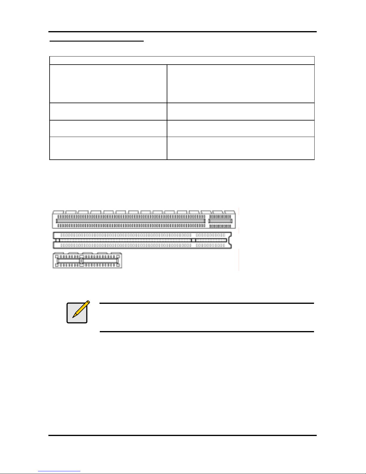
2.10 Installing Expansion Cards
Before installing add-in cards, you should ensure that they are fully compatible with your
motherboard. For this reason, we’ve provided the diagrams below, showing the expansion
slots that appear on your motherboard.
Expansion cards should be pushed firmly into the appropriate slot. Excessive force can
damage both the card and the motherboard and care should be taken.
Notes
Unplug the power connector to the motherboard before performing
system hardware changes, to avoid damaging the board or expansion
cards
PCI Slot
X16 PCI Express Slot
X1 PCI Express Slot
Tomcat i915 S5120 Chapter 2: Board Installation
2-20
http://www.tyan.com
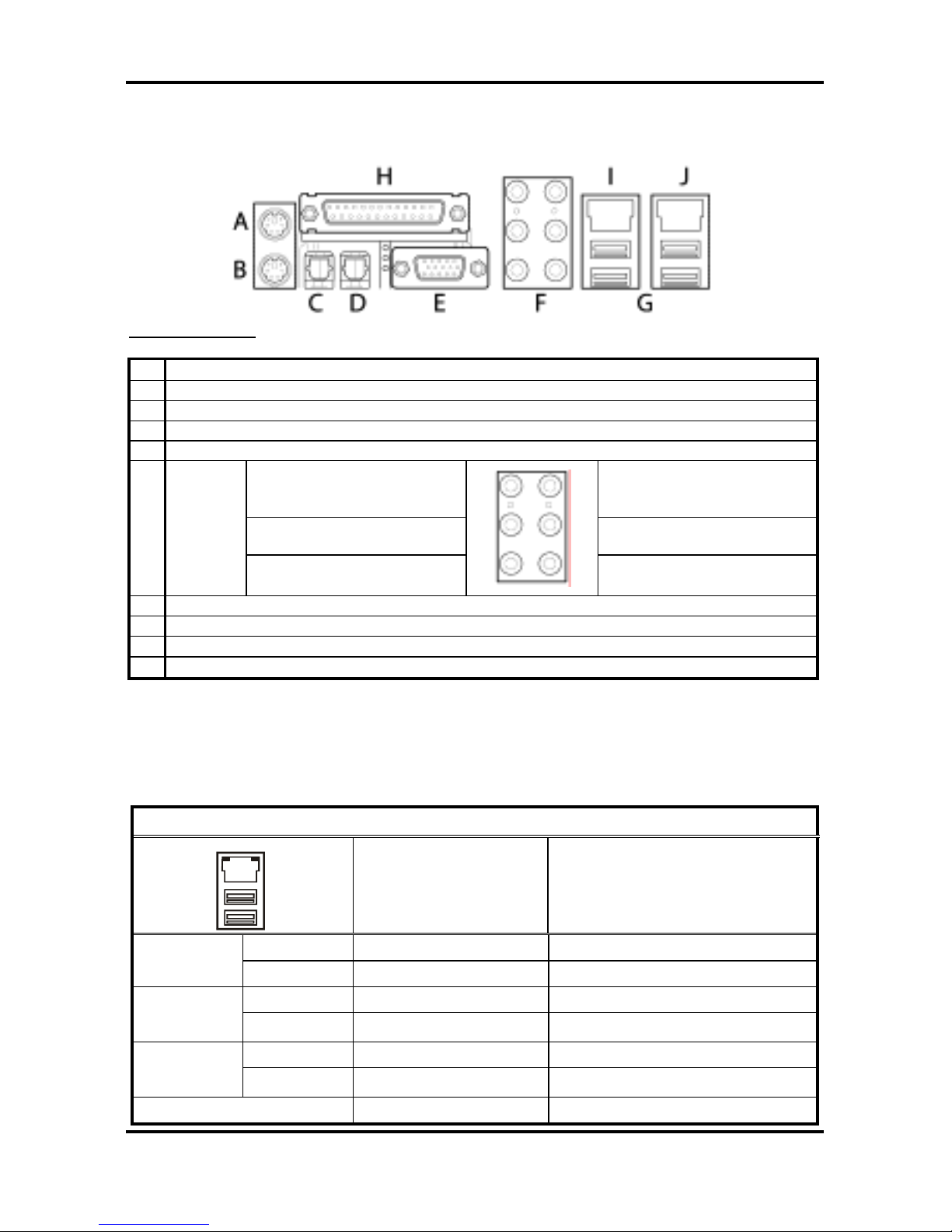
2.11 Connecting External Devices
Your new motherboard supports a number of different interfaces for connecting peripherals.
See the diagram below.
Port definitions:
A PS2 mouse port (green)
B PS2 keyboard port (purple)
C SPDIF-IN port (red)
D SPDIF-OUT port (light green)
E VGA port (blue)
Center / subwoofer
speaker (orange)
Line–in (blue)
Rear speaker (black) Front speaker (light green)
F
5 + 1
audio
out
ports
Side speaker (grey)
Mic-in (pink)
G USB 2.0 ports
H Parallel printer port (dark red)
I 10/100 Ethernet port
J Gigabit Ethernet port
Peripheral devices can be plugged straight into any of these ports but software may be
required to complete the installation
2.11.1 Onboard LAN LED Color Definition
The two onboard Ethernet ports have green and yellow LEDs to indicate LAN status. The
chart below illustrates the different LED states.
LAN Link/Activity LED Scheme
Right
Left
Left LED Right LED
Link Green Off
10 Mbps
Active Blinking Green Off
Link Green Green
100 Mbps
Active Blinking Green Green
Link Green Yellow
1000 Mbps
Active Blinking Green Yellow
No Link Off Off
Tomcat i915 S5120 Chapter 2: Board Installation
2-21
http://www.tyan.com
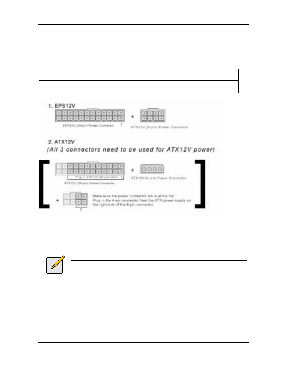
2.12 Installing the Power Supply
There are three power connectors on your Tomcat i915 S5120. By default, the Tomcat
i915 S5120 requires that you have an EPS12V power supply that has a 24-pin and an 8-pin
power connector. However, the Tomcat i915 S5120 is also ATX12V compatible. All 3 power
connectors need to be used if you plan on using the ATX12V power.
Power Supply
Main
power connector
12V
power connector
4-pin AUX
power connector
EPS12V Required Required Not required
ATX12V Required Required Required
1. Disconnect power supply from electrical outlet
2. Connect 12V power connector
3. Connect 4-pin AUX power connector (required for ATX12V power)
4. Connect Main power connector
5. Connect power cable to power supply to power outlet
Note
YOU MUST unplug the power supply before plugging the power cables to
motherboard connectors.
2.13 Finishing Up
Before closing up your chassis, make sure that all cables and wires are connected properly,
especially IDE cables and most importantly, jumpers. You may have difficulty powering on
your system if the motherboard jumpers are not set correctly.
If you experience difficulty, you can find help by asking your vendor for assistance. If they are
not available for assistance, please find setup information and documentation online at our
website (www.tyan.com) or by calling your vendor’s support line.
Tomcat i915 S5120 Chapter 3: BIOS Setup
3-1
http://www.tyan.com
Chapter 3: BIOS Setup
3.1 About the BIOS
The BIOS is the basic input/output system, the firmware on the motherboard that enables your
hardware to interface with your software. This chapter describes different settings for the
BIOS that can be used to configure your system.
The BIOS section of this manual is subject to change without notice and is provided for
reference purposes only. The settings and configurations of the BIOS are current at the time of
print, and therefore may not match exactly what is displayed on screen.
This section describes the BIOS setup program. The setup program lets you modify basic
configuration settings. The settings are then stored in a dedicated, battery-backed memory
(called NVRAM) that retains the information when the power is turned off.
This motherboard’s BIOS is a customized version of the industry-standard BIOS for IBM PC
AT-compatible personal computers. The BIOS provides critical, low-level support for the
system’s central processing unit (CPU), memory, and I/O subsystems.
This BIOS has been customized by adding important features such as virus and password
protection, power management, and chipset “tuning” features that control the system. This
section will guide you through the process of configuring the BIOS for your system setup.
3.1.1 Starting Setup
The BIOS is immediately activated when you turn on the computer. The BIOS reads system
configuration in CMOS RAM and begins the process of checking out the system and
configuring it through the Power-On-Self-Test (POST).
When these preliminary tests are complete, the BIOS searches for an operating system on
one of the system’s data storage devices (hard drive, CD-ROM, etc). If one is found, the BIOS
will launch that operating system and hand control over to it. You can enter the BIOS setup by
pressing the [Delete] key when the machine boots up and begins to show the memory count.
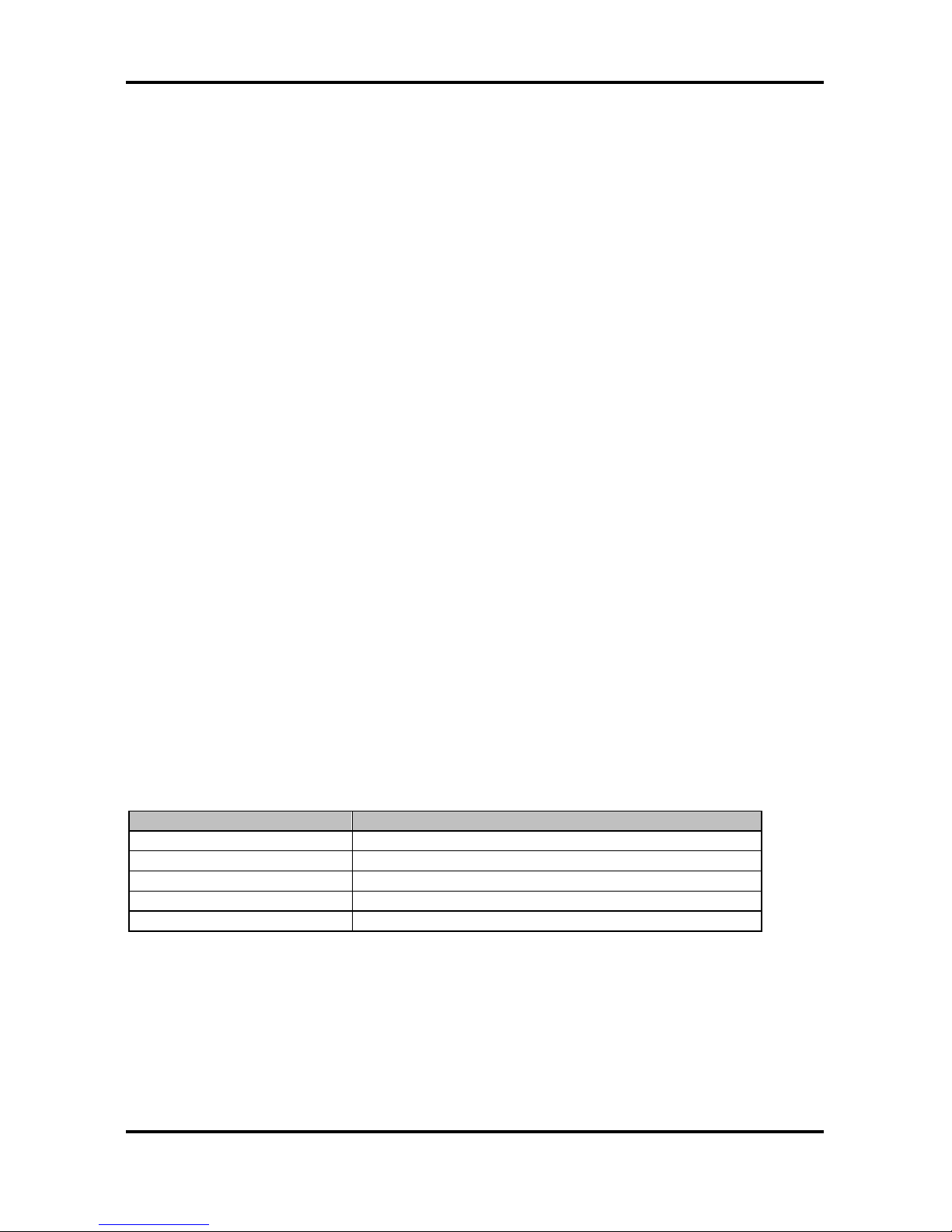
3.1.2 Setup Basics
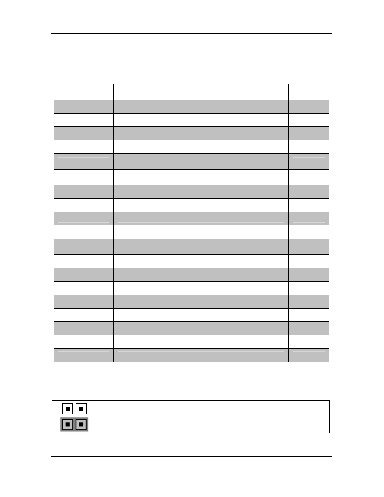
The table below shows how to navigate in the setup program using the keyboard.
Key Function
Tab Moves from one selection to the next
Left/Right Arrow Keys Changes from one menu to the next
Up/Down Arrow Keys Moves between selections
Enter Opens highlighted section
PgUp/PgDn Keys Changes settings.
3.1.3 Getting Help
Pressing [F1] displays a small help window that describes the appropriate keys to use and the
possible selections for the highlighted item. To exit the Help Window, press [ESC] or the [F1]
key again.
Tomcat i915 S5120 Chapter 3: BIOS Setup
3-2
http://www.tyan.com
3.1.4 In Case of Problems
If you have trouble booting the computer after making and saving changes with the BIOS
setup program, restart the computer by holding the power button down until the computer
shuts off (usually within 4 seconds); resetting by pressing CTRL-ALT-DEL; or clearing the
CMOS.
Only alter settings that you thoroughly understand. In particular, do not change settings in the
Chipset section unless you are sure of the outcome. TYAN or your system manufacturer has
carefully chosen the chipset defaults for best performance and reliability. Even a small change
to the Chipset setup options may cause the system to become unstable or unusable.
3.1.5 Setup Variations
While the basic look and function of the BIOS setup remains more or less the same for most
systems, the appearance of your Setup screen may differ from the charts shown in this section.
Each system design and chipset combination requires a custom configuration. In addition, the
final appearance of the Setup program depends on the system designer. Your system
designer may decide that certain items should not be available for user configuration, and
remove them from the BIOS setup program.
Note
On the following pages, options written in bold type represent the BIOS
Setup default.
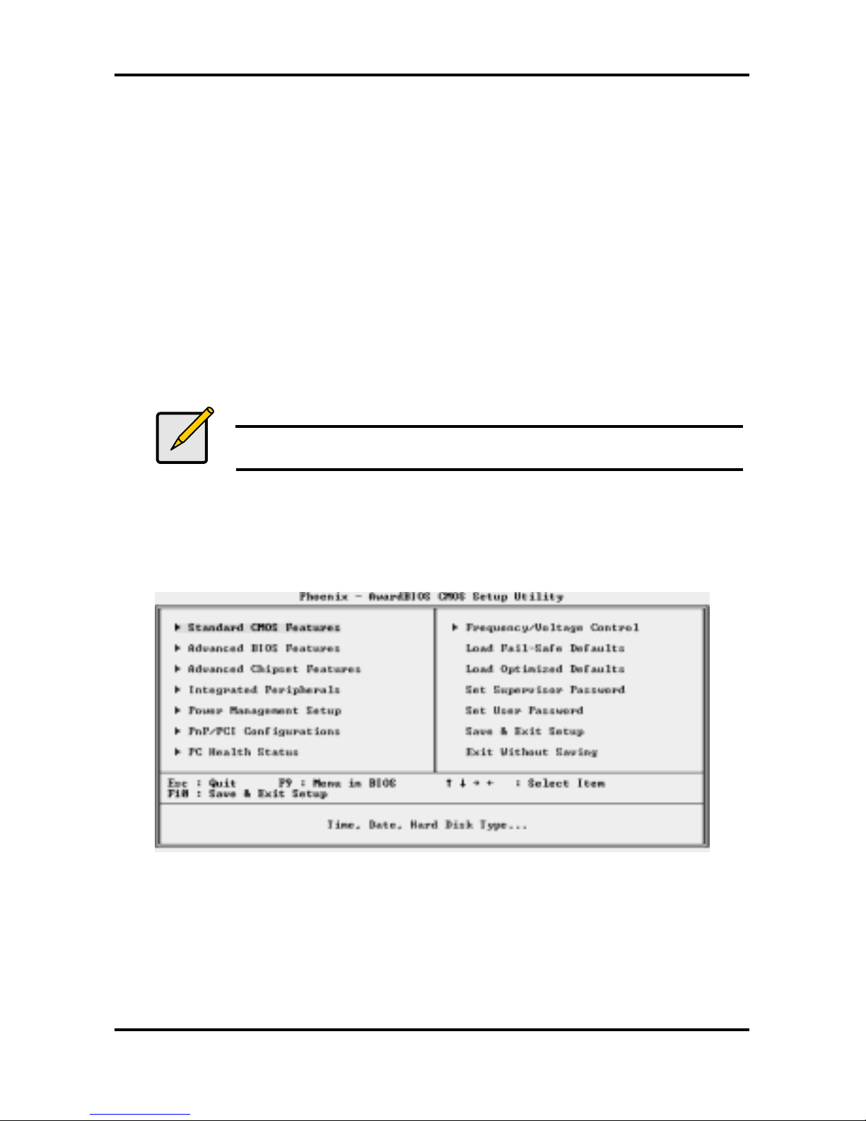
3.2 Main BIOS Setup
When you enter Phoenix - AwardBIOS CMOS Setup Utility, the following screen will appear as
below:
Standard CMOS Features
Use this menu for basic system configuration.
Advanced BIOS Features
Use this menu to set the Advanced Features available on your system.
Advanced Chipset Features
Use this menu to change the values in the chipset registers and optimize your system's
performance.

Tomcat i915 S5120 Chapter 3: BIOS Setup
3-3
http://www.tyan.com
Integrated Peripherals
Use this menu to specify your settings for integrated peripherals.
Power Management Setup
Use this menu to specify your settings for power management.
PnP
/ PCI Configuration
This entry appears if your system supports PnP / PCI.
PC Health Status
Use this menu to show your system temperature, speed and voltage status.
Frequency/Voltage Control
Use this menu to specify your settings for frequency/voltage control.
Load Fail-Safe Defaults
Use this menu to load the BIOS default values for the minimal/stable performance for your
system to operate.
Load Optimized Defaults
Use this menu to load the BIOS default values that are factory settings for optimal
performance system operations. While Award has designed the custom BIOS to maximize
performance, the factory has the right to change these defaults to meet their needs.
Supervisor / User Password
Use this menu to set User and Supervisor Passwords.
Save & Exit Setup
Save CMOS value changes to CMOS and exit setup.
Exit Without Saving
Abandon all CMOS value changes and exit setup.
 Loading...