

TYAN Tomcat i875PF S5105, S5105 User Manual

Tomcat i875PF S5105 User’s Manual
i
http://www.tyan.com
Tomcat i875PF
///
S5105
Revision 1.00
Copyright © TYAN Computer Corporation, 2003. All rights reserved. No part of this manual
may be reproduced or translated without prior written consent from TYAN Computer Corp.
All registered and unregistered trademarks and company names contained in this manual are
property of their respective owners including, but not limited to the following.
TYAN, Tomcat, i875PF and S5105 are trademarks of TYAN Computer Corporation.
Intel, Pentium 4, and combinations thereof are trademarks of Intel Corporation.
Award, AwardBIOS are trademarks of Award Software Incorporated.
Microsoft and Windows are trademarks of Microsoft Corporation.
IBM, PC, AT and PS/2 are trademarks of IBM Corporation.
ATI, ATI RAGE is a trademark of ATI Technologies Incorporated.
Winbond is a trademark of Winbond Electronics Corporation.
Portable Document Format (PDF) is a trademark of Adobe Corporation.
Information contained in this document is furnished by TYAN Computer Corporation and has
been reviewed for accuracy and reliability prior to printing. TYAN assumes no liability
whatsoever, and disclaims any express or implied warranty, relating to sale and/or use of
TYAN products including liability or warranties relating to fitness for a particular purpose or
merchantability. TYAN retains the right to make changes to product descriptions and/or
specifications at any time, without notice. In no event will TYAN be held liable for any direct or
indirect, incidental or consequential damage, loss of use, loss of data or other malady resulting
from errors or inaccuracies of information contained in this document.

Tomcat i875PF S5105 Table of Contents
ii
http://www.tyan.com
Table of Contents
Before you begin… ................................................................................................................. iii
Chapter 1: Introduction............................................................................................................ 1
1.1 – Congratulations! ......................................................................................................... 1
1.2 – Hardware Specifications ............................................................................................ 1
Chapter 2: Board Installation .................................................................................................. 3
2.1 – Board Parts ................................................................................................................ 4
2.2 – Block Diagram............................................................................................................ 5
2.3 – Jumper and Connector Settings ................................................................................ 6
2.4 – Mounting the Motherboard ....................................................................................... 13
2.5 – Installing the Memory............................................................................................... 14
2.6 – Memory Installation Procedure ................................................................................ 15
2.7 – Installing the Processor and Heatsink...................................................................... 16
2.8 – Attaching Drive Cables ............................................................................................ 18
2.9 – Installing Add-In Cards............................................................................................. 20
2.10 – Connecting External Devices................................................................................. 21
2.11 – Installing the Power Supply.................................................................................... 21
2.12 – Finishing Up ........................................................................................................... 22
Chapter 3: BIOS Setup...........................................................................................................23
3.1 – Main BIOS Setup ..................................................................................................... 25
3.2 – Standard CMOS Features ....................................................................................... 26
3.3 – Advanced BIOS Features ........................................................................................ 28
3.4 – Advanced Chipsets Features................................................................................... 31
3.5 – Integrated Peripherals.............................................................................................. 32
3.6 – Power Management Setup ...................................................................................... 37
3.7 – PnP/PCI Configurations ........................................................................................... 41
3.8 – PC Health Status ..................................................................................................... 42
3.9 – Frequency/Voltage Control ...................................................................................... 43
3.10 – Load Fail-Safe Defaults ......................................................................................... 44
3.11 – Load Optimized Defaults........................................................................................ 44
3.12 – Supervisor/User Password Setting ........................................................................ 45
3.13 – Exit Selecting ......................................................................................................... 46
Chapter 4: SATA/RAID Setup ................................................................................................ 48
4.1 BIOS Configuration ..................................................................................................... 48
4.2 Installing Serial ATA (SATA) hard disks ..................................................................... 48
4.3 Creating, Deleting, and Resetting RAID Volumes ...................................................... 49
4.4 Create RAID 0 or RAID 1 Volume............................................................................... 50
4.5 Delete RAID Volume................................................................................................... 51
4.6 Reset Disks to Non-RAID ........................................................................................... 52
4.7 Pre-Installation of the Intel® RAID Driver ................................................................... 53
4.8 Using the Intel® Application Accelerator RAID Edition Utility ..................................... 54
4.8.1 Installing the Intel® Application Accelerator RAID Edition ....................................... 54
4.8.2 RAID Migration Instructions ..................................................................................... 54
4.8.3 Uninstalling the Intel® Application Accelerator RAID Edition................................... 60
Chapter 5: Diagnostics ..........................................................................................................62
5.1 Beep Codes ................................................................................................................ 62
5.2 Flash Utility.................................................................................................................. 62
Appendix I: Glossary ............................................................................................................. 63
Appendix II: Post Error Code for BIOS ................................................................................ 69
Appendix III: SMDC Information ........................................................................................... 74
Technical Support ............................................................................................................. 75
Tomcat i875PF S5105 Before you begin…
iii
http://www.tyan.com
Before you begin…
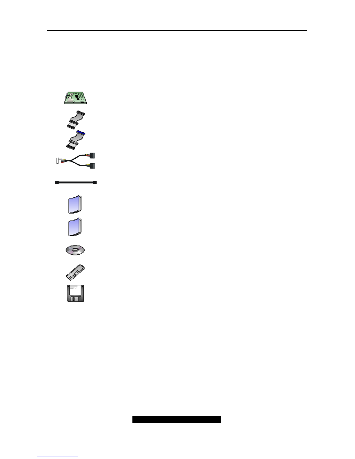
Check the box contents!
The retail motherboard package should contain the following:
1x Tomcat i875PF S5105 motherboard
1x 34-Pin floppy drive cable
1x Ultra-DMA-133/100/66/33 IDE cable
1 x Serial ATA power cable
2 x Serial ATA cable
1x Tomcat i875PF S5105 User’s Manual
1x Tomcat i875PF S5105 Quick Reference Guide
1x TYAN driver CD
1x I/O shield
1 x Serial ATA driver diskette
If any of these items are missing, please contact your vendor/dealer for replacement before
continuing with the installation process.

Tomcat i875PF S5105 Chapter 1: Introduction
1
http://www.tyan.com
Chapter 1: Introduction
1.1 – Congratulations!
You have purchased one of the most powerful solutions for the Intel® Pentium
4 processor,
the Tomcat i875PF S5105 Based on Intel® 875P chipset, this platform offers convenient
remote Intelligent Platform Management Interface (IPMI) monitoring through a Server
Management Daughter Card. The Tomcat i875PF S5105 are Flex ATX form factor, onboard
dual Gigabit Ethernet port, Serial ATA, and an onboard ATI 8MB PCI RAGE XL VGA.
Remember to visit TYAN’s Website at http://www.tyan.com
. There you can find information on
all of TYAN’s products with FAQs, distributors list, and BIOS setting explanations.
1.2 – Hardware Specifications
PROCESSOR
Socket 478
Intel® Pentium 4 Processors,
“Northwood/Prescott”
On-board VRM 10.0
800/533/400 MHz System Bus support
CHIPSET
Intel® 875P chipset
MCH + ICH5R
Winbond W83627HF Super I/O chip
EXPANSION SLOTS
Total two 32-bit/33MHz PCI v2.2 slots
MEMORY
Dual Channel Memory Bus
Four DDR DIMM slots
DDR 266/333/400 supported
Max. 4 GB with Unbuffered DDR
Supports non-ECC/ECC type memory
modules
Registered RAM not supported
INTEGRATED LAN
Intel® 82547 CSA 10/100/1000 controller
Intel® 82540/82541 PCI 10/100/1000
controller
WOL/PXE/ASF2.0 support
Two RJ-45 LAN connectors w/ LEDs
INTEGRATED PCI GRAPHICS
ATI RageTM XL PCI graphics
controller
8MB Frame Buffer of video memory
BIOS
Award BIOS on 4Mb Flash (FWH)
ACP1.1/APM1.2
User settings of HW monitoring
Auto configuration of IDE hard disk
types
Quick boot and multiple boot options
LAN remote boot (PXE) support
Event Log support (4K EEPROM)
Power Management: S1, S3, S4 and
S5
SYSTEM MANAGEMENT
W83627HF HW monitoring
One 3-pin CPU fan header with
temperature controlled
Two 3-pin chassis fan headers with
temperature controlled
2-pin Chassis Intrusion header
Two temperature sensors and voltage
monitoring
Watchdog timer
Supports Tyan Server Management
Daughter card (SMDC*) via Tyandefined header

Tomcat i875PF S5105 Chapter 1: Introduction
2
http://www.tyan.com
INTEGRATED I/O
One Floppy connector for up to two drives
Two 9-pin UART Serial ports (one header
via cable)
Four USB 2.0 Ports (2 rear ports and 2
headers)
PS/2 Mouse & Keyboard ports
INTEGRATED PCI ATA AND SATA
Intel® ICH-5 or ICH-5R
Up to four Enhanced UDMA and SATA
devices
Dual channel UDMA Master mode for up
to 4 devices
− Supports for UDMA 33/66/100 IDE
drives and ATAPI compliant devices
Support two independent SATA ports
− Data transfer at 1.5 Gb/s
− Supports RAID 0 or 1
FORM FACTOR
Flex ATX (9.0” x 8.0”)
ATX12V power connectors
Side by side PS2 Mouse/Keyboard
connectors
Stacked 2 USB connectors and RJ45
LAN connector w/LEDs
One Serial connector
One VGA connector
One RJ45 LAN connectors w/ LEDs
REGULATORY
FCC Class B (Declaration of
Conformity)
CE (Declaration of Conformity)
* Tyan SMDC is a System Management
Daughter Card. It enables you to access
the hardware remotely and perform
monitor, control, and diagnose activities
effectively.
See Appendix III (Pg 75) for details In
Tyan SMDC.
Software Specifications
OS (Operating System) Support
Microsoft Windows Server 2000
Microsoft Windows Advanced Server 2000
Microsoft Windows XP
Microsoft Windows Server 2003
Red Hat 8.0, 9.0
FreeBSD5.1
Solaris 9.0
Other distributions of Linux pending validation
Note: TYAN reserves the right to add support or discontinue support for any OS with or
without notice.

Tomcat i875PF S5105 Chapter 2: Board Installation
3
http://www.tyan.com
Chapter 2: Board Installation
Installation
You are now ready to install your motherboard. The mounting holes pattern of the Tomcat
i875PF S5105 matches the Flex ATX specification. Before continuing with installation, confirm
that your chassis supports a standard Flex ATX motherboard.
How to install our products right…. the first time!
The first thing you should do read this user’s manual. It contains important information that
will make configuration and setup much easier. Here are some precautions you should take
when installing your motherboard:
(1) Ground yourself properly before removing your motherboard from the antistatic bag.
Unplug the power from your computer power supply and then touch a safely
grounded object to release static charge (i.e. power supply case). For the safest
conditions, TYAN recommends wearing a static safety wrist strap.
(2) Hold the motherboard by its edges and do not touch the bottom of the board, or flex
the board in any way.
(3) Avoid touching the motherboard components, IC chips, connectors, memory
modules and leads.
(4) Place the motherboard on a grounded antistatic surface or on the antistatic bag that
the board was shipped in.
(5) Inspect the board for damage.
The following pages include details on how to install your motherboard into your chassis, as
well as installing the processor, memory, disk drives and cables.
Note: DO NOT APPLY POWER TO THE BOARD IF IT HAS BEEN DAMAGED
Tomcat i875PF S5105 Chapter 2: Board Installation
4
http://www.tyan.com
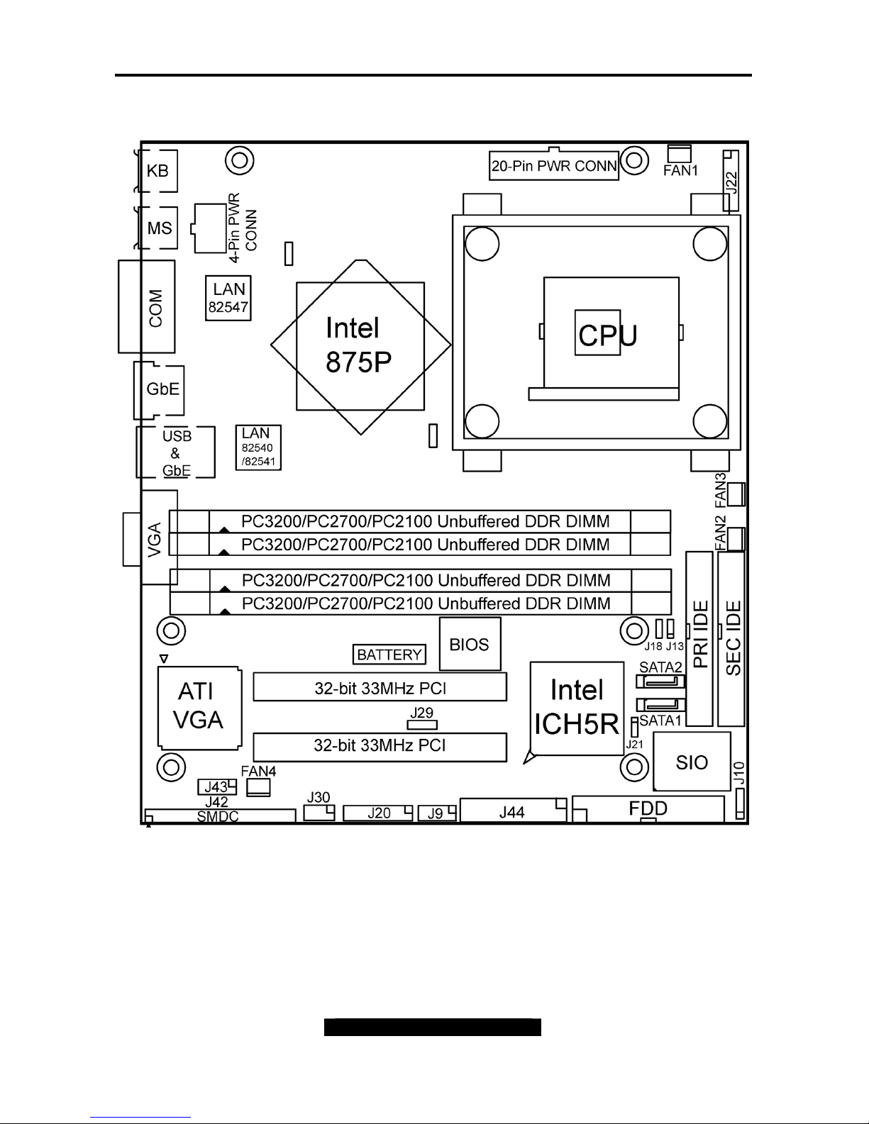
2.1 – Board Parts
This jumper diagram is representative of the latest board revision available at the time
of publishing. The board you receive may or may not look exactly like the above
diagram. The board parts are not to scale.
Tomcat i875PF S5105 Chapter 2: Board Installation
5
http://www.tyan.com
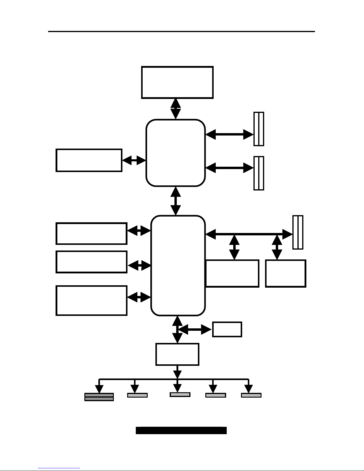
2.2 – Block Diagram
The following is a block diagram of the Tomcat i875PF S5105.
PS/2
KBD & MS
800/533/400 MHz FSB
FDD
Port
Serial
Port
Serial
Port
2 PCI Slots
PCI BUS
266
MB/S
ECC / Non-ECC
DDR 266 / 333 / 400
Memory
LPC
Su
p
er I/O
2 x ATA
100/66/33
Ports
USB 2.0
2 Ports and 2
front Headers
Gigabit LAN
Intel
82540/82541
ATI
Rage XL
Intel
82801ER
ICH5-R
2 x SATA Ports
150MB/S
mPGA478 Socket
for Prescott or
Northwood CPU
Intel 82875P
MCH
CSA Gigabit LAN
Intel 82547
BIOS
Parallel
Port
Tomcat i875PF S5105 Chapter 2: Board Installation
6
http://www.tyan.com
2.3 – Jumper and Connector Settings
Jumper or Connector Functions Ref. Page
J9 Front USB Header Page 7
J10 External Speaker Header Page 7
J13 SATA LED Header Page 8
J18 CMOS Reset Page 8
J20 Front Panel Connector Page 9
J21 Chassis Intrusion Header Page 9
J42 SMDC Connector Page 10
J43 Serial Port Internal Header Page 10
J44 Parallel Port Internal Header N/A
FAN1 ~ FAN4 Fan Connectors Page 11
SATA1 ~ SATA2 SATA Connectors Page 11
LAN1 Intel® 82547 GbE connector Page 12
LAN2 Intel® 82540/82541 GbE connector Page 12
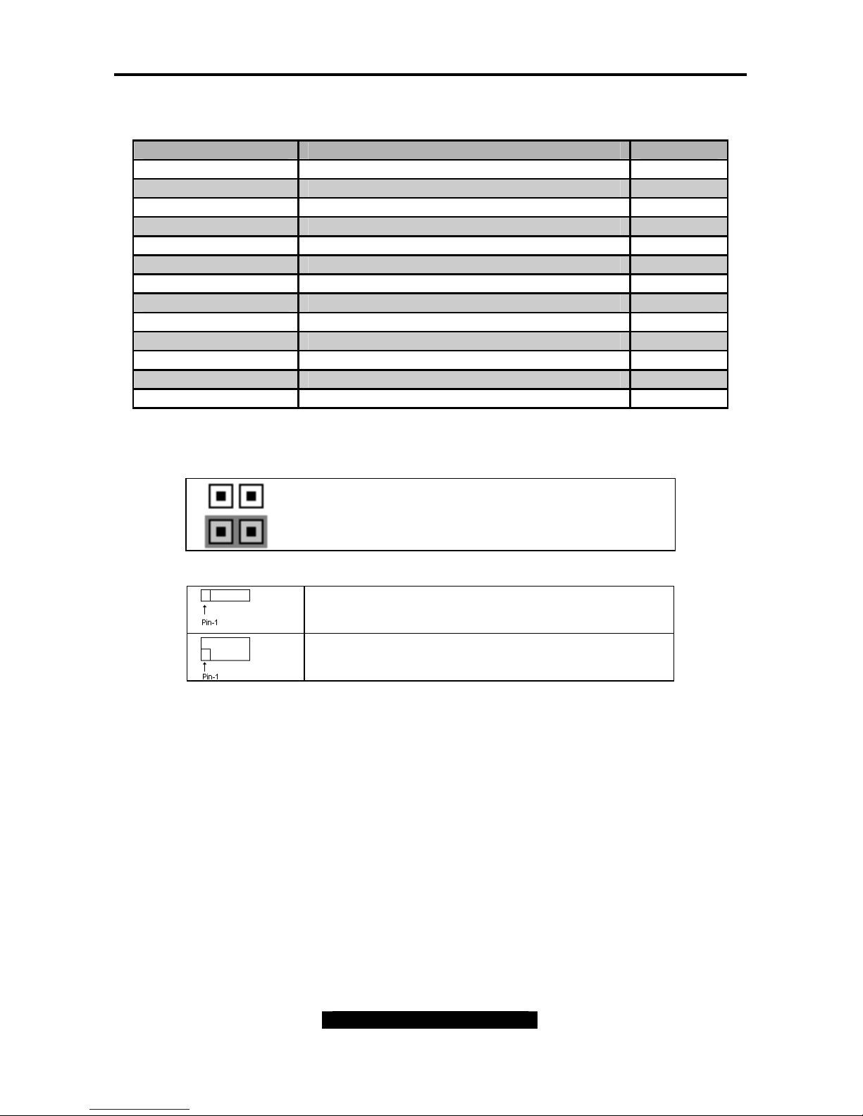
Jumper Legend
Jumper OFF – OPEN (without jumper cap)
Jumper ON – CLOSED (with jumper cap)
To indicate the location of pin-1
To indicate the location of pin-1
Tomcat i875PF S5105 Chapter 2: Board Installation
7
http://www.tyan.com
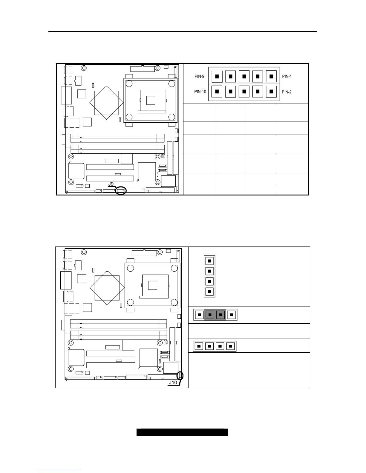
Front USB Header (J9)
Signal
Description
Pin #
Pin #
Signal
Description
VCC 1 2 VCC
USB
Channel_1
Data -
3 4
USB
Channel_2
Data USB
Channel_1
Data +
5 6
USB
Channel_2
Data +
GND 7 8 GND
NC 9 10 GND
External Speaker Header (J10)
Pin_1
Pin_4
Pin_1 : Speaker +
Pin_2 : Buzzer +
Pin_3 : Speaker/ Buzzer –
Pin_4 : Speaker -
Close Pin-2and Pin-3 (Default)
Enable onboard buzzer
Open Pin-1 ~ Pin-4
Disable onboard buzzer and can connect
to chassis 1x4 speaker by Pin_1 and
Pin_4
Tomcat i875PF S5105 Chapter 2: Board Installation
8
http://www.tyan.com
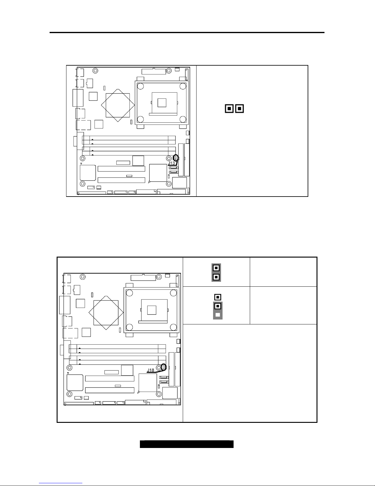
SATA LED Header (J13)
1 2
Pin_1 SATA LED+
Pin_2 GND
CMOS Reset (J18)
Pin_1
Clear COMS
Pin_1
Normal
You can reset the CMOS settings in case an
incorrect setting causes system instability or
you have forgotten your system / setup
password or have just flashed your BIOS by
using these jumpers.
- Power off system, disconnect power supply
from the motherboard
- Set jumper to Clear CMOS
- Wait about 5 seconds
- Set jumper to Normal (Default)
And plug the power supply back into the
motherboard.
Tomcat i875PF S5105 Chapter 2: Board Installation
9
http://www.tyan.com
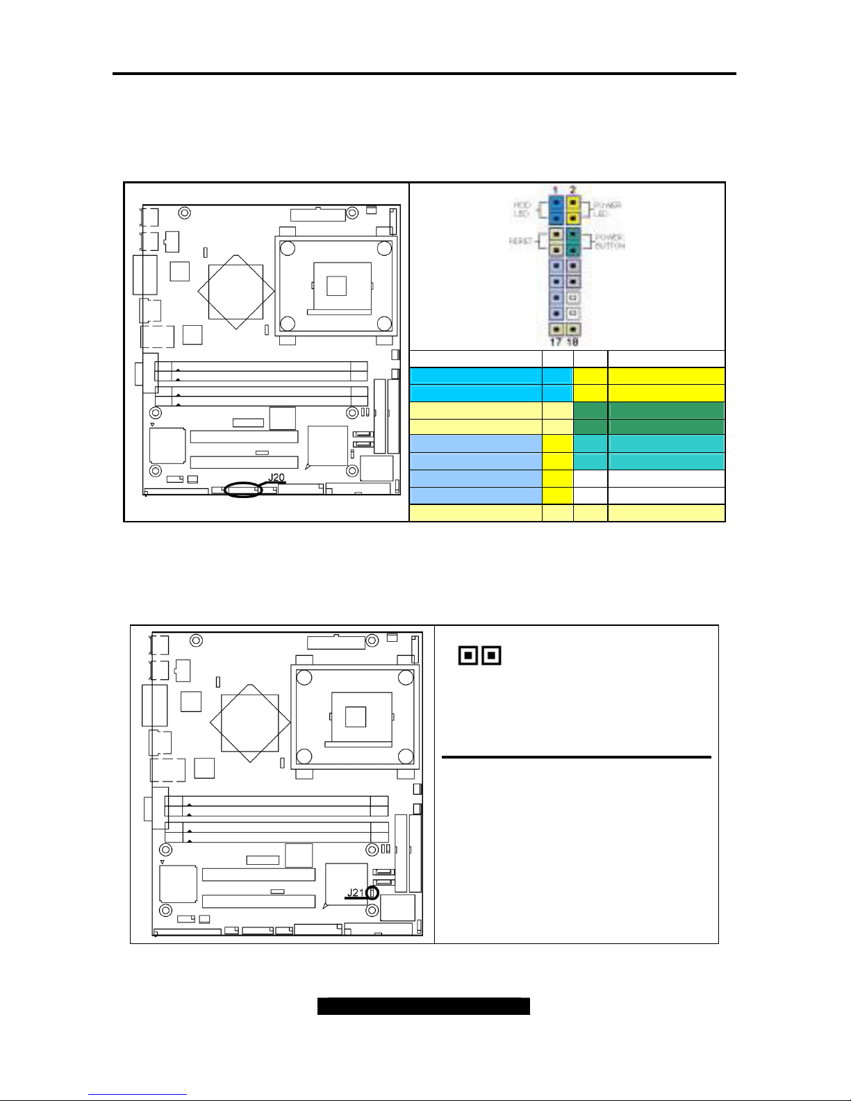
Front Panel Connector (J20)
Your chassis will usually come with connectors to install onto the motherboard, such as HD
and Power LEDs. The Front Panel Connector (J20) has been implemented for such purposes.
Function Pin Pin Function
HDD_LED+ 1 2 PWR_LED+
HDD_LED- 3 4 PWR LED -
Reset Button - 5 6 PWR Button+
Reset Button+ 7 8 PWR Button-
+5V 9
10
NC
IR_RX 11 12 Power
GND 13 14 NC
IR_TX 15 16 NC
Reserved 17 18 Reserved
Chassis Intrusion Header (J21)
1 2
Pin_1 INTRUDER_L
Pin_2 GND
If you would like to protect your
system from outside intrusion, the
detect connector is available for
deployment.
Note: For use with chassis that
support this feature.
Tomcat i875PF S5105 Chapter 2: Board Installation
10
http://www.tyan.com
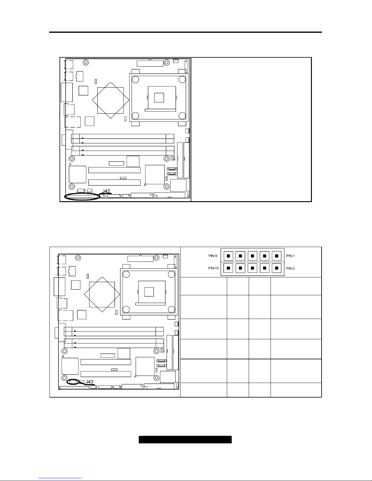
SMDC Connector (J42)
Connect Server Management Daughter
Card (SMDC)
Compatible with Tyan M3289 (SMDC)
See Appendix III for details In Tyan
SMDC
Serial Port Internal Header (J43)
Signal
Description
Pin # Pin #
Signal
Description
DCD
(Data Carrier
Detect)
1 2
DSR (Data-Set-
Ready)
RXD (Receive-
Data)
3 4
RTS (Request-
to-Send)
TXD (Transfer-
Data)
5 6
CTS (Clear-to-
Send)
DTR (Data-
Terminal-
Ready)
7 8
RI (Ring-
Indicator)
GND 9 10 NC
Tomcat i875PF S5105 Chapter 2: Board Installation
11
http://www.tyan.com
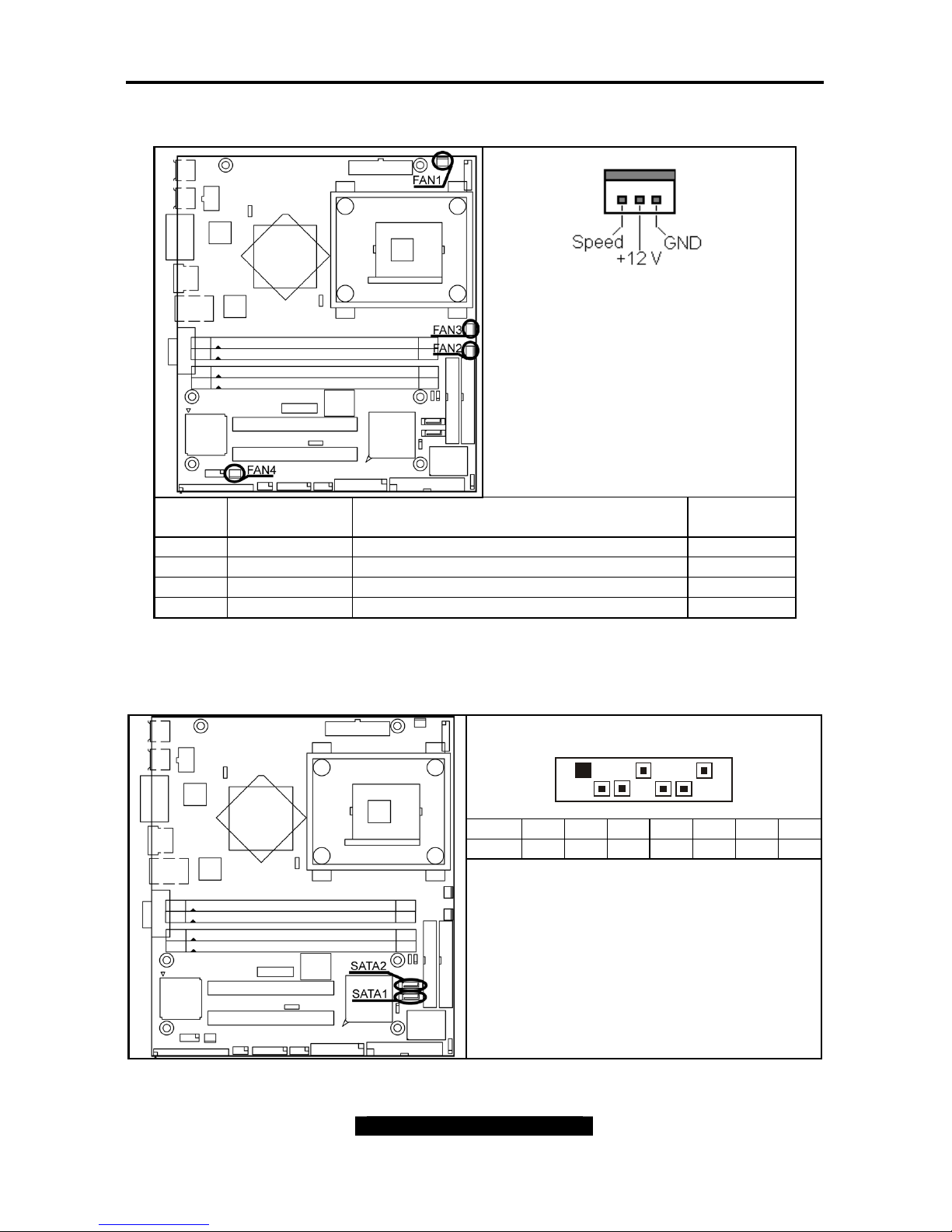
Fan Connectors (FAN 1 & FAN 2 & FAN 3 & FAN 4)
+12V fans supported
Use these connectors to connect cooling
fans, both chassis and processor fans, to
your motherboard. Cooling fans help
keep the system more stable and
operating reliably for its product life.
FAN # Description Functions
Amp Rated
(Maximum)
1 CPU Fan Tachometer/speed Read and controlled 1.5A
2 Chassis Fan Tachometer/speed Read and controlled 1.0A
3 Chassis Fan Tachometer/speed Read and controlled 1.0A
4 Chassis Fan None 0.8A
Serial ATA Connectors (SATA1 & SATA2)
SATA1 / SATA2 (from ICH5-R): Support SATA RAID 0 or 1
1 7
Pin1 234567
Signal GND TXP TXN GND RXN RXP GND
Supports serial ATA devices

Tomcat i875PF S5105 Chapter 2: Board Installation
12
http://www.tyan.com
Onboard LAN LED Color Definition
LAN1---Intel® 82547 GbE NIC activity/link LED information
Left LED Right LED
Network link not established Off Off
Linked at 10 Mbps (10 BaseT)
Activity at 10 Mbps
Off
Off
Green
Blink Green
Linked at 100 Mbps (100 BaseTX)
Activity at 100 Mbps
Yellow
Blink Yellow
Off
Off
Linked at 1000 Mbps (1000 BaseT)
Activity at 1000 Mbps
Yellow
Blink Yellow
Green
Blink Green
LAN2---Intel® 82540/52541 GbE NIC activity/link LED information
Left LED
Right LED
Network link not established Off Off
Linked at 10 Mbps (10 BaseT)
Activity at 10 Mbps
Off
Off
Green
Blink Green
Linked at 100 Mbps (100 BaseTX)
Activity at 100 Mbps
Yellow
Blink Yellow
Off
Off
Linked at 1000 Mbps (1000 BaseT)
Activity at 1000 Mbps
Yellow
Blink Yellow
Green
Blink Green
Tomcat i875PF S5105 Chapter 2: Board Installation
13
http://www.tyan.com
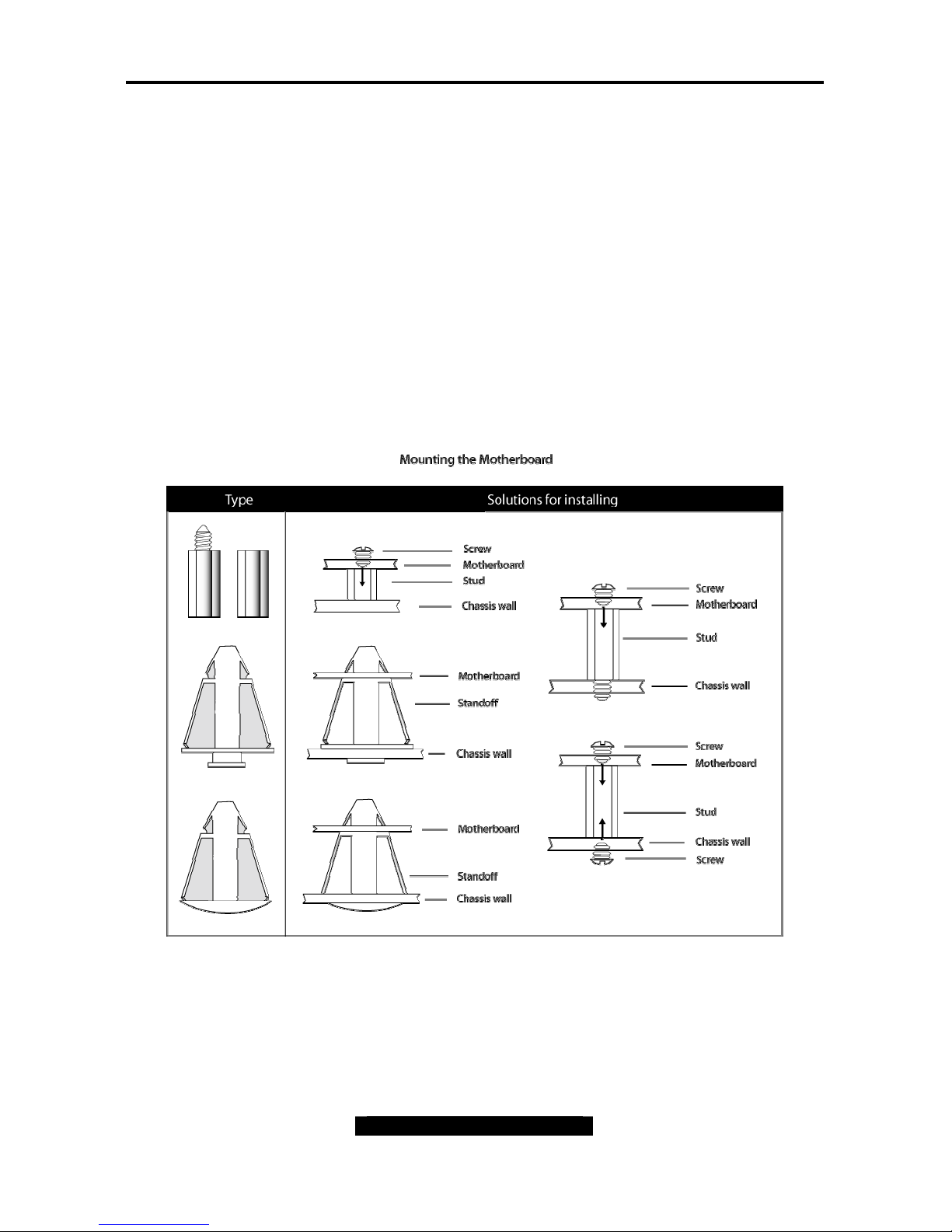
2.4 – Mounting the Motherboard
Before installing your motherboard, make sure your chassis has the necessary motherboard
support studs installed. These studs are usually metal and are gold in color. Usually, the
chassis manufacturer will pre-install the support studs. If you’re unsure of stud placement,
simply lay the motherboard inside the chassis and align the screw holes of the motherboard to
the studs inside the case. If there are any studs missing, you will know right away since the
motherboard will not be able to be securely installed.
Some chassis’ include plastic studs instead of metal. Although the plastic studs are usable,
TYAN recommends using metal studs with screws that will fasten the motherboard more
securely in place.
- Memory Type: The Tomcat i875PF S5105 supports unbuffered ECC and non-ECC type
memory modules. Registered Memory is NOT supported.
Below is a chart detailing what the most common motherboard studs look like and how they
should be installed it.
TIP: Use metal studs if possible, as they hold the motherboard into place more securely than
plastic standoffs.
Tomcat i875PF S5105 Chapter 2: Board Installation
14
http://www.tyan.com
2.5 – Installing the Memory
Before attempting to install any memory, make sure that the memory you have is compatible
with the motherboard as well as the processor. For example, while PC1600 DDR modules are
compatible with all DDR based motherboards, they will not work if you are required to run the
motherboard and processor buses at 133MHz. For this, PC2100 DDR modules are required.
Critically important is whether you’re using the recommended memory for the current board
you have. For this information, please check TYAN’s web site at: www.tyan.com
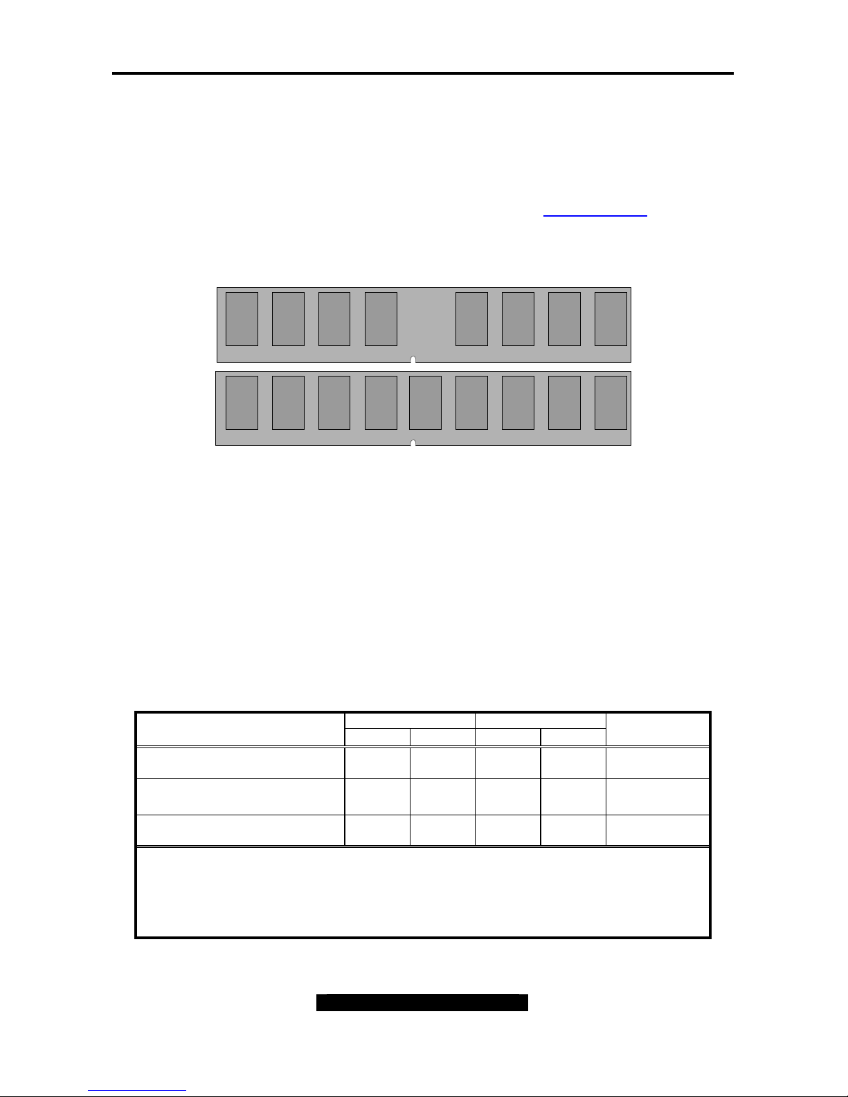
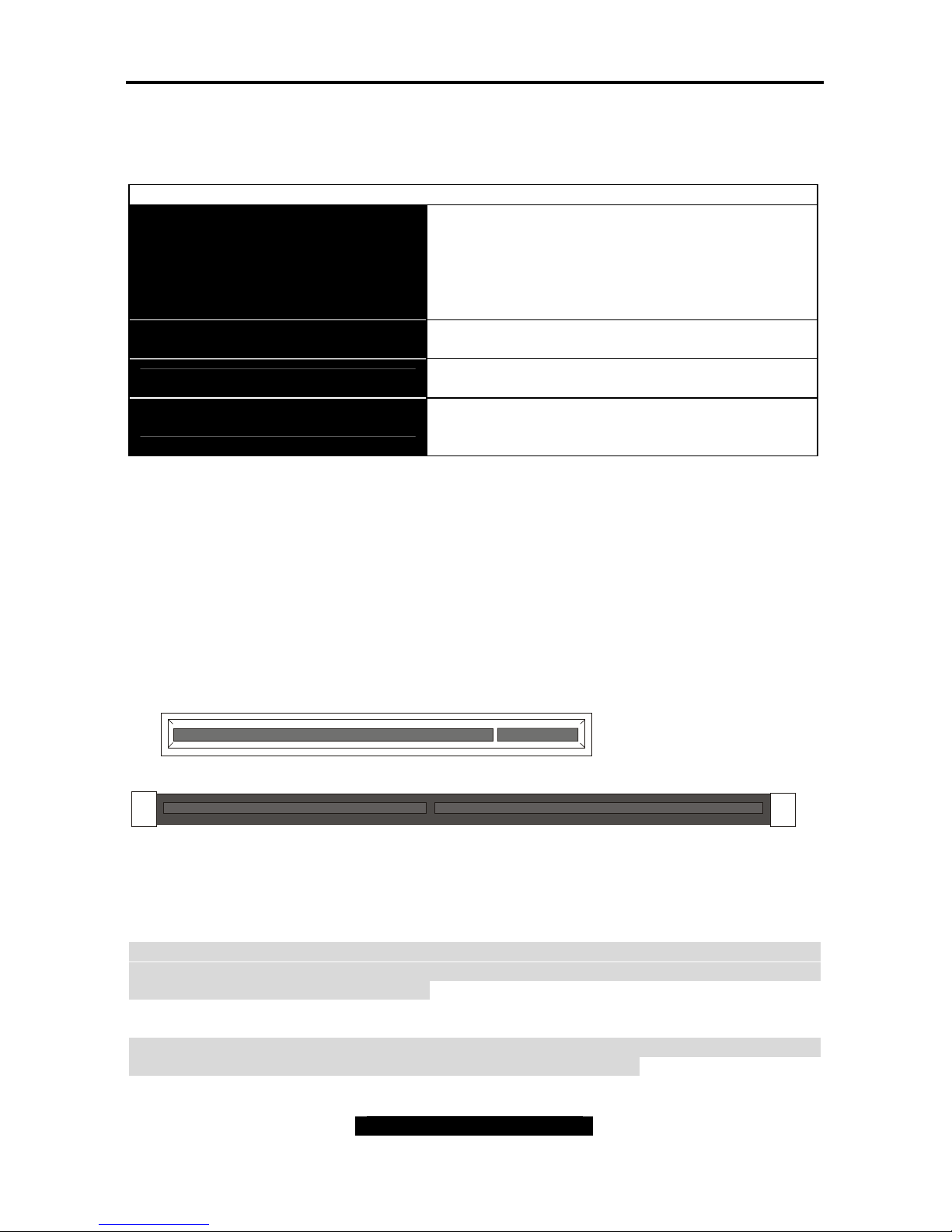
The following diagram shows the types of RAM modules you may encounter depending on
your board:
DDR Unbuffered ECC
DDR Unbuffered
Here are a few key points to note before installing memory into your Tomcat i875PF S5105:
• 128MB, 256MB, 512MB and 1GB unbuffered ECC and non-ECC
PC2100/PC2700/PC3200
DDR memory modules are supported
• All installed memory will be automatically detected - no need to set any jumpers
• The Tomcat i875PF S5105 supports up to 4GB of memory
• Registered Memory is NOT supported.
• You can install either single- or double-sided modules on this board. Each DIMM
can work respectively for single-channel mode and dual-channel mode. Please note
that the same type and density memory modules are necessary while using dualchannel DDR, otherwise it may cause system instability.
Please refer to the following table for detailed dual-channel DDR.
Channel A Channel B Dual-Channel Mode
DIMM1 DIMM2 DIMM3 DIMM4
System
Density
Two DIMM Symmetrical
Population
256MB~2GB
Two DIMM Symmetrical
Population
256MB~2GB
Four DIMM Symmetrical
Population
512MB~4GB
Note
1. : Installing128MB~1GB Memory modules
2. Symmetrical DIMMs must be identical
- Same DRAM Technology, eg 128M-bit, 256-bit, etc.
- Same DRAM bus width, eg x8 or x16
- Matched Sided DIMMs (Single Sided or Double Sided)
Tomcat i875PF S5105 Chapter 2: Board Installation
15
http://www.tyan.com
• Supported System Bus Frequency and Memory Speed Combinations
To use this type of DIMM… The processor’s system bus frequency must be…
DDR400 800MHz
DDR333 *800MHz or 533MHz
*When using an 800MHz system bus frequency processor, DDR333 memory is clocked at 320MHz.
This minimizes system latencies to optimize system throughput.
NOTE:
While using ECC type memory, it will take longer time to post. Due to the manner in which it
counts the memory and has to write zero’s to every bit of the stick before progressing through
the POST.
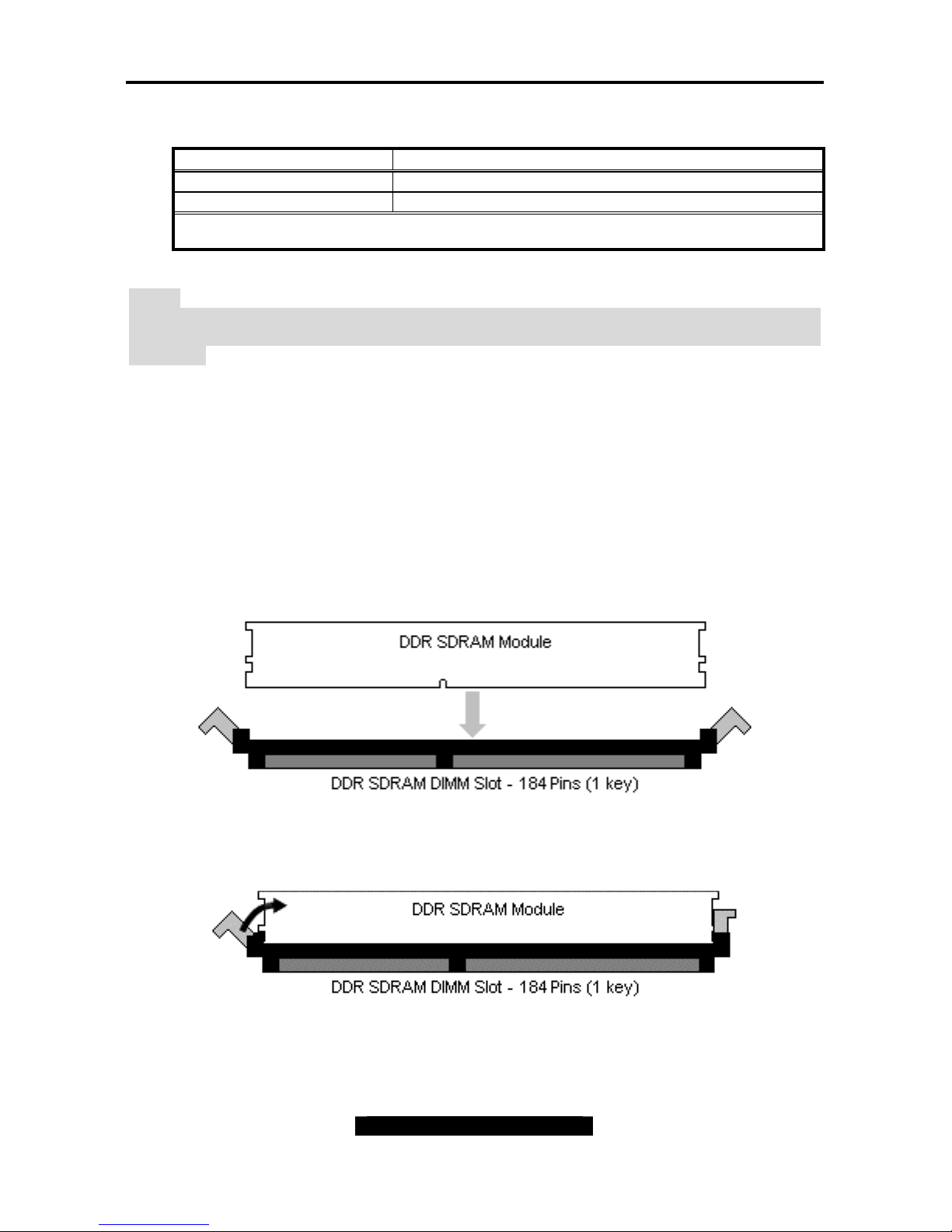
2.6 – Memory Installation Procedure
When installing memory modules, make sure the modules align properly with the memory
socket. There should be keys (small indents) on your memory modules that fit according to the
keys in the memory socket. DDR modules and sockets have only one key, which is slightly
near the center of the module/socket. The method of installing memory modules is detailed in
the following diagrams.
Once the memory modules are firmly seated in the socket, two clamps on either side will close
and secure the module into the socket. Sometimes you may need to close the clamps
manually.
To remove the memory module, simply push the clamps outwards until the memory module
pops up. Then simply remove the module.
Tomcat i875PF S5105 Chapter 2: Board Installation
16
http://www.tyan.com
TIP: When installing memory, a module may require a considerable amount of force to seat
properly, although this is very rare. To avoid bending and damaging your motherboard, place
it on its anti-static bag and onto a flat surface, and then proceed with memory installation.
Note: You MUST unplug the power connector to the motherboard before performing system
hardware changes, to avoid damaging the board or expansion device
2.7 – Installing the Processor and Heatsink
Your Tomcat i875PF S5105 supports the latest processor technologies from Intel®. Check
the following page on TYAN’s website for latest processor support:
http://www.tyan.com
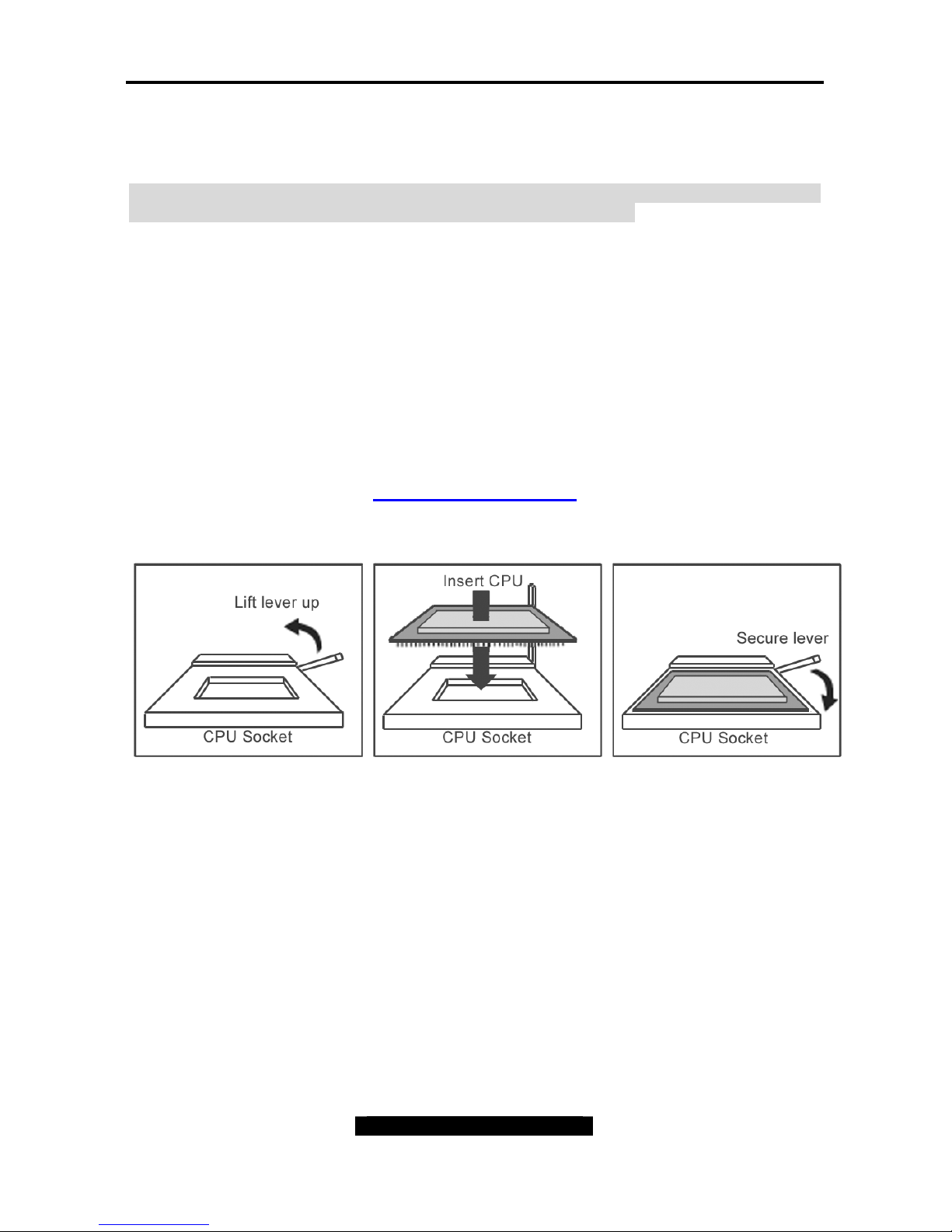
The following diagrams will detail how to install your processor:
The diagram is provided as a visual guide to help you install socket processors and may not
be an exact representation of the processors you have.
1. Lift the lever on the socket until it is approximately 90
o
or as far back as
possible to the socket.
2. Align the processor with the socket. There are keyed pins underneath the processor
to ensure that the processor’s installed correctly.
3. Seat the processor firmly into the socket by gently pressing down until the processor
sits flush with the socket.
4. Place the socket lever back down until it locks into place.
5. Your processor is installed.
Take care when installing the processor as it has very fragile connector pins below the
processor that can bend and break if inserted improperly.
Tomcat i875PF S5105 Chapter 2: Board Installation
17
http://www.tyan.com
Heatsink Installation
After you are done installing the processor, you should proceed to installing the heatsink.
Heatsink will ensure that the processor not overheat and continue to operate at maximum
performance for as long as you own them. An overheated processor is dangerous to the
health of the motherboard.
Because there are many different types of heatsinks available from many different
manufacturers, a lot of them have their own method of installation. For the safest method of
installation and information on choosing the appropriate heatsink, please refer to INTEL’s
website at www.Intel.com.
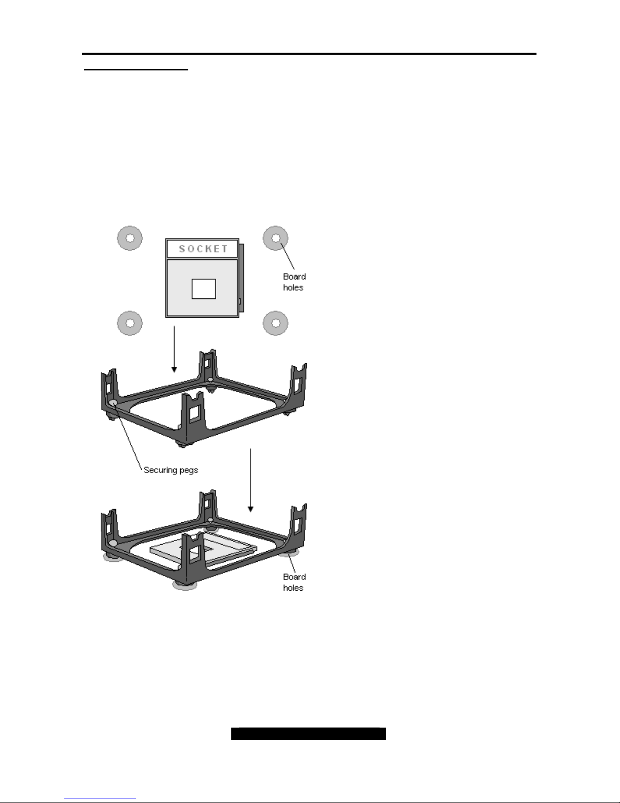
The following diagram will illustrate how to install the most common heatsinks:
Install the mounting bracket onto the
motherboard by aligning the bracket with the four
holes around the processor socket. Once the
bracket is aligned, press down on the four white
pegs on the bracket until they insert securely,
locking the bracket onto the motherboard. Then
proceed to installing the heatsink. Instructions on
how to install heatsinks should be provided with
the heatsink itself.
First, use thermal compound (also
called heatsink compound or thermal
grease) and apply a small amount on
to the processor’s core – the small
shiny square in the center of the
processor.
You may then use a small soft plastic
tool, like a credit card to gently smear
a thin layer of heatsink compound as
evenly as you can across the core. In
most cases, you don’t need to do this
but it may help.
Then, at an angle, clip one side of the
heatsink onto the socket and then lay
the heatsink flat onto the processor.
Then clip the other end of the heatsink
down either with your finger or by
using a flathead screwdriver.
Some heatsinks have a small clip on
the inside of one of the clips which
you can insert a small flathead screw
driver into to secure the heatsink.
In most cases, either side of the
heatsink can be clipped down last, but
usually, the side of the socket where it
is raised, secures last.
Because one side of the socket is
raised (and usually has “SOCKET”
imprinted into it) heatsinks have an
indent on one side to secure flush with
the raised side of the socket.
Be sure to carefully observe which
side your heatsink is seated before
securing it down to avoid damaging
the processor, the heatsink or both.
Tomcat i875PF S5105 Chapter 2: Board Installation
18
http://www.tyan.com
Finishing Installing the Heatsink
After you finish installing the heatsink onto the processor and socket, attach the end wire of
the fan (which should already be attached to the heatsink) to the motherboard. The following
diagram illustrates how to connect fans onto the motherboard.
After you’re finished installing all the fans you can connect your drives (hard drives, CD-ROM
drives, etc.) to your motherboard.
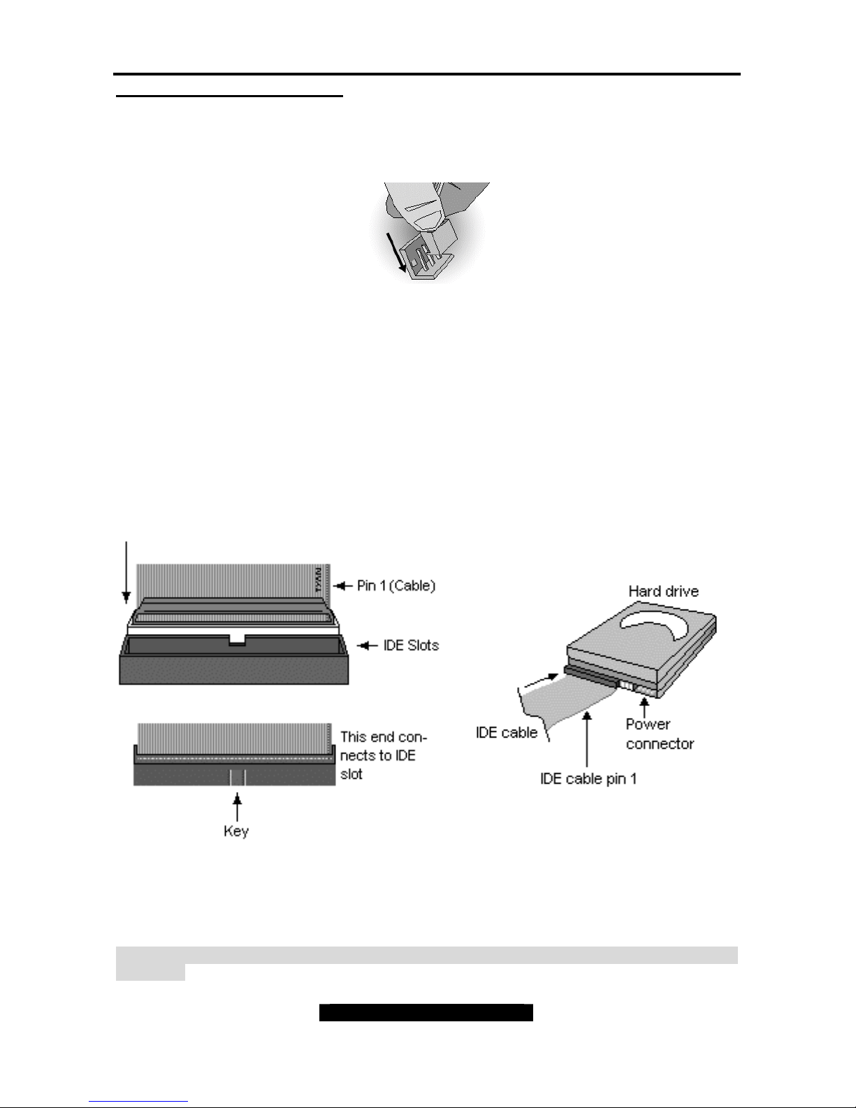
2.8 – Attaching Drive Cables
Attaching IDE drive cabling is simple. These cables are “keyed” to only allow them to be
connected in the correct manner. TYAN motherboards have two on-board IDE channels, each
supporting two drives. The black connector designates the Primary channel, while the
white connector designates the Secondary channel.
Attaching IDE cables to the IDE connectors is illustrated below:
Simply plug in the BLUE END of the IDE cable into the motherboard IDE connector, and the
other end(s) into the drive(s). Each standard IDE cable has three connectors, two of which are
closer together. The BLUE connector that is furthest away from the other two is the end that
connects to the motherboard. The other two connectors are used to connect to drives.
TIP: Pin 1 on the IDE cable (usually designated by a colored wire) faces the drive’s power
connector.
Tomcat i875PF S5105 Chapter 2: Board Installation
19
http://www.tyan.com
Serial ATA
Attaching Serial ATA cables to the Serial ATA connectors is illustrated below:
Serial ATA Cable
Serial ATA Connector
Se rial ATA H ard dr ive
Power C able
Serial ATA Cable
Simply plug in the BLACK END of the Serial ATA cable into the motherboard Serial ATA
connector, and the other end(s) into the drive(s). Each standard Serial ATA cable has two
connectors. Both BLACK ENDS of the Serial ATA cable are the same that are used to connect
to drives or motherboard.
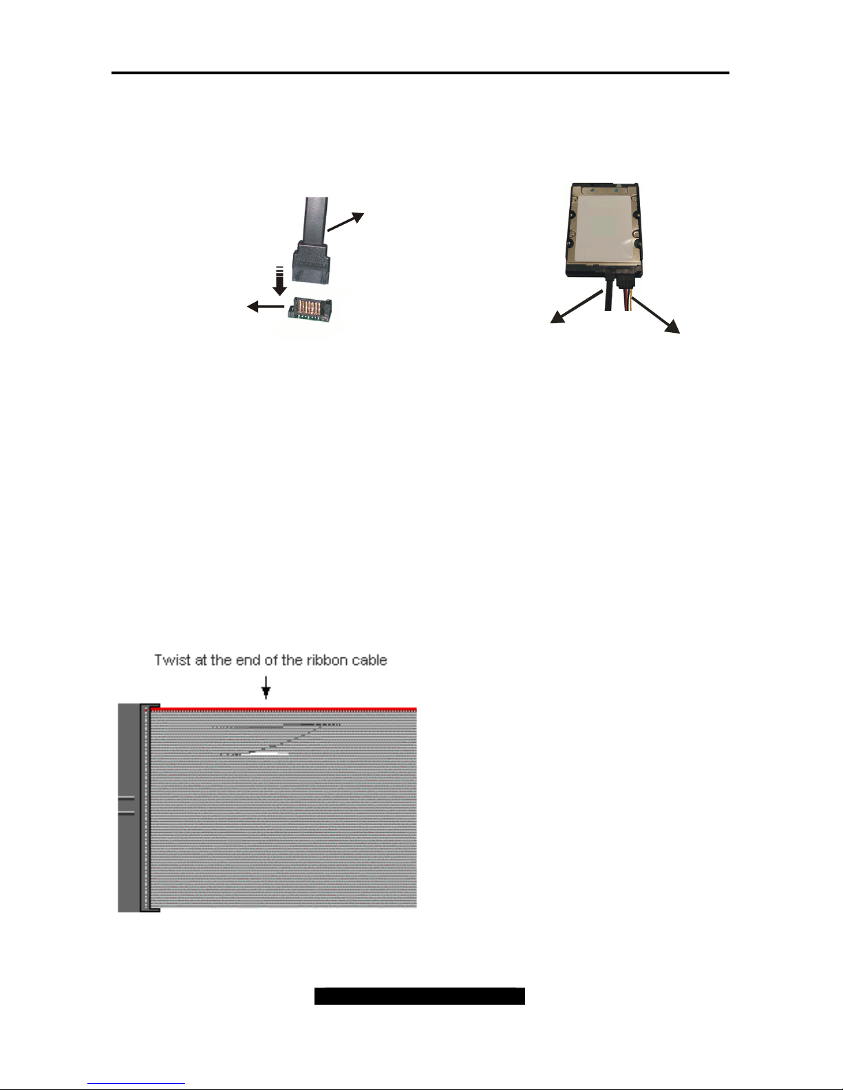
Floppy Drives
Attaching a floppy drive can be done in a similar manner to an IDE drive. See the diagram
below for an example of a floppy cable. Most of the current floppy drives on the market require
that the cable be installed with the colored stripe positioned next to the power connector. In
most cases, there will be a key pin on the cable which will force proper connection of the cable.
The first floppy drive (commonly denoted
as A:) is usually attached to the end of
the cable with the twist in it. Drive B: is
usually connected to the second or third
connector in the cable (the second or
third connector after you install Drive A:).
Refer to your floppy drive’s installation
instructions (if available), or contact your
dealer if you are unsure about how to
attach the floppy drive(s). Remember,
you can only have 2 floppy drives
connected at any given time.
Tomcat i875PF S5105 Chapter 2: Board Installation
20
http://www.tyan.com
Below are some symptoms of incorrectly installed floppy drives. While they are minor and
installing them incorrectly doesn’t cause severe problems, it may cause your system to freeze
or crash when trying to read and/or write to diskettes.
Symptoms of incorrectly installed floppy drives
Drive is not automatically detected
Usually caused by faulty cables, cables put in
backwards or a bad floppy drive or motherboard.
Try another floppy drive to verify the problem if
the cable is properly installed or try replacing the
actual cable. Also check to see if the onboard
floppy controller is enabled in the BIOS setup.
Drive Fail message at bootup
The cable, floppy drive or motherboard may be
faulty. Try another drive or cable to verify.
Drive does not power on
Check power cable and cabling. Maybe a bad
power supply or drive cable problem.
Drive activity light is constantly on
Usually signifies that the cable on the drive is on
backwards, which is a common issue. Reverse
the cable at the floppy drive end and try again.
2.9 – Installing Add-In Cards
Before installing add-in cards, it’s helpful to know if they are fully compatible with your
motherboard. For this reason, we’ve provided the diagrams below, showing the most common
slots that may appear on your motherboard. Not all of the slots shown will necessarily appear
on your motherboard, however, there will be combinations of what you see here.
32 bit - 33MHz PCI Slot - 5 Volt
s
DDR SDRAM DIMM Slot
Simply find the appropriate slot for your add-in card and insert the card firmly. Do not force any
add-in cards (or anything else) into any slots if they won’t seat in place. It’s better to try
another slot or return the faulty card rather than damaging both the motherboard and the addin card.
TIP: It’s a good practice to install add-in cards in a staggered manner, rather than directly
adjacent to each other. This allows air to more easily circulate within the chassis, providing
improved cooling for all installed devices.
Note: YOU MUST unplug the power connector to the motherboard before performing system
hardware changes, to avoid damaging the board or expansion device.
Tomcat i875PF S5105 Chapter 2: Board Installation
21
http://www.tyan.com
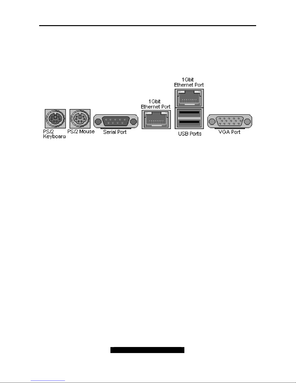
2.10 – Connecting External Devices
Connecting external devices to the motherboard is an easy task. The standard devices you
should expect to plug into the motherboard are keyboards, mice, and printer cables. The
following diagram will detail the ATX port stack for the following board:
Tomcat i875PF S5105
More on the uncommon side these days are the Serial Ports. They were primarily used to
connect external modems, but most modems today are using USB or are installed internally.
TIP: While the ports have been created to accept connectors in only one direction, make sure
to be careful when inserting connectors. At times, attaching connectors in the incorrect
orientation can damage, bend and or break the pins.
2.11 – Installing the Power Supply
There are two power connectors on this motherboard. By default, this motherboard requires
that you have an ATX12V power supply that has the standard ATX-style 20-pin connector, as
well as an additional 4-pin square connector. The CPU power is provided by the onboard
switching voltage regulator, which is sourced by +12V power. This +12V CPU power source is
from the onboard 4-pin square connector. The +12V power on the 20-pin ATX power
connector is for system board and separated from CPU +12V regulator power source.
Therefore, the CPU will not be powered if you do not connect the 4-pin square ATX 12V power
connector.
 Loading...