

TYAN S4985G3NR User Manual

1
Thunder n4250QE
///
S4985G3NR
Version 1.00
Copyright
Copyright © TYAN Computer Corporation, 2006. All rights reserved. No part of
this manual may be reproduced or translated without prior written consent from
TYAN Computer Corp.
Trademark
All registered and unregistered trademarks and company names contained in
this manual are property of their respective owners including, but not limited to
the following.
TYAN, Thunder n4250QE are trademarks of TYAN Computer Corporation.
AMD, Opteron, and combinations thereof are trademarks of AMD Corporation.
Phoenix, Phoenix-AwardBIOS are trademarks of Phoenix Technologies.
Notice
Information contained in this document is furnished by TYAN Computer
Corporation and has been reviewed for accuracy and reliability prior to printing.
TYAN assumes no liability whatsoever, and disclaims any express or implied
warranty, relating to sale and/or use of TYAN products including liability or
warranties relating to fitness for a particular purpose or merchantability. TYAN
retains the right to make changes to product descriptions and/or specifications
at any time, without notice. In no event will TYAN be held liable for any direct or
indirect, incidental or consequential damage, loss of use, loss of data or other
malady resulting from errors or inaccuracies of information contained in this
document.

2
Table of Contents
Check the box contents! 3
Chapter 1: Introduction
1.1 Congratulations…………………………………………………………… 5
1.2 Hardware Specifications………………………………………………… 5
Chapter 2: Board Installation
2.1 Board Image……………………………………………………………… 8
2.2 Block Diagram……………………………………………………………. 9
2.3 Board Parts, Jumpers and Connectors………………………………... 10
2.4 Tips on Installing Motherboard in Chassis…………………………….. 20
2.5 Installing the Processor(s)………………………………....................... 21
2.6 Installing the Memory……………………………………………………. 24
2.7 Attaching Drive Cables………………………………………………….. 26
2.8 Installing Add-in Cards………………………………............................ 28
2.9 Connecting External Devices…………………………………………… 29
2.10 Installing the Power Supply……………………………………………... 30
2.11 Finishing up………………………………………………………………. 30
Chapter 3: BIOS Setup
3.1 About the BIOS…………………………………………………………… 31
3.2 BIOS Main Menu…………………………………………………………. 33
3.3 Advanced Menu………………………………………………………….. 41
3.4 Security Menu…………………………………………………………….. 54
3.5 Power Menu………………………………………………………………. 55
3.6 Boot Menu………………………………………………………………… 56
3.7 Exit Menu…………………………………………………………………. 57
Chapter 4: Diagnostics
4.1 Beep Codes………………………………………………………………. 59
4.2 Flash Utility……………………………………………………………….. 59
4.3 BIOS Post Code………………………………………………………….. 60
Appendix I: SMDC Information
Appendix II: How to Make a Driver Diskette
Glossary
3
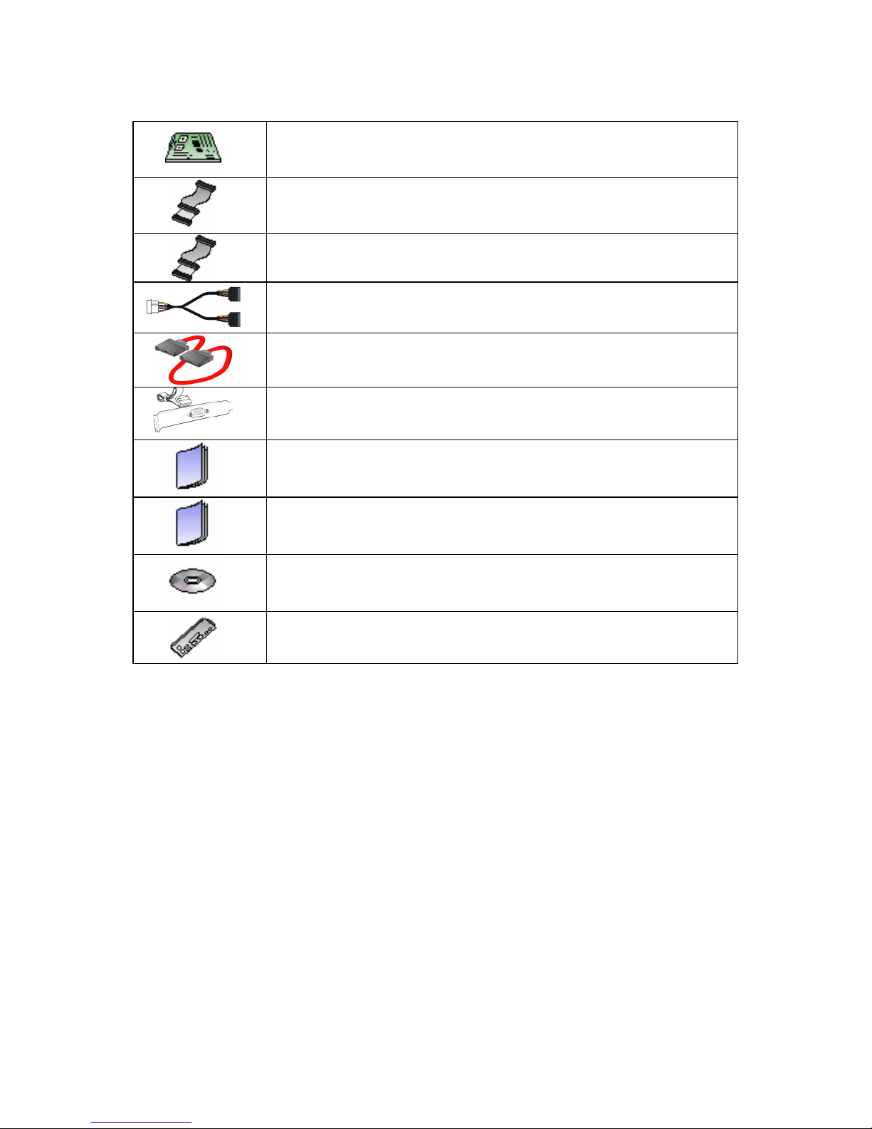
Check the box contents!
1x S4985 motherboard
1x 34-Pin floppy drive cable
2 x Ultra-DMA-133/100/66/33 IDE cable
2 x Serial ATA power cable
4 x Serial ATA Cable
1 x COM Port Cable
1 x S4985 user’s manual
1 x S4985 Quick Reference guide
1 x TYAN driver CD
1 x I/O shield
If any of these items are missing, please contact your vendor/dealer for
replacement before continuing with the installation process.

4

5
Chapter 1: Introduction
1.1 - Congratulations
You have purchased the high performance server with four processors (can
expand to eight). The Thunder n4250QE (S4985G3NR) is a flexible AMD®
platform for multiple applications, based on NVIDIA
®
nForce Professional 2200
(CK804pro) and NVIDIA nForce Professional 2050 (IO4) chipsets.
Designed to support four AMD
®
Opteron processors and max 64GB DDR2667/533/400 memory, and featured with integrated RJ-45 LAN connectors, PCIExpress x16 slots plus eight serial ATA ports, the S4985 offers exceptional
performance and versatile solution for your server platform.
Remember to visit TYAN’s Website at http://www.TYAN.com
. There you can
find information on all of TYAN’s products with FAQs, online manu als and BIOS
upgrades.
1.2 - Hardware Specifications
Processors
•Supports four AMD Opteron
TM
Socket F (1207) 8000 series
processors
•Four onboard 5-phase digital
VRMs
Chipset
•NVIDIA nForce Professional 2200
(CK804pro)
•NVIDIA nForce Professional 2050
(IO4)
•Winbond W83627HF Super I/O
•Three Analog Devices ADT7476
Hardware Monitoring IC
Memory
•Dual channel memory bus
•Sixteen DDR2 DIMM sockets
(Four per CPU)
•Supports up to 64GB Registered
DDR2 memory
•Supports ECC type memory
modules
•Supports DDR2-667/533/400
Integrated LAN Controller
•Two (2) Marvell 88E1111 GbE
PHY
- Each one has RJ-45 LAN
connector with LEDs
- Each one has front panel LED
header
•One Intel 82541PI GbE LAN
controller
- RJ-45 LAN connector with LED
Integrated Video Controller
•XGI XG20
•PCI interface
•16MB DDR memory
Intelligent Platform
Management Interface Header
•Tyan Server Management
Daughter card (optional) supports
features listed below via IPMI
header
- Renesas Baseboard
Management Controller (BMC)
- Tailored for IPMI 2.0 spec.

6
•Supports four rank memory
Expansion Slots
•Two (2) x16 PCI Express slots
with x16 signal
•Two (2) x16 PCI Express slots
with x4 signal
•One 32bit/33MHz PCI v2.3 slot
•Total of five usable slots
Integrated I/O
•One (1) floppy connector supports
up to two drives
•One (1) parallel port header and
two (2) serial ports (one
connector, one header)
•Six (6) USB 2.0 EHCI ports (two
rear connectors & four headers)
•PS/2 mouse and keyboard
connectors
System Management
•Modular BMC 2x25 pin header for
SMDC support
•Six (6) 4-pin fan headers support
tachometer monitoring and smart
FAN control (PWM), four (4) 3pin fan headers support
tachometer monitoring
•Temperature and voltage
monitoring
•Port 80h LED display
Integrated ATA-133
•Two (2) ATA-133 channels for up
to four (4) ATA-133 devices
Integrated SATA Controllers
•Four (4) integrated dual port
SATA controllers (two from
CK804pro and two from IO4)
•Supports up to eight (8) SATA
drives
•Supports up to 3.0Gb/s
•Supports four (4) independent
SATA ports
•Supports RAID 0, 1, 0+1, 5
- Supports KCS and BT styles
- Flexible Windows or Linux
Management Solution
- Supports RMCP and SNMP
protocols
- Supports ASF standard and EMP
-1
2
C serial multi-master controllers
and UARTs
- Built-in IPMB connector
- Remote power on/off and reset
support (IPMI-over-LAN)
BIOS
•PhoenixBIOS on 8Mbit LPC Flash
ROM
•ACPI 2.0
•Serial Console Redirect
•USB device boot
•48-bit LBA support
•Power management: S0, S1, S4
and S5
Form Factor
•SSI MEB Footprint (13” x 16”)
•EPS12V/SSI v3.5 (24+8+8) power
connectors
•One (1) serial connector and one
(1) VGA port
•Stacked USB 2.0 connectors
•Stacked PS/2 keyboard and
mouse connectors
•Three (3) RJ-45 LAN connectors
with LEDs
Power Supply
•EPS 12V Power Supply

7
Chapter 2: Board Installation
You are now ready to install your motherboard. The mounting hole pattern of
the Thunder n4250QE S4985G3NR matches the SSI MEB specification. Before
continuing with installation, confirm that your chassis supports an SSI MEB
motherboard.
How to install our products right… the first time
The first thing you should do is reading this user’s manual. It contains important
information that will make configuration and setup much easier. Here are some
precautions you should take when installing your motherboard:
(1) Ground yourself properly before removing your motherboard from the
antistatic bag. Unplug the power from your computer power supply and
then touch a safely grounded object to release static charge (i.e. power
supply case). For the safest conditions, TYAN recommends wearing a
static safety wrist strap.
(2) Hold the motherboard by its edges and do not touch the bottom of the
board, or flex the board in any way.
(3) Avoid touching the motherboard components, IC chips, connectors,
memory modules, and leads.
(4) Place the motherboard on a grounded antistatic surface or on the
antistatic bag that the board was shipped in.
(5) Inspect the board for damage.
The following pages include details on how to install your motherboard into your
chassis, as well as installing the processor, memory, disk drives and cables.
NOTE
DO NOT APPLY POWER TO THE BOARD IF IT HAS BEEN
DAMAGED
8
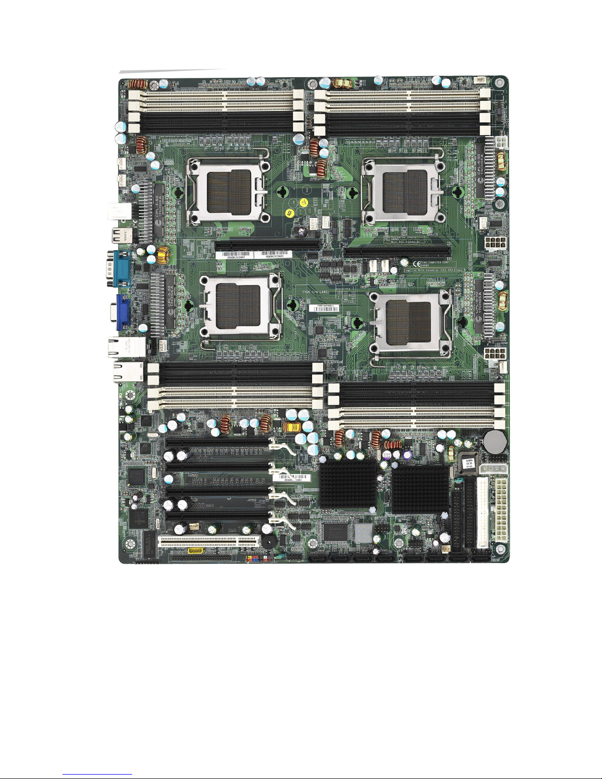
2.1- Board Image
This picture is representative of the latest board revision available at
the time of publishing. The board you receive may or may not look
exactly like the above picture.
9
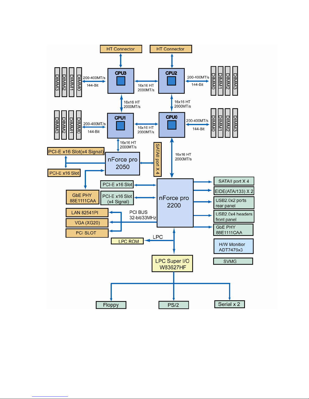
2.2 - Block Diagram
Thunder n4250QE S4985G3NR Block Diagram
10
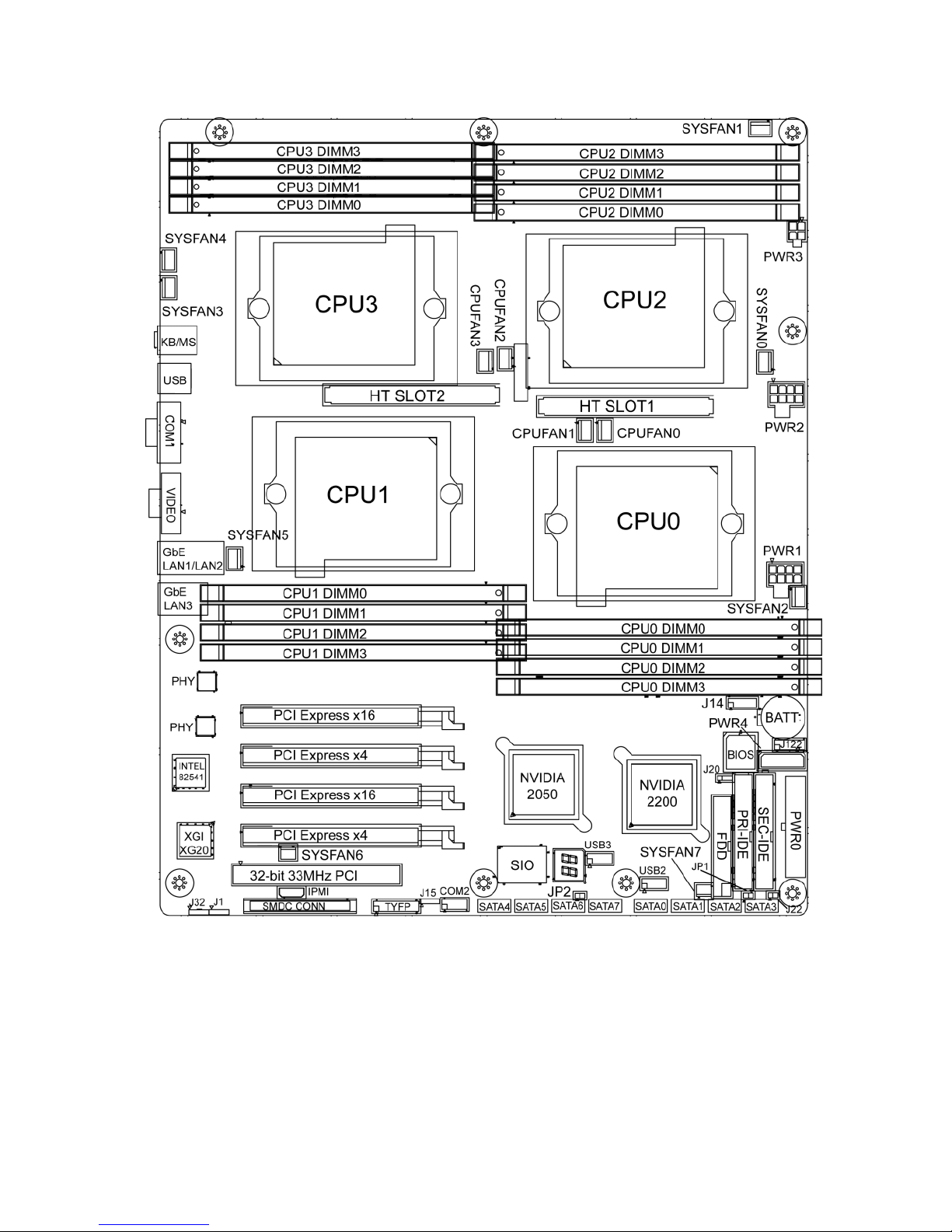
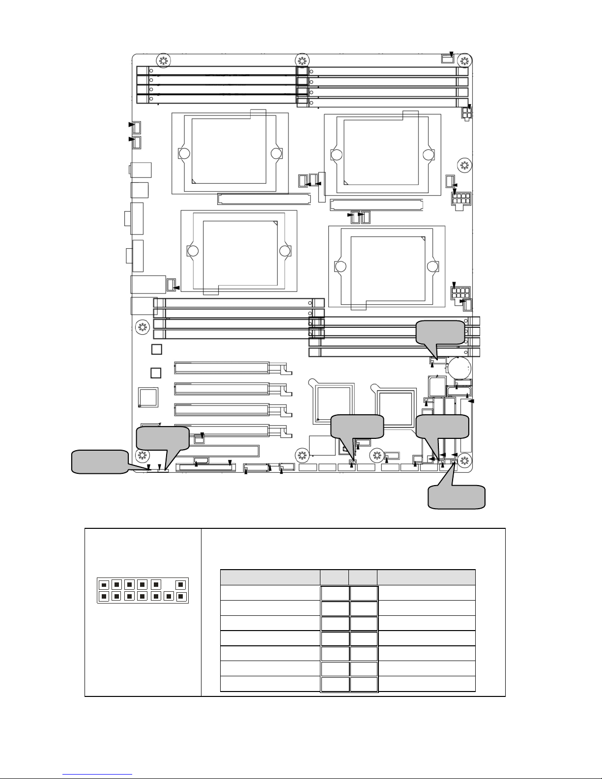
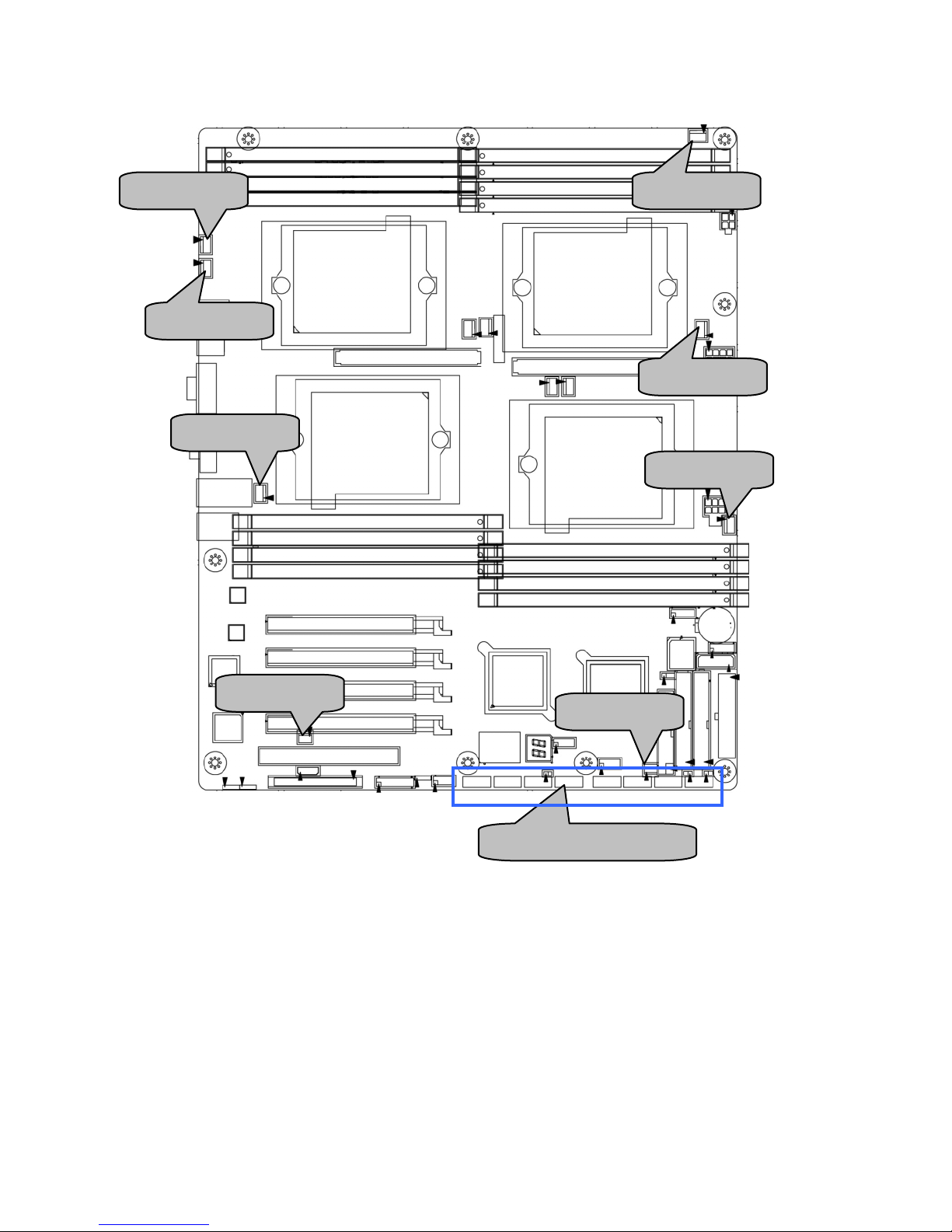
2.3 - Board Parts, Jumpers and Connectors
This diagram is representative of the latest board revision available at the time of
publishing. The board you receive may not look exactly like the above diagram.
11
Jumper Legend
OPEN - Jumper OFF, without jumper cover
CLOSED – Jumper ON, with jumper cover
Jumper/Connector Function
J1 SMBUS Connector
J14 Fan Connector (for barebone use only)
J20
Clear CMOS Jumper
- Pin 2-3 closed: Normal (Default)
- Pin 1-2 closed: Clear
J22 NMI Header
J30/J95
USB Front Panel Headers
J30: USB2
J95: USB3
J101 COM2 Header
J115 Front Panel Header
JP1 RI Header
JP2 Intruder Header
CPUFAN0/1/2/3 CPU Fan Connectors
SYSFAN0/1/2/3/4/5/6/7 Chassis Fan Connectors
SATA0/1/2/3/4/5/6/7 Serial ATA RAID Connectors
12
J14: FAN Connector (for barebone use only)
2
1
3
1
14
Use these pin definitions to connect to the barebone
fans.
Signal Pin Pin Signal
CPUFAN0_TACH
1 2
CPUFAN2_TACH
CPUFAN1_TACH
3 4
CPUFAN3_TACH
SYSFAN0_TACH
5 6
CPU_FAN_TACH2
SYSFAN4_TACH
7 8
SYSFAN5_TACH
NC
9 10
NC
GND
11 12
Key
GND
13 14
CPUFAN0_PWM
JP1
J1
J14
J22
JP2
J32
13
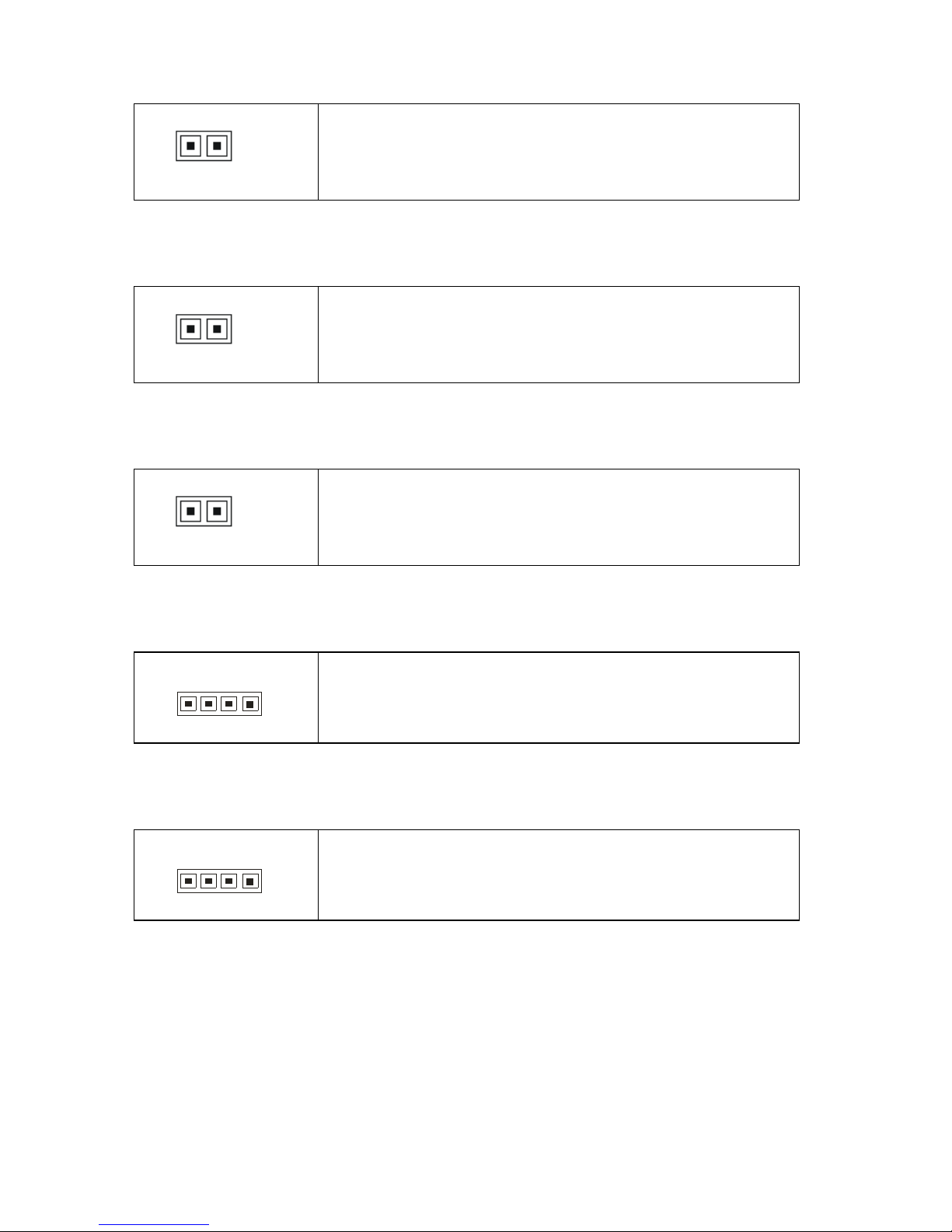
JP1: RI Header
1
Use this header to connect to the external device
of wake on ring.
JP2: Intruder Header
1
Use this header to connect to the device for
intruder function .
J22: NMI Header
1
Use this header to issue a non-maskable
interrupt.
J1: SMBUS Connector
1
Use this header to connect to the external
SMBUS devices.
J32: External SCSI LED Connector
1
Use this header to connect to the external SCSI
LED.
14
J115: Front Panel Header
The Front Panel Header is used to connect some control or signal wires from
motherboard to chassis, such as HDD LED, power LED, power button, and
reset button.
HDDLED+
1 2
PWR LED+
HDDLED-
3 4
PWR LED-
Reset SW
5 6
PWR SW
Reset SW
7 8
PWR SW
VCC
9 10
NC
IRRX
11 12
VCC
GND
13 14
key
IRTX
15 16
GND
NC
17 18
Speaker
J115
J20
J101
J30
J95

15
J20: Clear CMOS Jumper
3
1
Normal
(Default)
1 3
Clear
Use this jumper when you forgot your system/setup
password or need to clear system BIOS setting.
How to clear the CMOS data
- Power off system and disconnect power
supply from AC source
- Use jumper cap to close Pin_1 and 2 for
several seconds to Clear CMOS
- Replace jumper cap to close Pin_2 and 3
Reconnect power supply to AC source
Power on system
J101: COM2 Header
1
9
2 10
Use these pin definitions to connect a port to COM2.
*TYAN does not provide cable for this header. It is
designed for OEM use only.
Signal Pin Pin Signal
DCD
1 2
DSR
RXD
3 4
RTS
TXD
5 6
CTS
DTR
7 8
RI
GND
9 10
Key
J30/J95: USB Front Panel Headers
1
9
2 1
0
J30: USB2
J95: USB3
Signal Pin Pin Signal
VCC
1 2
VCC
Data-
3 4
Data-
Data+
5 6
Data+
GND
7 8
GND
Key
9 10
NA
Use these headers to connect to the USB devices
via the enclosed USB cable.
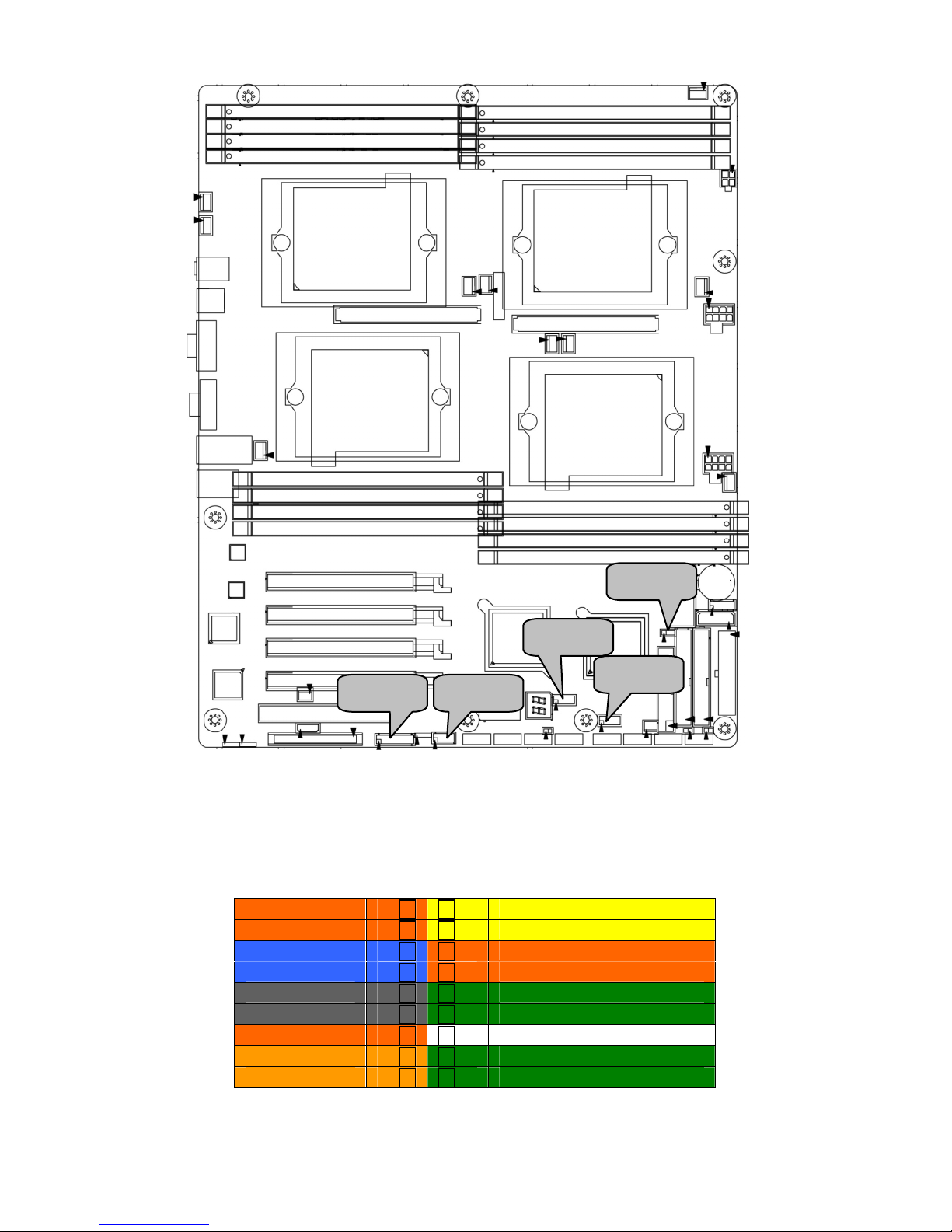
16
SYSFAN4
SATA 0/1/2/3/4/5/6/7
SYSFAN3
SYSFAN6
SYSFAN2
SYSFAN1
SYSFAN0
SYSFAN5
SYSFAN7
17
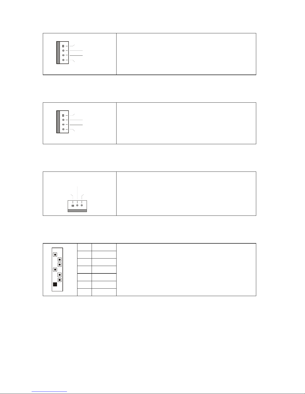
CPUFAN0/CPUFAN1/CPUFAN2/CPUFAN3: CPU Fan Connectors
12V
PWM
GND
Ta c ho met e r
Use this header to connect the processor cooling
fan to your motherboard to keep the system at
optimum performance levels.
SYSFAN0/SYSFAN1/SYSFAN2/SYSFAN3/SYSFAN4/SYSFAN5: Chassis
Fan Connectors
12V
PWM
GND
Ta c ho met e r
Use this header to connect the chassis cooling
fan to your motherboard to keep the system at
optimum performance levels.
SYSFAN6/SYSFAN7: Chassis Fan Connectors
+12V
SpeedGND
Use this header to connect the chassis cooling
fan to your motherboard to keep the system at
optimum performance levels.
SATA0/1/2/3/4/5/6/7: Serial ATA RAID Connectors
7 GND
6 RXP
5 RXN
4 GND
3 TXN
2 TXP
7
1
1 GND
Connects to the Serial ATA ready drives via the
Serial ATA cable
You may use these eight Serial ATA ports to
have the support of RAID 0, 1, 0+1 or 5
through the on board NVIDIA nForce
Professional chipset (CK804pro & IO4).
18
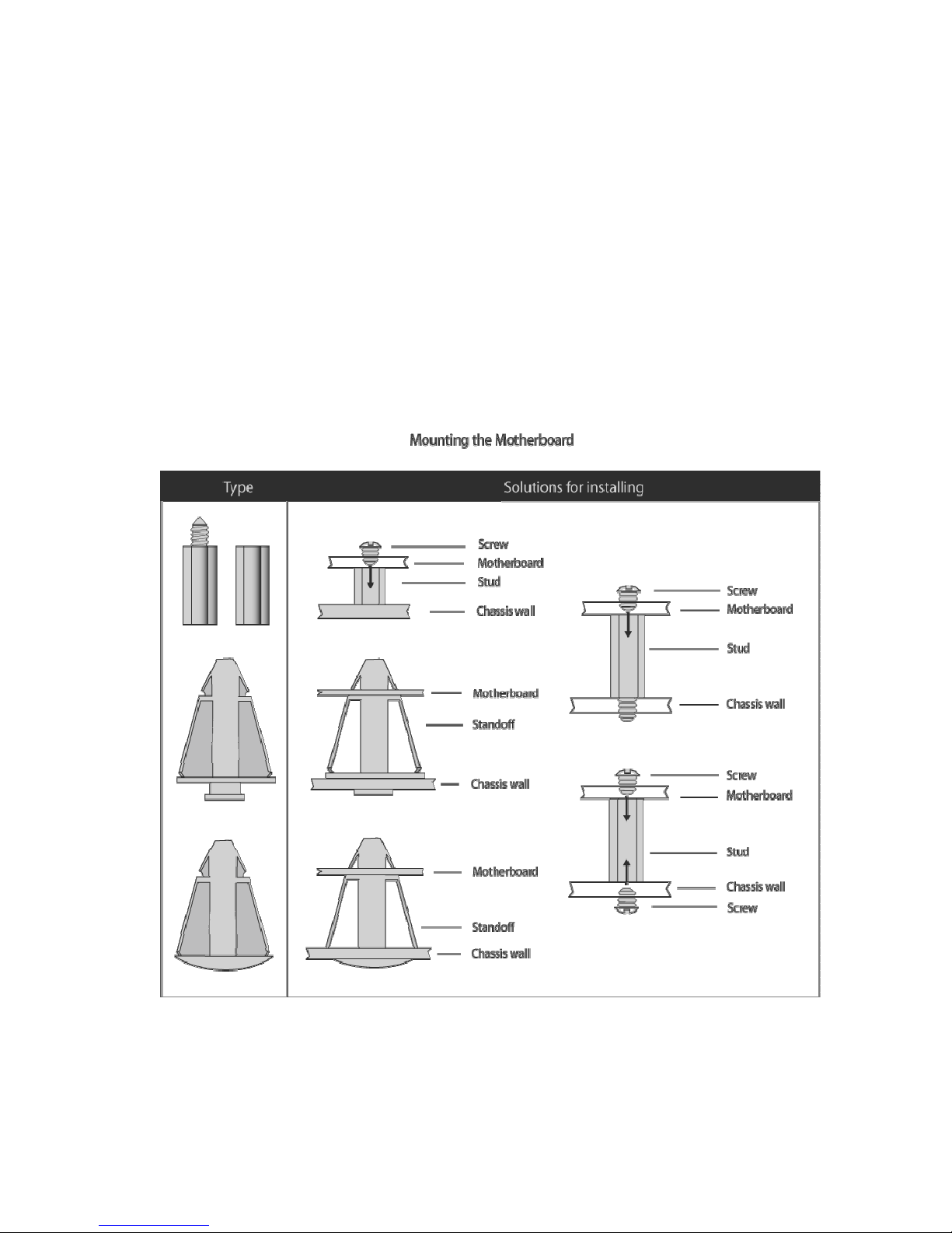
2.4 - Tips on Installing Motherboard in Chassis
Before installing your motherboard, make sure your chass is has the
necessary motherboard support studs installed. These studs are usually
metal and are gold in color. Usually, the chassis manufacturer will pre-install
the support studs. If you are unsure of stud placement, simply lay the
motherboard inside the chassis and align the screw holes of the
motherboard to the studs inside the case. If there are any studs missing,
you will know right away since the motherboard will not be able to be
securely installed.
Some chassis’ include plastic studs instead of metal. Although the plastic
studs are usable, TYAN recommends using metal studs with screws that will
fasten the motherboard more securely in place.
Below is a chart detailing what the most common motherboard studs look
like and how they should be installed.

19
2.5 - Installing the Processor(s) & Heatsink(s)
Your Thunder n4250QE S4985G3NR supports the latest processor
technologies from AMD. Check the TYAN website for latest processor support:
http://www.tyan.com
20
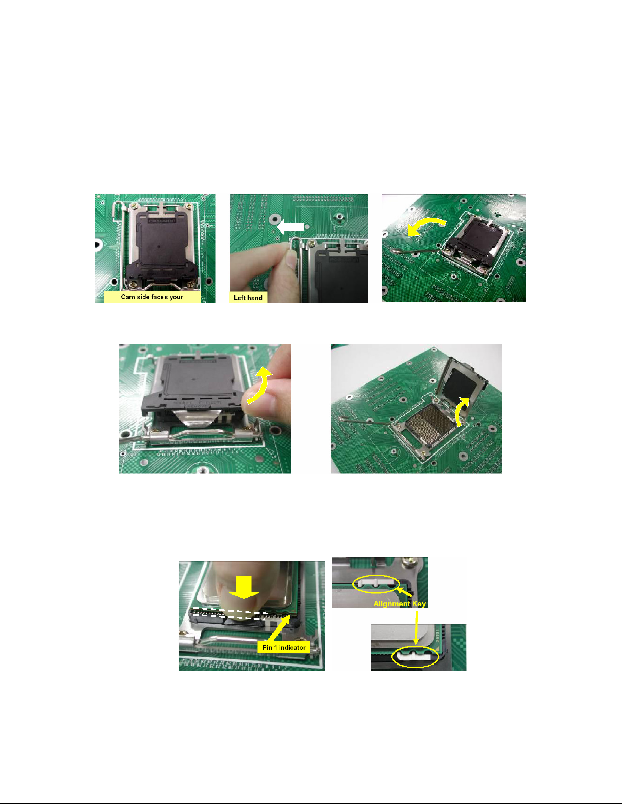
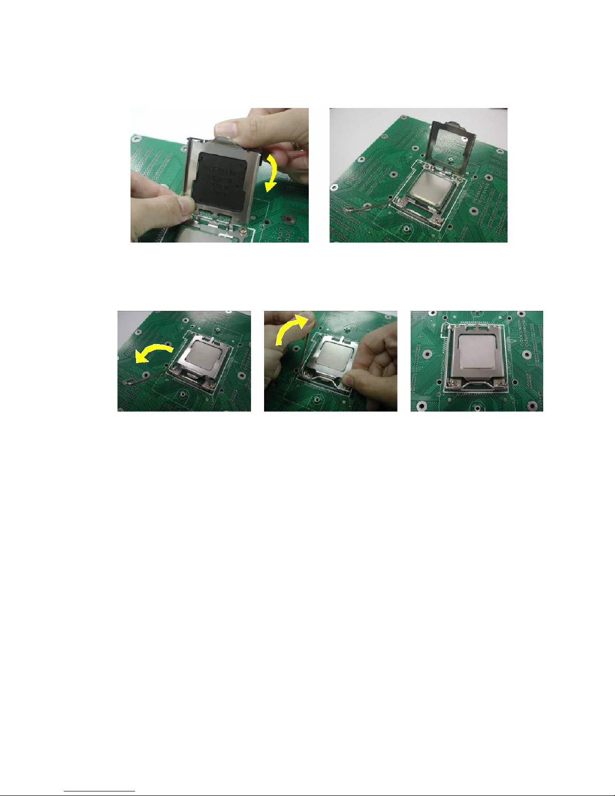
Processor Installation
The processor should be installed carefully. Make sure you are wearing an
antistatic strap and handle the processor as little as possible.
Follow these instructions to install your processor:
1. Place the PCB such that the socket cam side faces you. Make sure
the lever hook is on your top-left side.
2. Use your left thumb and forefinger to hold the lever hook, then pull it
to the left side to clear the retention tab.
3. Rotate the lever to a fully open position.
4. Lift the load plate to a fully open position.
5. Locate the Pin 1 indicator of the package. Align the package with the
socket and carefully insert the package into the socket with vertical
motion only. Vertically check if the CPU is seated well in the socket
housing. If not, take out the CPU, with vertical motion only, and
repeat the above steps.
NOTE: The alignment keys must be located in the notches of the package.
21
6. Remove the PnP cap. Use your left hand to hold the load plate.
Then use your right thumb to remove the PnP cap from the load plat e.
With the package in the socket, the PnP cap removal process will not
damage the contacts.
7. Close the socket. Rotate the load plate onto the package lid.
Engage the load lever while pressing down lightly onto the l oad plate.
Secure the lever near the hook end under the retention tab.
8. Repeat this procedure for the second processor if necessar y.
22
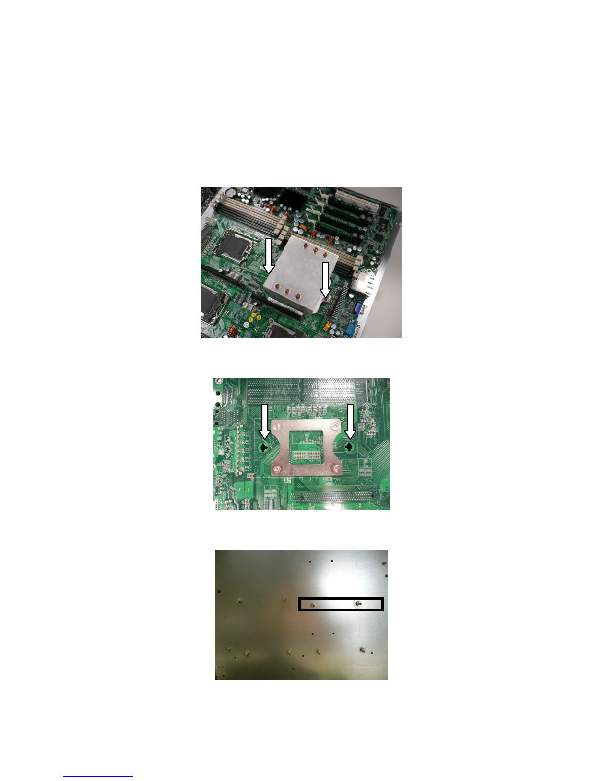
Heatsink Installation
While installing the heatsink, be careful in mounting the heatsink into the
chassis to enhance the support of shock and vibration acting on the
heatsink. Do not mount the heatsink into the back plate only to prevent
excessive pressure on the PCB that will cause serious damage to processor
socket and mainboard.
Follow these instructions to install your heatsink:
1. Put the heatsink onto the CPU socket after installing CPU. Secure
the heatsink with two screws as illustrated onto the chassis.
NOTE: The back plate is already mounted on the backside of mainboard. You
don’t need to pay additional attention on mounting the back plate.
NOTE: There are eight mounting holes for the heatsinks on the chassis. Locate
the two mounting holes for each heatsink before mounting the heatsink into the
chassis (example as indicated).
Attention! Install the heatsink
into the two holes as indicated
from the front side of
mainboard
.
23
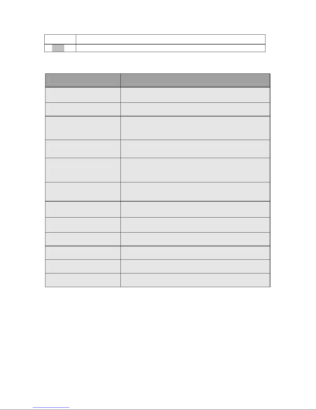
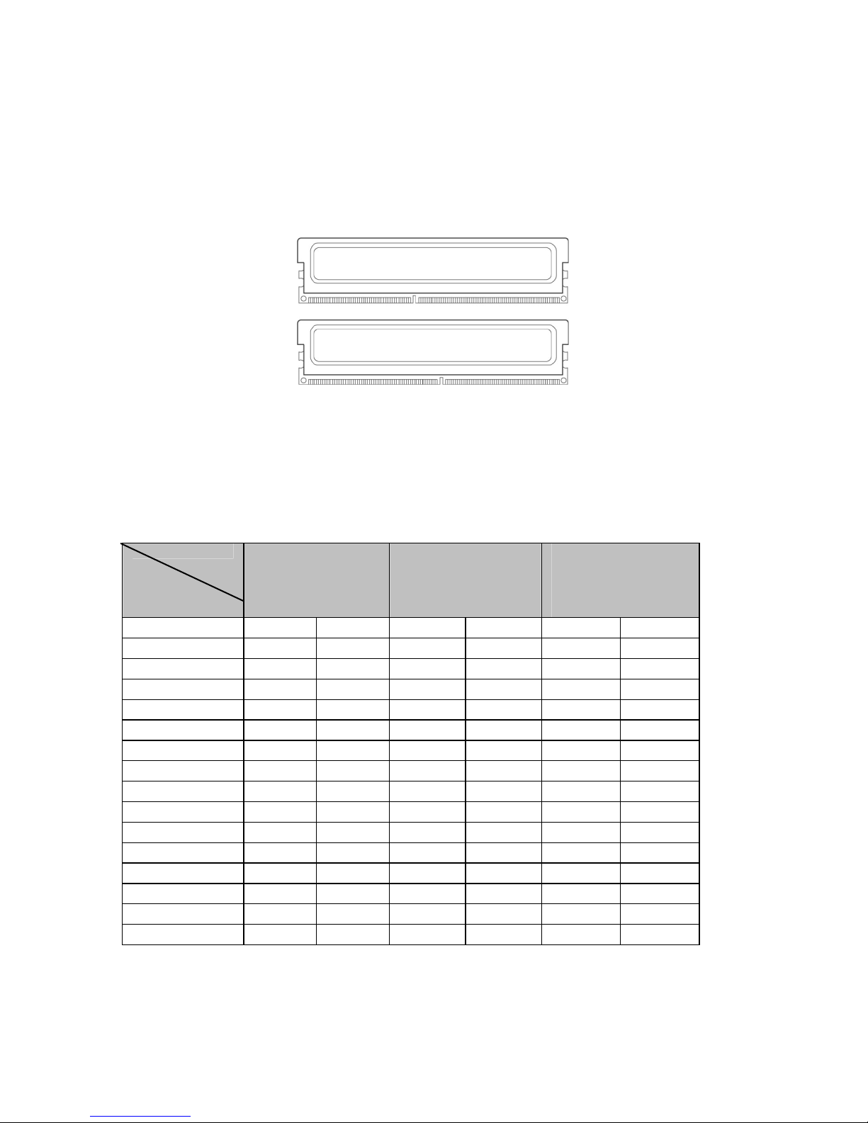
2.6 - Installing the Memory
Before installing memory, ensure that the memory you have is compatible with
the motherboard and processor. Only DDR2-667/533/400 DIMM modules are
required. Check the TYAN Web site at: www.tyan.com for details of the type
of memory recommended for your motherboard.
The following diagram shows common types of DDR2 memory modules.
• All insta lled memory will automatically be detected and no jumpers or
settings need changing.
• The Thunder n4250QE S4985G3NR supports up to 64GB of memory.
The following chart outlines the suggested rules for populating memory.
Memory Population Rules
CPU
Single
(CPU 0 only)
Dual
(CPU 0 & CPU1)
Four
(CPU 0, CPU1,
CPU2 & CPU3)
CPU0DIMM0 x x x
CPU0DIMM1 x x x
CPU0DIMM2 x x x x x x
CPU0DIMM3 x x x x x x
CPU1DIMM0 x x
CPU1DIMM1 x x
CPU1DIMM2 x x x x
CPU1DIMM3 x x x x
CPU2DIMM0 x
CPU2DIMM1 x
CPU2DIMM2 x x
CPU2DIMM3 x x
CPU3DIMM0 x
CPU3DIMM1 x
CPU3DIMM2 x x
CPU3DIMM3 x x
NOTE: Please always install memory beginning with CPU0DIMM0. You can
choose to install single, dual or four memory modules.
DIMM
24
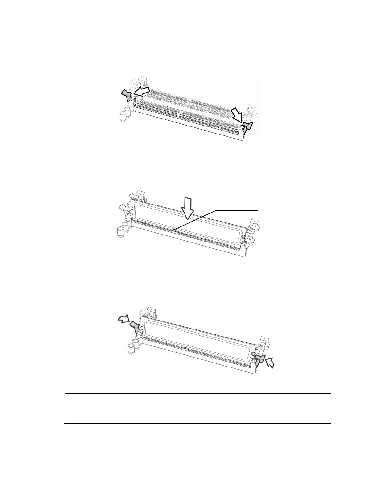
Memory Installation Procedure
Follow these instructions to install memory modules into the Thunder n4250QE
S4985G3NR.
1. Press the locking levers in the direction shown in the following illustration.
2. Align the memory module with the socket. The memory module is keyed
to fit only one way in the socket.
3. Seat the module firmly into the socket by gently pressing down until it sits
flush with the socket. The locking levers pop up into place.
NOTE: The S4985 only supports DDR2 DIMM. Registered Memory Module is
NOT supported.
Key slot
25
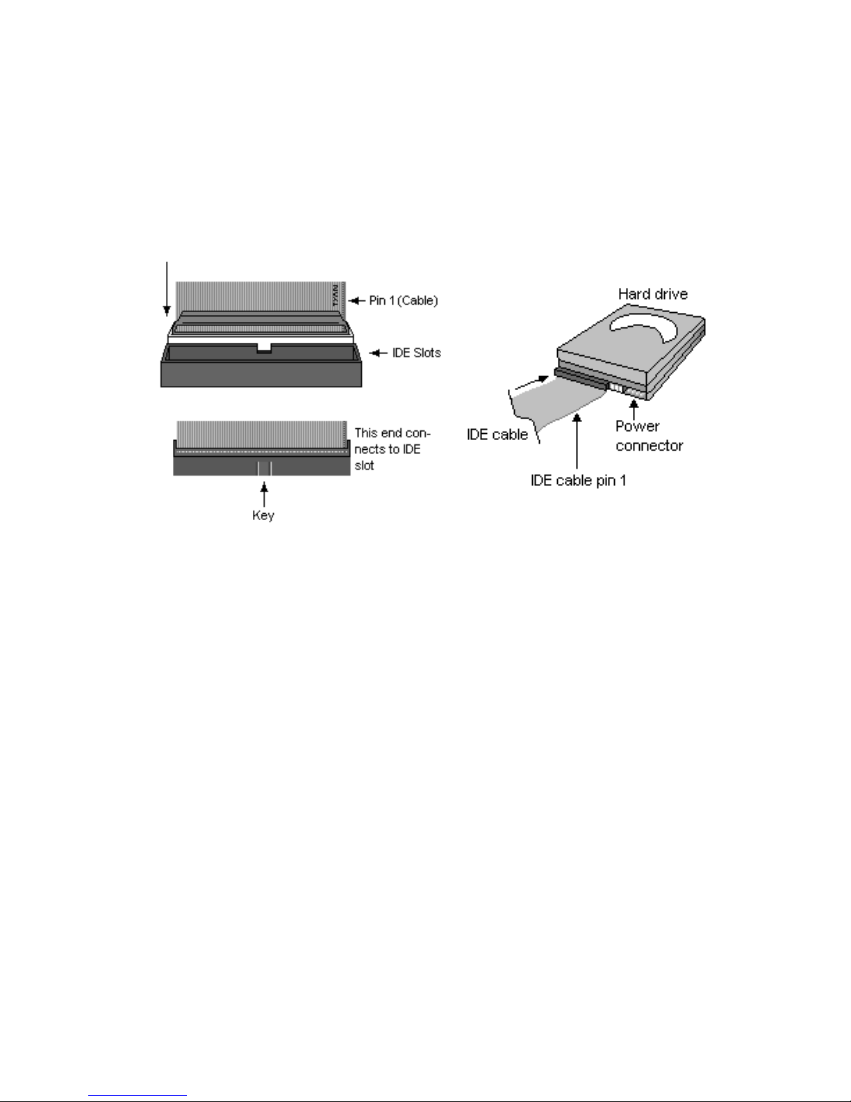
2.7 - Attaching Drive Cables
Attaching IDE Drive Cable
Attaching the IDE drive cable is simple. These cables are “keyed” to only
allow them to be connected in the correct manner. TYAN motherboards
have two on-board IDE channels, each supporting two drives. The black
connector designates the Primary channel, while the white connector
designates the Secondary channel.
Attaching IDE cables to the IDE connectors is illustrated below:
Simply plug in the BLUE END of the IDE cable into the motherboard IDE
connector, and the other end(s) into the drive(s). Each standard IDE cable
has three connectors, two of which are closer together. The BLUE
connector that is furthest away from the other two is the end that connects
to the motherboard. The other two connectors are used to connect to drives.
NOTE: Always remember to properly set the drive jumpers. If only using
one device on a channel, it must be set as Master for the BIOS to detect it.
TIP: Pin 1 on the IDE cable (usually designated by a colored wire)
faces the drive’s power connector.
Attaching Serial ATA Cables
The Thunder n4250QE S4985G3NR is also equipped with 8 Serial ATA
(SATA) channels.
Connections for these drives are also very simple.
There is no need to set Master/Slave jumpers on SATA drives.
 Loading...