

TYAN Thunder K8QE S4885G2NR, S4885G2NR User Manual

http://www.TYAN.com
1
Thunder K8QE
///
S4885G2NR
Revision 1.00
Copyright © TYAN Computer Corporation, 2005-2006. All rights reserved. No part of this
manual may be reproduced or translated without prior written consent from TYAN
Computer Corp.
All registered and unregistered trademarks and company names contained in this manual
are property of their respective owners including, but not limited to the following.
TYAN, Thunder K8QE are trademarks of TYAN Computer Corporation.
AMD, Opteron, and combinations thereof are trademarks of AMD Corporation.
Nvidia and nForce are trademarks of Nvidia Corporation
Phoenix BIOS is a trademark of Phoenix Technologies.
Microsoft, Windows are trademarks of Microsoft Corporation.
SuSE,is a trademark of SuSE AG.
Linux is a trademark of Linus Torvalds
IBM, PC, AT, and PS/2 are trademarks of IBM Corporation.
Winbond is a trademark of Winbond Electronics Corporation.
Broadcom
®
is a trademark of Broadcom Corporation and/or its subsidiaries
XGI and XG20 are trademarks of XGI Corporation
Information contained in this document is furnished by TYAN Computer Corporation and
has been reviewed for accuracy and reliability prior to printing. TYAN assumes no liability
whatsoever, and disclaims any express or implied warranty, relating to sale and/or use of
TYAN products including liability or warranties relating to fitness for a particular purpose
or merchantability. TYAN retains the right to make changes to product descriptions and/or
specifications at any time, without notice. In no event will TYAN be held liable for any
direct or indirect, incidental or consequential damage, loss of use, loss of data or other
malady resulting from errors or inaccuracies of information contained in this document.

http://www.TYAN.com
2
Table of Contents
Before you begin… Page 4
Chapter 1: Introduction
Congratulations Page 5
Hardware Specifications Page 5
Software Specifications Page 6
Chapter 2: Board Installation
2.00 Board Image Page 8
2.01 Block Diagram Page 9
2.02 Board Parts, Jumpers and Connectors Page 10
2.03 Front Panel Connector (J115) Page 12
2.04 Clear CMOS Jumper (J20) Page 13
2.05 SMBus Connector (J1) Page 13
2.06 USB 2.0 Header (J30, J95) Page 14
2.07 Chassis Intrusion (JP2) Page 14
2.08 Serial Port Internal Header (J101) Page 15
2.09 RI Header (JP1) Page 15
2.10 Gigabit LAN1, LAN2 LED Header (JP4,JP5) Page 16
2.11 ID Switch (J118) Page 16
2.12 ID LED (J119) Page 17
2.13 NMI (J22) Page 17
2.14 CPU Fan Connectors
(J117, J116, J108, J109)
Page 18
2.15 Chassis 4PIN FAN Connectors
(J103, J104, J105, J106, J107, J110)
Page 18
2.16 System 3-Pin Fan Connectors (J111,J112) Page 19
2.17 EXT_SCSI_LED(J32) Page 19
2.18 PWR Connector (PWR3) Page 20
2.19 PWR Connector (PWR4) Page 20
2.20 OEM Reserved Connectors and Jumpers Page 21
2.21 Installing the processors Page 21
2.22 Heatsink Retention Frame Installation Page 24
2.23 Thermal Interface Material Page 23
2.24 Heatsink Installation Procedures Page 24
2.25 Finishing Installing the Heatsink Page 25
2.26 Tips on Installing Motherboard in Chassis Page 26
2.27 Installing the Memory Page 28
2.28 Attaching Drive Cables Page 31
2.29 Installing Add-In Cards Page 33
2.30 PCI Riser Cards Page 34
2.31 Connecting External Devices Page 35
2.32 Installing the Power Supply Page 35
2.33 Finishing Up Page 37
Chapter 3: BIOS Setup
3.00 BIOS Setup Utility Page 38
3.10 BIOS Menu Bar Page 39
3.20 BIOS Legend Bar Page 39
3.30 BIOS Main Menu Page 40
3.40 BIOS Advanced Menu Page 40

http://www.TYAN.com
3
3.41 Hammer Configuration Sub-Menu Page 42
3.42 Integrated Devices Sub-Menu Page 44
3.43 PCI Configuration Sub-Menu Page 48
3.44 IDE Configuration Sub-Menu Page 51
3.45 Floppy Configuration Sub-Menu Page 53
3.46 I/O Device Configuration Sub-Menu Page 54
3.47 Hardware Monitor Sub-Menu Page 55
3.48 Console Redirection Sub-Menu Page 56
3.49 Watchdog Timer Option Sub-Menu Page 57
3.50 BIOS Memory Menu Page 59
3.60 BIOS Security Menu Page 60
3.70 BIOS Boot Menu Page 61
3.71 Boot Device Priority Page 62
3.80 BIOS Power Menu Page 63
3.90 BIOS Exit Menu Page 65
Chapter 4: Diagnostics Page 66
4.10 Beep Codes Page 66
4.20 Flash Utility Page 66
Appendix I: Glossary Page 67
Appendix II: BIOS POST Code Page 72
Technical Support Page 75
http://www.TYAN.com
4
Before you begin…
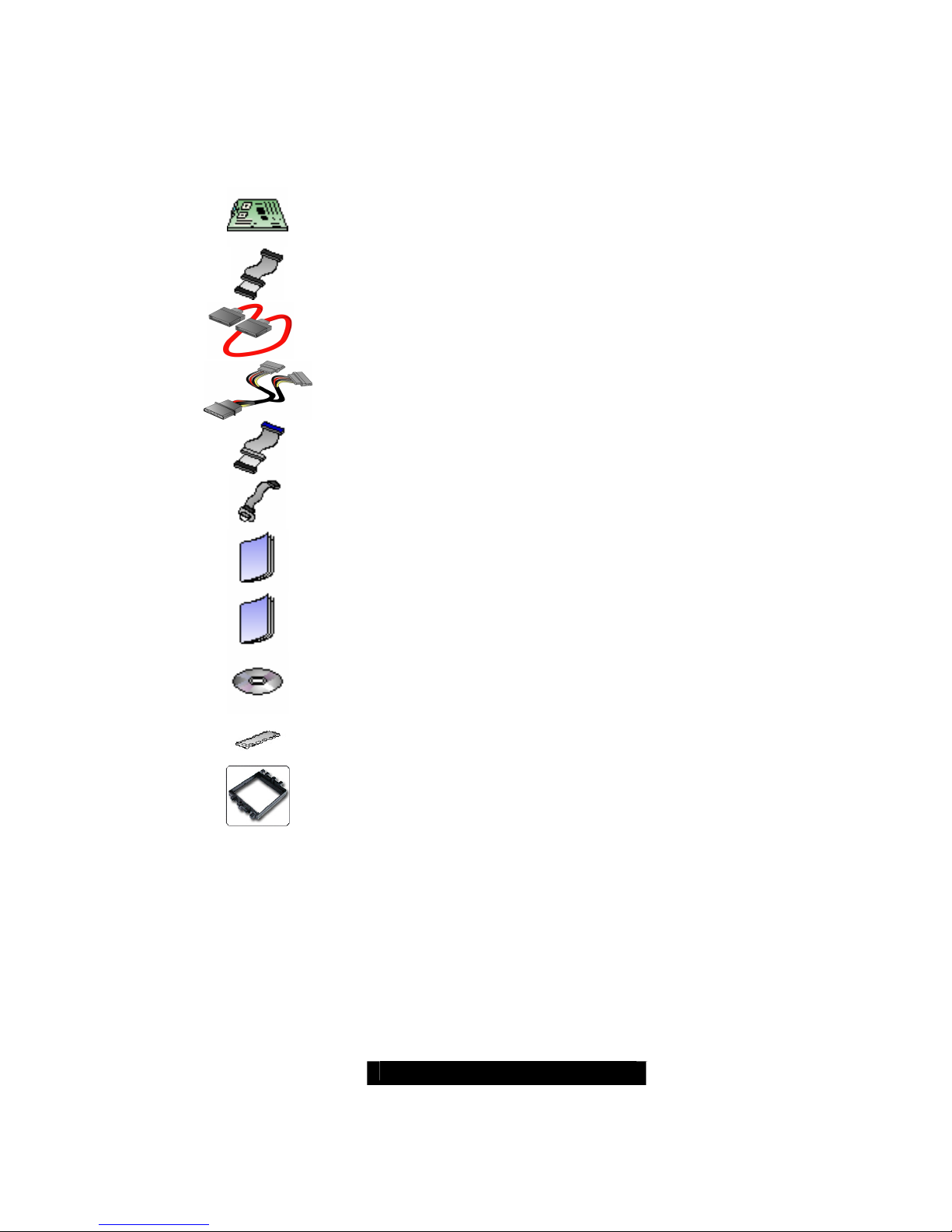
Check the box contents!
The retail motherboard package should contain the following:
1x Thunder K8QE motherboard
1x 34-Pin floppy drive cable
4 x SATA cable
2x SATA Drive Power Adapter
2x Ultra-DMA-100/66 IDE cable
1x Cable set: 9-pin Serial and 25-pin Parallel
1x Thunder K8QE user’s manual
1x Thunder K8QE Quick Reference guide
1x TYAN driver CD
1x I/O shield with 2 LAN ports
4 x CPU Mounting Kit
If any of these items are missing, please contact your vendor/dealer for replacement
before continuing with the installation process.

http://www.TYAN.com
5
Chapter 1: Introduction
Congratulations
You are now the owner of the ideal solution for rackmount servers, large computer
clusters, or pedestal server needs. The Tyan Thunder K8QE features support for Quad
AMD Opteron processors, dual channel Gigabit Ethernet, Serial ATA (SATAII).The
Thunder K8QE also offers the option to upgrade to eight-level processing capabilities
through use of HT4881 and M4881 add-on modules.
Remember to visit TYAN’s Website at http://www.TYAN.com
. There you can find
information on all of TYAN’s products with FAQs, online manuals and BIOS upgrades.
Hardware Specifications
Processor
Quad PGA 940 -pin ZIF sockets
Supports up to four Single/Dual Core AMD
Opteron
TM
800 series processors
Four onboard 4-phase VRMs
Chipset
NVIDIA nForce Professional 2200
(CK804pro)
NVIDIA nForce Professional 2050 (IO4)
Winbond W83627HF Super I/O
Three Analog Devices ADT7476 Hardware
Monitoring IC
Memory
128-bit dual channel memory bus
Sixteen 184-pin DDR DIMM sockets (Four
per CPU)
Supports up to 64GB Registered DDR
Memory
Supports ECC type memory modules
Supports DDR400, DDR333, or DDR266
Supports Single, Dual and Quad Rank
Memory
Expansion Slots
Two x16 PCI Express slots with x16 signal
Two x16 PCI Express slots with x4 signal
One 32bit/33MHz PCI v2.3 slot
Total of five usable slots
Integrated ATA-133
Two ATA-133 Channels for up to four ATA133 devices
Integrated SATA Controllers
Four Integrated dual port SATAII
Controllers (Two from CK804 Pro and two
from IO4)
Supports up to eight SATAII drives
Supports up to 3.0Gb/s
Supports 4 independent SATAII ports
Supports Raid 0, 1, 0+1
Integrated I/O
One floppy connector supports up to two
drives
One parallel port header and two serial
ports (one connector, one header)
Six USB 2.0 EHCI ports (two rear port
connectors & 2x 2 port headers)
PS/2 mouse and keyboard connectors
System Management
Modular BMC 2 x 25-pin header for SMDC
support
Six 4-pin fan headers support tachometer
monitoring and smart FAN control (PWM)
Four 3-pin fan headers support tachometer
monitoring
Temperature and voltage monitoring
Port 80h LED display
Integrated Video Controller
XGI XG20
PCI interface
16MB DDR memory

http://www.TYAN.com
6
Intelligent Platform Management
Interface Header
Tyan Server Management Daughter card
(Optional) support via IPMI header
Renesas Baseboard Management
Controller (BMC) tailored for IPMI 2.0 Spec
Supports KCS and BT styles
Flexible Windows or Linux Management
Solution
Supports RMCP and SNMP protocols
Supports ASF standard and EMP
I2C serial multi-master controllers and
UARTs
Built-in IPMB connector
Remote power on/off and reset support
(IPMI-over- LAN)
Hyper Transport™ Connectors
Two PCI Express x16 slots with TYAN
private signal definition which uses the
Hyper Transport to connect two HT cards
to the M4881. (CPU Board specifically
designed by TYAN).
Integrated LAN Controllers
Two Marvell® 88E1111 GbE PHY
• Each one has RJ-45 LAN connector with
LEDs
• Each one has front panel LED header
One Intel 82541 GbE LAN controller
• RJ-45 LAN connector with LED
BIOS
PhoenixBIOS® on 8Mbit LPC Flash ROM
ACPI 2.0
Serial Console Redirect
USB device boot
48-bit LBA Support
Power management:S0, S1, S4 and S5
Form Factor
SSI MEB Footprint (13”x16”)
EPS12V/SSI v3.5(24 + 8 + 8) power
connectors
Serial (one) connectors and one VGA port
Stacked USB 2.0 connectors
Stacked PS/2 keyboard and mouse
connectors
Three RJ-45 LAN connector with LEDs
Power Supply
EPS12V Power Supply
*Not validated at the time of print, subject
to change.
Software Specifications
OS (Operating System) Support:
Microsoft Windows 2003 Enterprise Server(32/64-bit)
Microsoft Windows 2003 Server (32/64 bit)
RHEL 4 Update 1 64-bit
SuSE Enterprise 9.0 SP2 64bit
SuSE 10.0 64-bit
Other distributions of Linux pending validation
TYAN reserves the right to add support or discontinue support for any OS with or
without notice.

http://www.TYAN.com
7
Chapter 2: Board Installation
Precaution: The Thunder K8QE supports EPS12V power supplies (24-pin/8-pin) and will
not operate with any other types.
DO NOT USE ATX 2.x, ATX12V or ATXGES power supplies as they will damage the
board and void your warranty.
How to install our products right… the first time
The first thing you should do is read this user’s manual. It contains important information
that will make configuration and setup much easier. Here are some precautions you
should take when installing your motherboard:
(1) Ground yourself properly before removing your motherboard from the antistatic
bag. Unplug the power from your computer power supply and then touch a
safely grounded object to release static charge (i.e. power suppl y ca se). Fo r th e
safest conditions, TYAN recommends wearing a static safety wrist strap.
(2) Hold the motherboard by its edges and do not touch the bottom of the board, or
flex the board in any way.
(3) Avoid touching the motherboard components, IC chips, connectors, memory
modules, and leads.
(4) Place the motherboard on a grounded antistatic surface or on the antistatic bag
that the board was shipped in.
(5) Inspect the board for damage.
The following pages include details on how to install your motherboard into your chassis,
as well as installing the processor, memory, disk drives and cables.
NOTE DO NOT APPLY POWER TO THE BOARD IF IT HAS BEEN DAMAGED

http://www.TYAN.com
8
2.00 – Board Image
This picture is representative of the latest boar d revision available at the time of
publishing. The board you receive may or may not look exactl y like the above
picture.
The following page includes details on the vital components of this motherboard.
http://www.TYAN.com
9
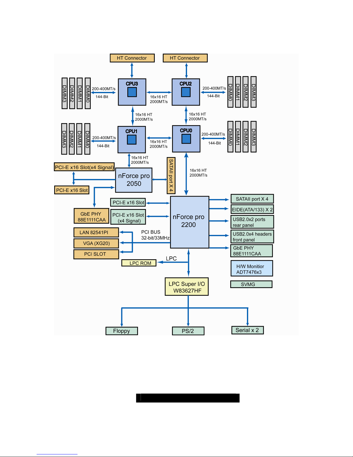
2.01 – Block Diagram
S4885 Thunder K8QE Block Diagram
Note: The Hyper Transport speed between HT CON & CPU can reach up to 2000MT/S
http://www.TYAN.com
10
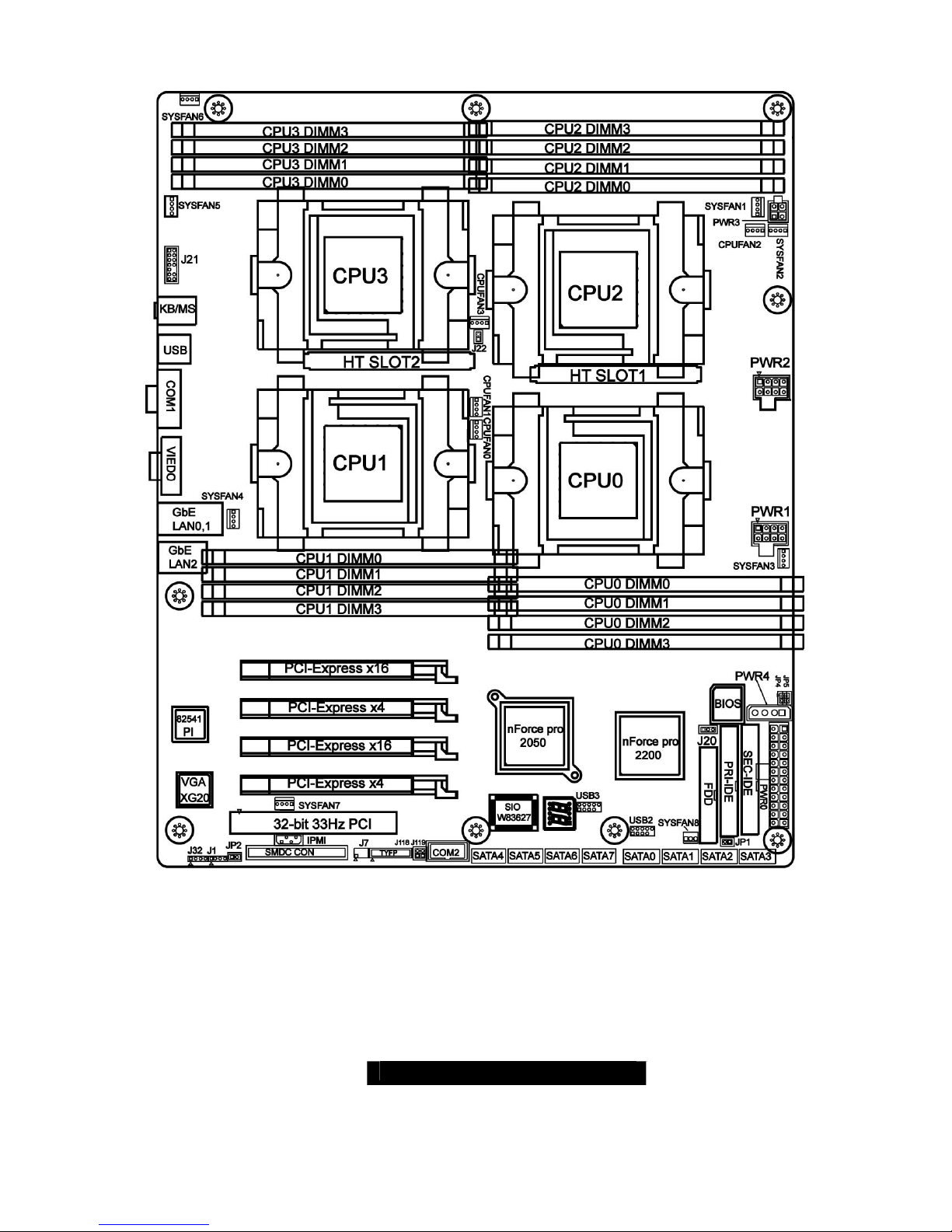
2.02 – Board Parts, Jumpers and Connectors
This diagram is representative of the latest board revision available at the time of
publishing. The board you receive may not look exactly like the above diagram.
http://www.TYAN.com
11
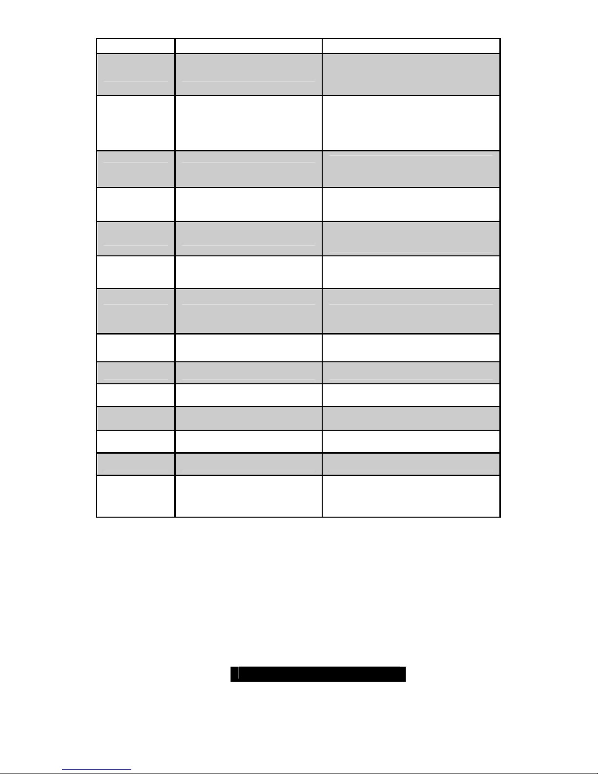
Function Settings
J115
Front Panel Connector
See Section 2.03 for pin out
configuration
J20
Clear CMOS Jumper
Close Pin-2 and Pin-3 (Default)
Normal mode
Close Pin-1 and Pin-2
Clear CMOS mode
J1
SMBus Connector
See Section 2.05 for pinout
configuration
J30, J95
USB 2.0 Header
For front or rear chassis USB
connectors
JP2
Chassis intrusion
See Section 2.07 for pin out
configuration
J101
Serial Port Internal
Header
See Section 2.08 for pin out
configuration
JP1
RI Header For external Wake on Ring
JP4, JP5
Gigabit LAN1, LAN2 LED
Header
See Section 2.10 for pin out
J118, J119
ID Switch & ID LED See Section 2.11, 2.12
J22
NMI See Section 2.13
CPU Fan Connectors See Section 2.14
System Fan Connectors See Section 2.15, 2.16
J32
EXT_SCSI_LED See Section 2.17
PWR CON See Section 2.18, 2.19
http://www.TYAN.com
12
Jumper Legend
OPEN - Jumper OFF Without jumper cover
CLOSED - Jumper ON With jumper cover
To indicate the location of pin-1
To indicate the location of pin-1
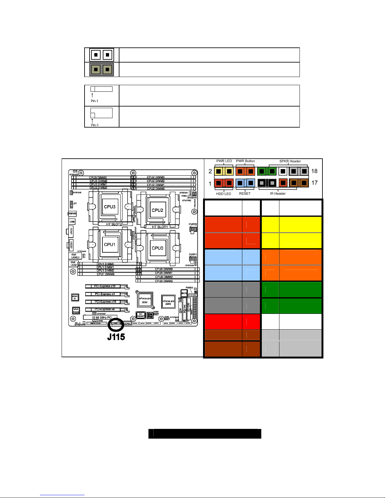
2.03 – Front Panel Connector (J115)
Function
PIN # PIN
#
Function
HDD
LED+
1 2 PWR LED+
HDD
LED-
3 4 PWR LED-
Reset
Button -
5 6
PWR
Button+
Reset
Button +
7 8 PWR Button-
VCC 9 10 NC
IRRX 11 12 VCC
GND 13 14 KEY
IRTX 15 16 GND
NC 17 18 SPKR

http://www.TYAN.com
13
2.04 – Clear CMOS Jumper (J20)
Pin_3 Pin_
1
Clear
Pin_3 Pin_
1
Default
You can reset the CMOS settings by
using this jumper or if you have
forgotten your system/setup
password and need to clear the
system BIOS settings.
- Power off system and disconnect
both power connectors from the
motherboard
- Use jumper cap to close Pin_1 and
Pin_2 for several seconds to Clear
CMOS
- Put jumper cap back to Pin_2 and
Pin_3 (default setting)
- Reconnect power & power on
system
2.05 – SMBus Connector (J1)
Pin_1
Pin_1:
SMBus
data
Pin_2
: NA
Pin_3:
SMBus
Clock
Pin_4:
NA
Use this connector to connect
external SMBUS devices
http://www.TYAN.com
14
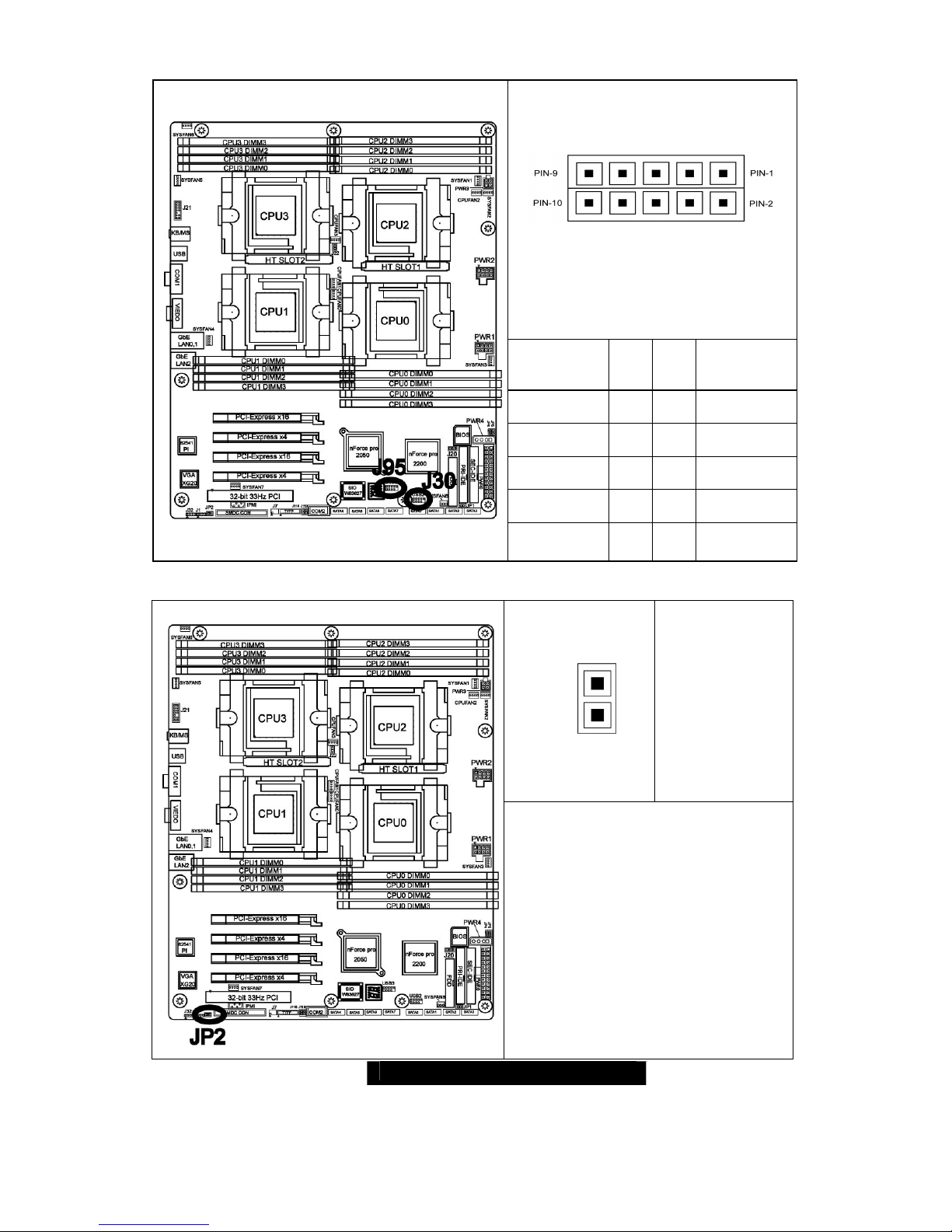
2.06 – USB 2.0 Header (J30, J95)
Signal
Descriptio
n
Pi
n #Pin #
Signal
Descriptio
n
VCC 1 2 VCC
USB DAT A- 3 4 USB DATA -
USB DAT A+ 5 6 USB DAT A+
GND 7 8 GND
KEY 9 10 NC
2.07 – Chassis intrusion (JP2)
PIN2
PIN1
Pin-2
GND
Pin-1
INTRUDUER_L
For use with chassis that support
this feature
http://www.TYAN.com
15
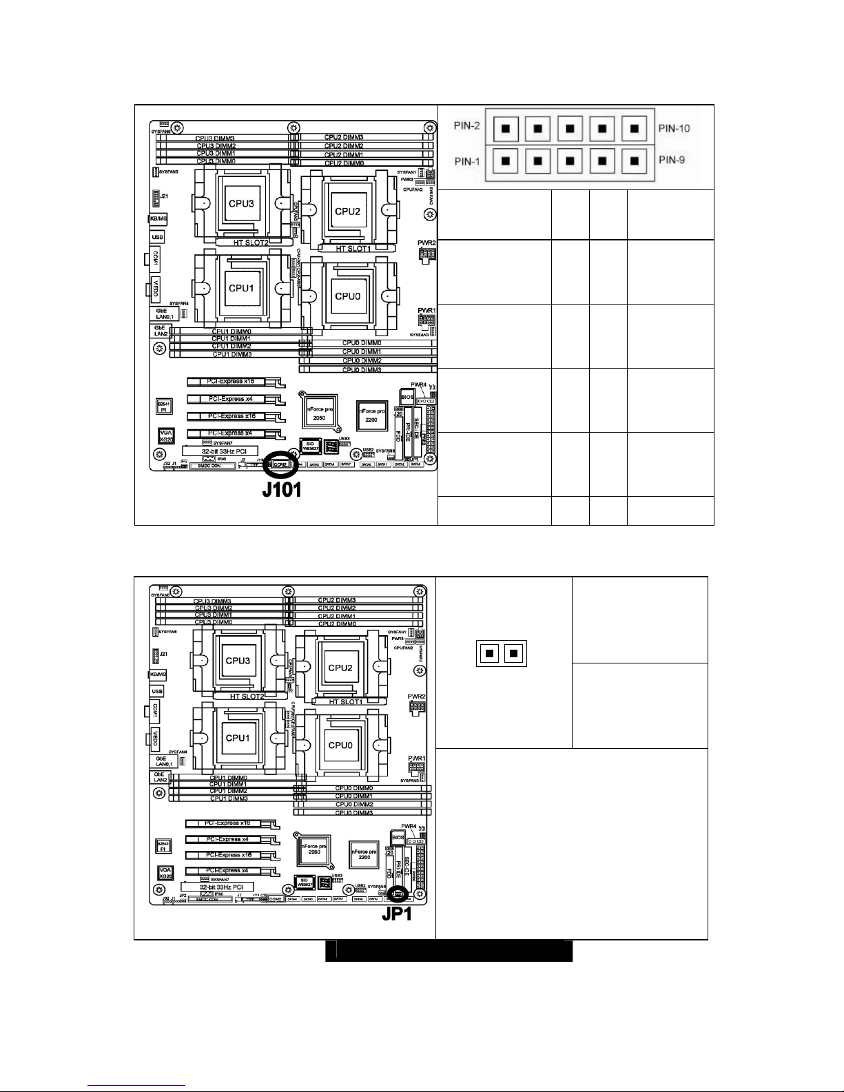
2.08 – COM2 Header (J101)
Signal
Description
Pi
n #Pin #
Signal
Descriptio
n
DCD2_L_SER
(Data Carrier
Detect)
1 2
DSR2_L_
SER
(Data-SetReady)
RXD2_SER(R
eceive-Data)
3 4
RTS2_L_
SER(Requ
est-toSend)
TXD2_SER(Tr
ansfer-Data)
5 6
CTS2_L_
SER(Clear
-to-Send)
DTR2_L_SER(
Data-TerminalReady)
7 8
RI2_L_SE
R(RingIndicator)
GND (Ground)
9 10
Key
2.09 – RI Header (JP1)
Pin 1: 5VSB
PIN-2 PIN-1
Pin 2: RI signal
JP1 is Wake on Ring PIN Header
http://www.TYAN.com
16
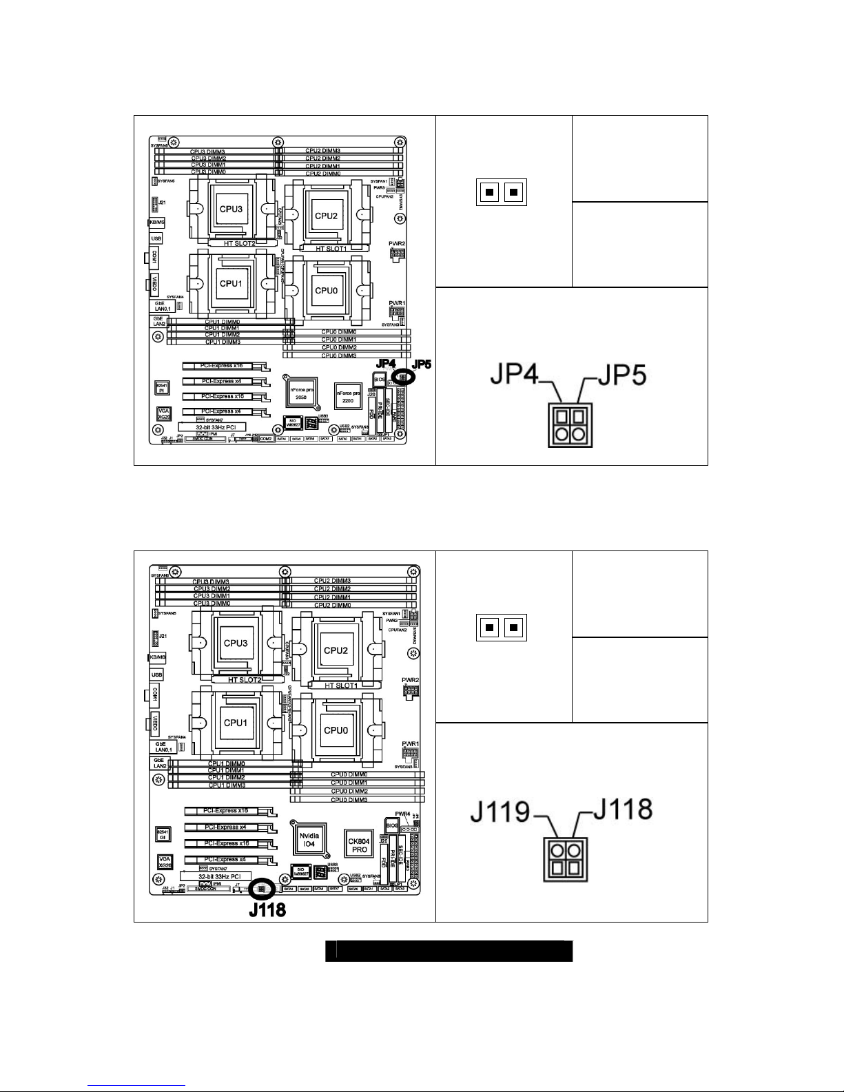
2. 10 – GbE LAN1,LAN2 LED Header (JP4, JP5)
Pin_1:LAN LED+
PIN-1 PIN-2
Pin_2:LAN LED-
Use this 2-pin header to connect LAN
LED on front panel.
2.11 – ID Switch (J118)
Pin_1:5VSB
PIN-1 PIN-2
Pin_2:Switch
signal-
Use to turn on and turn off ID LED
http://www.TYAN.com
17
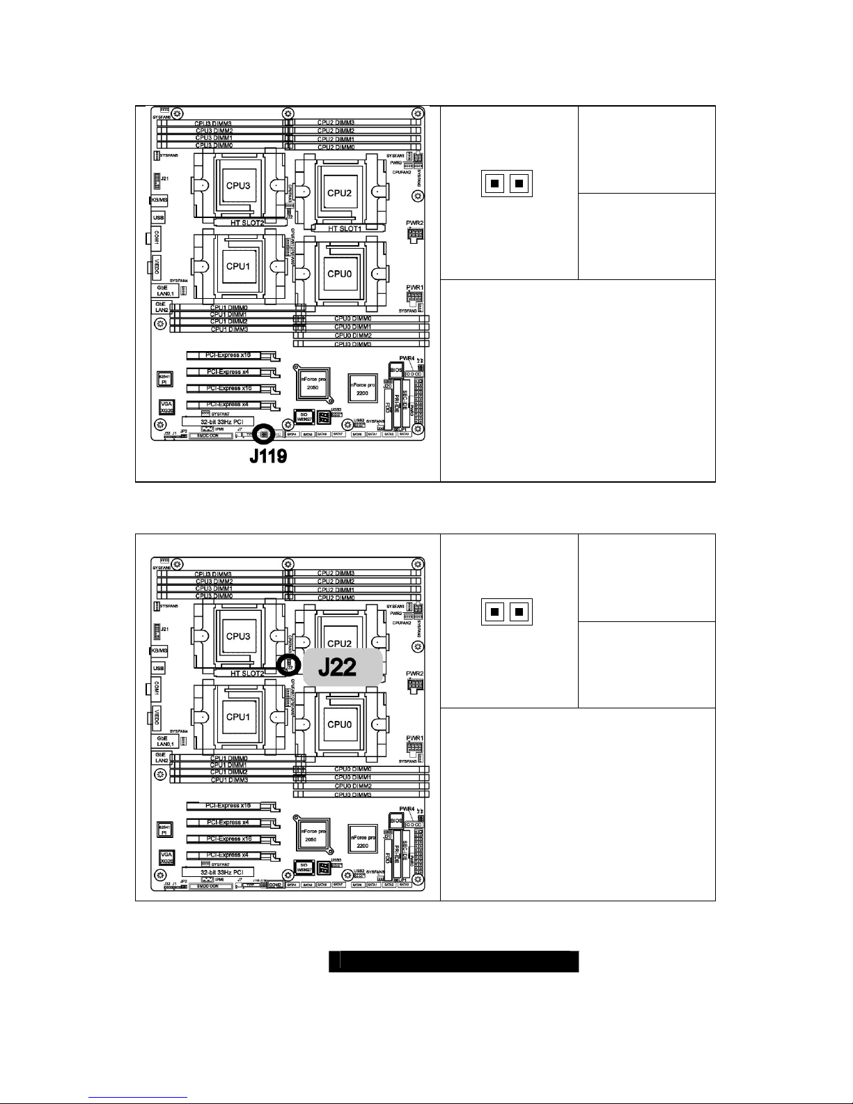
2.12 – ID LED (J119)
Pin_1:Turn on/off
signal
PIN-1 PIN-2
Pin_2:GND
The ID LED is used to help identify a
system for servicing when it is
installed within a high density rack or
cabinet that is populated with several
other similar systems.
The first press of the ID Switch will
turn on the LED, and the second press
will turn off ID LED.
2.13 – NMI (J22)
Pin_1:NMI Signal
PIN-1 PIN-2
Pin_2:3.3VSB
Allows you to issue a non-maskable
interrupt.

http://www.TYAN.com
18
2.14 – CPU FAN Connectors (J117, J116, J108, J109)
#
FAN
Description
Functi
on
Amp
Rated
(Maximum
)
J11
7
CPUFAN0
RPM
Read
2.0 A
J11
6
CPUFAN1
RPM
Read
2.0 A
J10
8
CPUFAN2
RPM
Read
2.0 A
J10
9
CPUFAN3
RPM
Read
2.0 A
2.15 – Chassis 4PIN FAN Connectors (J103, J104, J105, J106, J107, J110)
#
FAN
Description
Function
Amp Rated
(Maximum)
J103 SYSFAN1 Read 2.0 A
J107 SYSFAN2 Read 2.0 A
J105 SYSFAN3 Read 2.0 A
J110 SYSFAN4 Read 2.0 A
J106 SYSFAN5 Read 2.0 A
J104 SYSFAN6 Read 2.0 A
http://www.TYAN.com
19
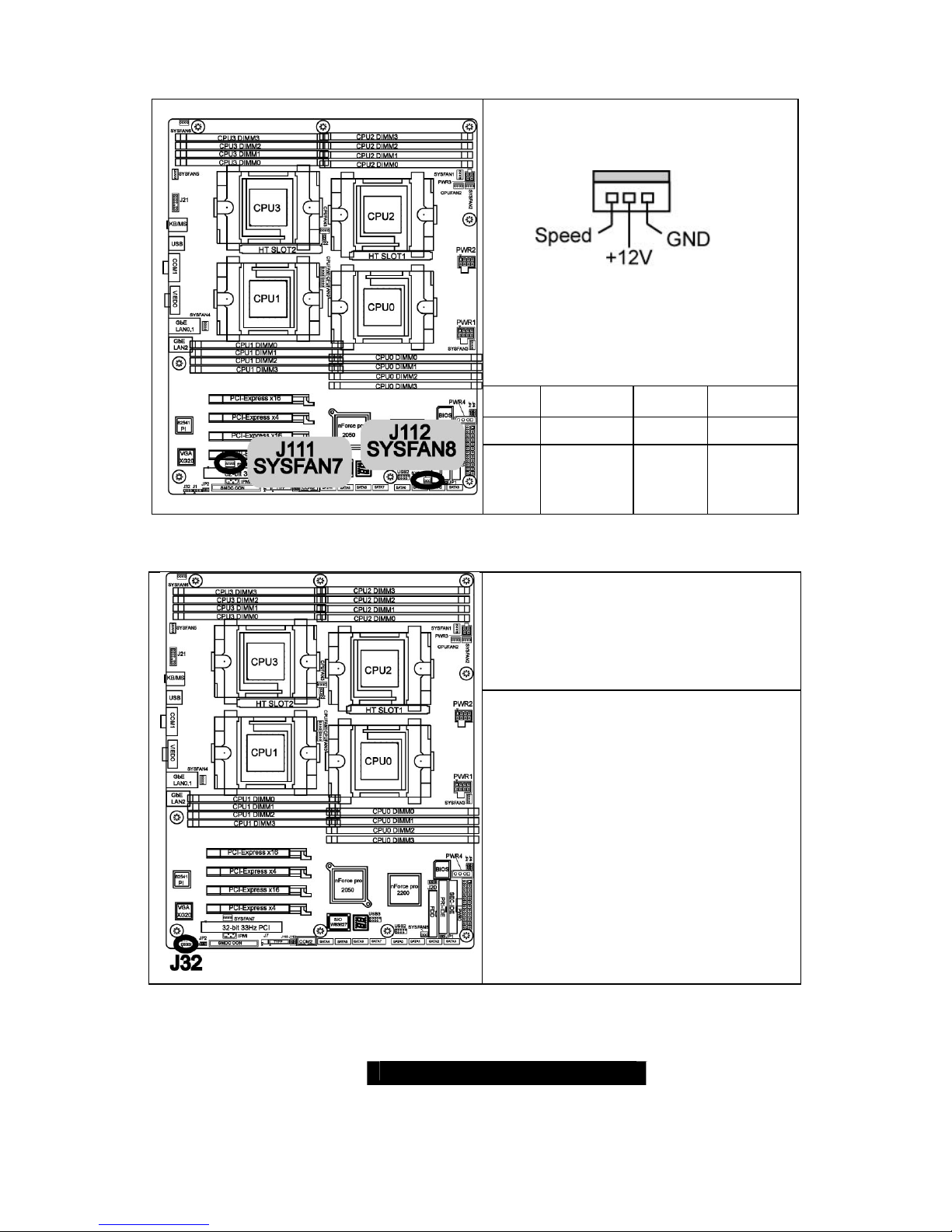
2.16 – Chassis 3PIN FAN Connectors (J111, J112)
#
FAN
Description
Function
Amp Rated
(Maximum)
J111 SYSFAN7 Read 1.6 A
J112 SYSFAN8 Read 1.6 A
2.17 – EXT_SCSI_LED(J32)
Use to connect for external SCSI LED’s
http://www.TYAN.com
20
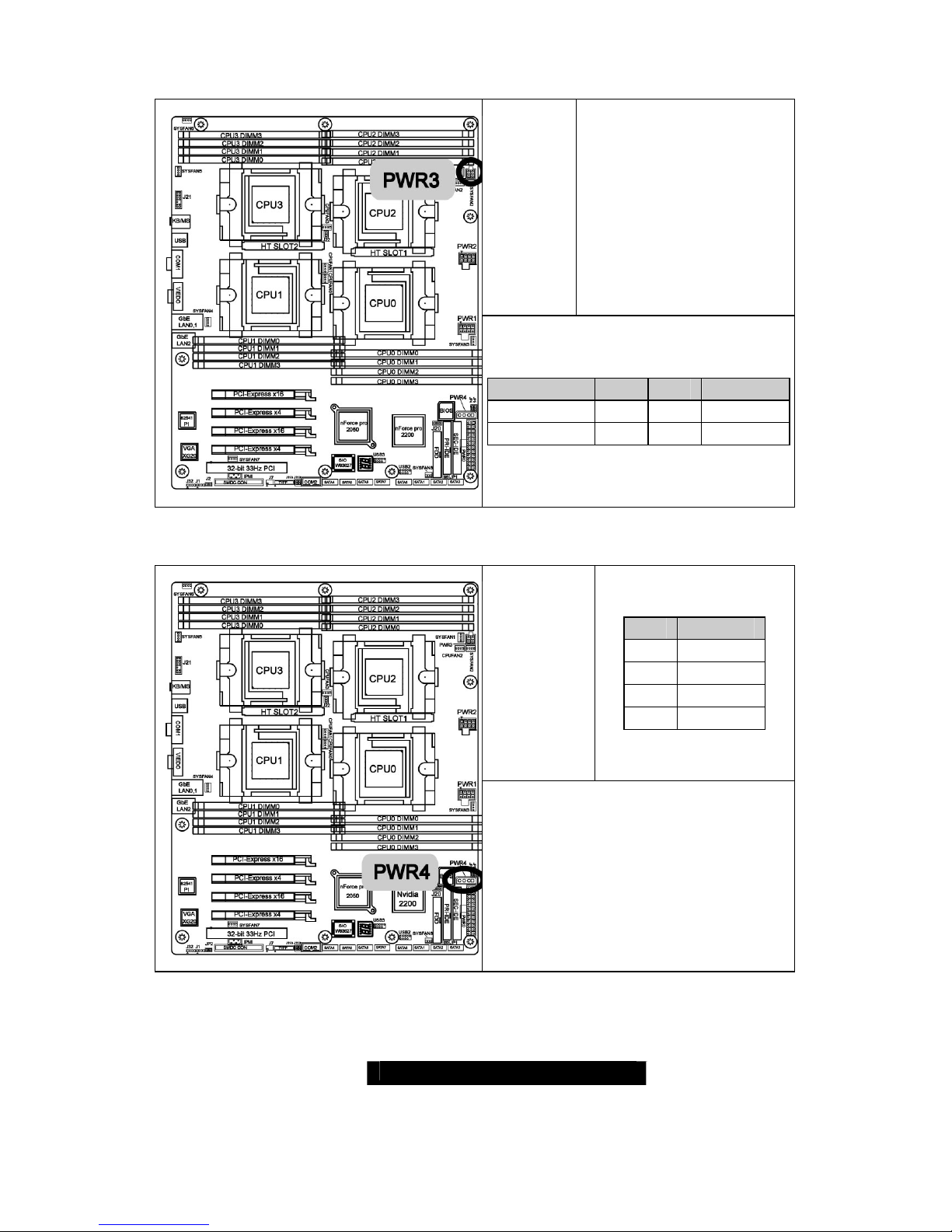
2.18 – PWR CON (PWR3)
ATX 12V power connector
This power connector
should be plugged when
using Quad Rank memory
Signal Pin Pin Signal
GND 1 3 12V
GND 2 4 12V
2.19 – PWR CON (PWR4)
Pin Signal
1 12V
2 GND
3 GND
4 5V
1 X 4-Pin 5V power connector
This power connector should be
plugged when using Quad Rank
memory
http://www.TYAN.com
21
2.20 – OEM Reserved Connectors and Jumpers
The connectors and jumpers, which are not listed, are reserved for OEM use only.
2.21– Installing the Processor(s)
Your brand new Thunder K8QE supports the latest 64-bit processor technologies from
AMD. Only AMD Opteron
™
processor 800 series are certified and supported with this
motherboard.
Check our website for latest processor support. http://www.tyan.com
NOTE If using a single processor, it MUST be installed in socket CPU0.
When using a single processor only CPU0 memory banks are
addressable.
TYAN is not liable for damage as a result of operating an unsupported configuration.
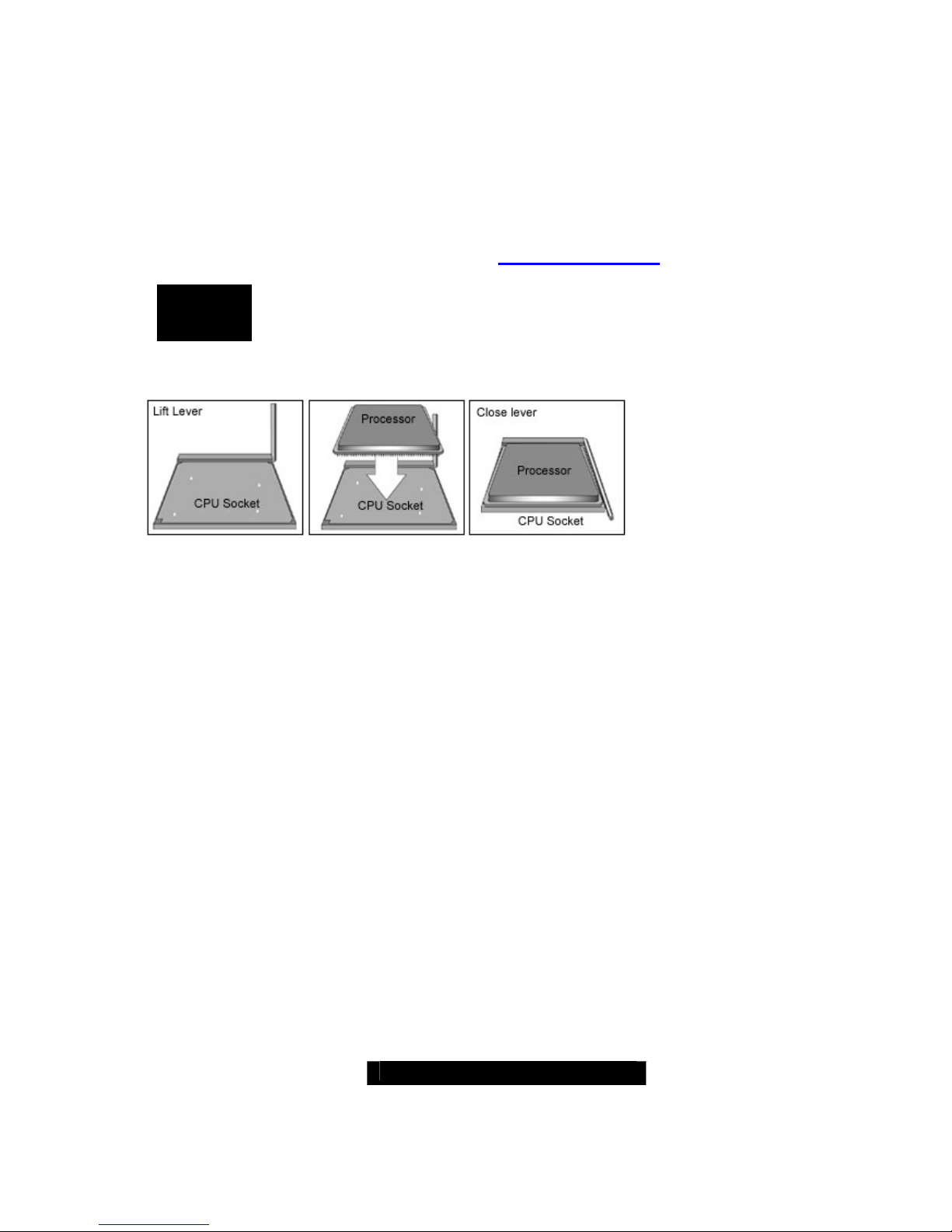
The diagram is provided as a visual guide to help you install socket processors and may
not be an exact representation of the processors you have.
Lift the lever on the socket until it is approximately 90
o
or as far back as possible to the
socket.
Align the processor with the socket. There are keyed pins underneath the processor to
ensure that the processor’s installed correctly.
Seat the processor firmly into the socket by gently pressing down until the processor sits
flush with the socket.
Place the socket lever back down until it locks into place.
Your processor is installed.
Repeat these steps for the second, third and fourth processor if you are using four
processors.
Take care when installing processors as they have very fragile connector pins below the
processor and can bend and break if inserted improperly.
http://www.TYAN.com
22
2.22 - Heatsink Retention Frame Installation
After you are done installing the processor(s), you should proceed to installing the
retention frame and heatsink. The CPU heatsink will ensure that the processors do not
overheat and continue to operate at maximum performance for as long as you own them.
Overheated processors are also dangerous to the health of the motherboard.
The backplate assembly prevents excessive motherboard flexing in the area near the
processor and provides a base for the installation of the heatsink retention bracket and
heatsink.
Because there are many different types of heatsinks available from many different
manufacturers, a lot of them have their own method of installation. For the safest method
of installation and information on choosing the appropriate heatsink, use heatsinks
validated by AMD. Please refer to AMD’s website at www.amd.com
.
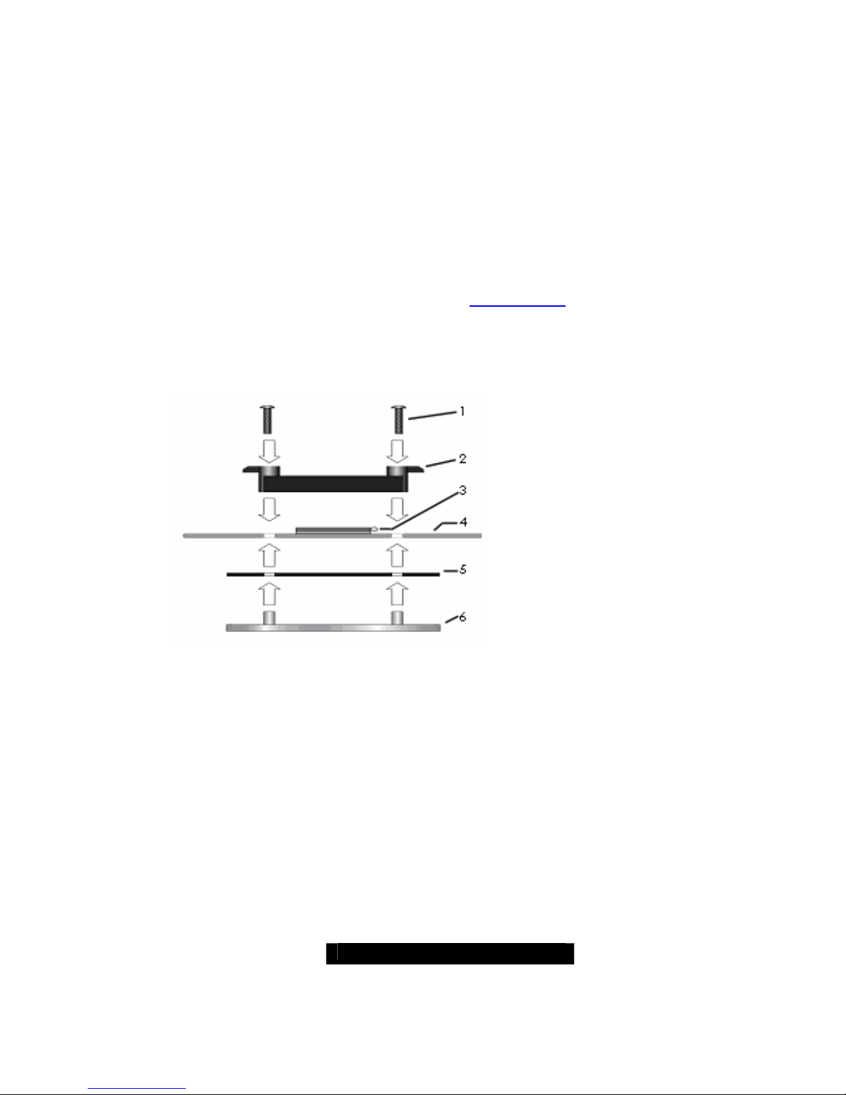
The following diagram will illustrate how to install the most common CPU back
plates:
1. Mounting screws
2. Heatsink retention frame
3. CPU socket
4. Motherboard PCB
5. Adhesive insulator material
6. Backplate assembly
NOTE: Please see next section
for specific instructions on how
to install mounting bracket.
http://www.TYAN.com
23
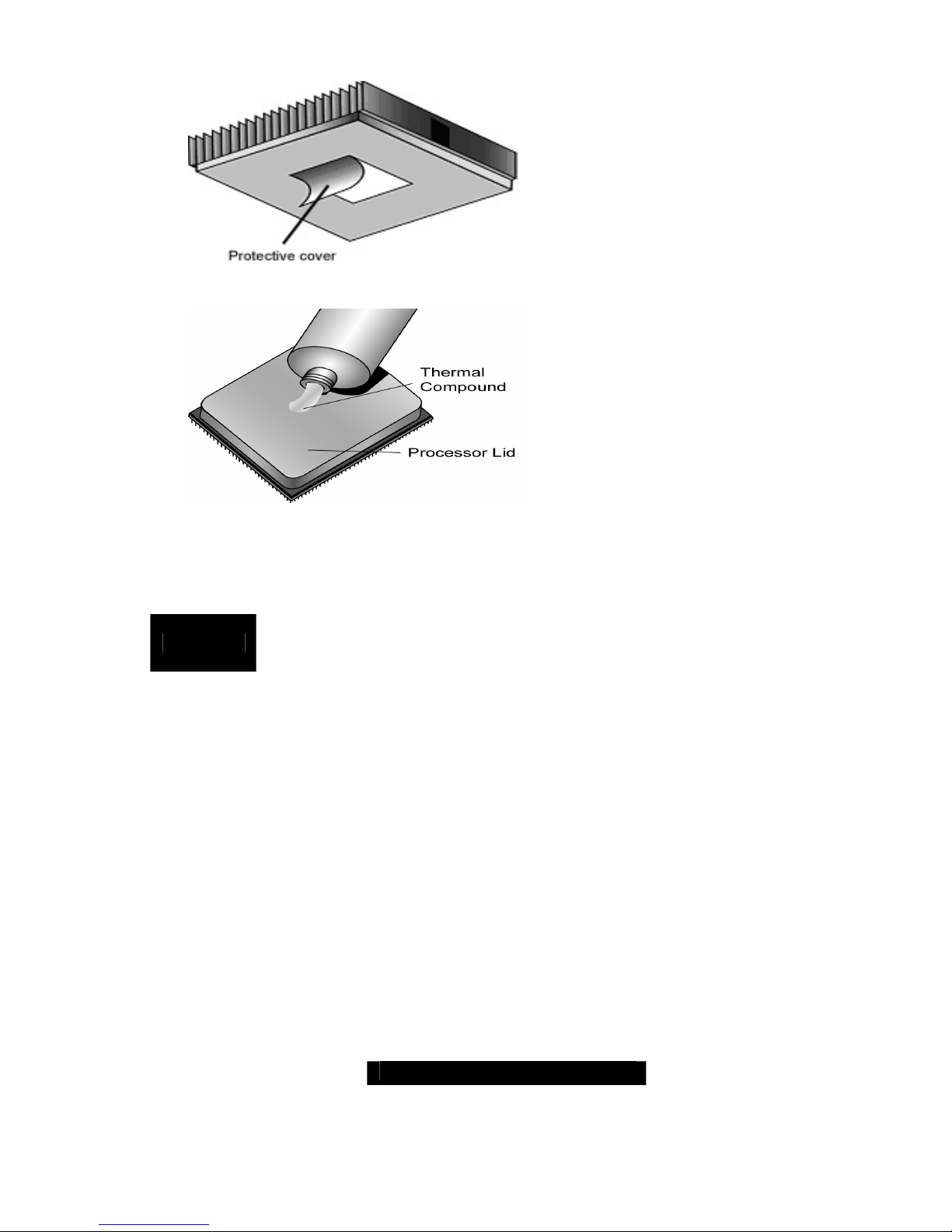
2.23 -- Thermal Interface Material
There are two types of thermal
interface materials designed for
use with the AMD Opteron
processor.
The most common material
comes as a small pad attached
to the heatsink at the time of
purchase. There should be a
protective cover over the
material. Take care not to touch
this material.
Simply remove the protective
cover and place the heatsink on
the processor.
The second type of interface
material is usually packaged
separately. It is commonly
referred to as ‘thermal
compound’. Simply apply a thin
layer on to the CPU lid (applying
too much will actually reduce the
cooling).
NOTE
Always check with the manufacturer of the heatsink & processor to
ensure the Thermal Interface material is compatible with the
processor & meets the manufacturer’s warranty requirements
 Loading...