

TYAN THUNDER TOMCAT H1000E, S3970 User Manual

http://www.tyan.com
1
Thunder h1000E
Tomcat h1000E
///
S3970
Version 1.1
Copyright
Copyright © TYAN Computer Corporation, 2006. All rights reserved. No part of
this manual may be reproduced or translated without prior written consent from
TYAN Computer Corp.
Trademark
All registered and unregistered trademarks and company names contained in
this manual are property of their respective owners including, but not limited to
the following.
TYAN, Taro and Thunder h1000E / Tomcat h1000E are trademarks of TYAN
Computer Corporation.
AMD, Opteron, and combinations thereof are trademarks of AMD Corporation.
Nvidia and nForce are trademarks of Nvidia Corporation
Microsoft, Windows are trademarks of Microsoft Corporation.
SuSE,is a trademark of Novell.
Linux is a trademark of Linus Torvalds
IBM, PC, AT, and PS/2 are trademarks of IBM Corporation.
Winbond is a trademark of Winbond Electronics Corporation.
Notice
Information contained in this document is furnished by TYAN Computer
Corporation and has been reviewed for accuracy and reliability prior to printing.
TYAN assumes no liability whatsoever, and disclaims any express or implied
warranty, relating to sale and/or use of TYAN products including liability or
warranties relating to fitness for a particular purpose or merchantability. TYAN
retains the right to make changes to product descriptions and/or specifications
at any time, without notice. In no event will TYAN be held liable for any direct or
indirect, incidental or consequential damage, loss of use, loss of data or other
malady resulting from errors or inaccuracies of information contained in this
document.

http://www.tyan.com
2
Table of Contents
Chapter 1: Introduction
1.1 Congratulations Page 5
1.2 Hardware Specifications Page 5
Chapter 2: Board Installation
2.1 Board Image Page 8
2.2 Block Diagram Page 9
2.3 Board Parts, Jumpers and Connectors Page 10
2.4 Tips on Installing Motherboard in Chassis Page 20
2.5 Installing the Processor(s) Page 21
2.6 Installing the Memory Page 26
2.7 Attaching Drive Cables Page 29
2.8 Installing Add-In Cards Page 31
2.9 Installing Optional SO-DIMM Modules Page 32
2.10 Connecting External Devices Page 33
2.11 Installing the Power Supply Page 34
2.12 Finishing Up Page 35
Chapter 3: BIOS
3.1 BIOS Setup Utility Page 37
3.2 BIOS Menu Bar Page 38
3.3 BIOS Legend Bar Page 38
3.4 BIOS Main Menu Page 40
3.5 BIOS Advanced Menu Page 41
3.6 BIOS PnP/PCI Menu Page 60
3.7 BIOS Boot Menu Page 62
3.8 BIOS Security Menu Page 67
3.9 BIOS Chipset Menu Page 68
3.10 BIOS Exit Menu Page 77
Chapter 4: Diagnostics
4.1 Beep Codes Page 79
4.2 Flash Utility Page 79
4.3 AMIBIOS Post Code Page 80
Appendix I: SMDC Information Page 83
Appendix II: How to Make a Driver Diskette Page 85
Glossary Page 87
Technical Support Page 93
http://www.tyan.com
3
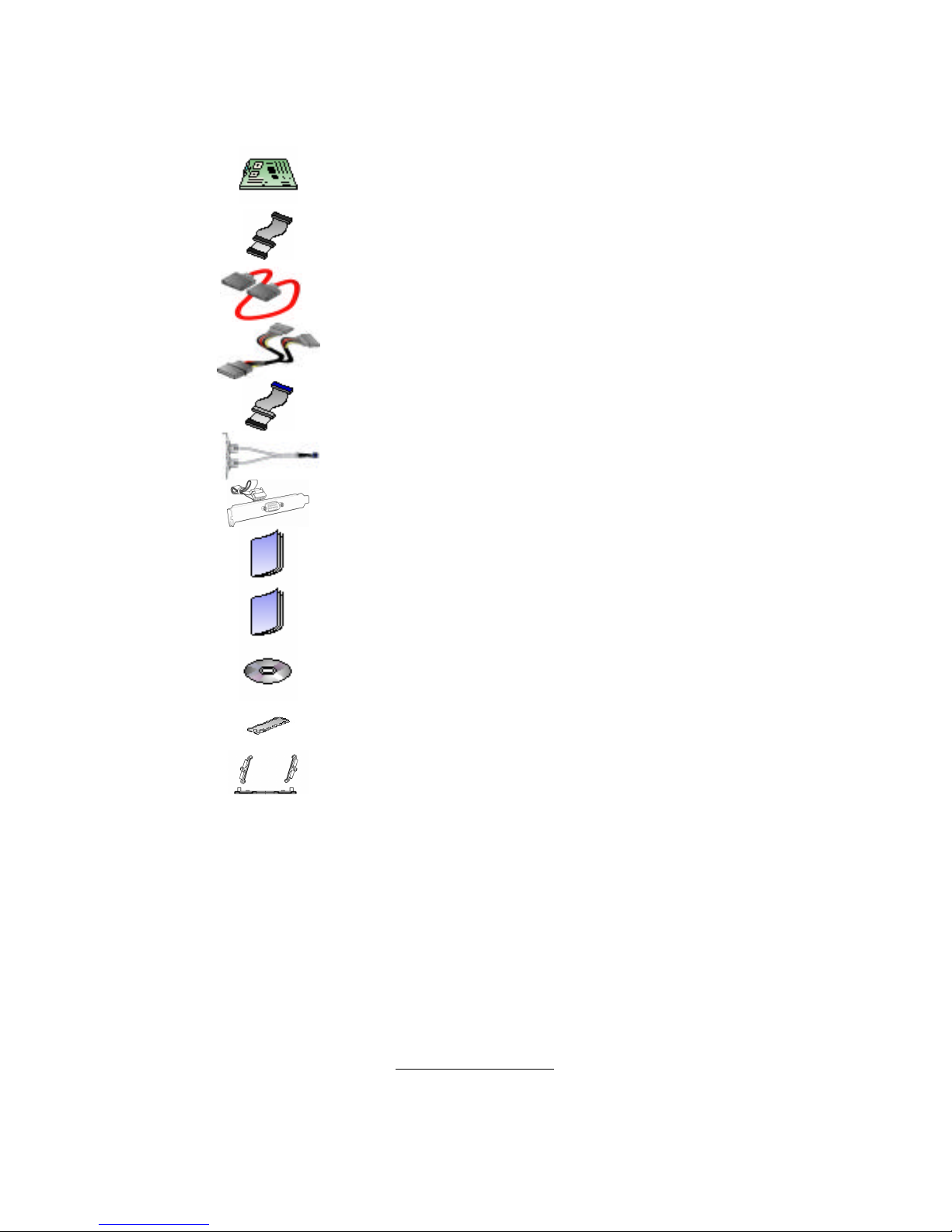
Check the box contents!
The retail motherboard package should contain the following:
1x Thunder h1000E / Tomcat h1000E
motherboard
1x 34-Pin floppy drive cable
4 x SATA cable
2 x SATA Drive Power Adapter
1 x Ultra-DMA-100/66 IDE cable
1 x USB2.0 cable
1 x COM Port cable
1 x Thunder h1000E / Tomcat h1000E
User’s Manual
1 x Thunder h1000E / Tomcat h1000E
Quick Reference Guide
1 x TYAN driver CD
1 x I/O shield
2 x CPU Retention Frame and Back Plate
(Thunder h1000E)
1x CPU Retention Frame and Back Plate
(Tomcat h1000E)
If any of these items are missing, please contact your vendor/dealer for
replacement before continuing with the installation process.

http://www.tyan.com
4
NOTE

http://www.tyan.com
5
Chapter 1: Introduction
1.1 - Congratulations
You have purchased one of the most powerful server solutions available. The
Thunder h1000E (S3970G2NR) / Tomcat h1000E (S3970G2N-U) S3970 is a
high-end server motherboard, based on the ServerWorks BCM5785 chipset. It
also includes the SMSC SCH4307 Super I/O and SMSC EMC6D103 Hardware
Monitoring chipsets.
This motherboard is designed to support up to two AMD® OpteronTM 2000
Series processors and DDRII 667/533 memory. The S3970 is ideal for CPU,
memory, and network intensive applications required in the HPC and clustering
environments.
Remember to visit TYAN’s Website at http://www.tyan.com. There you can find
information on all of TYAN’s products with FAQs, online manuals and BIOS
upgrades.
1.2 - Hardware Specifications
Processors
• Two uPGA 1207-pin ZIF sockets
• Integrated 144-bit DDR2 memory
controller
• Thunder h1000E --- supports dual
AMD® OpteronTM 2000 Series
processors
• Tomcat h1000E --- supports single
AMD® OpteronTM 2000 Series
processor
Chipset
• ServerWorks BCM5785 (HT1000)
core-logic
• SMSC SCH4307 Super I/O
System Management
• Two (2) SMSC EMC6D103 hardware
monitoring IC
• Four (4) 4-pin + two (2) 3-pin fan
headers support tachometer
monitoring, four (4-pin) of them with
smart FAN control
• Temperature and voltage monitoring
• Watchdog timer support
Optional Modules
• M3291, IPMI 2.0 Remote System
Mgmt card
- Renesas H8S2167 BMC controller
- BT, KCS, Logging support
- IPMI-over-LAN
- Remote power on/off and reset
• M7901/M7902, Ultra 320 SCSI TARO
card
- Adaptec AIC-7901/7902 single/dualchannel Ultra320 SCSI controller
- Adaptec Host RAID 0, 1, 10 supported
• M9000 SAS/SATA II TARO card
- Adaptec AIC-9405/9410 SAS
controller
- Supports up to 4-port (M9000-5) and
8-port (M9000-10) SAS & SATA running
at 1.5Gb/s or 3.0 Gb/s
- Adaptec Host RAID 0, 1 & 10
supported
Integrated SATA Controllers
• Supports four SATA ports at 1.5 Gb/s
with NCQ
• RAID 0/1//510 supported (Windows
and Linux support, Thunder h1000E
only)

http://www.tyan.com
6
Memory
• Dual channel memory bus
• Eight 240-pin DIMM sockets
• Registered, ECC DDRII module
supported, up to DDRII-667
Expansion Slots
• One PCI-X 64-bit 133/100MHz slot
• Four 32-it/33MHz PCI v2.3 slots
• One TYAN “TARO” SO-DIMM socket
• Total of six usable slots
Integrated I/O
• One floppy connector
• One IDE connector
• Four SATA connectors
• Four USB2.0 ports (2 at rear, 2 via
cable)
• Two COM ports (1 at rear, 1 via cable)
• Tyan 2 x 9 front panel pin header
• Tyan 2 x 6 pin header for front panel
LAN LED and ID LED/Switch
• 2 x 25 connector for optional TYAN
IPMI SMDC
Back Panel I/O Ports
• Stacked PS/2 Mouse & Keyboard
ports
• Stacked 2 USB ports
• One 9-pin COM port
• One 15-pin VGA connector
• Two side-by-side RJ-45 ports
Integrated Video Controller
• XGI Volari Z7 (XG20)
•16MB frame buffer memory
Integrated ATA-100
• One ATA Channel for up to two ATA-
100 devices
Integrated LAN Controllers
• Two Intel i82541 PI GbE LAN
controllers
- With ASF 2.0/WfM/Teaming support
- Operating on 32bit/33MHz PCI bus
BIOS
• AMI BIOS on 8Mbit LPC Flash ROM
• Serial Console Redirect
• USB boot support
• ACPI supported
• PnP, DMI2.0, WfM2.0 power
management
Form Factor
• ATX footprint
• 12” x 10.2” (304.8mm x 259.1mm)
Power
• Onboard dual 4-phase VRM
• EPS12V (24+8) power connectors
Regulatory
• FCC Class B (DoC)
• European Community CE (DoC)
• BSMI (optional)
http://www.tyan.com
7
Chapter 2: Board Installation
Precautions: The Thunder h1000E / Tomcat h1000E supports SSI, EPS12V
type power supplies (24pin + 8pin) and will not operate with any other types.
For proper power supply installation procedures see page 34.
DO NOT USE ATX 2.x or ATXGES power supplies as they will damage the
board and void your warranty.
How to install our products right… the first time
The first thing you should do is reading this user’s manual. It contains important
information that will make configuration and setup much easier. Here are some
precautions you should take when installing your motherboard:
(1) Ground yourself properly before removing your motherboard from the
antistatic bag. Unplug the power from your computer power supply and
then touch a safely grounded object to release static charge (i.e. power
supply case). For the safest conditions, TYAN recommends wearing a
static safety wrist strap.
(2) Hold the motherboard by its edges and do not touch the bottom of the
board, or flex the board in any way.
(3) Avoid touching the motherboard components, IC chips, connectors,
memory modules, and leads.
(4) Place the motherboard on a grounded antistatic surface or on the
antistatic bag that the board was shipped in.
(5) Inspect the board for damage.
The following pages include details on how to install your motherboard into your
chassis, as well as installing the processor, memory, disk drives and cables.
NOTE
DO NOT APPLY POWER TO THE BOARD IF IT HAS BEEN
DAMAGED.
http://www.tyan.com
8
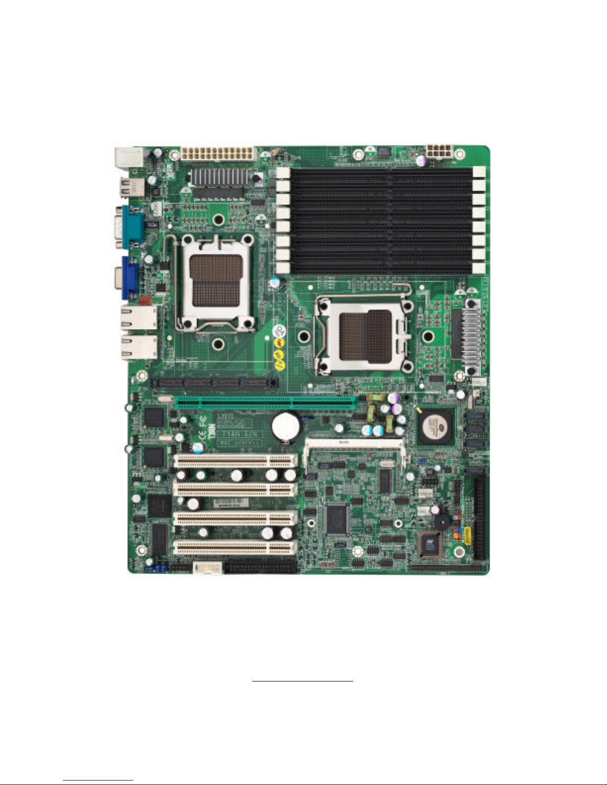
2.1- Board Image
This picture is representative of the latest board revision available at
the time of publishing. The board you receive may or may not look
exactly like the above picture.
The following page includes details on the vital components of this
motherboard.

http://www.tyan.com
9
2.2 - Block Diagram
Thunder h1000E / Tomcat h1000E Block Diagram
http://www.tyan.com
10
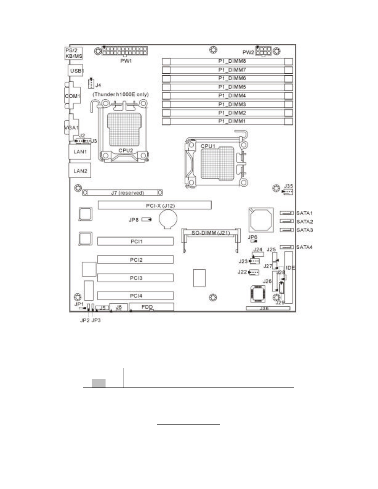
2.3 - Board Parts, Jumpers and Connectors
This diagram is representative of the latest board revision available at the time of
publishing. The board you receive may not look exactly like the above diagram.
Jumper Legend
©©
OPEN - Jumper OFF, without jumper cover
©©
CLOSED – Jumper ON, with jumper cover
http://www.tyan.com
11
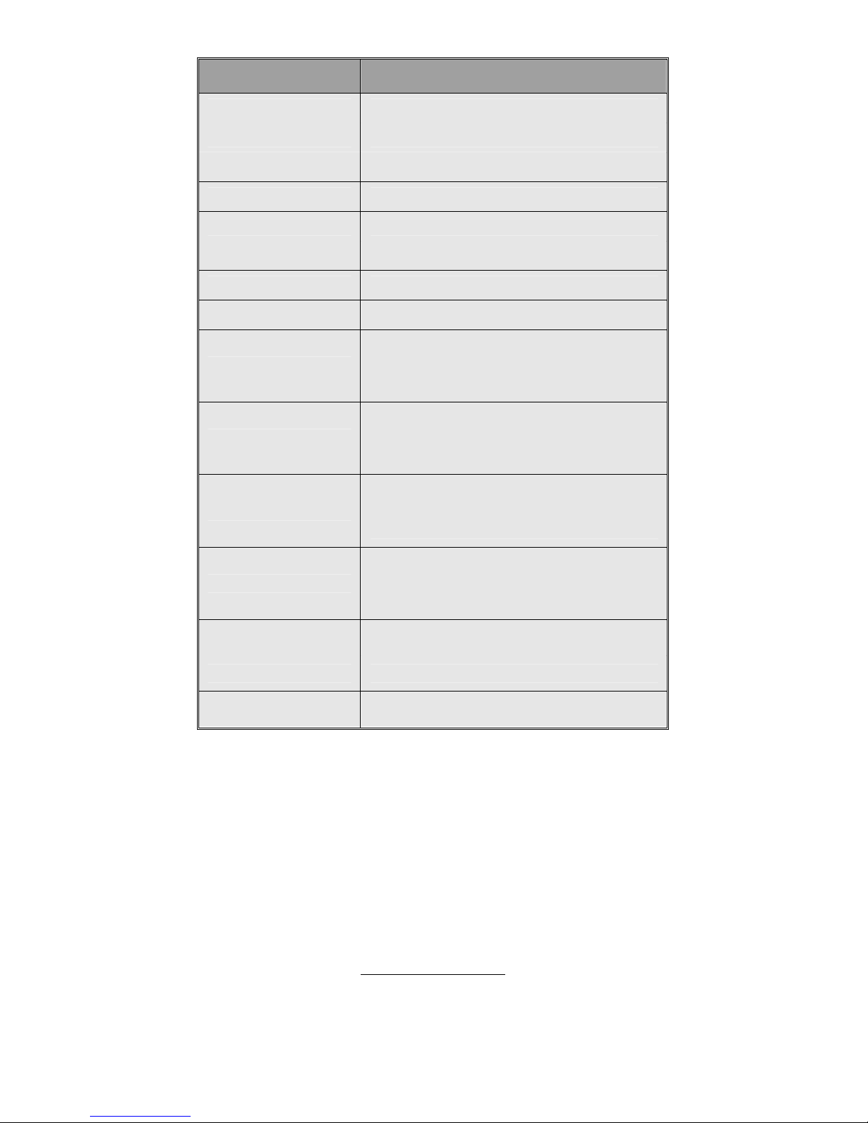
Jumper/Connector Function
J2/J3 3-pin Back Panel Fan Connector
J4/J22/J23/J35 4-pin Fan Connector with Speed Control
J6 COM2 Header
J24 USB Front Panel Connector
J25 Front Panel SATA LED Pin Header
J26 Front Panel Header
J27 LCM Pin Header
J29 IPMB Pin Header
JP1
VGA Enable/Disable Jumper
(Close 1-2) Default, enabled
(Close 2-3) Disabled
JP2/JP3
SMDC/ASF2.0 Select Jumper
(Close 1-2) Default, support ASF 2.0
(Close 2-3) support SMDC card
JP6
PCI-X Frequency Select Jumper
Open: 100MHz
Installed: Default, 133MHz
JP8
Clear CMOS Jumper
(Close 1-2) Default
(Close 2-3) Clear CMOS
J21 TARO SO-DIMM Socket
J36 SMDC Connector
J5/J28 Reserved for OEM only
http://www.tyan.com
12
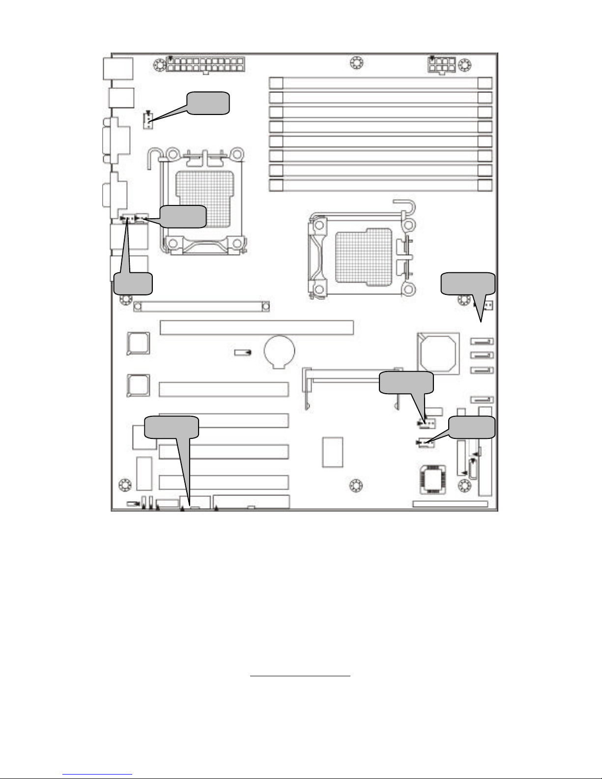
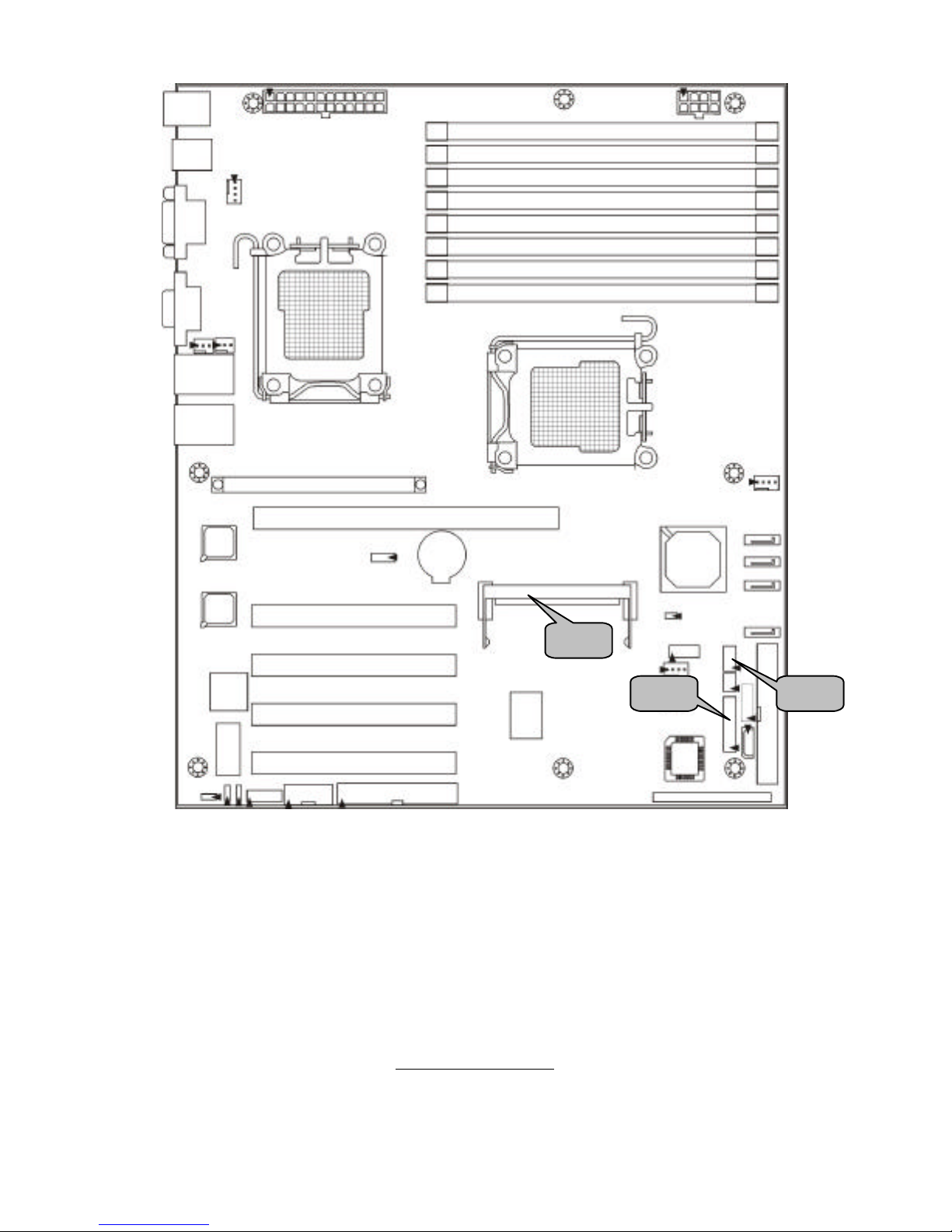
J22
J6
J2 J35 J4 J3 J23
http://www.tyan.com
13
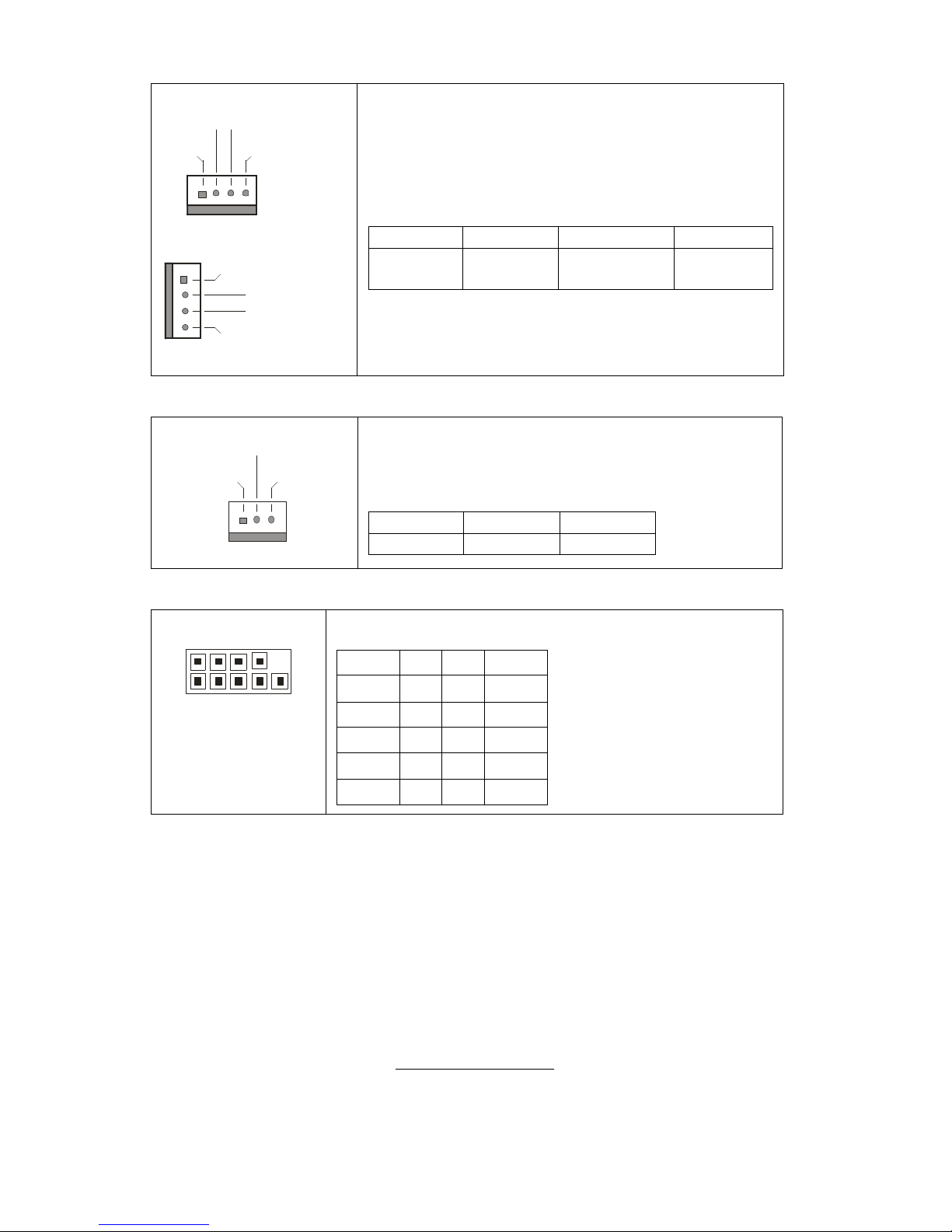
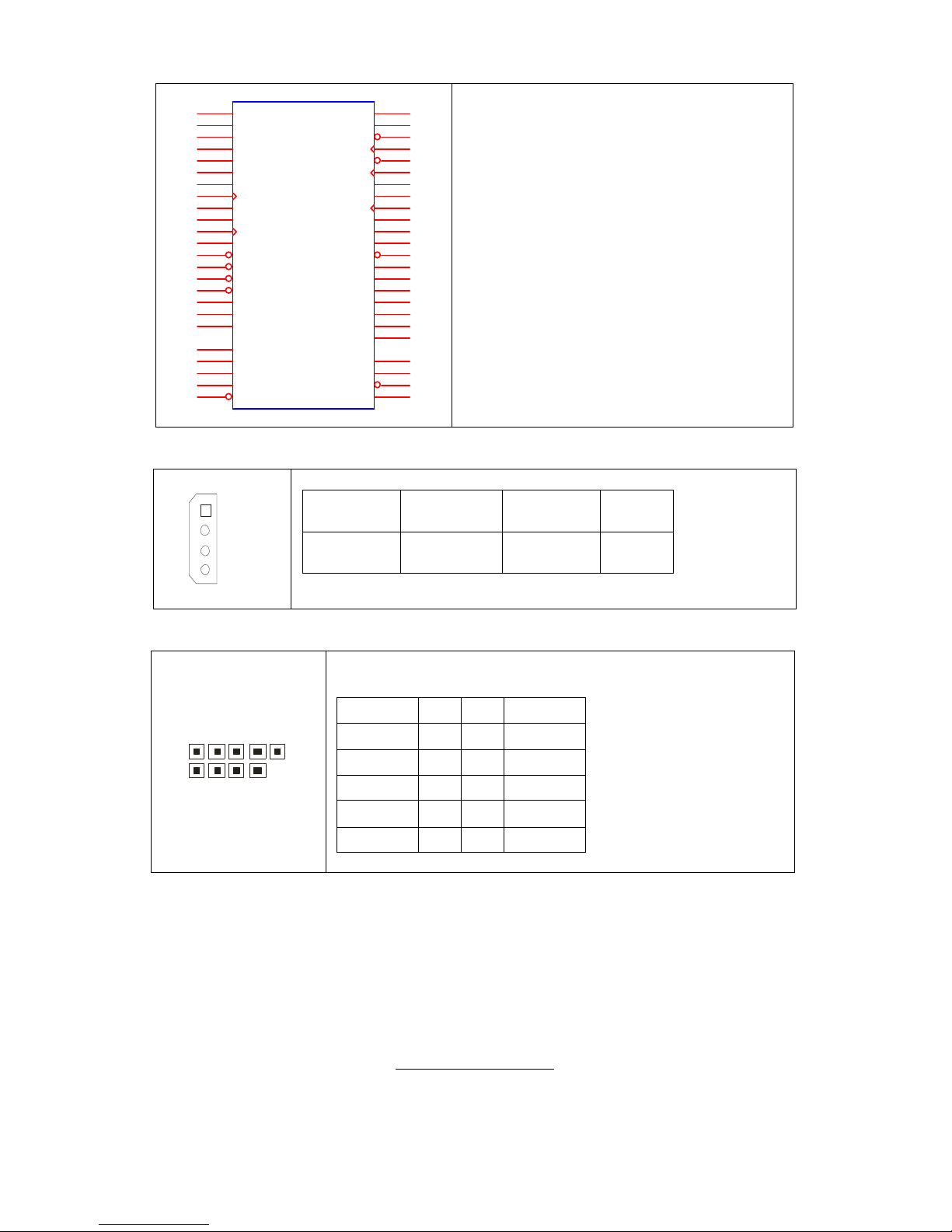
J4/J22/J23/J35: 4-pin Fan Connector with Speed Control
+12V
Speed Control
GND
Tachometer
+12V
Speed Control
GND
Tachometer
Use these headers to connect the cooling fans to
the motherboard to keep the system stable and
reliable.
This connector supports the tachometer monitoring
and auto fan speed control.
J4: FAN2 (for CPU2) J23: FAN3
J22: FAN4 J35: FAN1 (for CPU1)
Pin 1 Pin 2 Pin 3 Pin 4
GND +12V Tachometer Speed
Control
J2/J3: 3-pin Back Panel Fan Connector
+12V
NCGND
Use these headers to connect cooling fans to the
motherboard to keep the system stable and
reliable.
Pin 1 Pin 2 Pin 3
GND +12V NC
J6: COM2 Header
1 9
2 10
Use these pin definitions to connect a port to COM2.
Signal Pin Pin Signal
DCD 1 2 DSR
RXD 3 4 RTS
TXD 5 6 CTS
DTR 7 8 RI
GND 9 10 KEY
http://www.tyan.com
14
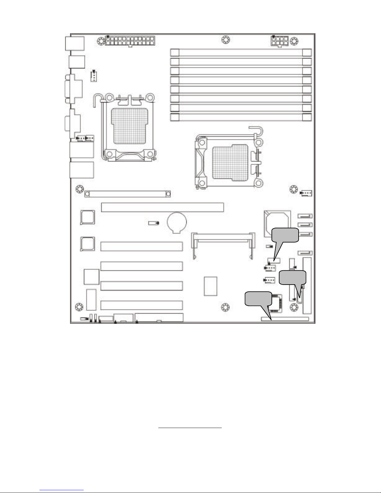
J29
J36 J24
http://www.tyan.com
15
J36: SMDC Connector
J33
CON25X2_M3291
1
3
5
7
9
11
13
15
17
19
21
23
25
27
29
31
33
35
37
41
43
45
47
49
2
4
6
8
10
12
14
16
18
20
22
24
26
28
30
32
34
36
38
40
44
46
48
50
LAD0
LAD2
GND1
GND2
GND3
GND4
I2C1DA
I2C4CLK
GND6
I2C3DA
I2C2CLK
5VSB2
PWRBTN#
RSTBTN#
OEMBTN#
EXTSMI#
CPUNMI#
SIO_RXD
SIO_TXD
SIO_RTS#
SIO_CTS#
SERIRQ
GND12
SMALERTB#
LAD1
LAD3
LFRAME#
PCI_CLK
PCIRST#
I2C1CLK
GND5
I2C4DA
I2C3CLK
5VSB1
I2C2DA
GND7
PCIPME#
COM_TXD
COM_RXD
SOL_CTRL
GND8
COM_RTS#
COM_CTS#
SYSPWRGD
OEMGPIO
BMC_RST#
SMALERTA#
BMC_DET#
For connection with Tyan Server
Management Daughter Card (SMDC).
The SMDC connector is only compatible
with Tyan M3291 (SMDC).
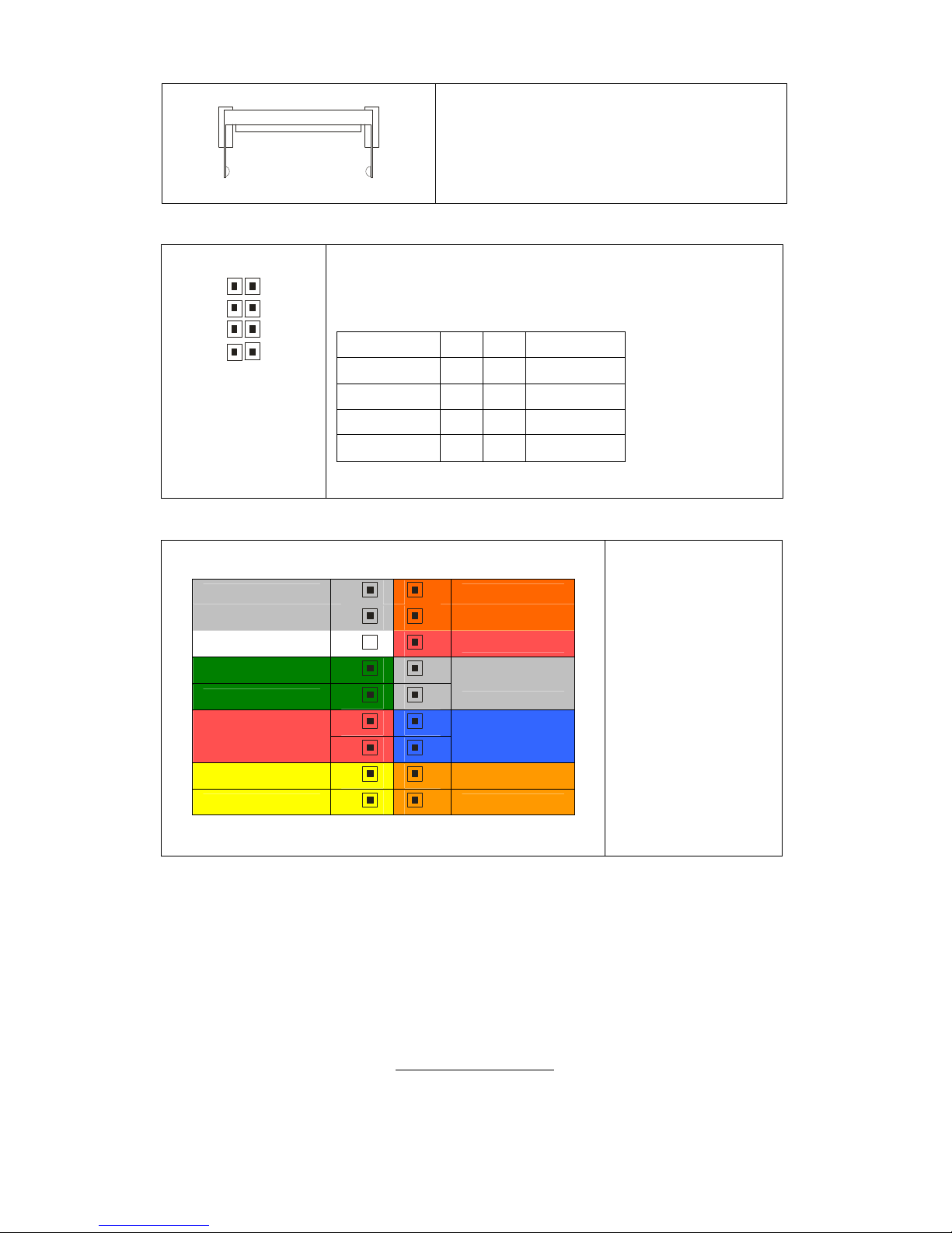
J29: IPMB Pin Header
1
Pin 1 IPMB
DATA
Pin 2 GND
Pin 3 IPMB
CLK
Pin 4 NC
J24: USB Front Panel Header
1 9
2 10
Use this header to connect to front panel USB connector.
Signal Pin Pin Signal
USBPWR 1 2 USBPWR
USB3- 3 4 USB4-
USB3+ 5 6 USB4+
GND 7 8 GND
KEY 9 10
GND
http://www.tyan.com
16
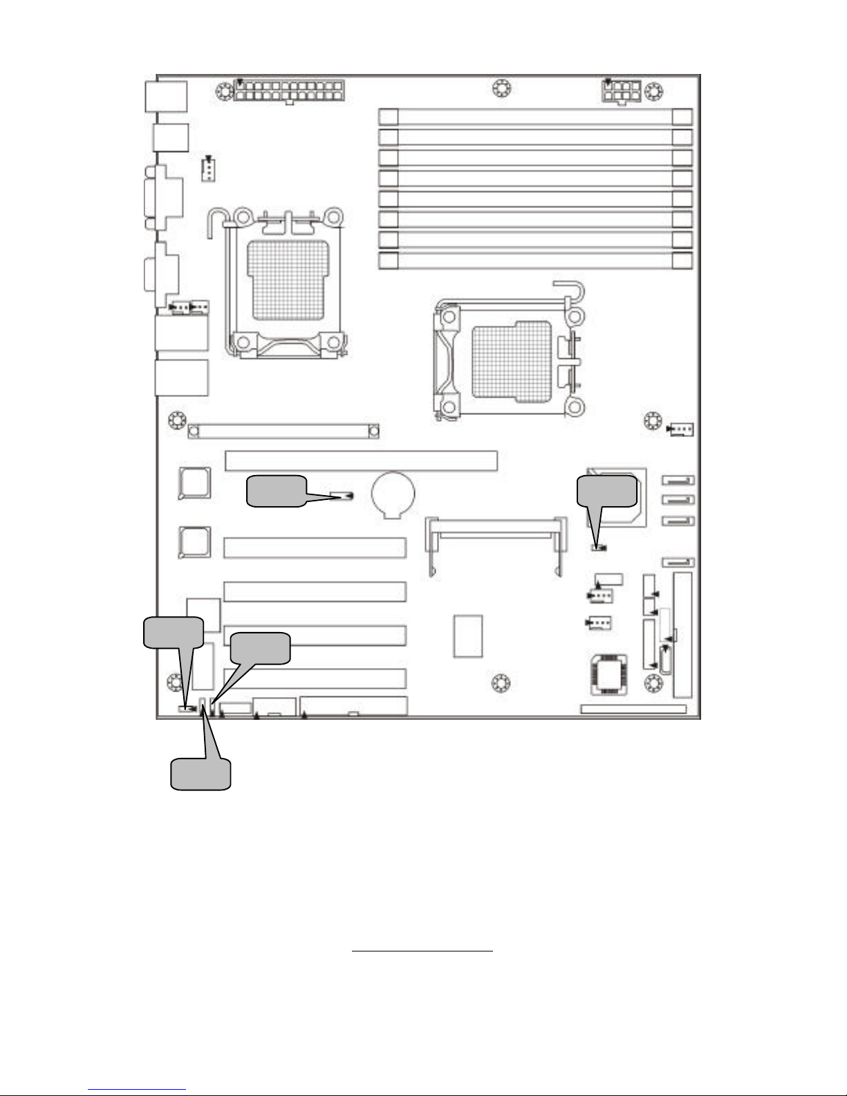
J26 J25
J21
http://www.tyan.com
17
J21: SO-DIMM Socket
Connect SAS/SATA II Daughter Card
(compatible with Tyan M9000-10,
M7901/7902 Ultra 320 SCSI “TARO”
card).
J25: Front Panel SATA LED Pin Header
8
2
7
1
Use these pin definitions to connect front Panel SATA
LED.
Signal Pin Pin Signal
SATA1 LED+ 1 2 SATA1 LEDSATA2 LED+ 3 4 SATA2 LEDSATA3 LED+ 5 6 SATA3 LEDSATA4 LED+ 7 8 SATA4 LED-
J26: Front Panel Header
INTRU
18
17
SMBUS Clock
GND
16
15
SMBUS Data
NC
14
13
+5VSB
FAN FAIL LED-
12
11
FAN FAIL LED+
10
9
NMI
8
7
POWER S/W
6
5
RESET
PWR LED-
4
3
HDD LED-
PWR LED+
2
1
HDD LED+
The motherboard
provides one front
panel header for
electrical
connection to the
front panel
switches and
LED’s.
http://www.tyan.com
18
JP8
JP3 JP2 JP1
JP6
http://www.tyan.com
19
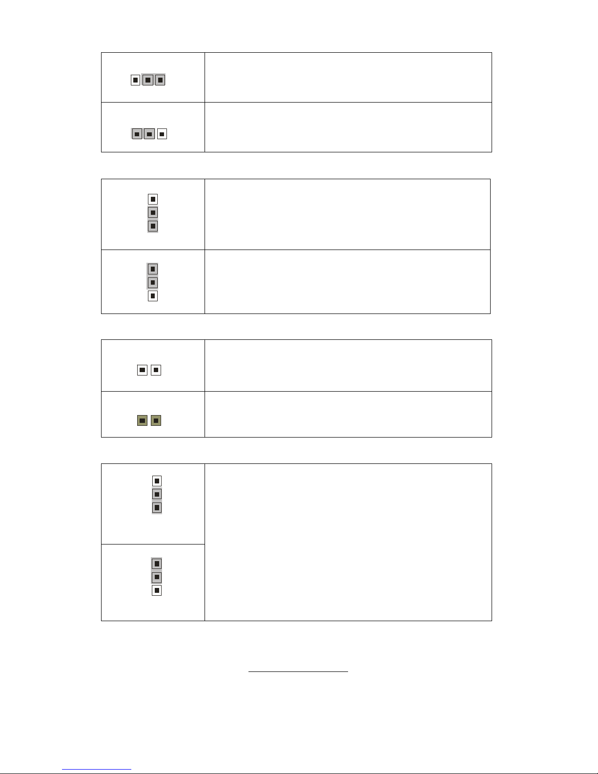
JP1: VGA Enable/Disable Jumper
1
3
(Default) - Enable VGA
3
1
Disable VGA
JP2/JP3: SMDC/ASF2.0 Select Jumper
JP6: PCI-X Frequency Select Jumper
1
100MHz
1
(Default) – 133MHz
JP8: Clear CMOS Jumper
3
1
(Default)
3
1
(Clear)
Use this jumper when you forgot your system/setup
password or need to clear system BIOS setting.
How to clear the CMOS data
- Power off system and disconnect the power
supply from the AC source
- Use jumper cap to close Pin 2 and 3 for several
seconds to Clear CMOS
- Replace jumper cap to close Pin 1 and 2
Reconnect the power supply to the AC source
Power on system
3
1
(Default) - Support ASF2.0
3
1
Support SMDC card
http://www.tyan.com
20
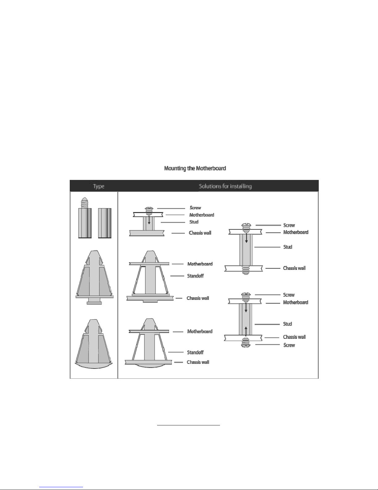
2.4 - Tips on Installing Motherboard in Chassis
Before installing your motherboard, make sure your chassis has the
necessary motherboard support studs installed. These studs are usually
metal and are gold in color. Usually, the chassis manufacturer will pre-install
the support studs. If you are unsure of stud placement, simply lay the
motherboard inside the chassis and align the screw holes of the
motherboard to the studs inside the case. If there are any studs missing,
you will know right away since the motherboard will not be able to be
securely installed.
Some chassis’ include plastic studs instead of metal. Although the plastic
studs are usable, TYAN recommends using metal studs with screws that will
fasten the motherboard more securely in place.
Below is a chart detailing what the most common motherboard studs look
like and how they should be installed.
http://www.tyan.com
21
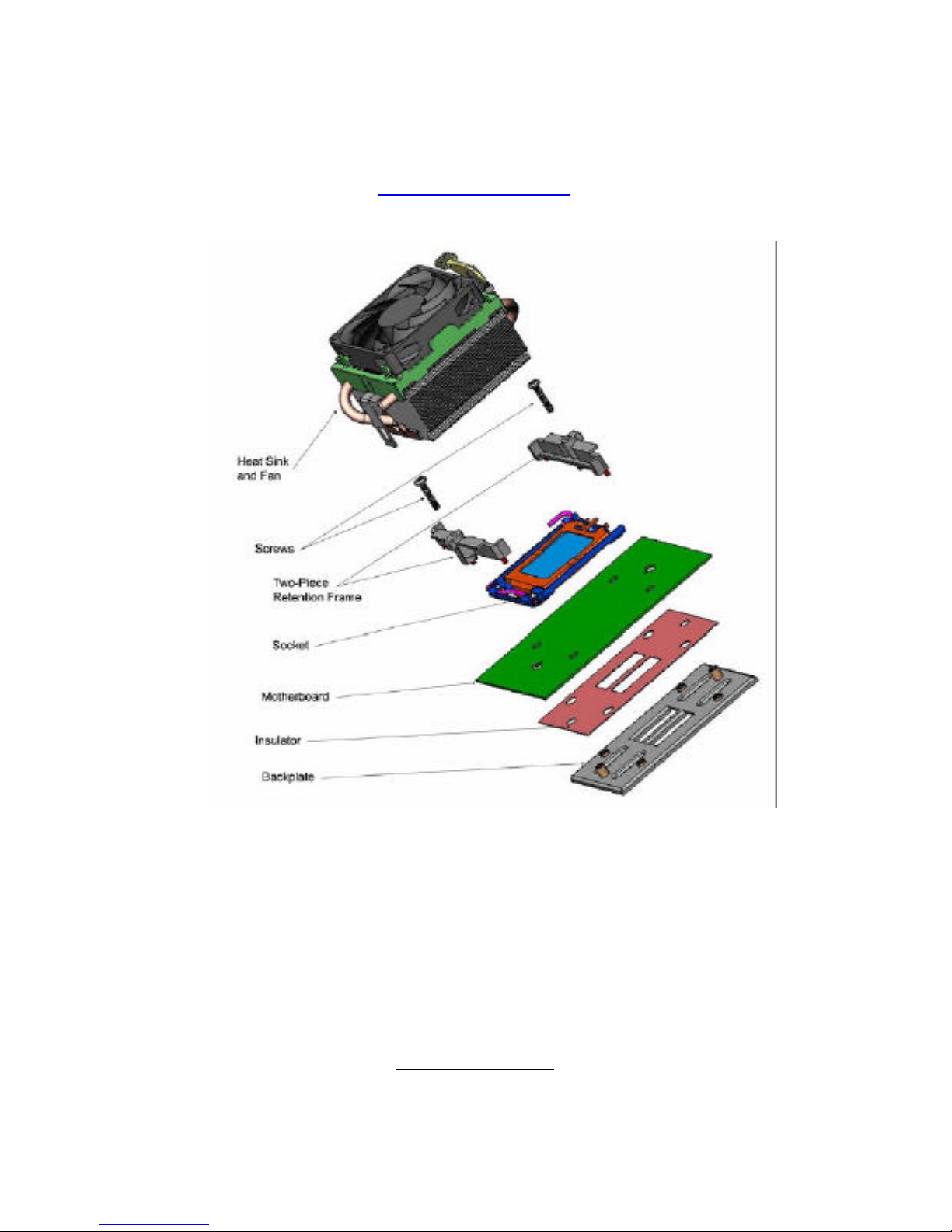
2.5 - Installing the Processor(s)
Your S3970 supports the latest processor technologies from AMD. Check the
TYAN website for latest processor support:
http://www.tyan.com
Figure 1. Exploded View of Thermal Solution AMD PIB Platforms based on AMD
Socket F Processor
http://www.tyan.com
22
Back plate Assembly
The back plate is mounted on the backside of the motherboard and enhances
local stiffness to support shock and vibration loads acting on the heat sink. The
back plate assembly prevents excessive motherboard warpage in the area near
the processor. Without a back plate, excessive warpage could cause serious
damage to electrical connections of the processor socket and integrated circuit
packages surrounding the processor. The back plate also serves as a stiffener
plate for the LGA socket.
While doing the installation, be careful in holding the components.
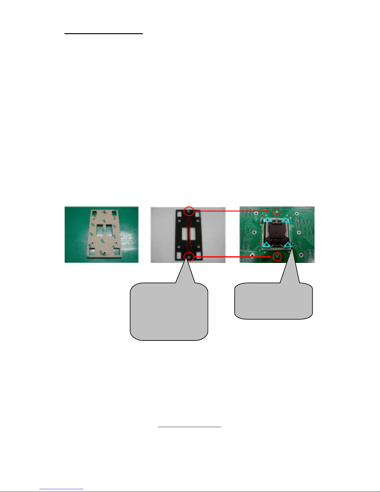
Follow these instructions to install your back plate:
1. Remove the release liner from the back plate.
2. Align the PEM nuts on the back plate to the holes on the reverse side
of the PCB.
3. First, insert the taller upper & lower middle PEM nuts through the
holes of the PCB. The remaining four shorter PEM nuts should
automatically fit the 4 holes on the PCB as shown in the following
pictures.
Let 2 upper &
lower-middle
PEM nuts pass
through the
holes.
4 PEM nuts
should fit 4
holes.
http://www.tyan.com
23
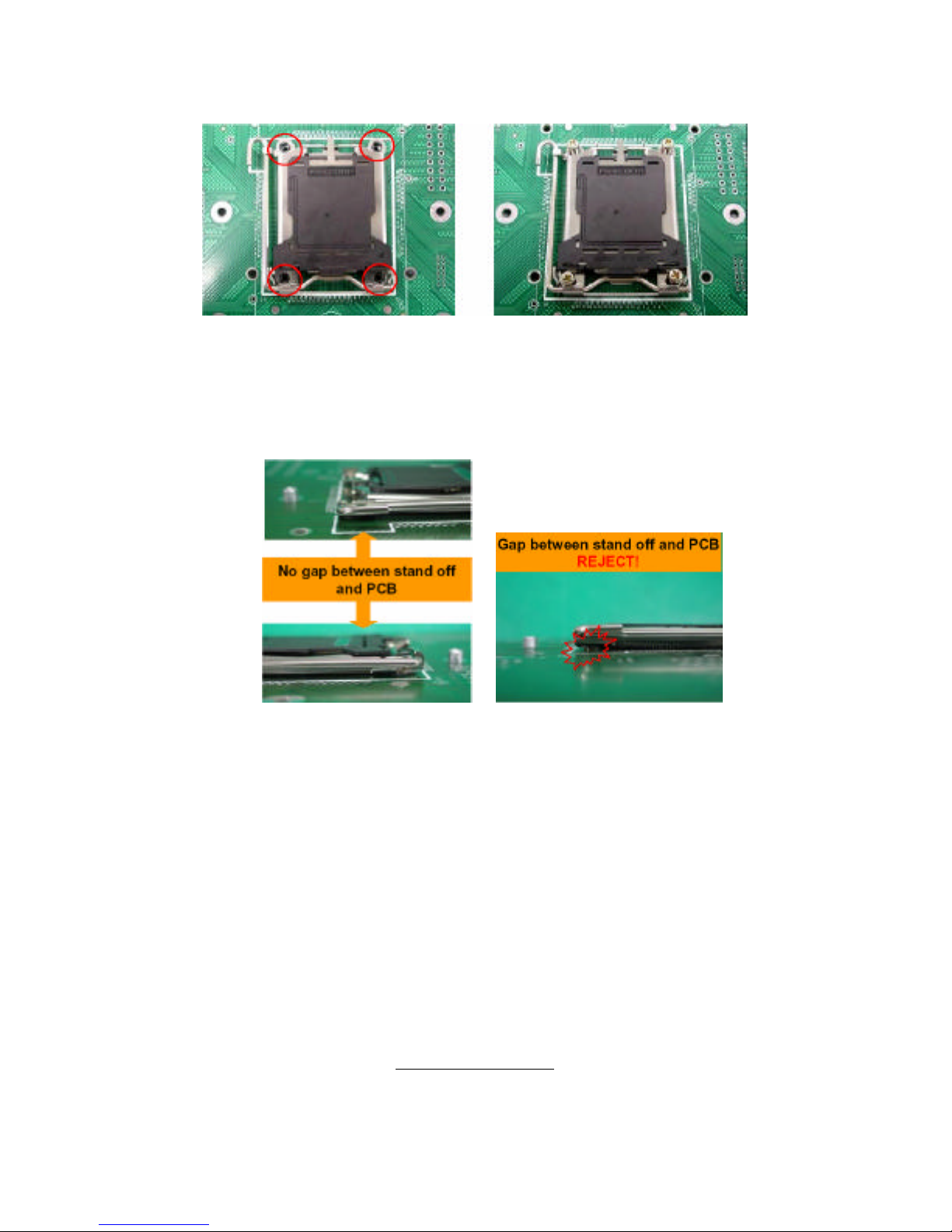
4. Locate four screw holes on socket and screw the socket to the PCB
board.
NOTE: Do not assemble CPU before securing socket with screws.
5. Inspect Socket F assembly to PCB. The Socket F must be tightly
attached onto the PCB. There must NOT be any gap between stand
off the PCB.
http://www.tyan.com
24
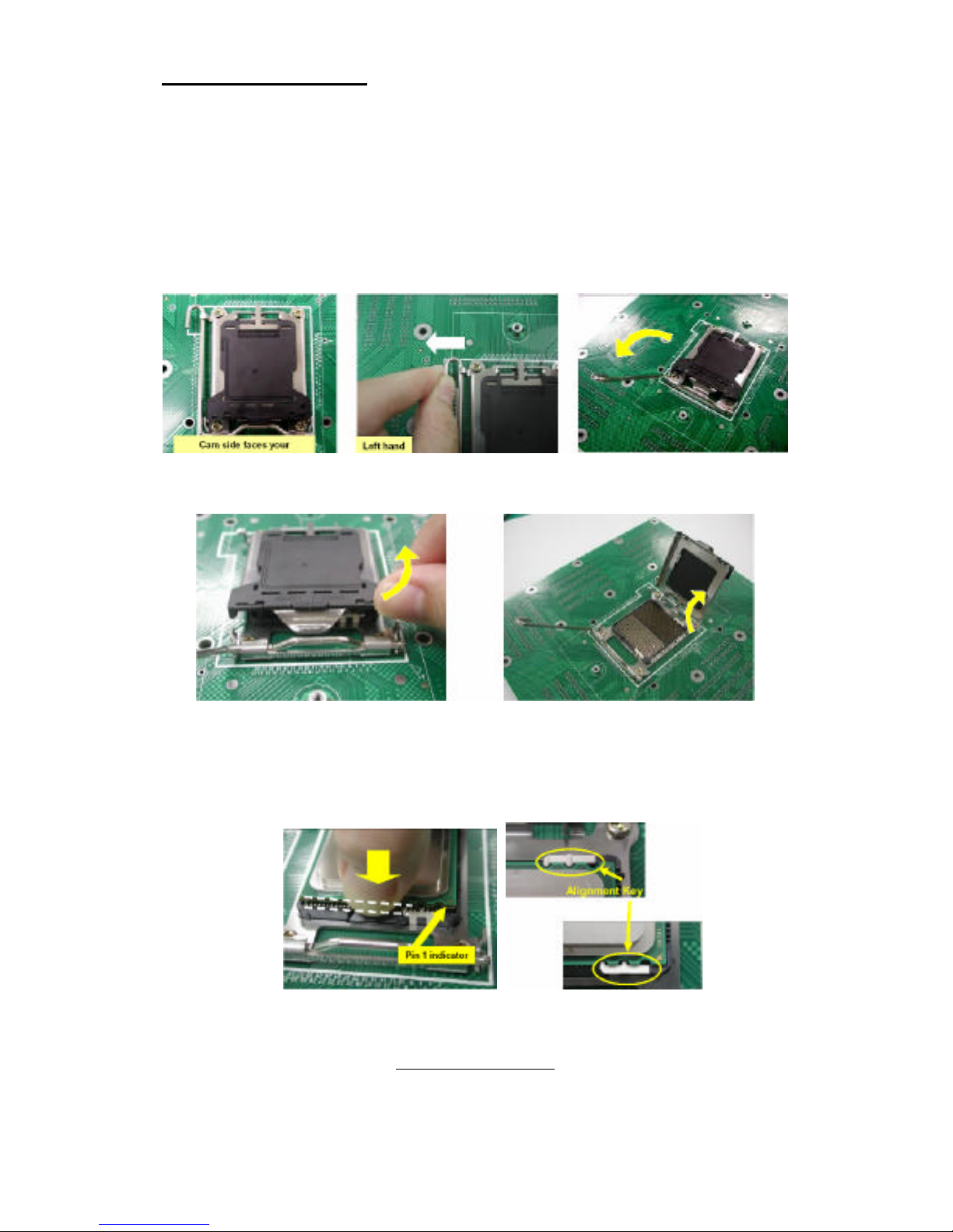
Processor Installation
The processor should be installed carefully. Make sure you are wearing
an antistatic strap and handle the processor as little as possible.
Follow these instructions to install your processor:
1. Place the PCB such that the socket cam side faces you. Make sure
the lever hook is on your top-left side.
2. Use your left thumb and forefinger to hold the lever hook, then pull it
to the left side to clear the retention tab.
3. Rotate the lever to a fully open position.
4. Lift the load plate to a fully open position.
5. Locate the Pin 1 indicator of the package. Align the package with the
socket and carefully insert the package into the socket with vertical
motion only. Vertically check if the CPU is seated well in the socket
housing. If not, take out the CPU, with vertical motion only, and
repeat the above steps.
NOTE: The alignment keys must be located in the notches of the package.
http://www.tyan.com
25
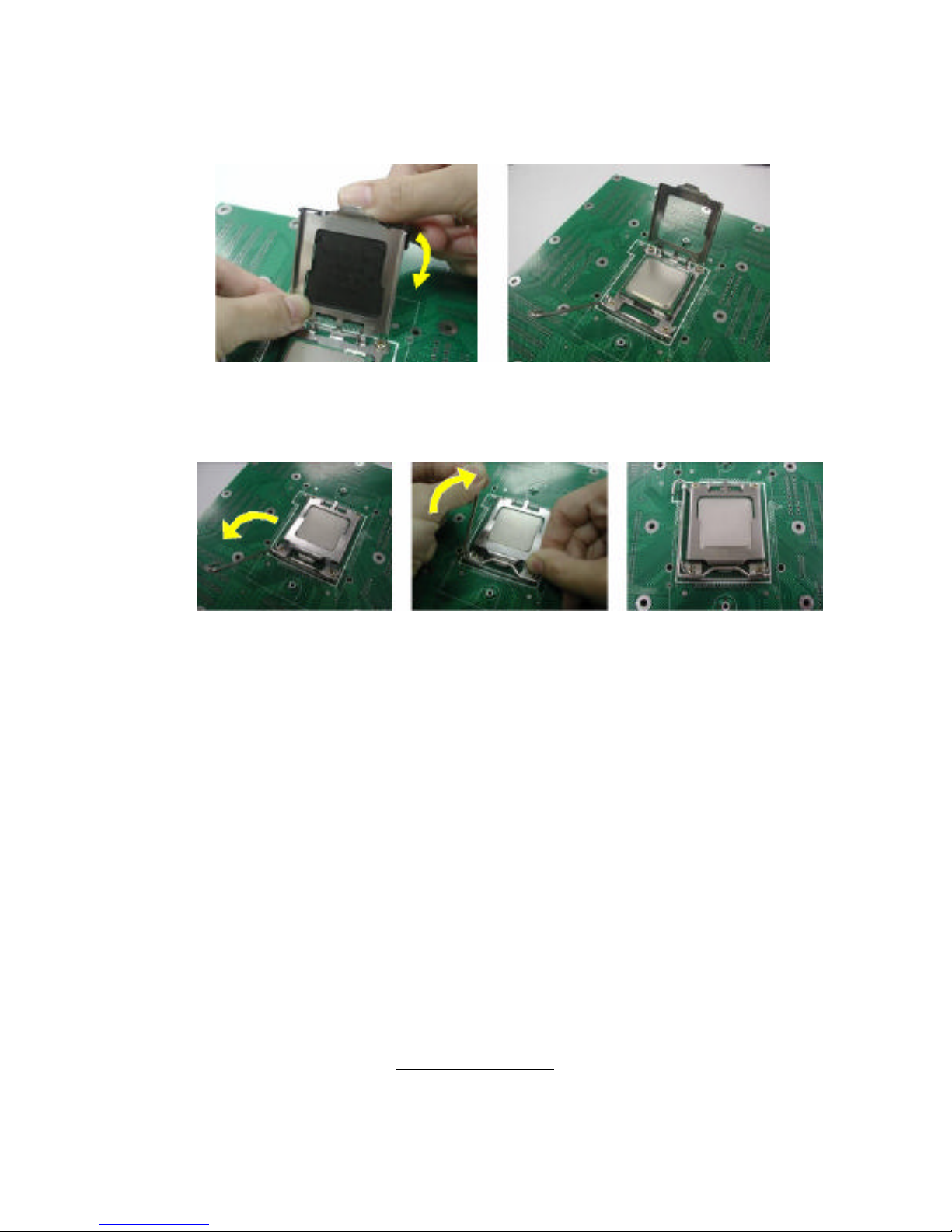
6. Remove the PnP cap. Use your left hand to hold the load plate.
Then use your right thumb to remove the PnP cap from the load plate.
With the package in the socket, the PnP cap removal process will not
damage the contacts.
7. Close the socket. Rotate the load plate onto the package lid.
Engage the load lever while pressing down lightly onto the load plate.
Secure the lever near the hook end under the retention tab.
8. Repeat this procedure for the second processor if necessary.
http://www.tyan.com
26
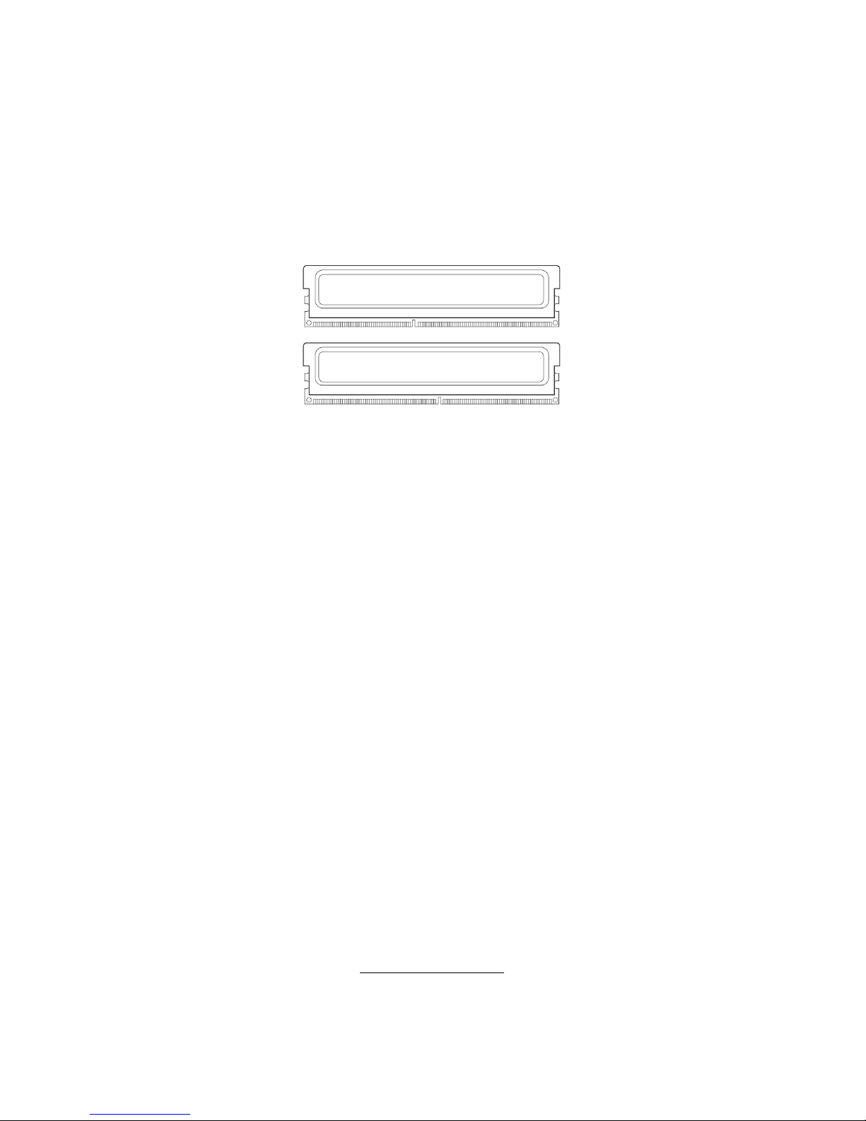
2.6 - Installing the Memory
Before installing memory, ensure that the memory you have is
compatible with the motherboard and processor. Only DDR2667/533/400 DIMM modules are required. Check the TYAN Web site
at: www.tyan.com for details of the type of memory recommended
for your motherboard.
The following diagram shows common types of DDR2 memory modules.
Key points to note before installing memory:
• Only DDR2 667/533 /400 Registered ECC/non-ECC memory
modules are supported.
• All installed memory will automatically be detected and no
jumpers or settings need changing.
http://www.tyan.com
27
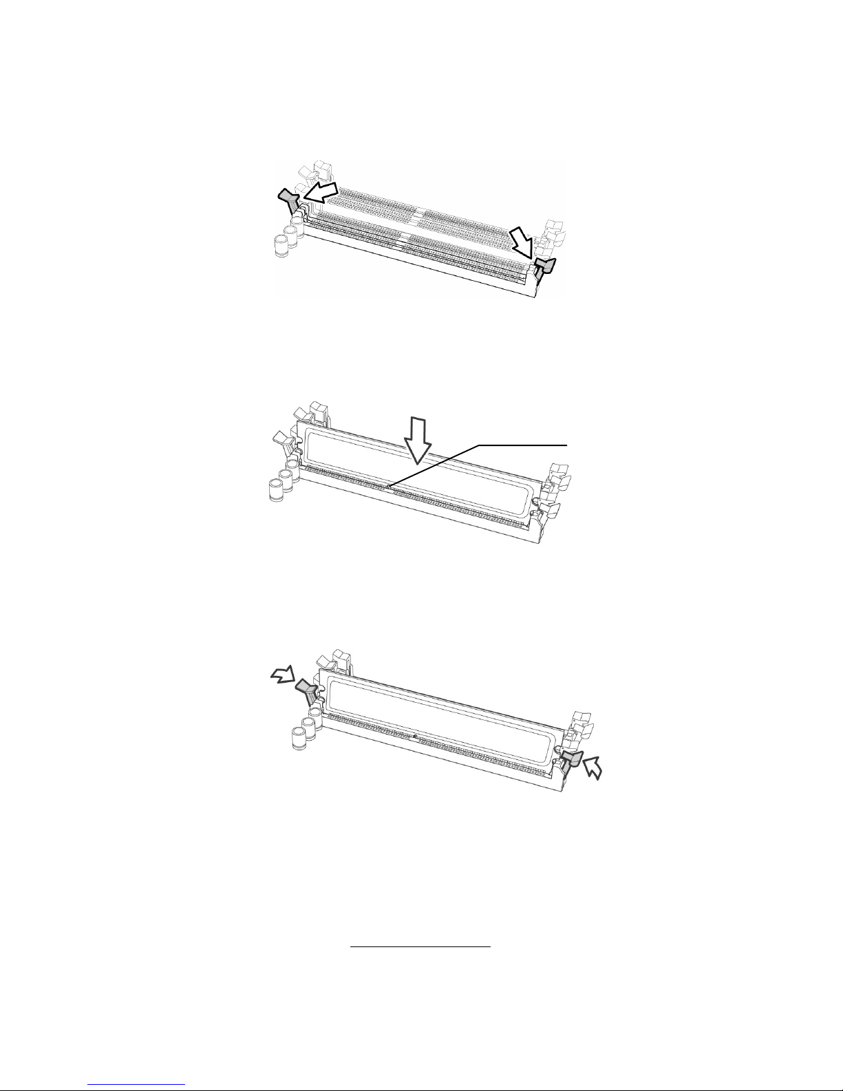
Memory Installation Procedure
Follow these instructions to install memory modules into the S3970.
1. Press the locking levers in the direction shown in the following illustration.
2. Align the memory module with the socket. The memory module is keyed
to fit only one way in the socket.
3. Seat the module firmly into the socket by gently pressing down until it sits
flush with the socket. The locking levers pop up into place.
Key slot
http://www.tyan.com
28
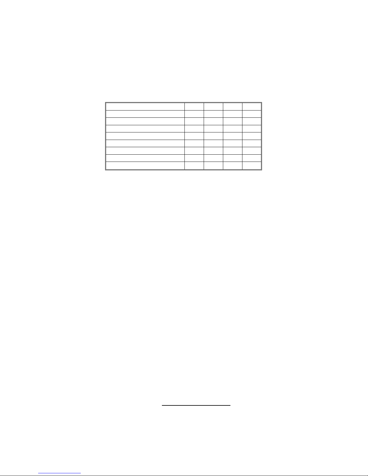
Key points to note before installing memory into Thunder h1000E:
For optimal dual-channel DDR operation, always install memory in pairs
beginning with P1_DIMM7 and P1_DIMM8. Memory modules of the same
type and density are required for dual-channel DDR operation. Mismatched
memory may cause system instability.
Refer to the following table for supported DDRII populations.
(Note: X indicates a populated DIMM slot)
Population Option 1 2 3 4
P1_DIMM1 x
P1_DIMM2 x
P1_DIMM3 x x
P1_DIMM4 x x
P1_DIMM5 x x x
P1_DIMM6 x x x
P1_DIMM7 x x x x
P1_DIMM8 x x x x
http://www.tyan.com
29
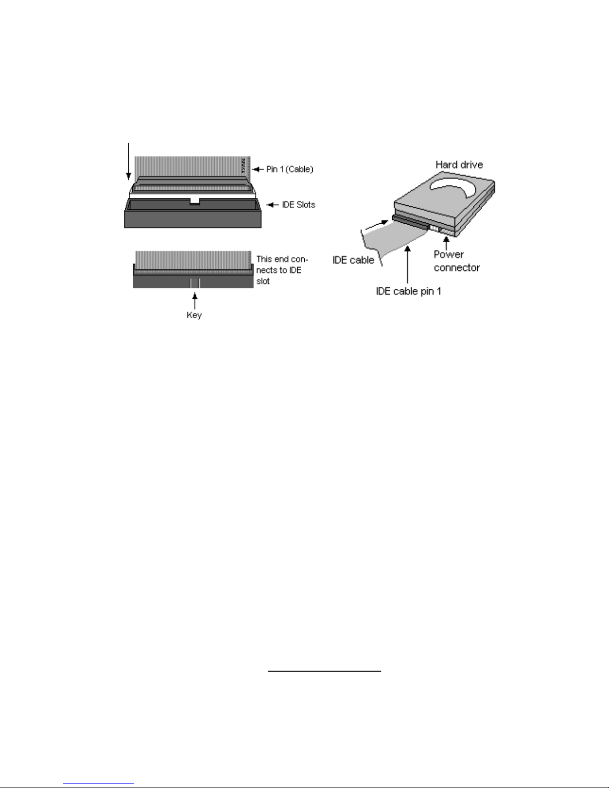
2.7 - Attaching Drive Cables
Attaching IDE Drive Cable
Attaching the IDE drive cable is simple. The cable is “keyed” to only allow it
to be connected in the correct manner.
Attaching IDE cable to the IDE connector is illustrated below:
Simply plug in the BLUE END of the IDE cable into the motherboard IDE
connector, and the other end into the drive. Each standard IDE cable has
three connectors, two of which are closer together. The BLUE connector
that is furthest away from the other two is the end that connects to the
motherboard. The other two connectors are used to connect to drives.
Note: Always remember to properly set the drive jumpers. If only using one
device on a channel, it must be set as Master for the BIOS to detect it.
TIP: Pin 1 on the IDE cable (usually designated by a colored wire)
faces the drive’s power connector.
Attaching Serial ATA Cables
The mainboard is also equipped with 4 Serial ATA (SATA) channels.
Connections for these drives are also very simple.
There is no need to set Master/Slave jumpers on SATA drives.
 Loading...