

TYAN Tomcat H1000S S3950, S3950 User Manual

1
http://www.TYAN.com
Tomcat H1000S
///
S3950
Revision 1.00
Copyright © TYAN Computer Corporation, 2006. All rights reserved. No part of this manual
may be reproduced or translated without prior written consent from TYAN Computer Corp.
All registered and unregistered trademarks and company names contained in this manual
are property of their respective owners including, but not limited to the following.
TYAN, Tomcat H1000S (S3950) are trademarks of TYAN Computer Corporation.
AMD, AMD Opteron, and combinations thereof, are trademarks of Advanced Micro
Devices, Inc.
HyperTransport is a licensed trademark of the HyperTransport Technology Consortium.
AMI, AMIBIOS are trademarks of AMI Software Incorporated.
Microsoft, Windows are trademarks of Microsoft Corporation.
SuSE,is a trademark of SuSE AG.
Linux is a trademark of Linus Torvalds.
QLogic, Zircon, and combinations thereof are trademarks of QLogic Corporation.
IBM, PC, AT, PS/2 are trademarks of IBM Corporation.
Winbond is a trademark of Winbond Electronics Corporation.
Broadcom is a trademark of Broadcom Corporation and/or its subsidiaries
XGI is a trademark of XGI Corporation.
Portable Document Format (PDF) is a trademark of Adobe Corporation.
Information contained in this document is furnished by TYAN Computer Corporation and
has been reviewed for accuracy and reliability prior to printing. TYAN assumes no liability
whatsoever, and disclaims any express or implied warranty, relating to sale and/or use of
TYAN products including liability or warranties relating to fitness for a particular purpose or
merchantability. TYAN retains the right to make changes to product descriptions and/or
specifications at any time, without notice. In no event will TYAN be held liable for any direct
or indirect, incidental or consequential damage, loss of use, loss of data or other malady
resulting from errors or inaccuracies of information contained in this document.

2
http://www.TYAN.com
Table of Contents
Check the box contents! 3
Chapter 1: Introduction
1.00 Congratulations…………………………………………………………………… 4
1.01 Hardware Specifications……………………………………………………….… 4
Chapter 2: Board Installation
2.00 Board Image………………………………………………………………………… 7
2.01 Block Diagram…………………………………………………………………….... 8
2.02 Board Parts, Jumpers and Connectors………………………………………….. 9
2.03 Jumper Settings……………………………………………………………………. 10
2.04 Front Panel SATE LED Pin Header (J11)…………………………………..…… 11
2.05 USB Front Pane (J14)…………...………………………………………………… 12
2.06 COM PORT Pin Header (J20)……………………………………..……………… 12
2.07 FAN Connectors with speed control (J21~25, J33, J34)………………..….….. 13
2.08 2 x 7 Pin Fan Connector (J27)….………………………………………………… 13
2.09 IPMB Pin Header (J28)………………………….………………………………… 14
2.10 SMDC CON25X2_M3291 (J29)………………..…………………………………. 14
2.11 Front Panel Connector (J30)…………………………..………………………….. 15
2.12 TYFP2 For Barebone (J31)…………………………………………..…………… 15
2.13 LCM Pin Header (J32)…………………..…………………………………………. 16
2.14 PCI-X Bus Frequency Configuration Header (J6)…………………….………… 16
2.15 Clear CMOS Jumper by Software (JP1)…………………….….……………….. 17
2.16 PCI/PCI-X Mode Select (JP2)…………………….………………………………. 17
2.17 VGA Enable (JP3)…………..……………………………………………………… 18
2.18 Clear CMOS Jumper by Hardware (JP6)…………..……………………………. 18
2.19 Tips on Installing Motherboard in Chassis………………………………………. 19
2.20 Installing the Memory………………………………………………………………. 21
2.21 Installing the Processor and Heatsink…………………...………....................... 23
2.22 Thermal Interface Material………………………………………………………… 25
2.23 Heatsink Installation Procedures…………………………………………………. 26
2.24 Attaching Drive Cables……………………………………………………………. 28
2.25 Installing Add-in Cards……………………………….......................................... 30
2.26 Installing Optional SO-DIMM Modules…………………………………………… 31
2.27 Connecting External Devices………………………………………………...…… 32
2.28 Installing the Power Supply…………………………………………………...…... 33
2.29 Finishing up…………………………………………………………………………. 33
Chapter 3: BIOS Setup
3.1 BIOS Setup Utility……..…………………………………………………………… 34
3.2 BIOS Menu Bar………….…………………………………………………………. 35
3.3 BIOS Legend Bar……….………………………………………………………….. 35
3.4 BIOS Main Menu……..…………………………………………………………….. 37
3.5 BIOS Advanced Menu...……………………………..……………………………. 38
3.6 BIOS PCI/PnP Menu..……………………………………………………...……… 57
3.7 BIOS Boot Menu……………………………………………………………………. 59
3.8 BIOS Security Menu……………………………………………………………….. 64
3.9 BIOS Chipset Menu………………………………………………………………... 65
3.10 BIOS Exit Menu……………………………………………….……………………. 74
Chapter 4: Diagnostics
4.1 Beep Codes…………………………………………………...……………………. 75
4.2 Flash Utility………………………………………………………………………….. 75
Glossary 76
Technical Support 81
3
http://www.TYAN.com
Before you begin…
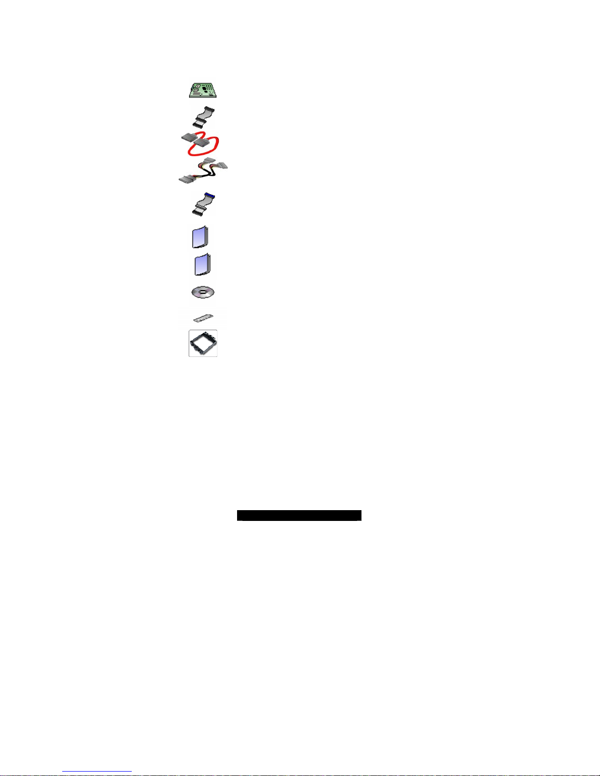
Check the box contents!
The retail motherboard package should contain the following:
1x Tomcat H1000S (S3950) motherboard
1 x 34-Pin floppy drive cable
4 x SATA cable
2 x SATA Drive Power Adapter
1 x Ultra-DMA-66/100 IDE cable
1 x Tomcat H1000S (S3950) User’s Manual
1 x Tomcat H1000S (S3950) Quick Reference Guide
1 x TYAN driver CD
1 x I/O shield
1 x CPU Retention Frame
If any of these items are missing, please contact your vendor/dealer for replacement
before continuing with the installation process.

4
http://www.TYAN.com
Chapter 1: Introduction
1.00 – Congratulations!
You have purchased one of the most powerful AMD Opteron
TM
processor solutions, the
Tomcat H1000S (S3950). The Tomcat H1000S (S3950) is a flexible AMD
®
platform for
multiple applications, based on the HT-1000 chipset. The S3950 is designed to support
the AMD Opteron
TM
processor on an AM2 socket. It features an integrated Dual Gigabit
Ethernet LAN, built-in 16MB XGI XG20
TM
video plus four serial ATA ports. The S3950
offers exceptional performance and versatility for your server platform needs.
Remember to visit TYAN’s Website at http://www.tyan.com
. There you can find
information on all of TYAN’s products with FAQs, distributors list and BIOS setting
explanations.
1.01 – Hardware Specifications
Processor
- Single AM2 socket
- Supports AMD Opteron
TM
1000 Series
Processor
- Up to 800 MHz Hyper-Transport link
support
Chipset
- Broadcom HT1000
- SMSC SCH4307 Super I/O chip
Memory
- Four 240-pin unbuffered DDR2 DIMM
sockets
- Supports up to 8GB of unbuffered
ECC DDR2 400,533,667
- Dual channel memory bus
Expansion Slots
- One 64-bit, 133MHz (3.3V) PCI-X slot
- Four 32-bit, 33MHz PCI v2.3 slots
- Tyan TARO™ SO-DIMM
- Total of five usable slots
Integrated I/O Interfaces
- One floppy connector supports up to two
drives
- One IDE connectors for two IDE devices
- Two USB 2.0 Headers (via cable, 2 x 5pin)
- 2 x 25 connector for Tyan IPMI SMDC
card (M3291)
Integrated 2D Graphics
- XGI XG20 graphics controller
- 16MB Frame Buffer of video memory
(upgradeable to 32MB)
Back Panel I/O Ports
- One PS/2 Keyboard & Mouse ports
- Two RJ45 10/100/1000 Base-T port
w/ activity LED
- Two USB 2.0 ports
- One 9-pin UART Serial port
- One 15-pin VGA port
Integrated LAN Controllers
- Two Intel i82541PI GbE LAN
controllers
- Operating on PCI 32-bit/33MHz bus
- With ASF 2.0/WfM/Teaming support
BIOS
- AMI BIOS® on 8Mbit LPC Flash ROM
- Serial Console Redirect
- USB boot supported
- Supports ACPI
- PnP, DMI 2.0, WfM 2.0 Power
Management

5
http://www.TYAN.com
- Four SATA ports
- One COM2 header
System Management
- One Analog Device ADT7476
- Temperature and voltage monitoring
- One (1) 3+1-pin CPU fan header with
tachometer monitoring and smart FAN
control
- Six (6) 3+1-pin system fan headers with
tachometer monitoring, all of them support
smart FAN control
- One 2 x 7-pin fan con (reserve to support
TYAN FAN Adapter Board---M1012)
- Watchdog timer support
Integrated SATA Controller
- Supports four SATA ports running at
1.5Gb/s with NCQ
- RAID 0, 1, 5 and 10 supported
Power
- Onboard 4-phase VRD
- EPS12V (24+8) power connectors
Form Factor
- ATX footprint
- 12" x 9.6"; 305mm x 244mm
- 6-layer board
Regulatory
- FCC Class B (Declaration of
Conformity)
- European Community CE
(Declaration of Conformity)
Software Specifications
OS (Operating System) Support
Microsoft Windows Server 2003 + SP1 32-bit
Microsoft Windows Server 2003 64-bit
SuSE 9.3 Pro 32/64-bit
SuSE 9.0 + SP2 32/64-bit
SuSE 10 64-bit
RHEL3 Update 5 32-bit
RHEL4 Update 1 32/64-bit
TYAN reserves the right to add support or discontinue support for any OS with or
without notice.
6
http://www.TYAN.com
Chapter 2: Board Installation
Installation
You are now ready to install your motherboard. The mounting-hole pattern of the Tomcat
H1000S (S3950) matches the ATX specification. Before continuing with installation,
confirm that your chassis supports an ATX motherboard.
How to install our products right…. the first time!
The first thing you should do is read this user’s manual. It contains important information
that will make configuration and setup much easier. Here are some precautions you should
take when installing your motherboard:
(1) Ground yourself properly before removing your motherboard from the antistatic
bag. Unplug the power from your computer power supply and then touch a
safely grounded object to release static charge (i.e. power supply case). For the
safest conditions, Tyan recommends wearing a static safety wrist strap.
(2) Hold the motherboard by its edges and do not to uch the bottom of the board, o r
flex the board in any way.
(3) Avoid touching the motherboard components, IC chips, connectors, memory
modules, and leads.
(4) Place the motherboard on a grounded antistatic surface or on the antistatic bag
that the board was shipped in.
(5) Inspect the board for damage.
The following pages include details on how to install your motherboard into your chassis,
as well as installing the processor, memory, disk drives and cables.
NOTE DO NOT APPLY POWER TO THE BOARD IF IT HAS BEEN DAMAGED
7
http://www.TYAN.com
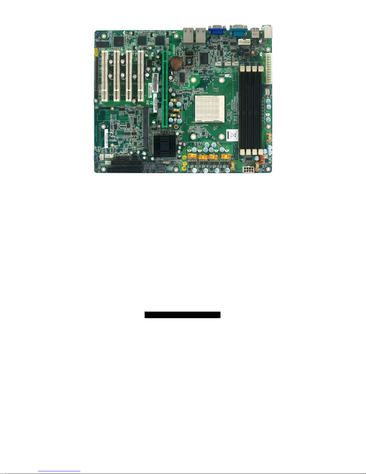
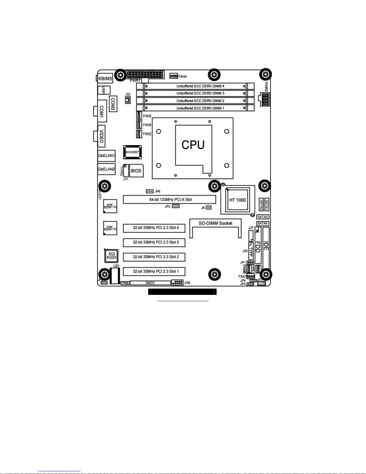
2.00 – Board Image
This picture is representative of the latest board re vision a vailable at the ti me of
publishing. The board you receive may or may not look exac tly like the above
picture.
The following page includes details on the vital components of this motherboard.

8
http://www.TYAN.com
2.01--Block Diagram
9
http://www.TYAN.com
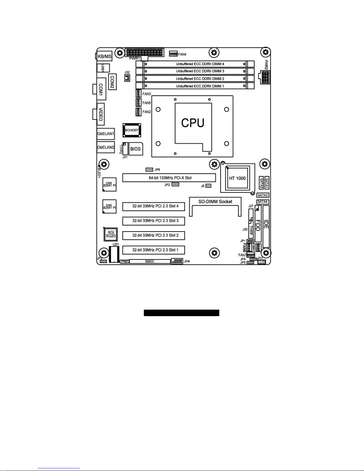
2.02 – Board Parts, Jumpers and Connectors
This diagram is representative of the latest board revision available at the t ime of
publishing. The board you receive may not look exactly like the above diagram.
http://www.tyan.com
10
2.03 – Jumper Settings
Jumper Function Settings
J11
Front Panel SATA LED
Pin Header
See Section 2.04
J14 USB Front Panel See Section 2.05
J20 COM PORT Pin Header See Section 2.06
J21~J25,
J33, J34
FAN Connectors with speed control See Section 2.07
J27 2 x 7 Pin Fan Connector See Section 2.08
J28 IPMB Pin Header See Section 2.09
J29 SMDC Connector See Section 2.10
J30 Front Panel Connector See Section 2.11
J31 TYFP2 For Barebone See Section 2.12
J32 LCM Pin Header See Section 2.13
J6
PCI-X Bus Frequency Configuration
Header
See Section 2.14
JP1 Clear CMOS Jumper by Software See Section 2.15
JP2 PCI/PCIX Mode Select See Section 2.16
JP3 VGA Enable See Section 2.17
JP6 Clear CMOS Jumper by Hardware See Section 2.18
http://www.tyan.com
11
Jumper Legend
OPEN - Jumper OFF Without jumper covered
CLOSED - Jumper ON With jumper covered
To indicate the location of pin-1
To indicate the location of pin-1
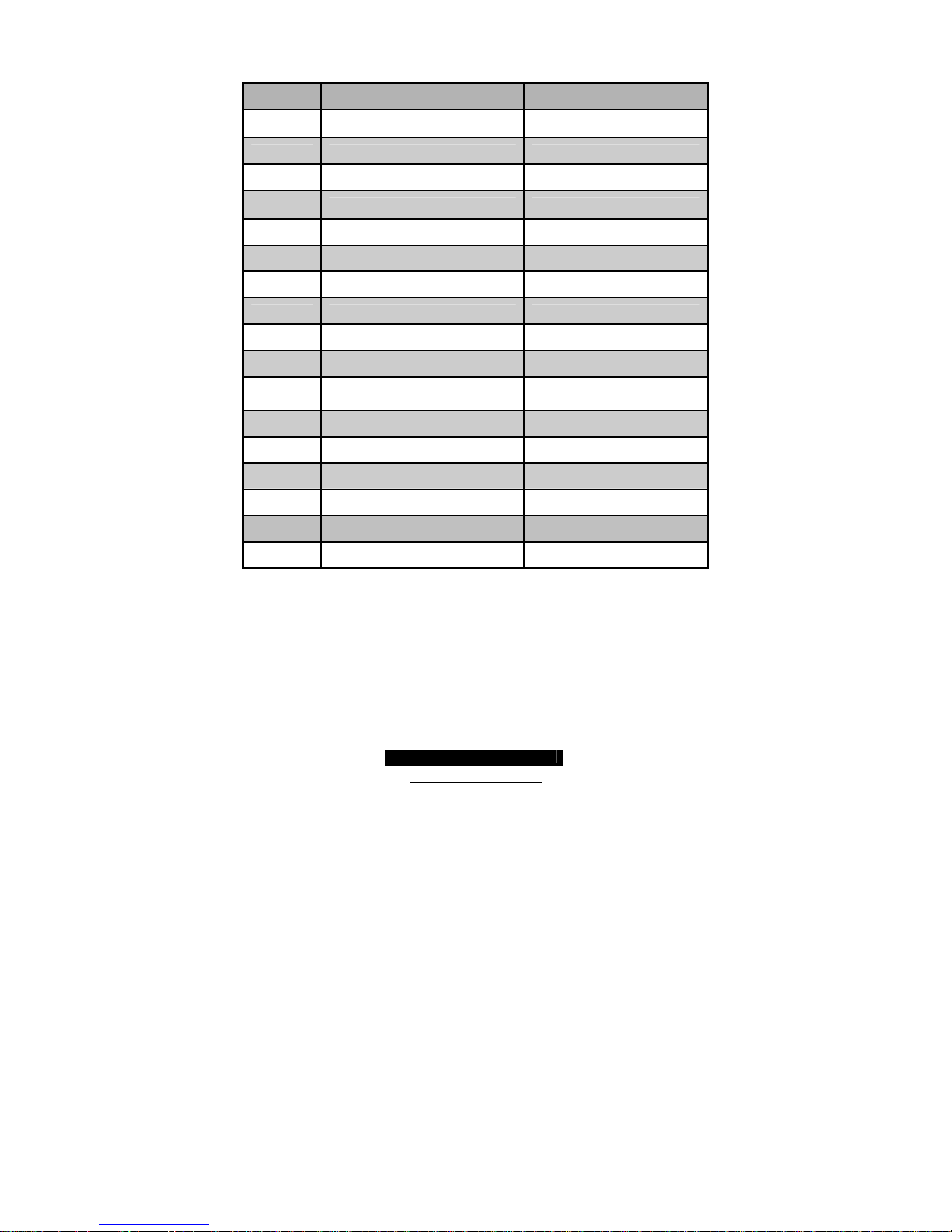
2.04 – Front Panel SATA LED Pin Header (J11)
Signal
Description
Pin # Pin # Signal
Description
SATA1 LED+
1 2
SATA1 LED--
SATA2 LED+
3 4
SATA2 LED--
SATA3 LED+
5 6
SATA3 LED--
SATA4 LED+
7 8
SATA4 LED--
http://www.tyan.com
12
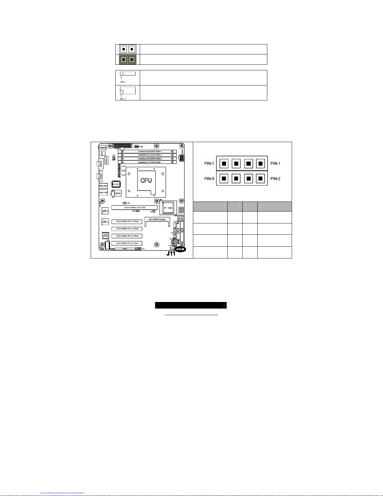
2.05 – USB2.0 Header (J14)
Signal
Description
Pin # Pin # Signal
Description
USB PWR
1 2
USB PWR
USB 3 - -
3 4
USB 4 - -
USB 3 +
5 6
USB 4 +
GND
7 8
GND
KEY
9 10
GND
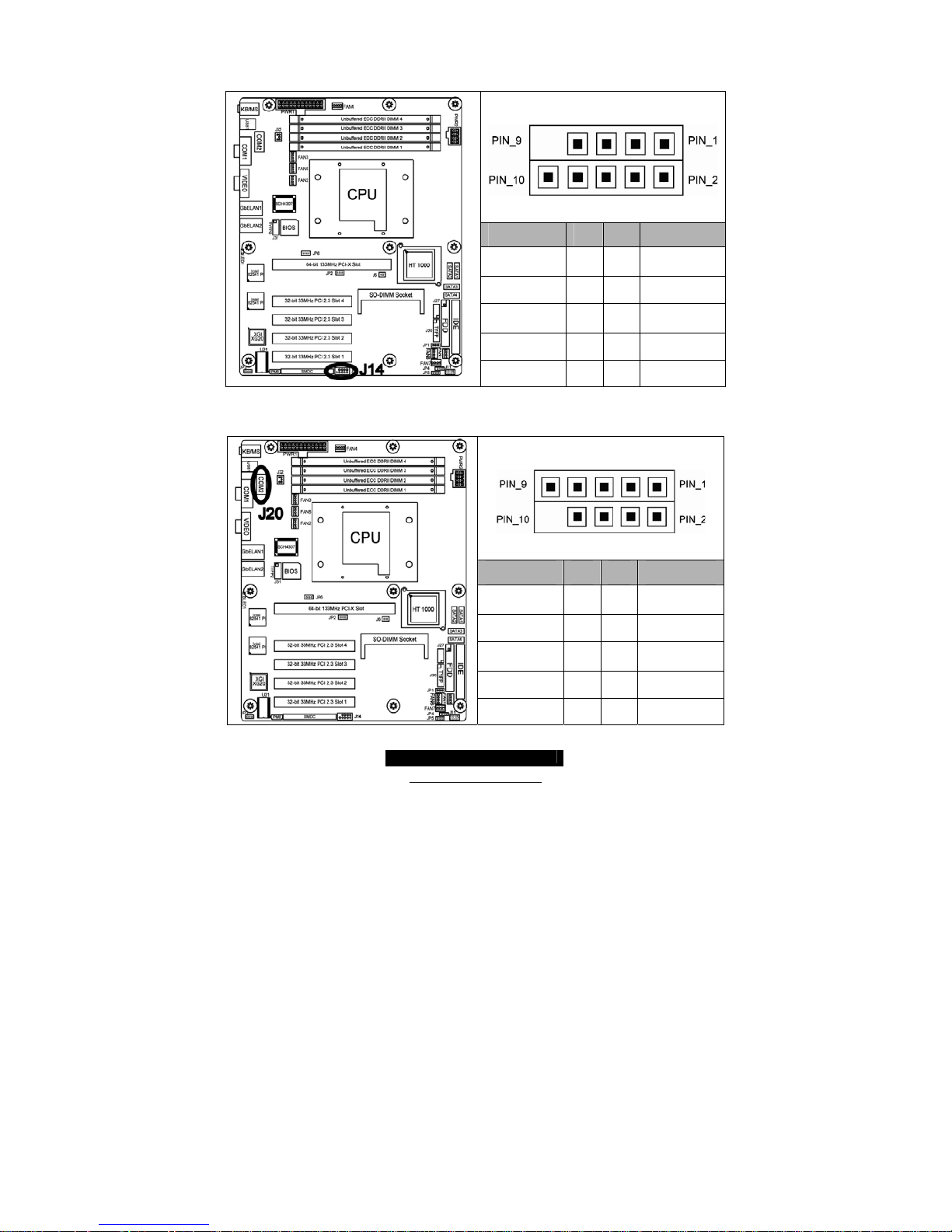
2.06 – COM2 PORT Pin Header (J20)
Signal
Description
Pin # Pin # Signal
Description
DCD
1 2
DSR
RXD
3 4
RTS
TXD
5 6
CTS
DTR
7 8
RI
GND
9 10
KEY

http://www.tyan.com
13
2. 07 – FAN Connectors with Speed Control (J21~J25, J33, J34)
Pin_4: Speed control
Pin_3 : Tachometer
Pin_2 : +12V
Pin_1
Pin_1 : GND
2.08 – 2 x 7 Pin Fan Connector (J27)
NOTE: This 2 x 7 Pin Fan Connector is
for Tyan Barebone use only.
Signal Pin Pin Signal
BB_FAN1_TACH
1 2
NC
BB_FAN2_TACH
3 4
NC
BB_FAN3_TACH
5 6
NC
BB_FAN4_TACH
7 8
NC
BB_FAN5_TACH
9 10
NC
GND
11 12
Key
GND
13 14
FAN1_PWM
http://www.tyan.com
14
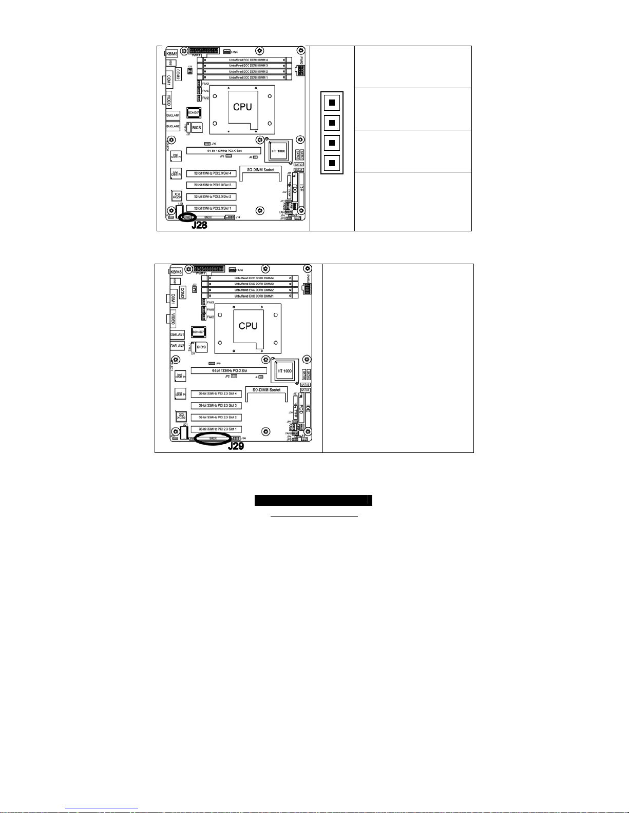
2.09 – IPMB Pin Header (J28)
Pin_4 : NC
Pin_3 : IPMB CLK
Pin_2 : GND
Pin_1
Pin_1 : IPMB DATA
2.10 – SMDC Connector (J29)
For connection with Tyan Server
Management Daughter Card (SMDC).
The SMDC connector is compatible only
with the Tyan M3291 (SMDC).
http://www.tyan.com
15
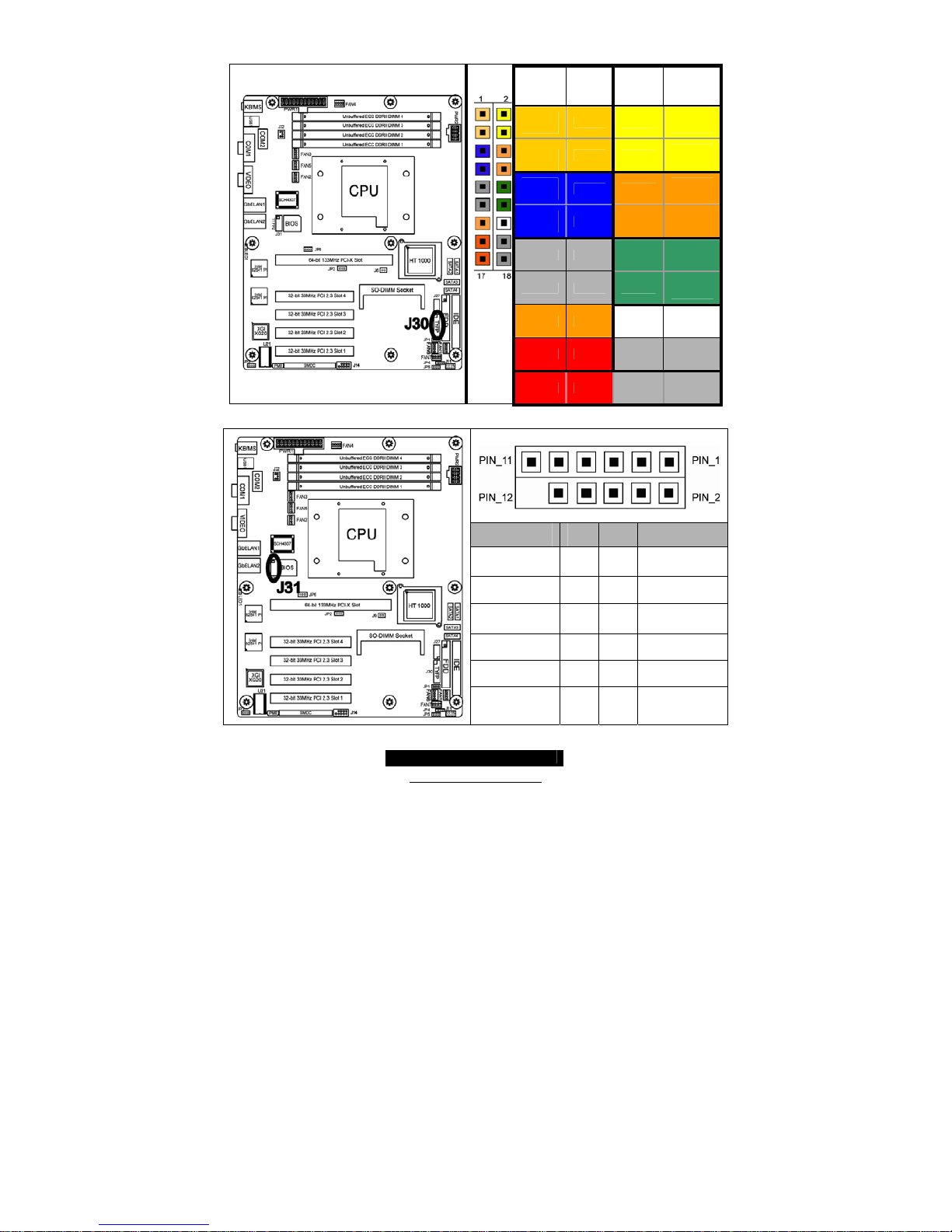
2.11 – Front Panel Connector (J30)
Signal PIN # PIN # Signal
HDD
LED+
1 2
PWR
LED+
HDD
LED-
3 4
PWR
LED-
Reset
Button -
5 6
POWER
S/W
Reset
Button+
7 8
POWER
S/W
NMI
9 10
FANFAIL
LED
NMI
11 12
FANFAIL
LED
5VSB
13 14
NC
SDA
15 16
GND
SCL
17 18
Intruder
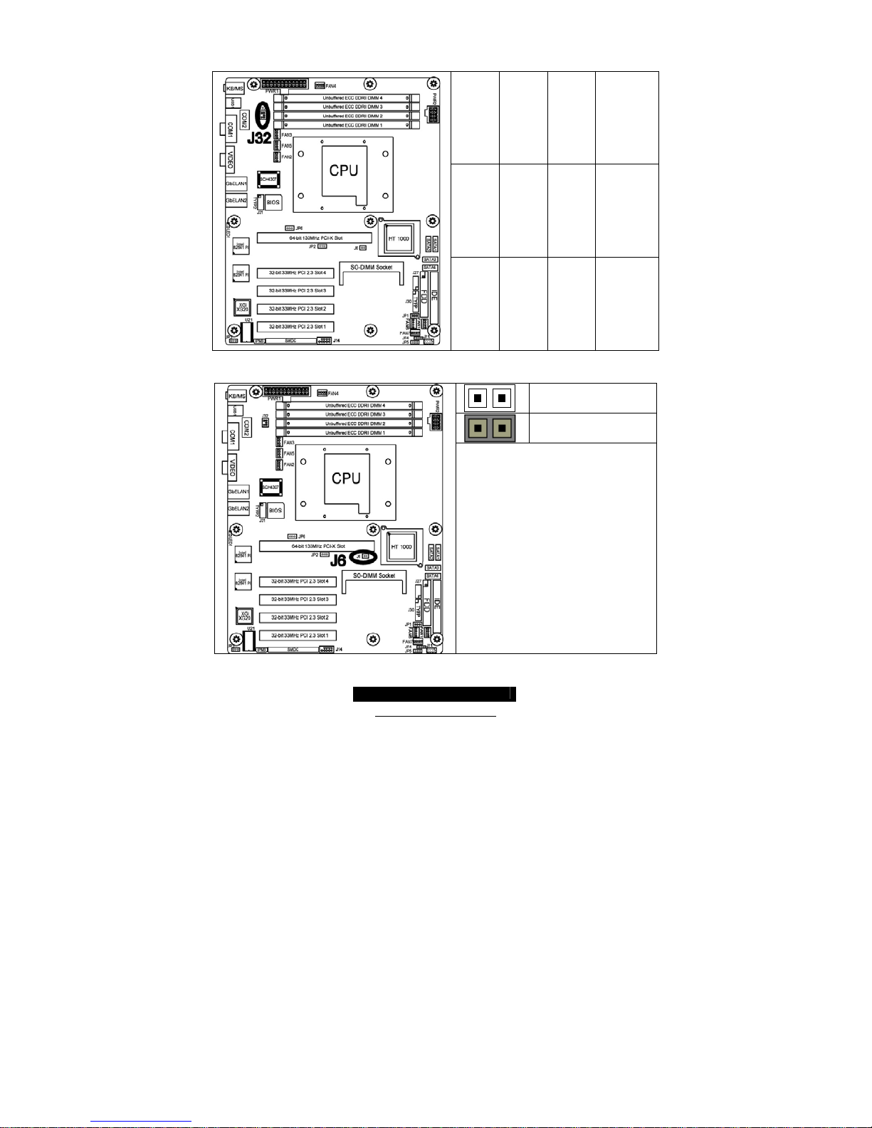
2.12 – TYFP2 For TYAN Barebone (J31)
Signal
Description
Pin # Pin # Signal
Description
LAN1 LED+
1 2
LAN1 LED--
LAN2 LED+
3 4
LAN2 LED--
NC
5 6
NC
ID LED+
7 8
ID LED--
ID BUTTON+
9 10
ID BUTTON--
NC
11 12
KEY
http://www.tyan.com
16
2.13 – LCM Pin Header (J32)
VCC PIN 1 PIN 2 RXD2
KEY PIN 3 PIN 4 GND
5VSB PIN 5 PIN 6 TXD2
2.14 – PCI-X Bus Frequency Configuration Header (J6)
OPEN - Jumper OFF
CLOSED - Jumper ON
J6 is used to adjust PCI-X frequency
Open(Default): 66MHz/100MHz;
Closed: 133MHz
http://www.tyan.com
17
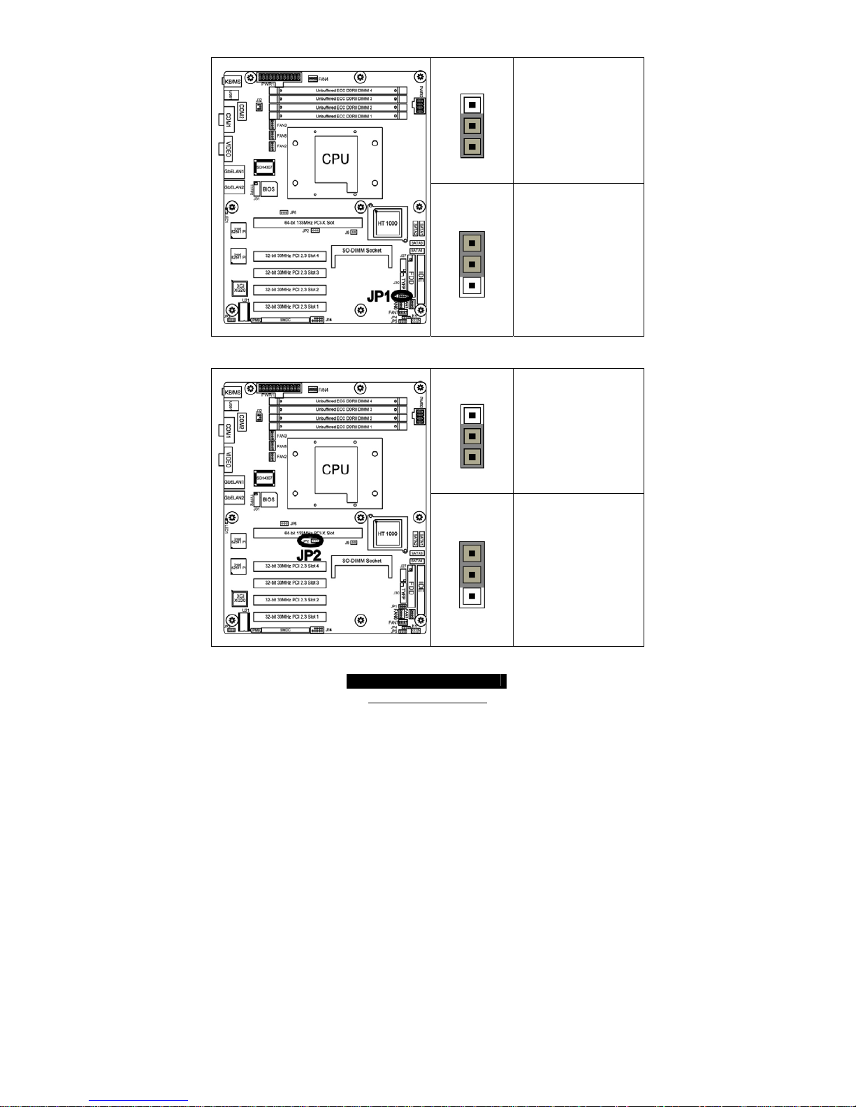
2.15 – Clear CMOS Jumper by Software (JP1)
Pin_3
Pin_1
DEFAULT
Pin_3
Pin_1
Clear CMOS
By Software
NOTE: BIOS will clear CMOS
during the POST process
automatically when selected.
2.16 - PCI/PCI-X Mode Select (JP2)
Pin_3
Pin_1
Auto Detect PCI-X
Device
Pin_3
Pin_1
Force to PCI Mode
http://www.tyan.com
18
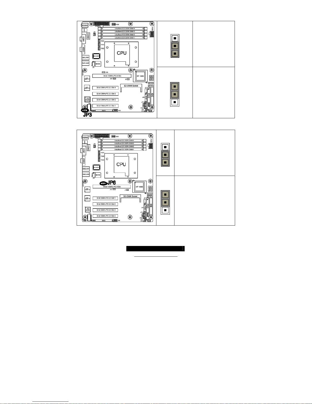
2.17 – VGA Enable (JP3)
Pin_3
Pin_1
DEFAULT
VGA Enable
Pin_3
Pin_1
Disable
XG20 VGA
2.18 – Clear CMOS Jumper by Hardware (JP6)
Pin_3
Pin_1
DEFAULT
Pin_3
Pin_1
You can reset the CMOS settings by using
this jumper or if you have forgotten your
system/setup password.
- Power off system and
disconnect both power
connectors from the
motherboard
- Use jumper cap to close
Pin_2 and Pin_3 for
several seconds to Clear
CMOS
- Put jumper cap back to
Pin_1 and Pin_2 (default
setting)
Reconnect power and power on the system
http://www.tyan.com
19
2.19 – Tips on Installing the Motherboard in Chassis
Before installing your motherboard, make sure your chassis has the necessary
motherboard support studs installed. These studs are usually metal and are gold in color.
Usually, the chassis manufacturer will pre-install the support studs. If you’re unsure of stud
placement, simply lay the motherboard inside the chassis and align the screw holes of the
motherboard to the studs inside the case. If there are any studs missing, you will know
right away since the motherboard will not be able to be securely installed.
Thunder H1000S (S3950) Mounting Hole Placement

http://www.tyan.com
20
Some chassis include plastic studs instead of metal. Although the plastic studs are usable,
Tyan recommends using metal studs with screws that will fasten the motherboard more
securely
in place.
Below is a chart detailing what the most common motherboard studs look like and how
they should be installed.
TIP: Use metal studs if possible, as they hold the motherboard into place more securely
than plastic standoffs.
http://www.tyan.com
21
2.20 – Installing the Memory
Before attempting to install any memory, make sure that the memory you have is
compatible with the motherboard as well as the processor*. A Critical aspect to system
building is whether you’re using the recommended memory for the motherboard that you
have. For compatibility information, please check Tyan’s web site at: www.tyan.com
* Not all stepping’s of AMD Opteron CPU’s support the same type of memory speeds.
Consult with AMD for clarification.
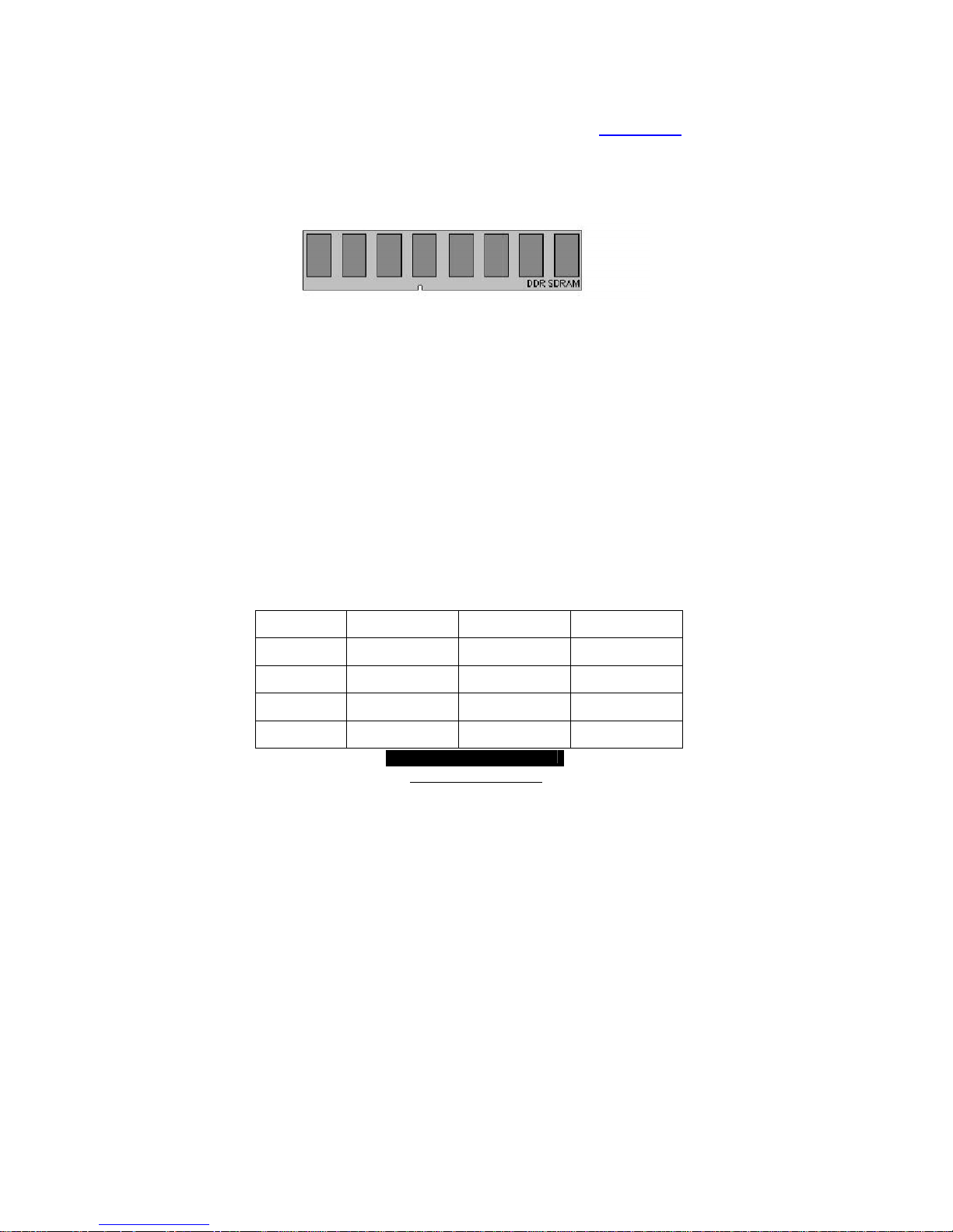
The following diagram shows the common types of RAM modules you may encounter
depending on your board:
Here are a few key points to note before installing memory into your Tomcat h1000S:
• AMD Opteron
TM
processors support 64bit (non-interleaved) or 128bit (interleaved)
memory configurations
• At least ONE Unbuffered DDR2 SDRAM module must be installed for the system
to turn on and POST (power on self test)
• 128MB, 256MB, 512MB, 1GB and 2GB* Unbuffered ECC DDR2 400,533,667
SDRAM memory modules are supported
• All installed memory will be automatically detected
• The Tomcat H1000S supports up to 8GB*.
*Not validated at the time of print, subject to change.
Valid DIMM Configurations
The processor supports 64-bit mode and 128-bit mode configurations of the DIMMs. In
64-bit mode, only DIMMs 1 and 3 can be populated. Possible combinations of DIMMs in
64-bit mode are listed in the table as below. In 128-bit mode, a minimum of two DIMMs are
required to create the 128-bit bus; therefore, DIMMs can only be populated in even
numbered pairs in slots 1 & 2, and 3 & 4. The following table shows some possible
combinations of DIMMs for 128-bit mode. Not all possible combinations are listed in
the table.
DIMM
Number
64-Bit Width 128-Bit Width Bank
Interleave
DIMM0 Bank 0 Bank 0, low 64 Bank 0, low 64,
even
DIMM1 Not Used Bank 0, high 64 Bank 0, high 64,
even
DIMM2 Bank 1 Bank 1, low 64 Bank 0, low 64,
odd
DIMM3 Not Used Bank 1, high 64 Bank 0, high 64,
odd
http://www.tyan.com
22
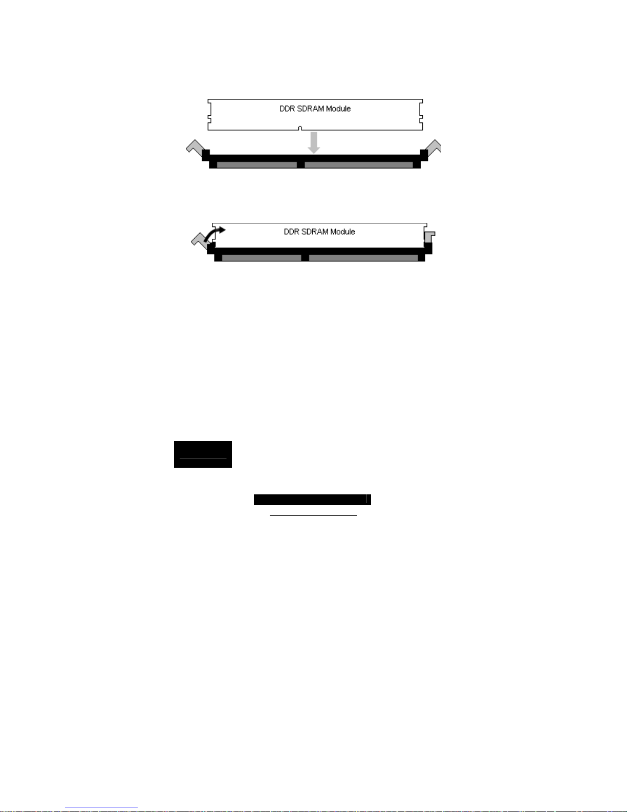
Memory Installation Procedure
When installing memory modules, make sure the modules align properly with the memory
socket. There should be keys (small indents) on your memory modules that fit according to
the keys in the memory socket. DDR2 modules and sockets have only one key, which is
slightly near the center of the module/socket. The method of installing memory modules is
detailed in the following diagrams.
DDR SDRAM DIMM Slot – 240 Pins (1 Key)
Once the memory modules are firmly seated in the socket, two clamps on either side will
close and secure the module into the socket. Sometimes you may need to close the
clamps manually.
DDR SDRAM DIMM Slot – 240 Pins (1 Key)
To remove the memory module, simply push the clamps outwards until the memory
module pops up. Then simply remove the module.
TIP: When installing memory, a module may require a considerable amount of force to
seat properly, although this is very rare. To avoid bending and damaging your
motherboard, place it on its anti-static bag and onto a flat surface, and then proceed with
memory installation.
NOTE
YOU MUST ALWAYS unplug the power connector to the
motherboard before performing system hardware changes, to
avoid damaging the board or expansion device.
http://www.tyan.com
23
2.21 – Installing the Processor and Heatsink
Your Tomcat H1000S (S3950) supports the latest 64-bit processor technologies from AMD.
However, only AMD Opteron
TM
processor are certified and supported with this
motherboard. Reference the Tyan website for further details: www.tyan.com
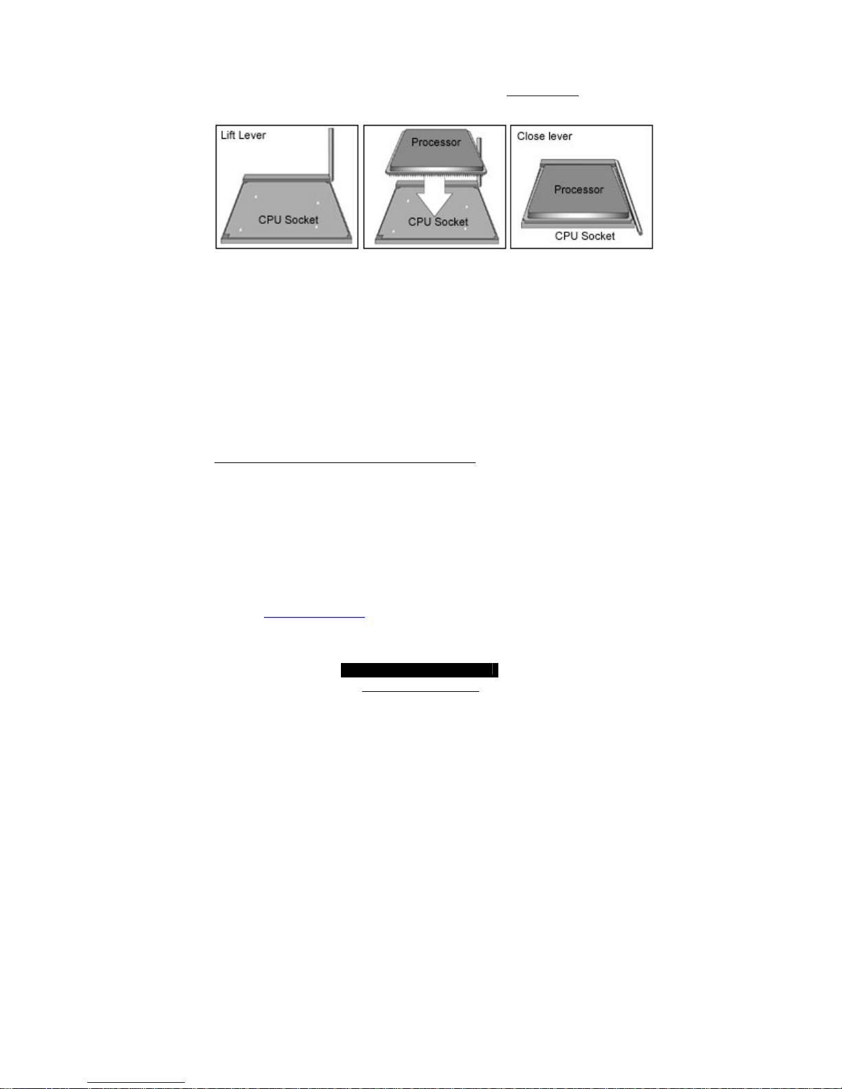
The following diagrams will detail how to install your processor:
The processors you choose to use may not look exactly like the one pictured above, nor
will the socket look exactly the same. The diagram is provided as a visual guide to help you
install socket processors.
1. Lift the lever on the socket until it is approximately 130
o
or as far back as
possible to the socket.
2. Align the processor with the socket. There are keys underneath the processor
just like on memory modules to ensure that they insert in the correct way.
3. Seat the processor firmly into the socket by gently pressing down until the
processor sits flush with the socket.
4. Place the socket lever back down until it snaps into place.
5. Your processor is installed.
Take care when installing processor as it has very fragile con nector pins below the
processor and can bend and break if inserted improperly.
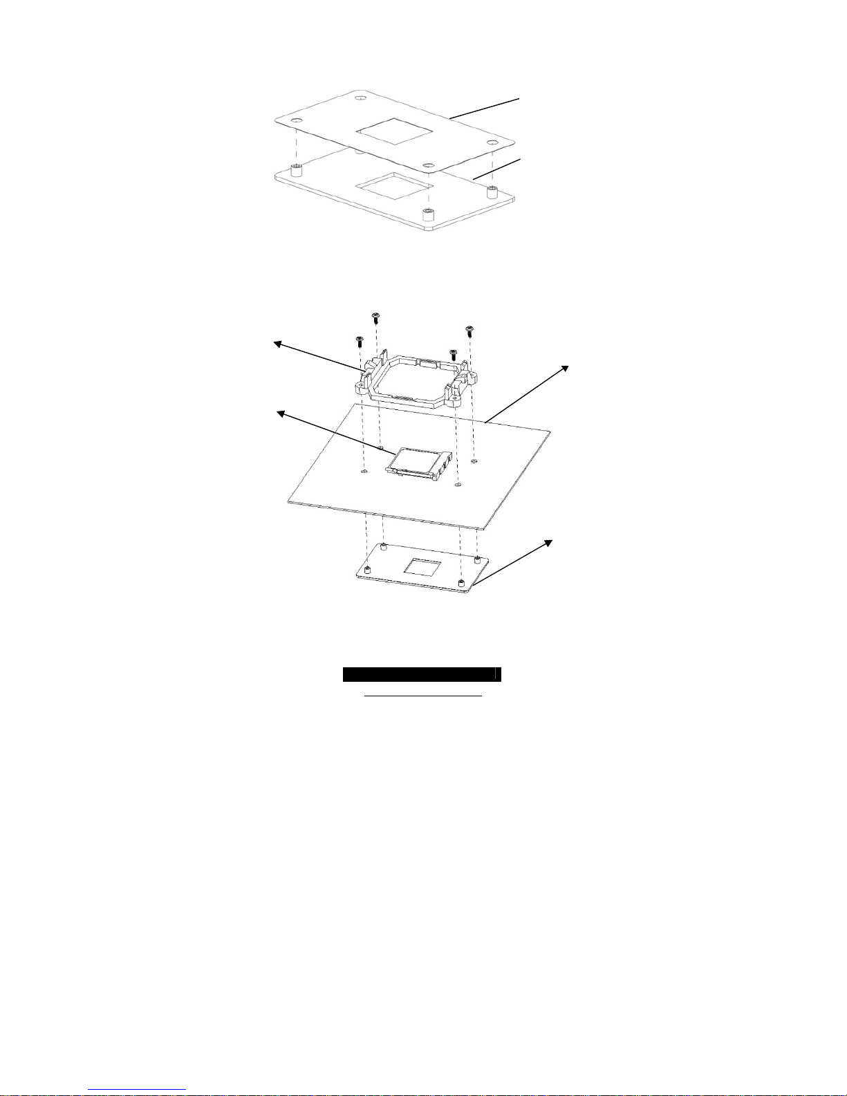
Heatsink Retention Frame and Back Plate Installation
After you have installed the processor, you should proceed to installing the heatsink.
Heatsink will ensure that the processor does not overheat and continues to operate at
maximum performance for as long as you own it. And overheated processor may d amage
the motherboard.
The back plate assembly prevents excessive motherboard flexing in the area near the
processor and provides a base for the installation of the heatsink retention frame and
heatsink.
Because there are many different types of heatsinks available from many different
manufacturers, a lot of them have their own method of installation. For the safest method
of installation and information on choosing the appropriate heatsink, please refer to AMD’s
website at http://www.amd.com
.
http://www.tyan.com
24
The following diagram will illustrate how to install the most common CPU heatsink
retention frame and back plates:
1) Remove the adhesive cover from the back plate.
2) Align the back plate screw bolts to the holes around processor socket on the
back of motherboard.
3) Align the heatsink retention frame to the back plate screw bolts on the front of
motherboard.
4) Insert screws to fasten the retention frame and back plate.
Back plate with
Adhesive insulato
r
Retention Frame
CPU
Back plate
Motherboard
http://www.tyan.com
25
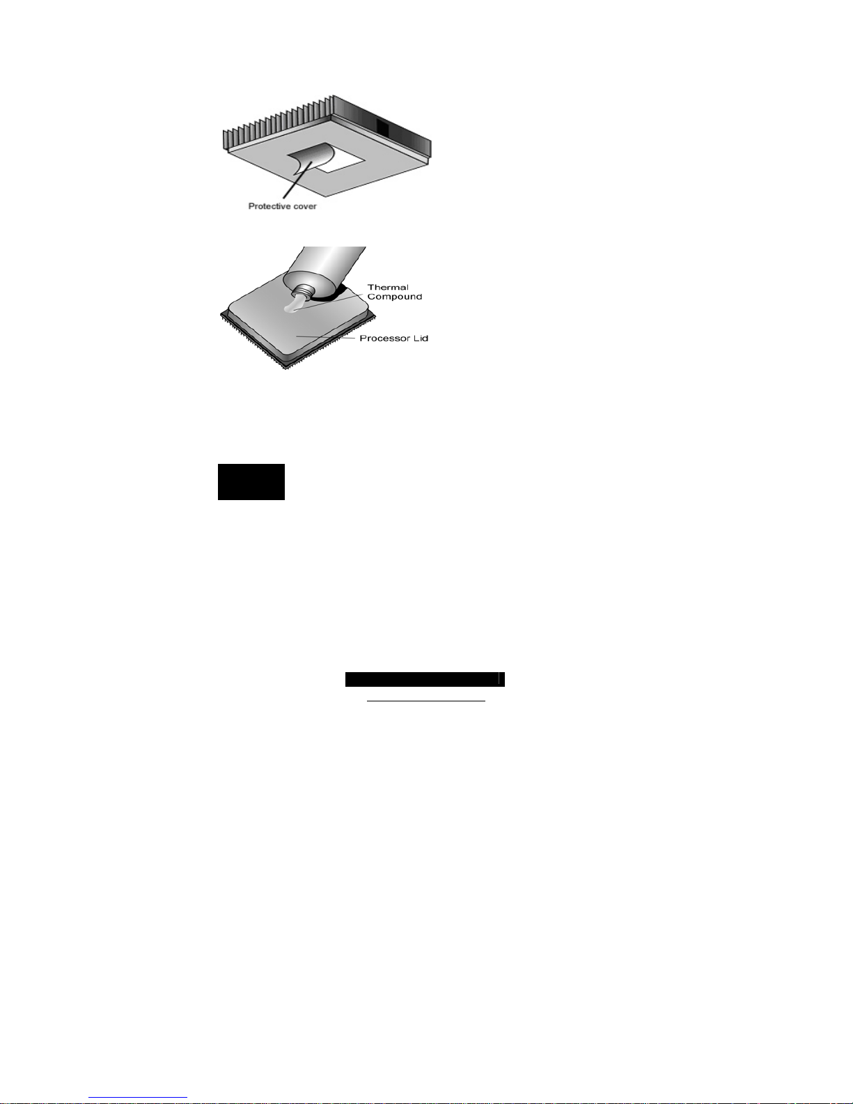
2.22 -- Thermal Interface Material
There are two types of thermal
interface materials designed for use
with the AMD Opteron processor.
The most common material comes as a
small pad attached to the heatsink at
the time of purchase. There should be
a protective cover over the material.
Take care not to touch this material.
Simply remove the protective cover and
place the heatsink on the processor.
The second type of interface material is
usually packaged separately. It is
commonly referred to as ‘thermal
compound’. Simply apply a thin layer
on to the CPU lid (applying too much
will actually reduce the cooling).
NOTE
Always check with the manufacturer of the heatsink & processor to
ensure the Thermal Interface material is compatible with the processor
& meets the manufacturer’s warranty requirements
 Loading...