

TYAN Tomcat i845GV S3098, S3098 User Manual

1
http://www.TYAN.com
Tomcat i845GV
///
S3098
Revision 1.00
Copyright © TYAN Computer Corporation, 2004. All rights reserved. No part of this manual may be
reproduced or translated without prior written consent from TYAN Computer Corp.
All registered and unregistered trademarks and company names contained in this manual are the
properties of their respective owners, including, but not limited to the following.
TYAN, Tomcat i845GV S3098 are trademarks of TYAN Computer Corporation.
Intel, Xeon and the combinations thereof are trademarks of Intel Corporation.
AwardBIOS is a trademark of Phoenix Technology.
Microsoft, Windows are trademarks of Microsoft Corporation.
IBM, PC, AT, PS/2, are trademarks of IBM Corporation.
Promise is a trademark of Promise Technology.
ATI, ATI RAGE are trademarks of ATI Technologies Incorporated.
Winbond is a trademark of Winbond Electronics Corporation.
Information contained in this document is provided by TYAN Computer Corporation and which has
been reviewed for accuracy and reliability before printing, however, TYAN assumes no liability and
disclaims any express or implied warranty relating to sale and/or use of TYAN products including
liability or warranties relating to fitness for a particular purpose or merchantability.
TYAN retains the right to make changes to product descriptions and/or specifications at any time,
without notice. In no event will TYAN be held liable for any direct or indirect, incidental or
consequential damage, loss of use, loss of data or other malady resulting from errors or
inaccuracies of information contained in this document.

2
http://www.TYAN.com
Table of Contents
Before you begin…
Chapter 1: Introduction
1.1 Congratulations!
1.2 Hardware Specifications
Chapter 2: Board Installation
2.01 Board
2.02 Board Jumpers
2.03 Fan1,2,3 Connectors
2.04 CMOS Reset (JP3)
2.05 Front Panel Connector (J9)
2.06 Wake-On-LAN(WOL) (J10)
2.07 Wake-On-Ring(WOR) (J12)
2.08 USB CONNECTOR (J16)
2.09
COM2 CONNECTER (J24)
2.10 LAN2 LINK/ACTIVITY LED (J22)
2.11 LAN1 LINK/ACTIVITY LED (J23)
2.12 SM BUS(J21)
2.13 Mounting the Motherboard
2.14 Installing the Memory
2.15 Memory Installation Procedure
2.16 Installing the Processor and Heatsink
2.17 Attaching Drive Cables
2.18 Installing Add-In Cards
2.19 Connecting External Devices
2.20 LAN LED Scheme
2.21 Installing the Power Supply
2.22 Finishing Up
Chapter 3: BIOS
3.1 Entering Setup
3.2 Standard CMOS Features
3.3 Advanced BIOS Features
3.4 Advanced Chipset Features
3.5 Integrated Peripherals
3.5.1 IDE Device Configuration
3.5.2 PCI Device Configuration
3.5.2.1 Init Display First
3.5.3 Onboard I/O Chip Setup
3.6 Power Management Setup
3.7 PnP/PCI Configuration
3.8 PC Health Status
3.9 Frequency and Voltage Control
3.10 Load fail-safe Defaults
3.11 Load optimized default
3.12 Set Supervisor Password
3.13 Set User Password
3.14 SAVE TO CMOS and (Y/N)
3.15 Quit Without Savjng (Y/N)
Chapter 4: Diagnostics
4.1 Beep Codes
4.2 Flash Utility
Appendix I: Glossary
Technical Support
……………………………………………..Page 3
……………………………………………..Page 4
……………………………………………..Page 4
……………………………………………..Page 4
……………………………………………..Page 5
……………………………………………..Page 6
……………………………………………..Page 7
……………………………………………..Page 8
……………………………………………..Page 8
……………………………………………..Page 8
……………………………………………Page 9
……………………………………………Page 9
……………………………………………Page 9
……………………………………………Page 9
……………………………………………Page 9
……………………………………………Page 9
……………………………………………Page 9
……………………………………………Page 10
……………………………………………Page 11
……………………………………………Page 11
……………………………………………Page 12
……………………………………………Page 13
……………………………………………Page 16
……………………………………………Page 17
……………………………………………Page 17
……………………………………………Page 18
……………………………………………Page 18
……………………………………………Page 19
……………………………………………Page 21
……………………………………………Page 21
……………………………………………Page 23
……………………………………………Page 24
……………………………………………Page 25
……………………………………………Page 26
……………………………………………Page 27
……………………………………………Page 28
……………………………………………Page 28
……………………………………………Page 29
……………………………………………Page 32
……………………………………………Page 33
……………………………………………Page 34
……………………………………………Page 35
……………………………………………Page 35
……………………………………………Page 36
……………………………………………Page 36
……………………………………………Page 37
……………………………………………Page 38
……………………………………………Page 39
……………………………………………Page 39
……………………………………………Page 39
3
http://www.TYAN.com
Before you begin…
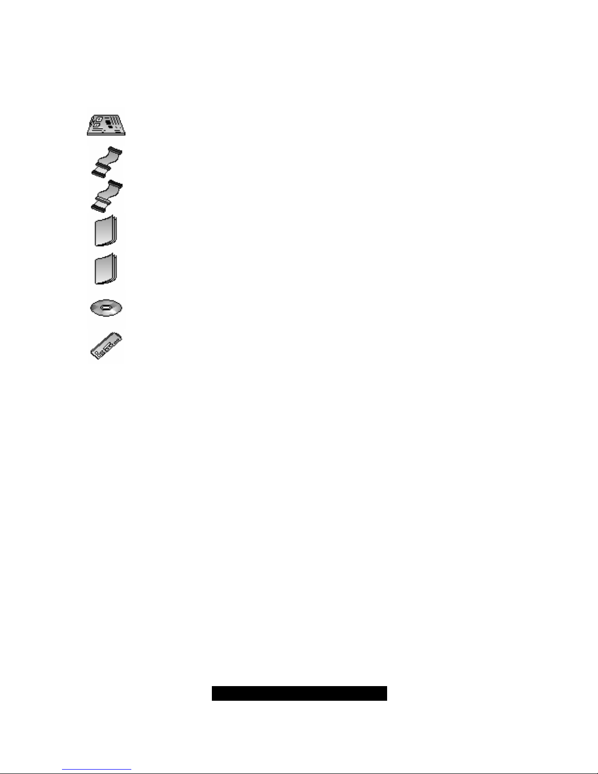
Check the box contents!
The retail motherboard package should contain the following:
1x Tomcat i845GV motherboard
1x 34-Pin floppy drive cable
1x Ultra-DMA-133/100/66 IDE cable
1x Tomcat i845GV User’s Manual
1 x Tomcat i845GV Quick Reference
1x TYAN driver CD
1x I/O shield
If any of these items are missing, please contact your vendor/dealer for replacement before
continuing with the installation process.

4
http://www.TYAN.com
Chapter 1: Introduction
1.1 – Congratulations!
You have just bought one of the most advanced platforms suited for digital content creation,
productivity and 3D gaming applications. The Tomcat i845GV is based on Intel’s 845GV chipset,
supporting the Intel Pentium 4 or Celeron Processor with 400/533MHz FSB, DDR memory, Intel
Extreme Graphics, and more. These features enable breakthrough performance for today’s rapidly
developing multimedia applications.
Visit TYAN’s Website at http://www.TYAN.com
. There you can find information on all of TYAN’s
products with FAQ’s, distributor’s list and BIOS setting explanations.
1.2 – Hardware Specifications.
Processor
Single ZIF PGA478 Socket
Intel mobile Pentium4-M/Celeron, Intel
P4
“Northwood” and “Prescott” processor
400/533MHz FSB support
Expansion Slots
2 32Bit/33MHz PCI 2.3(5V) Expansion Slots
Chipset
Intel 845GV chipset
Intel ICH4
ITE IT8712F LPC I/O chip
System Management
Three 3-pin Fan headers and the CPU fan with
tachometer for auto fan speed control
Temperature and voltage monitoring
3-pin Wake-On-Ring header
3-pin Wake-On-LAN header
Memory
Single memory channel
Supports up to two PC1600/2100/2700 DIMM
Up to 2GB of unbuffered Non-ECC memory
Integrated IDE
Dual channel master mode support up to four
IDE devices
Support for ATA-100/66/33 IDE drives and
ATAPI compliant devices
Back Panel I/O Ports
Stacked PS/2 Mouse & Keyboard ports
Stacked four USB 2.0 ports
One 9-pin UART Serial port
One 15-pin VGA port
One 25-pin SPP/ECP/EPP parallel port
Two RJ45 10/100 Base-T port
Integrated I/O Interfaces
One Floppy connector for up to two drives
Two IDE connectors for up to four IDE devices
One USB 2.0 Ports (via optional cable)
One serial port pin header for Com2
Headers for LAN LED/I
2
C/Chassis intrusion
Headers for CPU/Power Supply/Chassis
Fans
Tyan 2 x 9 front panel connector
Integrated LAN Controllers
Two Intel 82551QM 10/100* Base-T LAN
controllers (Optional 82541 GbE controller)
Operating at 32bit/33MHz PCI bus
Integrated Graphics
Intel Extreme Graphics Core
Optimized 256-bit BLT engine
Up to 2.1GB/s data access in UMA
configuration
Supports analog monitor up to
2048x1536@60Hz
BIOS
Award BIOS 4Mbit Flash
Supports APM 1.2 & ACPI 1.0
Auto detection of memory size
Auto configuration of IDE hard disk types
User settings of hardware monitoring
Multiple boot options
Power Management: S1, S3, S4
Power
On board 3-phase VRM
ATX 12V (20-pin + 4-pin) power connectors
Form Factor
Flex ATX footprint
9” x 7.5” (228.6cm x 190.5mm)
Regulatory
FCC Class B (Declaration of Conformity)
European Community CE (Declaration of
Conformity)

5
http://www.TYAN.com
Chapter 2: Board Installation
Installation
You are now ready to install your motherboard. The mounting hole pattern of the Tomcat i845GV
matches the FlexATX system board specifications. Your chassis should support a standard
FlexATX motherboard form factor.
How to install our products right…. the first time!
The first thing you should do is read this user’s manual. It contains important information that will
make configuration and setup much easier. Here are some precautions you should take when
installing your motherboard:
(1) Ground yourself properly before removing your motherboard from the antistatic bag.
Unplug the power from your computer power supply and then touch a safely grounded
object to release static charge (i.e. power supply case). For the safest conditions, TYAN
recommends wearing a static safety wrist strap.
(2) Hold the motherboard by its edges and do not touch the bottom of the board, or flex the
board in any way.
(3) Avoid touching the motherboard components, IC chips, connectors, memory modules,
and leads.
(4) Place the motherboard on a grounded antistatic surface or on the antistatic bag that the
board was shipped in.
(5) Inspect the board for damage.
The following pages include details on how to install your motherboard into your chassis, as well
as installing the processor, memory, disk drives and cables.
NOTE DO NOT APPLY POWER TO THE BOARD IF IT HAS BEEN DAMAGED
6
http://www.TYAN.com
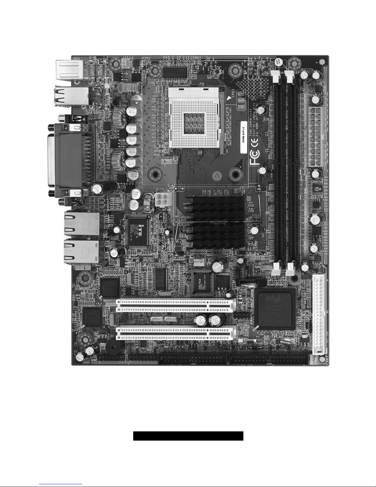
2.01 – Board
The following is an image of the Tomcat i845GV S3098.
The above photograph is purely representative. Due to engineering updates and new board
revisions, certain components may change and or be repositioned. The picture above may
or may not look exactly like the board you received.
The following page includes details on the vital components of this motherboard.
7
http://www.TYAN.com
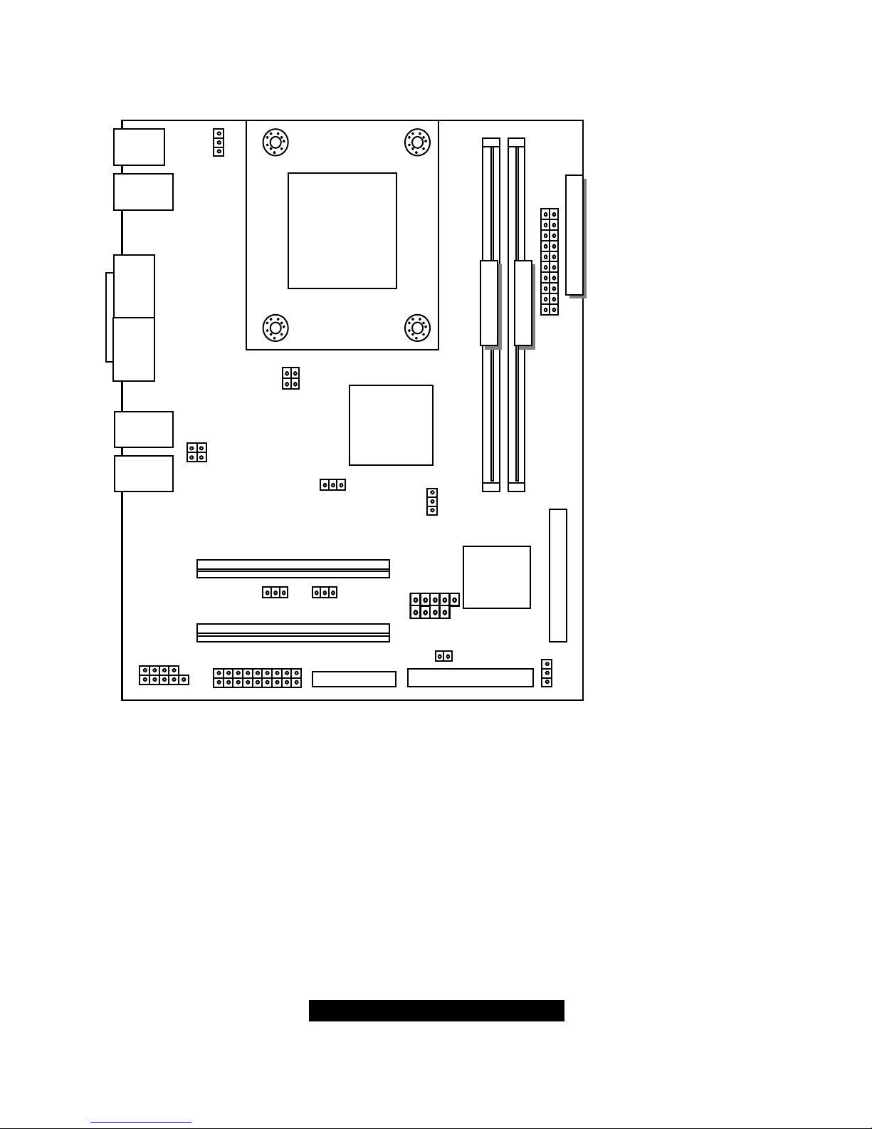
2.02 – Board Jumpers
This jumper diagram is representative of the latest board revision available at the time of
publishing. The board you receive may or may not look exactly like the above diagram.
PS/2
USB
Serial Port
VGA Port
Parallel Port
FAN1
J23(LAN1 Lnk/Act LED)
J22(LAN2 Lnk/Act LED)
DDR DIMM 1
DDR DIMM 2
20
p
in Power Su
pp
l
y
FAN2
FAN3
J21(SM BUS)
J24(COM2)
J9(Front Panel)
J10(WOL) J12(WOR)
J16(USB2)
JP3(CMOS Reset)
LAN1
LAN2
1
1
1
4pin-Power Supply
1
8
http://www.TYAN.com
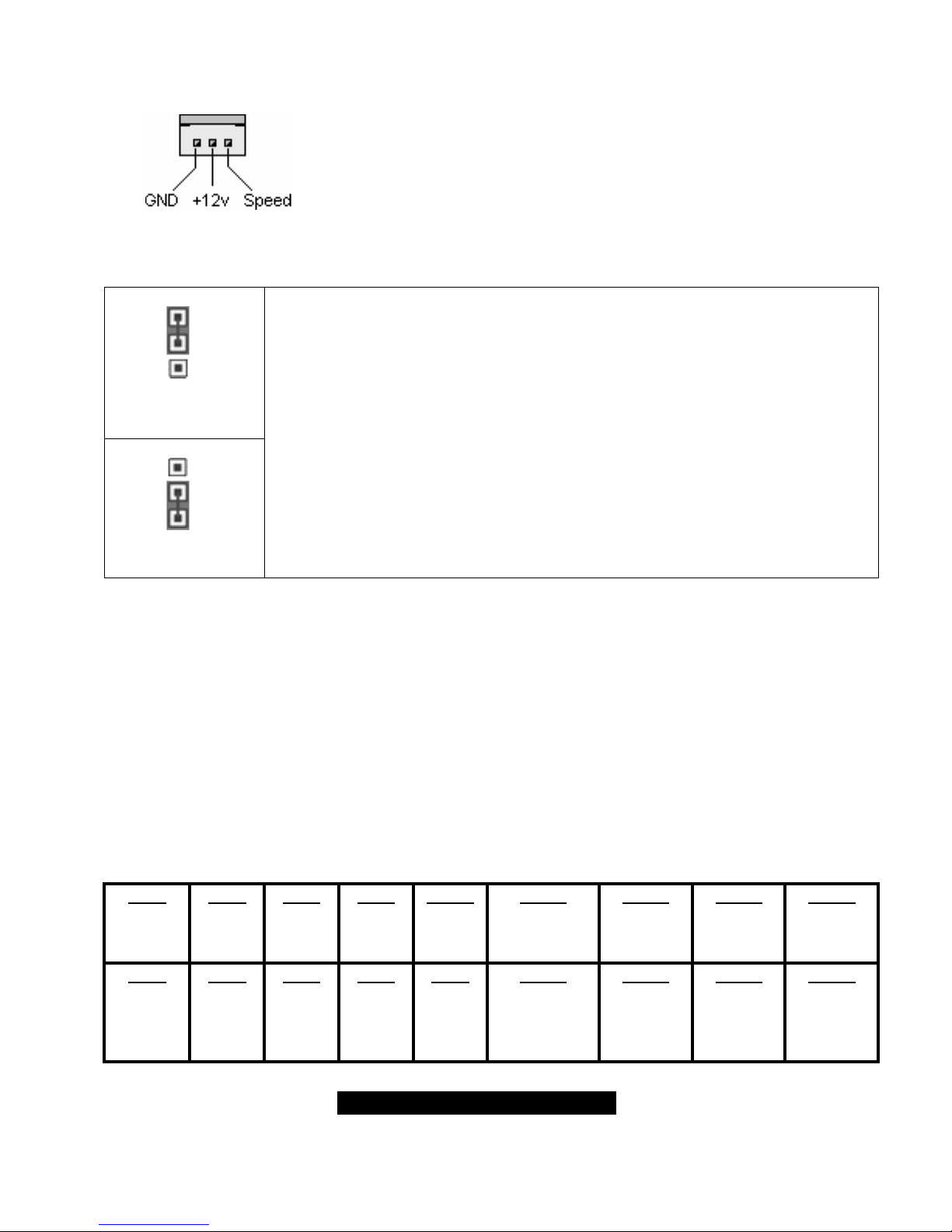
2.03 – Fan1, Fan2, Fan3 Connectors
Use these headers to connect cooling fans, both chassis and
processor fans, to your motherboard. Cooling fans help keep the
system more stable and operating reliably for its product life.
(NOTE: Please refer to< Chapter3: BIOS setup-3.8 PC Health
Status> for ”Auto Fan1 Power Control” function.
2.04 – CMOS Reset (JP3)
1
Clear CMOS
1
Default
2,3: Clear CMOS
1,2: Default
Connect pins 2 and 3 together to reset the CMOS settings in case an incorrect
setting causes system instability or you have forgotten your system/setup
password or have just flashed your BIOS.
Power off the system and disconnect the power supply.
- Close pins 2 and 3 on JP3
- Wait about 5 seconds
- Close pins 1 and 2 on JP3
- Reconnect the power supply and power on the system
2.05 – Front Panel Connector (J9)
Your chassis will usually come with connectors to install onto the motherboard, such as HDD and
Power LEDs. The Front Panel Connector has been implemented for such purposes.
J9 Pinout:
HDD LED: 1,3
Power LED: 2,4
Reset Switch: 5,7
Power/Sleep Switch: 6,8
Infrared: 9.11,13,15,
Speaker: 12,14,16,18
Pin 2
Power
LED+
Pin 4
Power
LED-
Pin 6
PWR+
Pin 8
GND
Pin 10
NC
Pin 12
Speaker+
Pin 14
NC
Pin 16
NC
Pin 18
Speaker-
Pin 1
HDD
LED+
Pin 3
HDD
LED-
Pin 5
GND
Pin 7
Reset
SW+
Pin 9
+5V
Pin 11
IR RX
Pin 13
GND
Pin 15
IRTX
Pin 17
NC
9
http://www.TYAN.com
2.06 – Wake-On-LAN(WOL) (J10)
Plugging your LAN card cable into J10 enables the Wake-On-LAN feature. This
automatically resumes the system power when the LAN port receives an
incoming signal during power-saving mode.
2.07 – Wake-On-Ring(WOR) (J12)
Similarly to the Wake-On-LAN, plugging your modem into J12 enables the
Wake-On-Ring feature. This automatically resumes the system power when the
modem receives an incoming signal during power-saving mode.
2.08 – USB CONNECTOR (J16)
Pins grouped together:
1,2: VCC
3,4: USB +
5,6: USB –
7,8,10: GND
Pin 2
VCC
Pin 4
USB -
Pin 6
USB +
Pin 8
GND
Pin 10
GND
Pin 1
VCC
Pin 3
USB -
Pin 5
USB +
Pin 7
GND
2.09- COM2 CONNECTER (J24)
Pin 2
DSR
Pin 4
RTS
Pin 6
CTS
Pin 8
RI
Pin 1
DCD
Pin 3
RX
Pin 5
TX
Pin 7
DTR
Pin 9
GND
2.10- LAN2 LINK/ACTIVITY LED (J22)
1:LANLED+ 2:LANLED-
2.11- LAN1 LINK/ACTIVITY LED (J23)
1:LANLED+ 2:LANLED-
2.12- SM BUS (J21)
1:SMB CLK 2:SMB DAT
10
http://www.TYAN.com
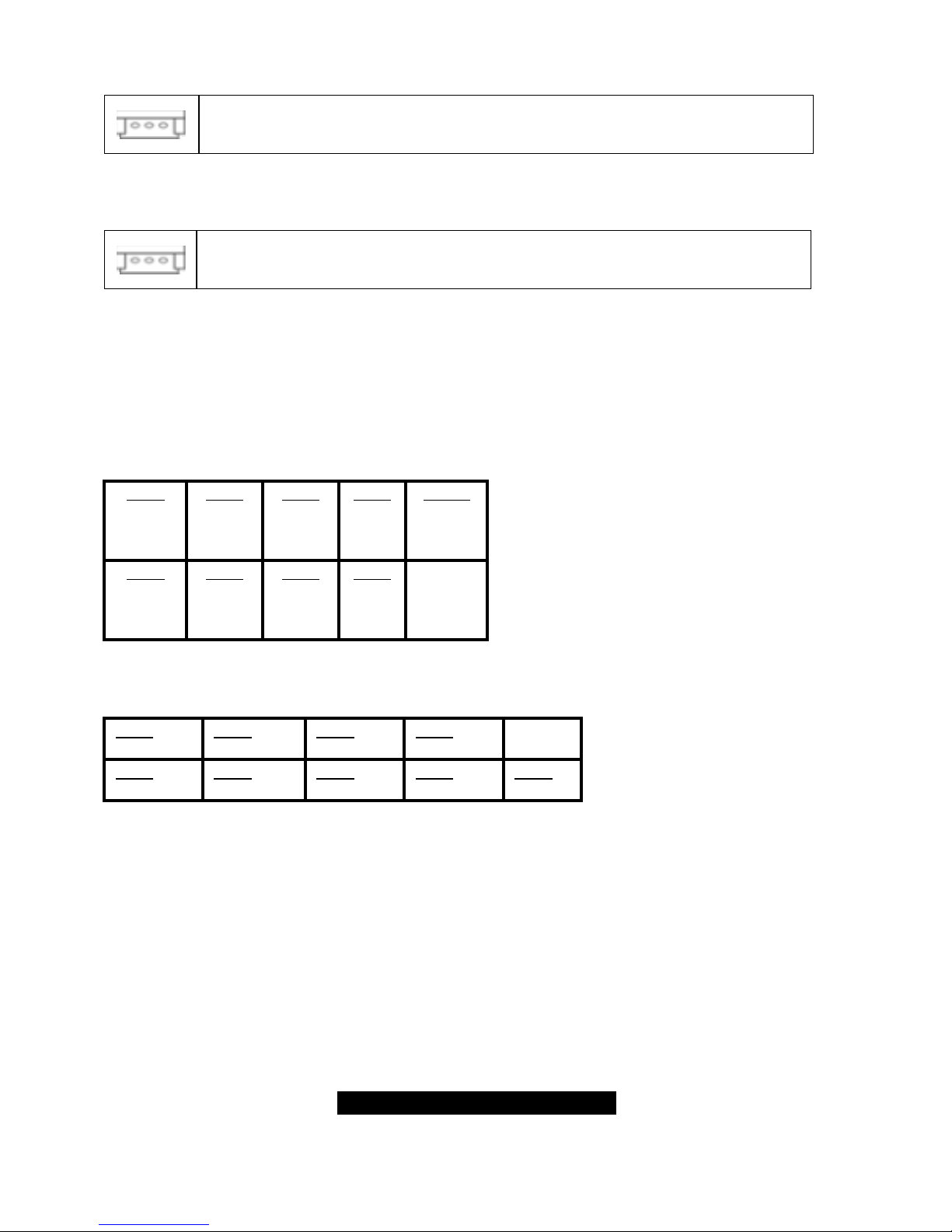
2.13 – Mounting the Motherboard
Before installing your motherboard, make sure your chassis has the necessary motherboard
support studs installed. These studs are usually metal and are gold in color. Usually, the chassis
manufacturer will pre-install the support studs. If you’re unsure of stud placement, simply lay the
motherboard inside the chassis and align the screw holes of the motherboard to the studs inside
the case. If there are any studs missing, you will know right away since the motherboard will not
be able to be securely installed.
Some chassis’ include plastic studs instead of metal. Although the plastic studs are usable, TYAN
recommends using metal studs with screws that will fasten the motherboard more securely
in place.
Below is a chart detailing what the most common motherboard studs look like and how they
should be installed.
TIP: Use metal studs if possible, as they hold the motherboard into place more securely than
plastic standoffs.
11
http://www.TYAN.com
2.14 – Installing the Memory
Before attempting to install any memory, make sure that the memory you have is compatible with
the motherboard as well as the processor. For example, while PC1600 DDR modules are
compatible with all DDR based motherboards, they will not work if you are required to run the
motherboard and processor buses at 133MHz. For this, PC2100 DDR modules are required.
Critically important is whether you’re using the recommended memory for the current board you
have. For this information, please check TYAN’s web site at: www.TYAN.com
.
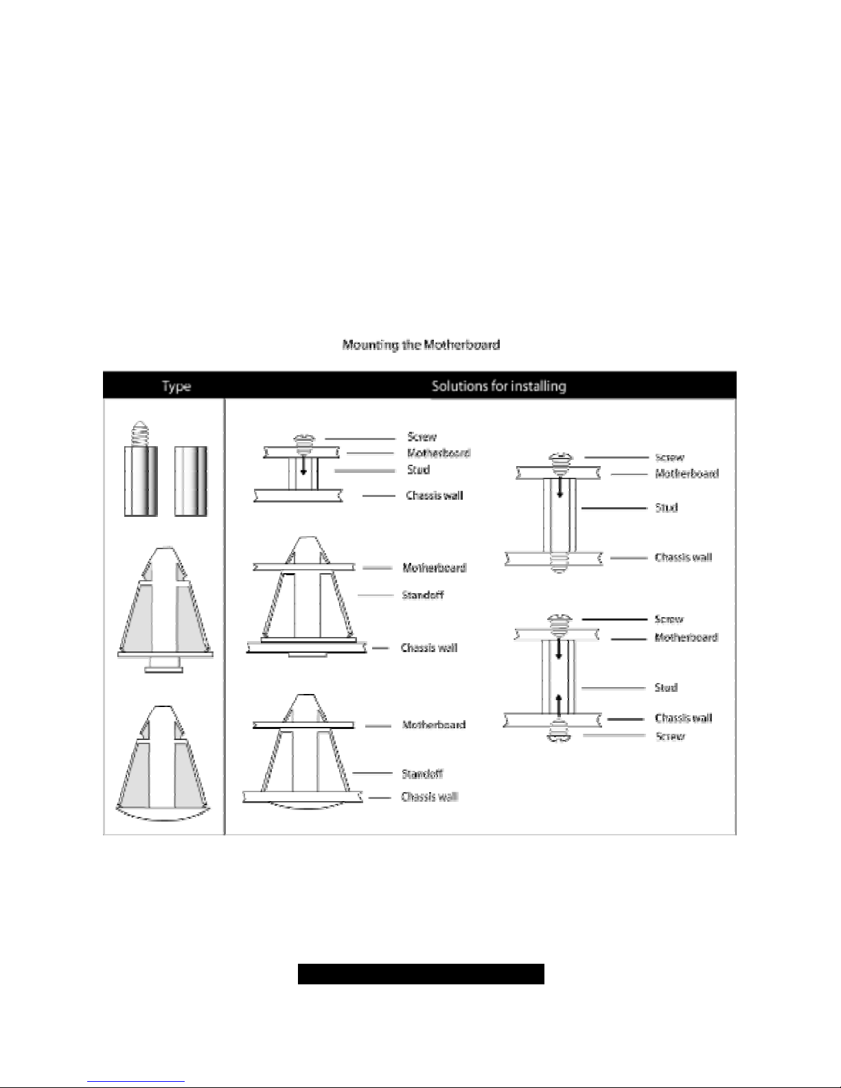
The following diagram shows the types of RAM modules you may encounter.
Use only 184-pin unbuffered non-ECC memory for S3098.
Unbuffered
Non-ECC
= 8 Chips
Unbuffered
ECC
= 9 Chips
Note: The Tomcat i845GV has two DIMM sockets, which supports a maximum of four banks of
DDR memory (only supports 64 MB, 128 MB, 256 MB, 512MB and 1GB technologies for x8 and
x16 devices.)
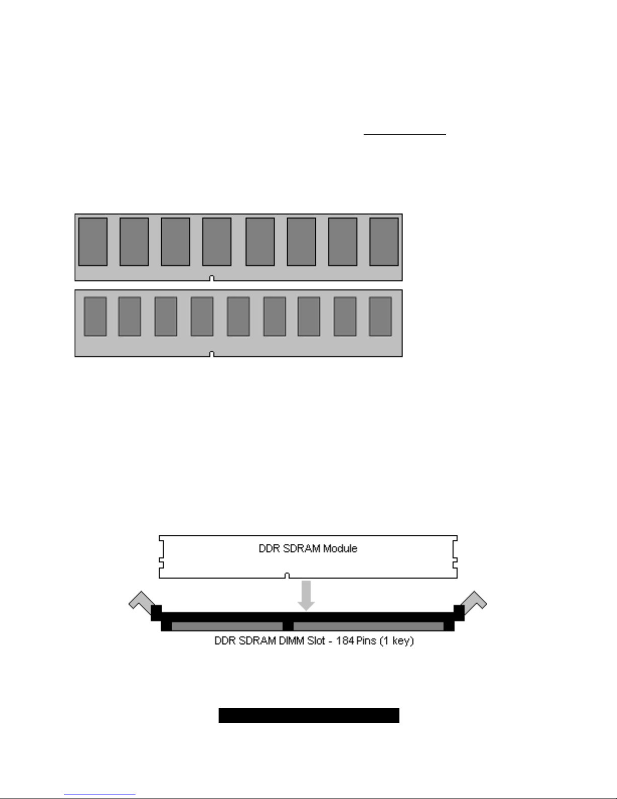
2.15 – Memory Installation Procedure
When you install the memory modules, make sure the module aligns properly with the memory
slot. The modules are keyed to ensure that it is inserted only one way. The method of installing
memory modules are detailed by the following diagrams.
12
http://www.TYAN.com
Once the memory modules are firmly seated in the slot, two latches on either side will close and
secure the module into the slot. Sometimes you may need to close the latches yourself.
To remove the memory module, simply push the latches outwards until the memory module pops
up. Then simply remove the module.
NOTE
Due to the PCI v2.2 specifications, you MUST unplug the power connector to the
motherboard before performing system hardware changes to avoid having your
motherboard boot-up automatically.
2.16 – Installing the Processor and Heatsink
Your brand new Tomcat i845GV supports the latest processor technologies from Intel. Check
TYAN’s website for latest processor support:
http://www.TYAN.com
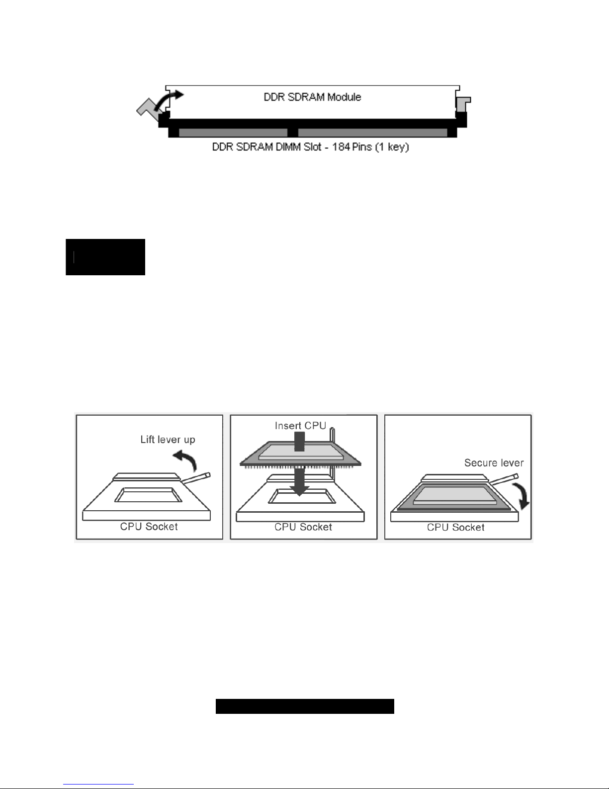
The following diagrams will detail how to install your processor:
The processor you choose to use may not look exactly like the one pictured above, nor will the
socket look exactly the same. For example, your processor may appear to be in a different color
and have different markings on it. The diagram is provided as a visual guide to help you install the
processor.
1. Lift the lever on the socket until it is approximately 90
o
or as far back as possible
to the socket.
2. Align the processor with the socket. There are keys underneath the processor just like
on memory modules to ensure that they insert the correct way.
13
http://www.TYAN.com
3. Seat the processor firmly into the socket by gently pressing down until the processor
sits flush with the socket.
4. Place the socket lever back down until it snaps into place.
5. Your processor is installed.
Take care when installing Pentium 4 processors as they have very fragile connector pins
below the processor and can bend and break if inserted improperly.
Heatsink Installation
After you are done installing the processor, you should proceed to installing the heatsink. The
heatsink will ensure that the processor does not overheat, and will continue to operate at
maximum performance. An overheated processor is also dangerous to the long-term reliability of
the motherboard.
Because there are many different types of heatsinks available from many different manufacturers,
many have their own method of installation. For the safest method of installation and information
on choosing the appropriate heatsink, please refer to TYAN’s website: http://www.TYAN.com
.
Finishing Installing the Heatsink
After you finish installing the heatsink onto the processor and socket, attach the end wire of the
fan (which should already be attached to the heatsink) to the motherboard. The following diagram
illustrates how to connect fans onto the motherboard.
After you’re finished installing all the fans you can connect your drives (hard drives, CD-ROM
drives, etc.) to your motherboard.
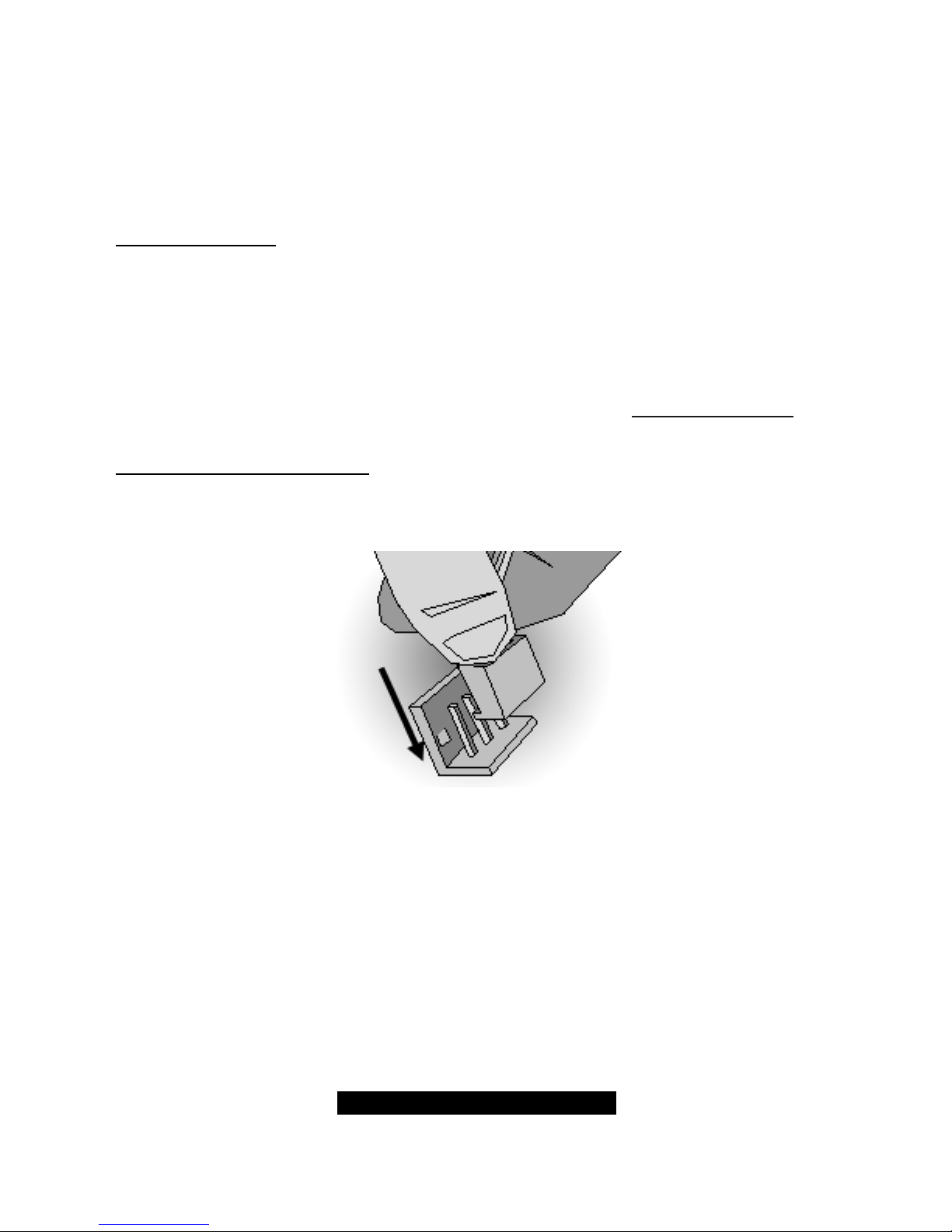
2.17 – Attaching Drive Cables
Attaching IDE cables to your drives is simple because they only go in one way. TYAN
motherboards have two on-board IDE channels for you to use, each supporting two drives. There
is a white and a black IDE connector on your motherboard. The black connector is the Primary
IDE channel and the white connector is the Secondary IDE channel.
Attaching IDE cables to the IDE connectors is illustrated below:
14
http://www.TYAN.com
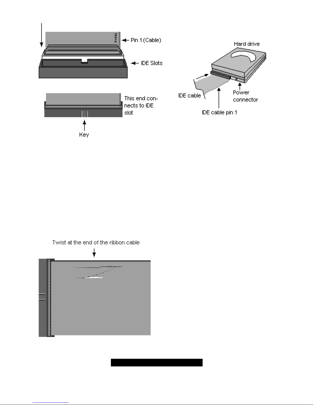
Simply plug in the BLUE END of the IDE cable into the motherboard IDE connector, and the other
ends into the drive(s). Each standard IDE cable has three connectors, two being close to each
other. The BLUE connector that is far on its own is the end that plugs into the motherboard
whereas the other two connectors are used to connect to drives.
TIP: Pin 1 on the IDE cable (usually denoted by a colored wire) faces the drive’s power
connector.
Floppy Drives
Attaching floppy diskette drives are done in a similar manner to hard drives. See the picture below
for an example of a floppy cable. Most of the current floppy drives on the market require that the
cable be installed with the colored stripe positioned next to the power connector. In most cases,
there will be a key pin on the cable which will force a proper connection of the cable.
The first floppy drive (sometimes denoted as
A:) is usually attached to the end of the cable
with the twist in it. Drive B: is usually connected
to the second or third connector in the cable
(the second or third connector after you install
Drive A:).
Refer to your floppy drive’s installation
instructions (if available), or contact your dealer
if you are unsure about how to attach the
floppy drive(s). Remember, you can only have
2 floppy drives connected at any given time.
 Loading...