

TYAN Thunder n3600B S2927, S2927 User Manual

http://www.tyan.com
1
Thunder n3600B
///
S2927
Version 1.0
Copyright
Copyright © TYAN Computer Corporation, 2006. All rights reserved. No part of
this manual may be reproduced or translated without prior written consent from
TYAN Computer Corp.
Trademark
All registered and unregistered trademarks and company names contained in
this manual are property of their respective owners including, but not limited to
the following.
TYAN, Thunder n3600B are trademarks of TYAN Computer Corporation.
AMD, Opteron, and combinations thereof are trademarks of AMD Corporation.
AMI, AMI BIOS are trademarks of AMI Technologies.
Microsoft, Windows are trademarks of Microsoft Corporation.
SuSE,is a trademark of SuSE AG.
Marvell® is a trademark of Broadcom Corporation and/or its subsidiaries
XGI and XG20 are trademarks of XGI Corporation
nVIDIA, nForce are trademarks of NVIDIA Corporation.
Notice
Information contained in this document is furnished by TYAN Computer
Corporation and has been reviewed for accuracy and reliability prior to printing.
TYAN assumes no liability whatsoever, and disclaims any express or implied
warranty, relating to sale and/or use of TYAN products including liability or
warranties relating to fitness for a particular purpose or merchantability. TYAN
retains the right to make changes to product descriptions and/or specifications
at any time, without notice. In no event will TYAN be held liable for any direct or
indirect, incidental or consequential damage, loss of use, loss of data or other
malady resulting from errors or inaccuracies of information contained in this
document.

http://www.tyan.com
2
Table of Contents
Check the box contents! Page 3
Chapter 1: Introduction
1.1 Congratulations Page 5
1.2 Hardware Specifications Page 5
Chapter 2: Board Installation
2.1 Board Image Page 8
2.2 Block Diagram Page 9
2.3 Board Parts, Jumpers and Connectors Page 10
2.4 Tips on Installing Motherboard in Chassis Page 22
2.5 Installing the Processor(s) Page 23
2.6 Installing the Memory Page 28
2.7 Attaching Drive Cables Page 31
2.8 Installing Add-In Cards Page 33
2.9 Installing Graphic Cards and SLI Bridge Page 34
2.10 Connecting External Devices Page 35
2.11 Installing the Power Supply Page 36
2.12 Finishing Up Page 36
Chapter 3: BIOS Setup
3.1 About the BIOS Page 37
3.2 BIOS Menu Bar Page 37
3.3 Setup Basics Page 38
3.4 Getting Help Page 38
3.5 In Case of Problems Page 38
3.6 BIOS Main Menu Page 39
3.7 Advanced Menu Page 40
3.8 PCI/PnP Menu Page 61
3.9 Boot Menu Page 63
3.10 Security Menu Page 67
3.11 Chipset Menu Page 68
3.12 Exit Menu Page 70
Chapter 4: Diagnostics
4.1 Beep Codes Page 71
4.2 Flash Utility Page 71
4.3 AMIBIOS Post Code Page 77
Appendix: SMDC Information Page 79
Glossary Page 81
Technical Support Page 87
http://www.tyan.com
3
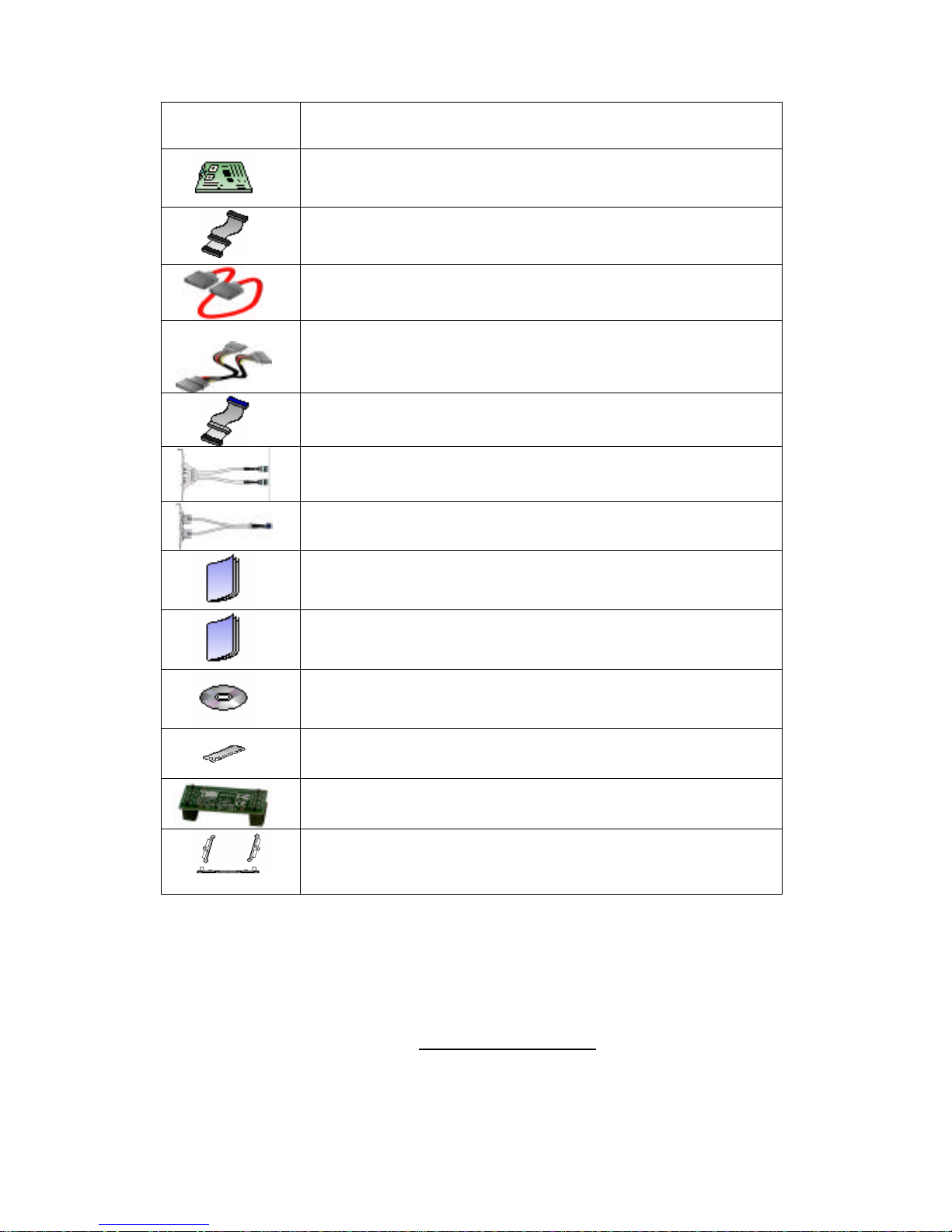
Check the box contents!
Item S2927
1x S2927 motherboard
1x 34-Pin floppy drive cable
6 x SATA cable
3 x SATA Drive Power Adapter
1 x Ultra-DMA-100/66 IDE cable
1 x IEEE1394a Cable (S2927A2NRF only)
1 x USB2.0 cable
1 x S2927 User’s Manual
1 x S2927 Quick Reference guide
1 x TYAN driver CD
1 x I/O shield
1 x SLI bridge (S2927A2NRF only)
2 x CPU Retention Frame and Back Plate

http://www.tyan.com
4

http://www.tyan.com
5
Chapter 1: Introduction
1.1 - Congratulations
You have purchased one of the most powerful server solutions. The Thunder
n3600B (S2927) is a flexible AMD64 platform for multiple applications, based on
NVIDIA nForce Pro3600 and SMSC SCH5017 chipsets.
Designed to support AMD® Opteron™ 2000 series processors and DDRII-667
memory, the S2927 with integrated Dual Gigabit Ethernet LAN, built-in 16MB
XGI XG20TM video and six serial ATA ports, is ideal for CPU, memory, and
video intensive applications such as CAD, Graphics Design, and High
Bandwidth Video Editing, etc.
Remember to visit TYAN’s Website at http://www.TYAN.com. There you can
find information on all of TYAN’s products with FAQs, online manuals and BIOS
upgrades.
1.2 - Hardware Specifications
Processor
•Dual 1207-pin ZIF sockets
•Supports up to two AMD Socket F
Opteron 2000 series processors
•Up to 1.0GHz Hyper-Transport link
support
Expansion Slots
•One (1) x16 PCI-E (PCI-E1)
•One (1) x16 PCI-E with x8
bandwisth (PCI-E2)
•Three 32-bit, 33MHz PCI v2.3
slots (PCI1~PCI3)
•Total five usable expansion slots
Chipset
•nVIDIA nForce Pro 3600
•SMSC SCH5017
Memory
•Dual memory channels
•Supports 8x DDRII-667/533/400
registered, ECC DIMMs
Integrated LAN Controllers
•Two nForce Pro 3600 integrated
MAC with two Marvell 88E1116
single port Gigabit Ethernet PHY
- Integrated TCP offload Engine
(TOE)
- IEEE802.3 compliant, WOL/PXE
support
- Pin header for front panel LAN
LED
Integrated Audio
(S2927A2NRF only)
•Realtek ALC262 audio CODEC
•HD Audio 1.0 compliant
•2 x 5 pin header for front panel
audio connector
•CD_IN connector
Integrated PCI 1394
(S2927A2NRF only)
•VIA VT6307/6308 PCI FireWire
(1394) controller
•Two IEEE1394 ports (via cable)

http://www.tyan.com
6
System Management
•SMSC SCH5017 w/ 2x
EMC6D103
•2x CPU FAN & 2x 4-pin system
Fan headers, w/ tachometer input
and w/ auto fan control
•Temperature and voltage
monitoring
•Watchdog timer
•Port 80 code display LED
Integrated PCI IDE
•Single channel master mode
support up to two IDE devices
•Support for ATA-133/100/66/33
IDE drives and ATAPI compliant
devices
Integrated 2D/3D PCI Graphics
(S2927G2NR only)
•XGI Volari (XG20)
•16MB frame buffer memory
Integrated Serial ATA II
•Three serial ATA II Host
controllers embedded
•Supports up to 6 serial ports
running at 3.0Gb/s per direction
per channel
•Serial ATA II specification
compliant
•nVIDIA MediaShieldTM supports for
RAID 0, 1, 0+1, 5, JBOD
•HDD LED connector
Integrated I/O Interface
•One (1) floppy connector
•Four (4) USB 2.0 ports (via cable)
•One (1) COM port (via cable)
•Tyan 2x9 front panel pin header
•One (1) parallel pin header
Form Factor
•ATX footprint, 10.2” x 12.0”
(259mmx305mm)
Back Panel I/O Ports
•Stacked PS/2 mouse & keyboard
ports
•One (1) COM1 connector
•One (1) 15-pin VGA port
•3 audio jacks (from bottom: line
out <green>, line in <blue>, MIC
<pink>) (S2927A2NRF version
only)
•2 double-decked USB2.0 ports
and one RJ45 (2x Marvell
88E1116 single port GbE PHy +
nVIDIA MAC) 10/100/1000 BaseT port with link/activity LED
Server Management
•M3291, IPMI 2.0 Remote System
Mgmt card
•Renesas H8S2167 BMC controller
•BT, KCS, Logging support
•IPMI-over-LAN
•Remote power on/off and reset
BIOS
•AMI BIOS 8Mbit Flash
•Supports ACPI 2.0
•PnP, DMI2.0, WfM 2.0 power
management
Power
•EPS12V support, on board 4phase VRD
•Universal 24-pin + 8-pin power
connectors
•4-pin auxiliary power connector
Regulatory
•FCC Class B (Declaration of
Conformity)
•CE (Declaration of Conformity)

http://www.tyan.com
7
Chapter 2: Board Installation
You are now ready to install your motherboard. The mounting hole pattern of
the Thunder n3600B S2927 matches the ATX specification. Before continuing
with installation, confirm that your chassis supports an ATX motherboard.
How to install our products right… the first time
The first thing you should do is reading this user’s manual. It contains important
information that will make configuration and setup much easier. Here are some
precautions you should take when installing your motherboard:
(1) Ground yourself properly before removing your motherboard from the
antistatic bag. Unplug the power from your computer power supply and
then touch a safely grounded object to release static charge (i.e. power
supply case). For the safest conditions, TYAN recommends wearing a
static safety wrist strap.
(2) Hold the motherboard by its edges and do not touch the bottom of the
board, or flex the board in any way.
(3) Avoid touching the motherboard components, IC chips, connectors,
memory modules, and leads.
(4) Place the motherboard on a grounded antistatic surface or on the
antistatic bag that the board was shipped in.
(5) Inspect the board for damage.
The following pages include details on how to install your motherboard into your
chassis, as well as installing the processor, memory, disk drives and cables.
NOTE
DO NOT APPLY POWER TO THE BOARD IF IT HAS BEEN
DAMAGED
http://www.tyan.com
8
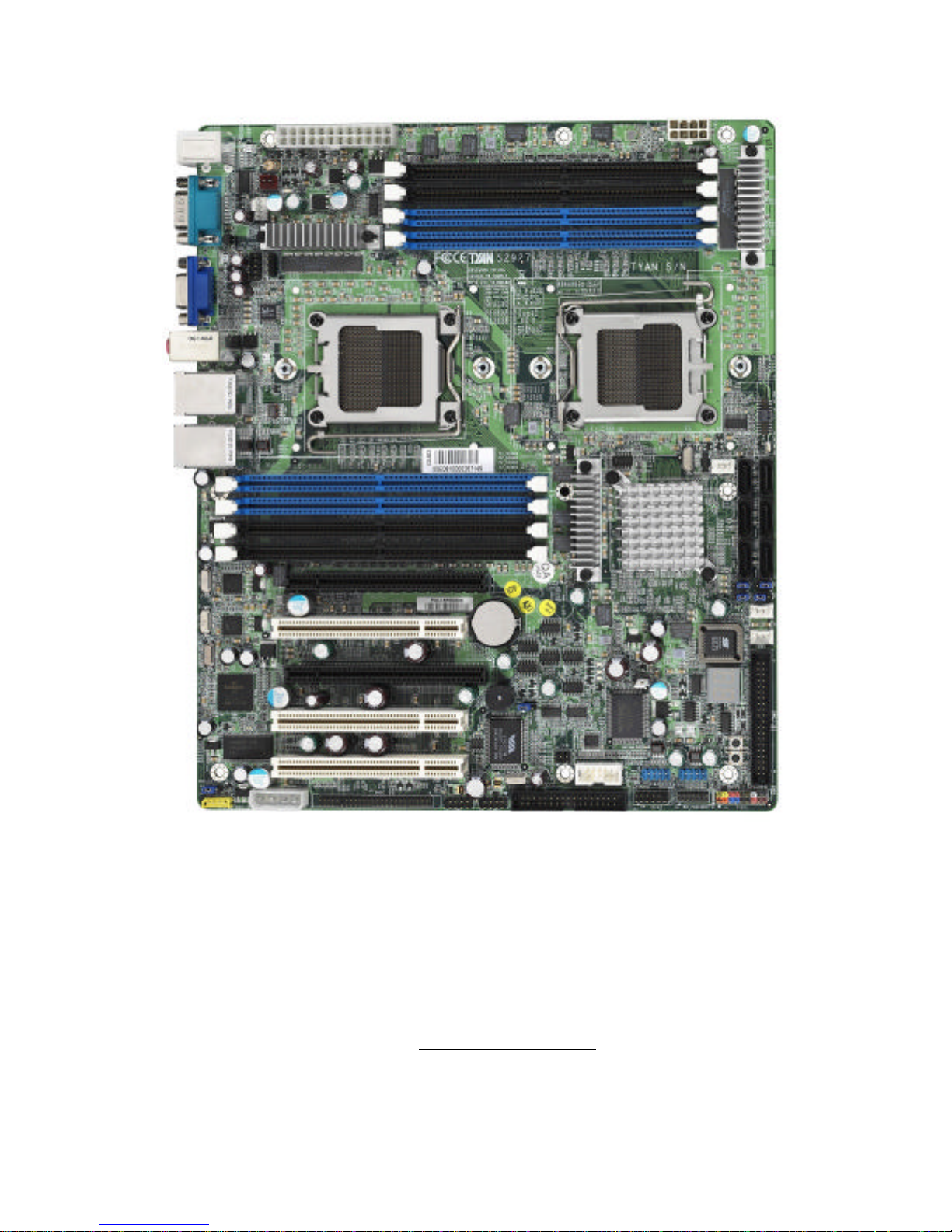
2.1- Board Image
This picture is representative of the latest board revision available at
the time of publishing. The board you receive may or may not look
exactly like the above picture.
http://www.tyan.com
9
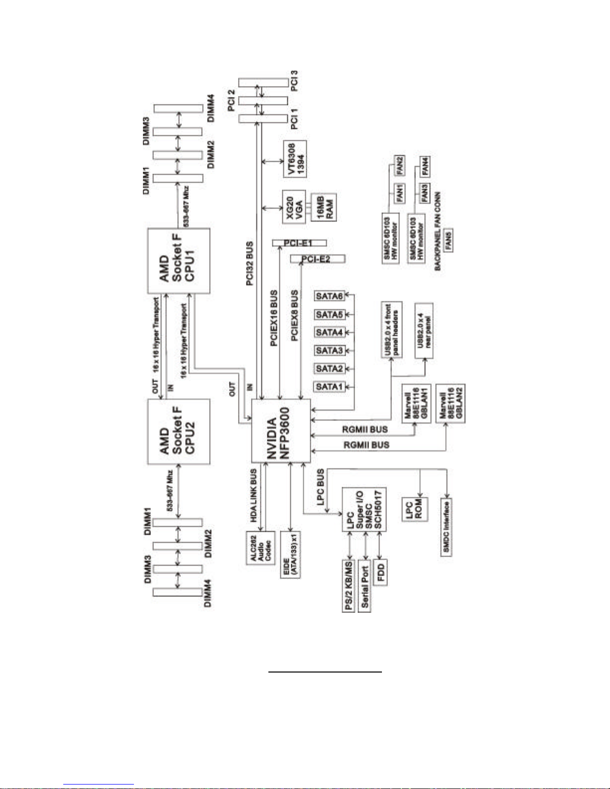
2.2 - Block Diagram
Thunder n3600B S2927 Block Diagram
http://www.tyan.com
10
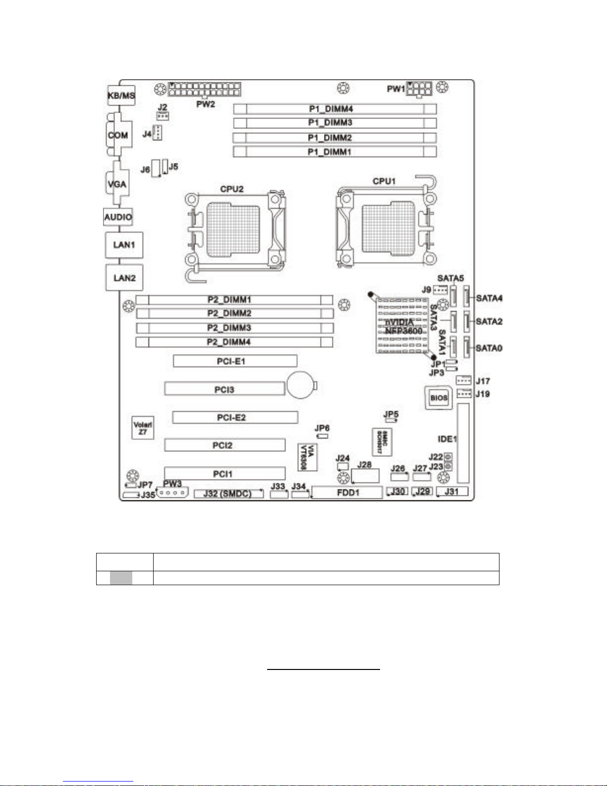
2.3 - Board Parts, Jumpers and Connectors
Jumper Legend
©©
OPEN - Jumper OFF, without jumper cover
©©
CLOSED – Jumper ON, with jumper cover
http://www.tyan.com
11
Jumper/Connector Function
J2 3-pin Fan Connector
J4/J9/J17/J19 4-pin Fan Connector with Speed Control
J5 CD_IN Pin Header
J6 Audio Pin Header
J26/J27 Front USB Connector
J28 COM Port Pin Header
J33/J34 IEEE1394 Connector
J35 IPMB Connector
J22 RESET Button
J23 POWER ON Button
JP6 1394 Disable Jumper
JP7 VGA Disable Jumper
JP1/JP3 ASF2.0/SMDC Select Jumper
JP5 Clear CMOS Jumper
J32 SMDC Connector
J31 Front Panel Header
J24/J29/J30 Reserved for OEM only

http://www.tyan.com
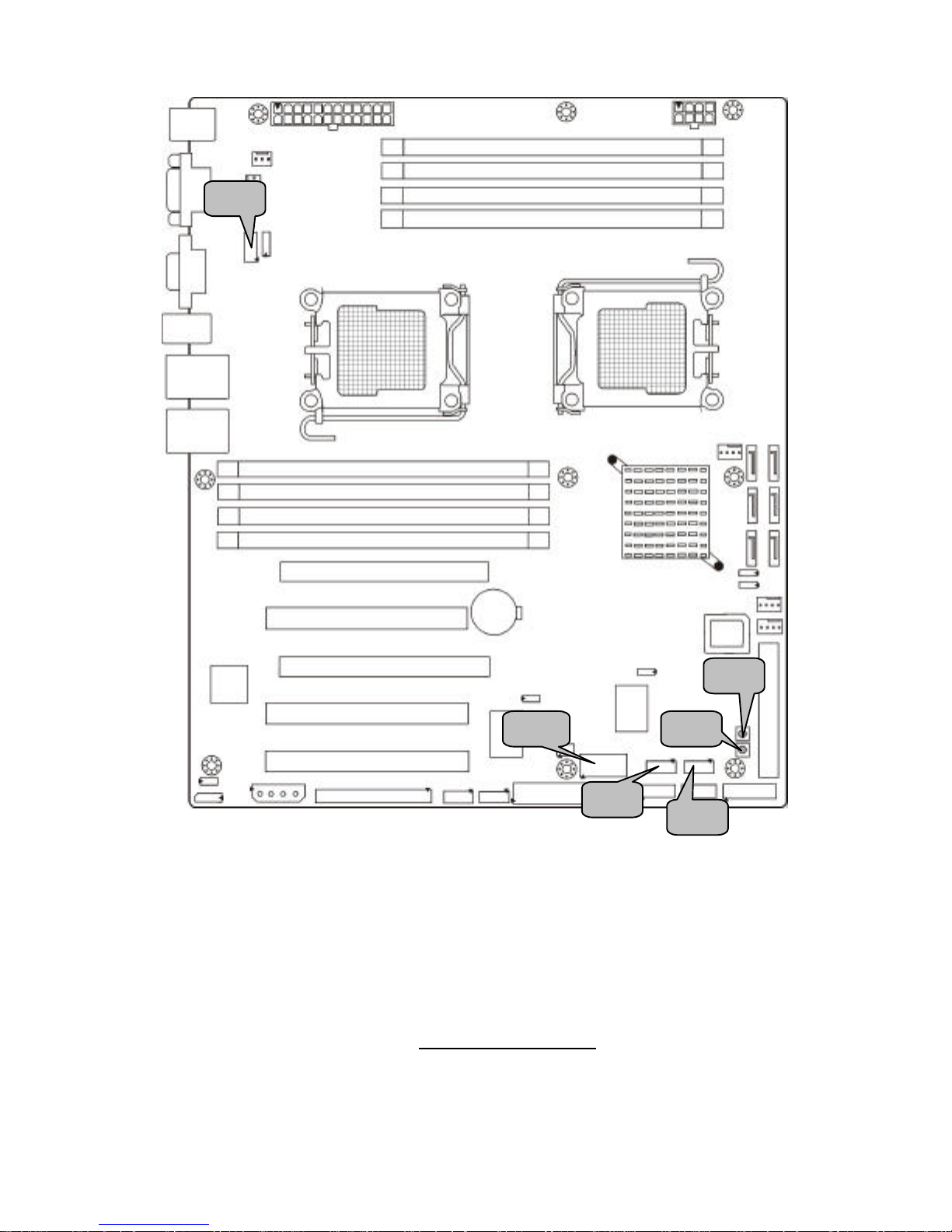
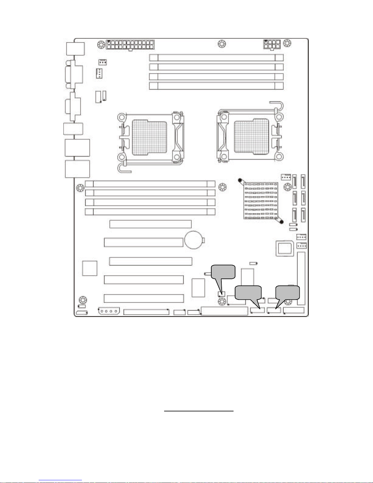
12
J35 J2 J4 J9 J19 J31 J17
http://www.tyan.com
13
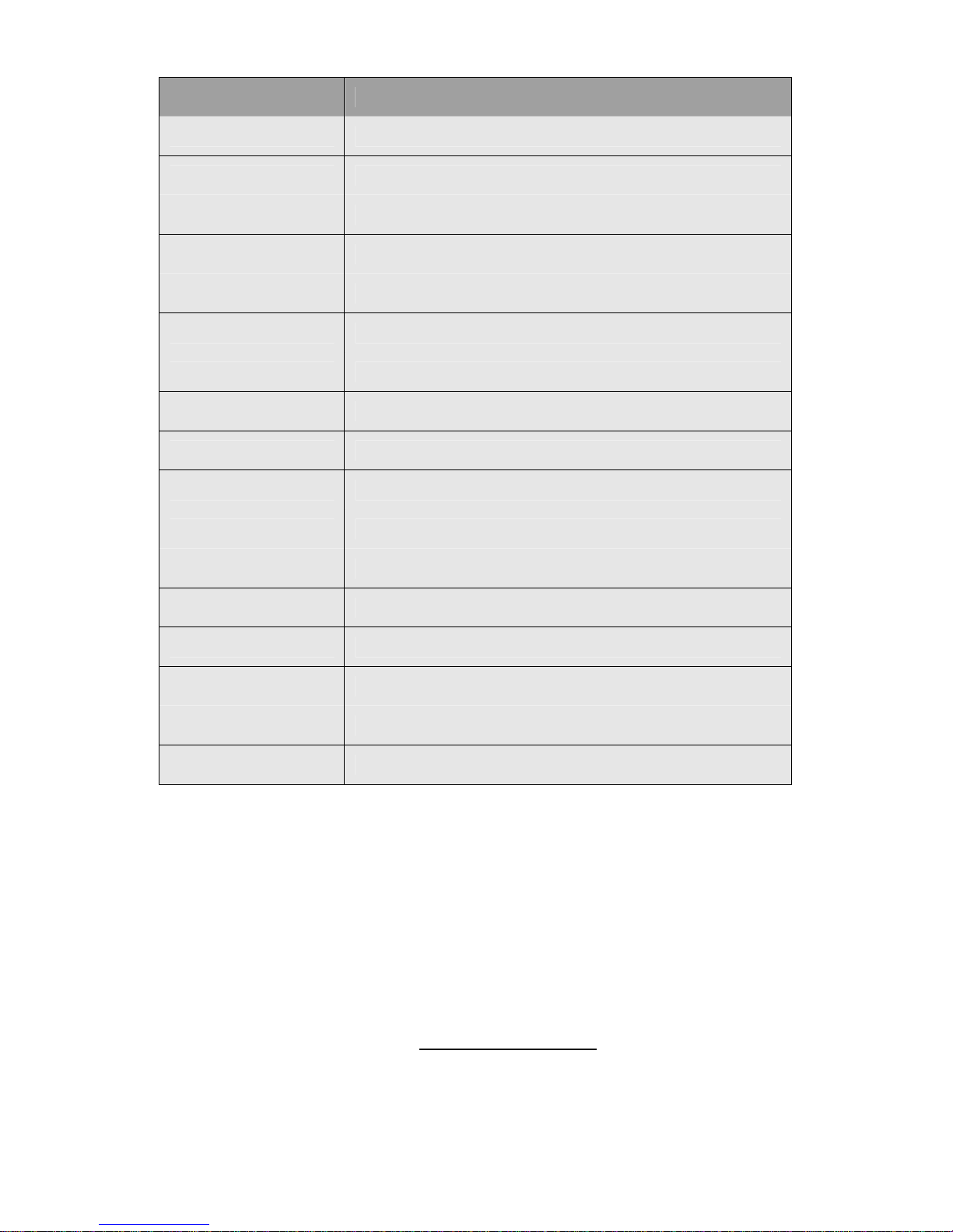
J2: 3-pin Fan Connector
1
Use this header to connect the chassis cooling fan to
your motherboard to keep the system stable and
reliable.
Pin 1 Pin 2 Pin 3
GND +12V NC
J4/J9/J17/J19: 4-pin FAN Connector with speed control
J9/J17/J19
1
J4
1
Use these headers to connect the cooling fans to your
motherboard to keep the system stable and reliable.
Pin 1 Pin 2 Pin 3 Pin 4
GND +12V Tachometer Speed Control
This connector supports the tachometer monitoring and
auto fan speed control.
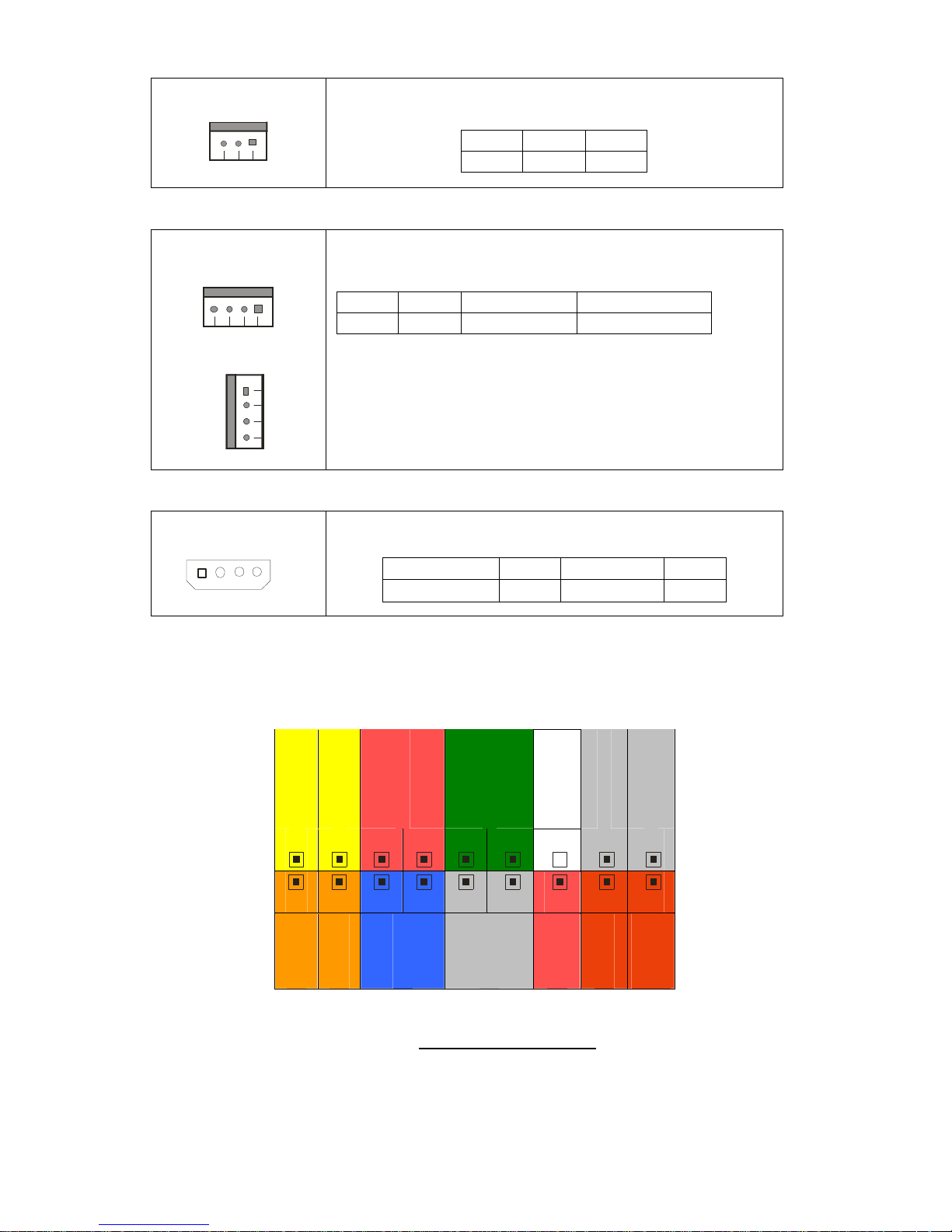
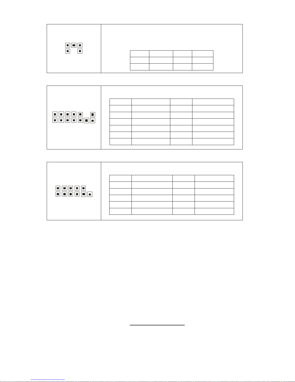
J35: IPMB Pin Header
1
Use this header to connect to the IPMB device.
Pin 1 Pin 2
Pin 3 Pin 4
IPMB DATA GND IPMB CLK NC
J31: Front Panel Header
The motherboard provides one front panel header for electrical connection to
the front panel switches and LED’s.
PWR LED+
PWR LED-
PWR SW#
Warning LED
KEY
GND
INTRUDER
2
4 6 8
10
12
14
16
18
1 3 5 7 9
11 13 15 17
HDD LED+
HDD LED-
Reset
NMI
+5VSB
SMBUS Data
SMBUS
Clock

http://www.tyan.com
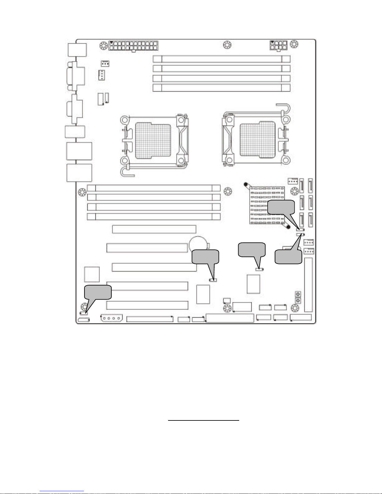
14
J34
J5 J32
J33

http://www.tyan.com
15
J33/J34: IEEE1394 Pin Header
10 2
9 1
J33: F1394-1
J34: F1394-2
Use these headers to connect to the external
devices of IEEE 1394.
Pin 1 XTPA 0/1 P Pin 2 XTPA 0/1 M
Pin 3 GND Pin 4 GND
Pin 5 XTPB0P Pin 6 XTPB0M
Pin 7 1394PWR 1/2 Pin 8 1394PWR 1/2
Pin 9 KEY Pin 10 GND
J5: CD_IN Pin Header
1
4
Use this header to connect to the external CD_IN
device.
Pin 1 Pin 2 Pin 3 Pin 4
CD-IN-L GND GND CD-IN-R
J32: SMDC Connector
The SMDC connector allows you to
connect with Tyan Server
Management Daughter Card
(SMDC). The S2927 supports Tyan
SMDC M3291. See Appendix for
more information on SMDC.
http://www.tyan.com
16
J26 J28 J27
J6
J22 J23
http://www.tyan.com
17
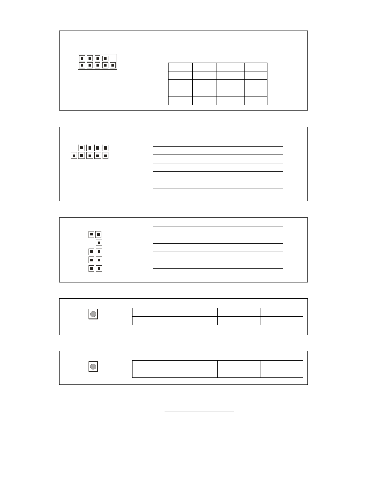
J28: COM Port Pin Header
1 9
2 10
Use these pin definitions to connect a port to COM2.
*TYAN does not provide cable for this header. It is
designed for OEM use only.
Pin 1 DCD Pin 2 DSR
Pin 3 RXD Pin 4 RTS
Pin 5 TXD Pin 6 CTS
Pin 7 DTR Pin 8 RI
Pin 9 GND Pin 10 KEU
J26/J27: Front Panel USB2.0 Connectors
10 2
9 1
J27: USB3
J26: USB4
Use these headers to connect to the USB devices
via the enclosed USB cable.
Pin 1 USBPWR Pin 2 USBPWR
Pin 3 USB 4/5- Pin 4 USB 6/7Pin 5 USB 4/5+ Pin 6 USB 6/7+
Pin 7 GND Pin 8 GND
Pin 9 KEY Pin 10 GND
J6: Audio Pin Header
1029
1
Pin 1 MIC-L-IN Pin 2 GND
Pin 3 MIC-R-IN Pin 4 NC
Pin 5 LINE-R-IN Pin 6 MIC-JD
Pin 7 I/O SENSE Pin 8 KEY
Pin 9 LINE-L-IN Pin 10 LINE-JD
J22: RESET Button
Pin 1 Pin 2 Pin 3 Pin 4
RSTSW- RSTSW- GND GND
J23: POWER ON Button
Pin 1 Pin 2 Pin 3 Pin 4
PWRSW-
PWRSW-
GND GND
http://www.tyan.com
18
J24
J29 J30
http://www.tyan.com
19
J24: LCM Connector (reserved for OEM only)
1 5
2 6
Use this header to connect the LCM module with
system monitoring function. This header is reserved for
barebone use.
Pin 1 VCC Pin 2 RXD2
Pin 3 KEY Pin 4 GND
Pin 5 +5VSB Pin 6 TXD2
J29: Fan Tachometer Pin Header (reserved for OEM only)
1 13
2 14
This header is reserved for barebone use.
Pin 1 FAN1_TACH Pin 2 FAN6_TACH
Pin 3 FAN2_TACH Pin 4 FAN7_TACH
Pin 5 FAN3_TACH Pin 6 FAN8_TACH
Pin 7 FAN4_TACH Pin 8 FAN9_TACH
Pin 9 FAN5_TACH Pin 10 FAN10_TACH
Pin 11 GND Pin 12 KEY
Pin 13 GND Pin 14 PWM1
J30: TYAN FP2 Pin Header (reserved for OEM only)
1 11
2 12
This header is reserved for barebone use.
Pin 1 LAN1 LED+ Pin 2 LAN1 LEDPin 3 LAN2 LED+ Pin 4 LAN2 LEDPin 5 NC Pin 6 GND
Pin 7 ID LED+ Pin 8 ID LEDPin 9 ID_LED S/W+ Pin 10 ID_LED S/WPin 11 NC Pin 12 KEY
http://www.tyan.com
20
JP5
JP6 JP1 JP7 JP3
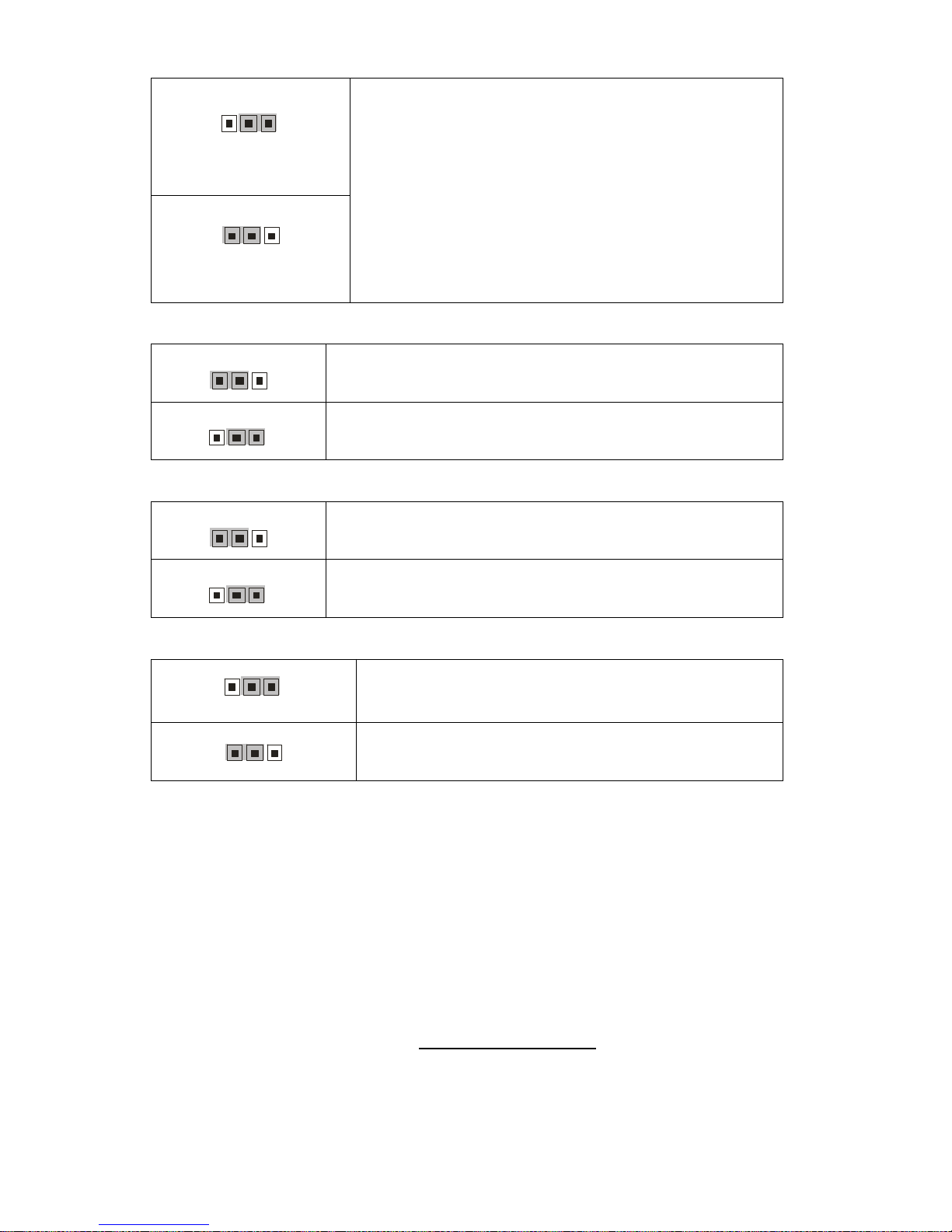
http://www.tyan.com
21
JP5: Clear CMOS Jumper
1
3
Normal
(Default)
3
1
Clear
Use this jumper when you forgot your system/setup
password or need to clear system BIOS setting.
How to clear the CMOS data
- Power off system and disconnect power
supply from AC source
- Use jumper cap to close Pin_2 and 3 for
several seconds to Clear CMOS
- Replace jumper cap to close Pin_1 and 2
Reconnect power supply to AC source
Power on system
JP7: VGA Enable/Disable Jumper
3
1
Enable the onboard VGA function. (Default)
1
3
Disable the onboard VGA function.
JP6: 1394 Enable/Disable Jumper
3
1
Enable the integrated 1394a function of VT6308 PCI
FireWire controller. (Default)
1
3
Disable the integrated 1394a function of VT6308 PCI
FireWire controller.
JP1/JP3: SMDC/ASF2.0 Select Header
1
3
Support ASF2.0 (Default)
3
1
Support SMDC card
http://www.tyan.com
22
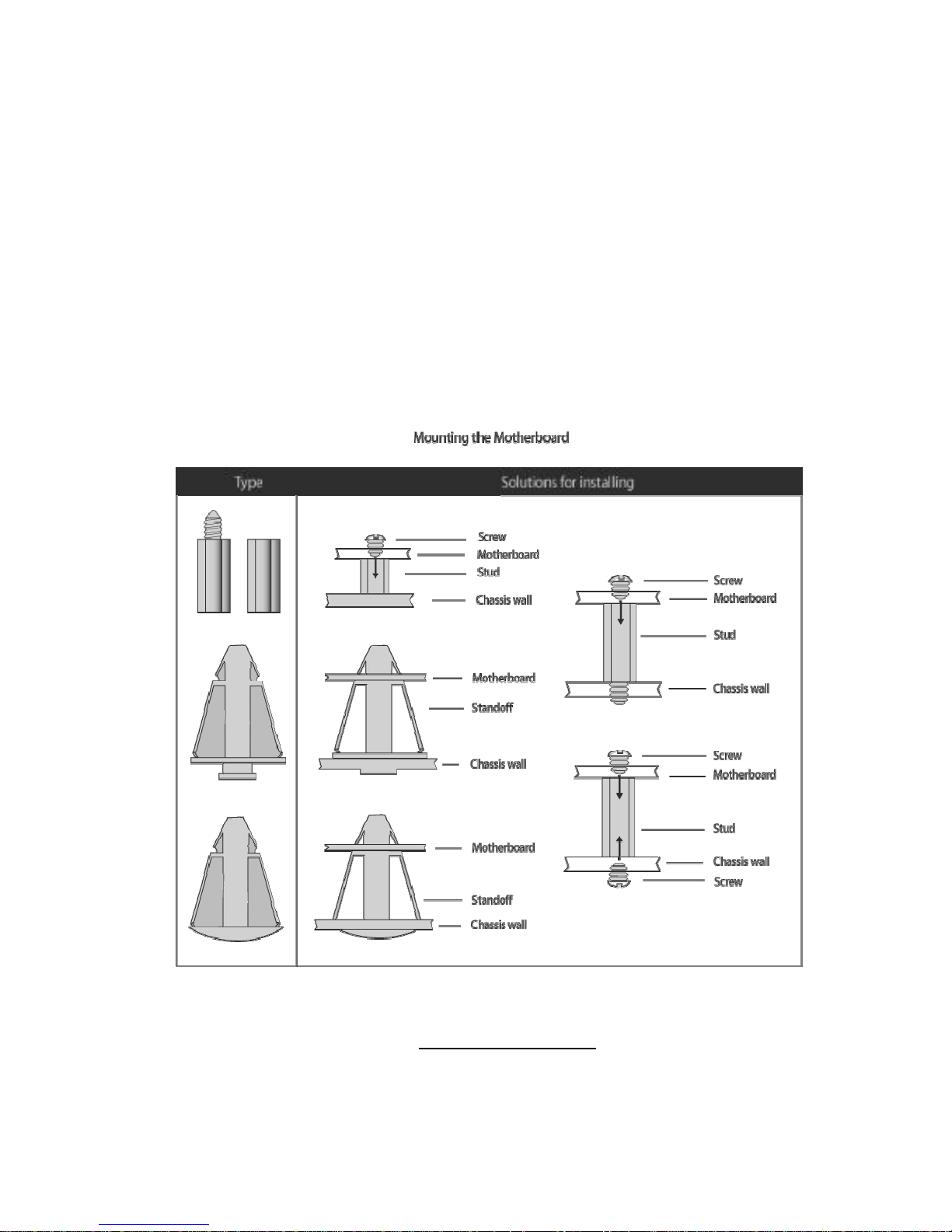
2.4 - Tips on Installing Motherboard in Chassis
Before installing your motherboard, make sure your chassis has the
necessary motherboard support studs installed. These studs are usually
metal and are gold in color. Usually, the chassis manufacturer will pre-install
the support studs. If you are unsure of stud placement, simply lay the
motherboard inside the chassis and align the screw holes of the
motherboard to the studs inside the case. If there are any studs missing,
you will know right away since the motherboard will not be able to be
securely installed.
Some chassis’ include plastic studs instead of metal. Although the plastic
studs are usable, TYAN recommends using metal studs with screws that will
fasten the motherboard more securely in place.
Below is a chart detailing what the most common motherboard studs look
like and how they should be installed.
http://www.tyan.com
23
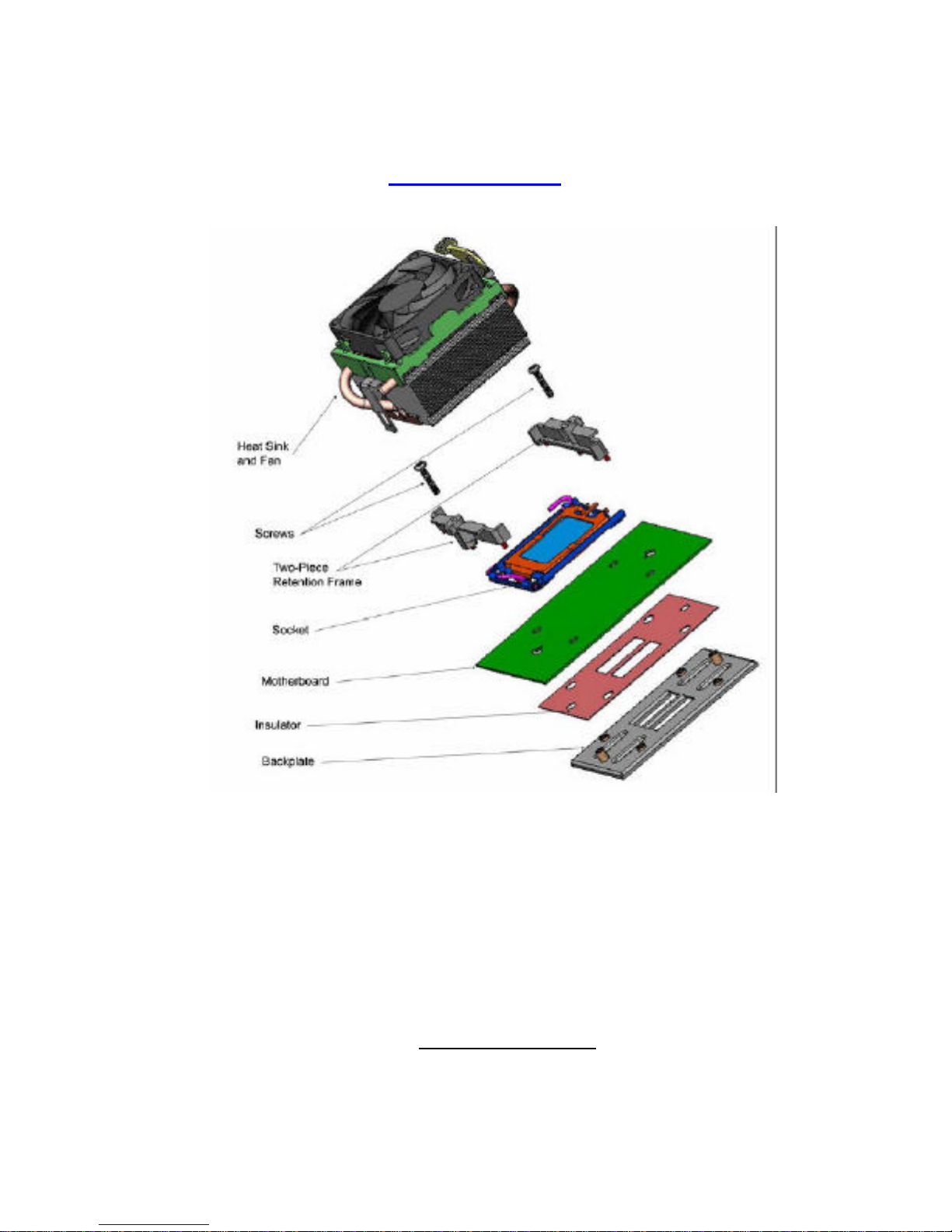
2.5 - Installing the Processor(s)
Your S2927 ports the latest processor technologies from AMD. Check the
TYAN website for latest processor support:
http://www.tyan.com
Figure 1. Exploded View of Thermal Solution AMD PIB Platforms based on AMD
Socket F Processor
http://www.tyan.com
24
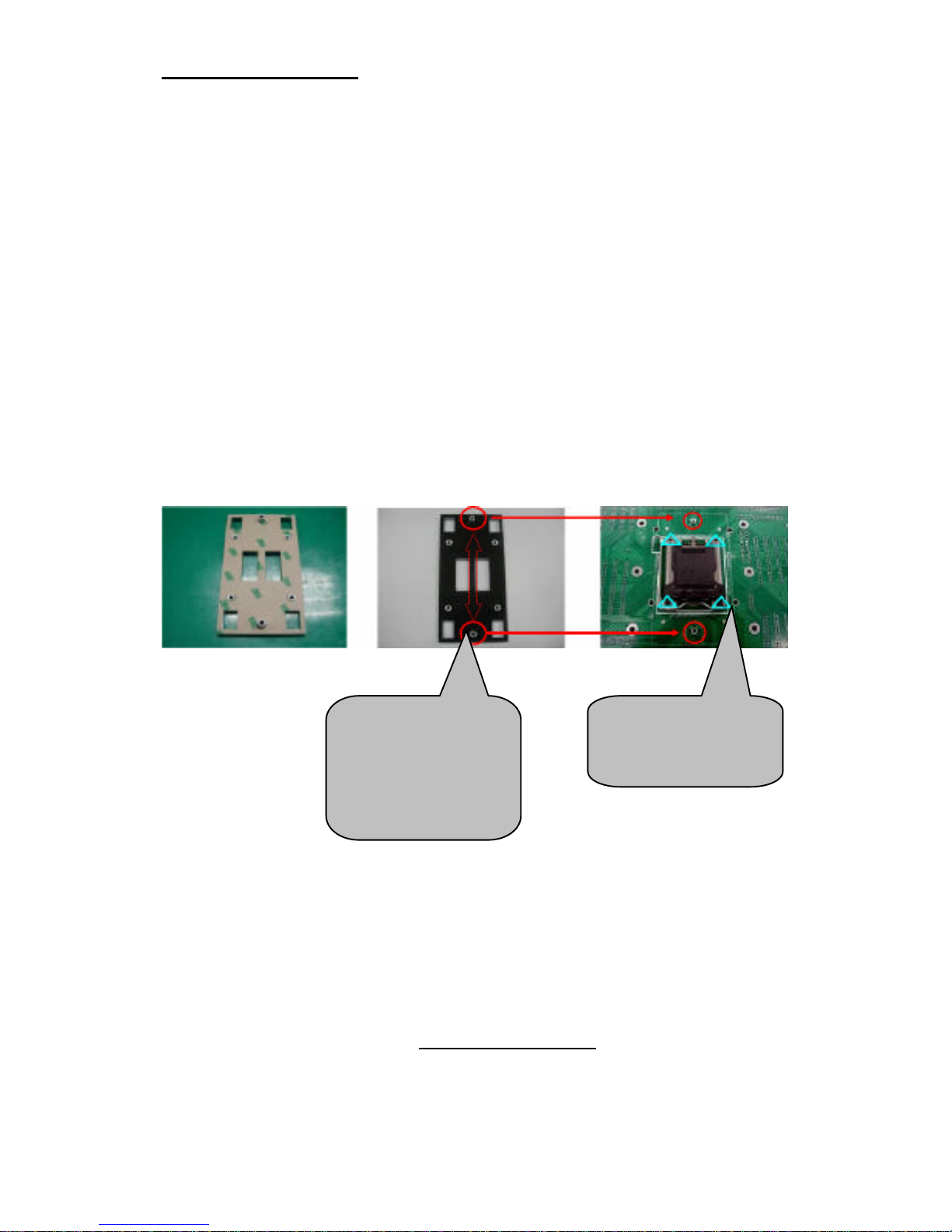
Back plate Assembly
The back plate is mounted on the backside of the motherboard and enhances
local stiffness to support shock and vibration loads acting on the heat sink. The
back plate assembly prevents excessive motherboard warpage in the area near
the processor. Without a back plate, excessive warpage could cause serious
damage to electrical connections of the processor socket and integrated circuit
packages surrounding the processor. The back plate also serves as a stiffener
plate for the LGA socket.
While doing the installation, be careful in holding the components. Follow these
instructions to install your back plate:
1. Remove the release liner from the back plate.
2. Align the PEM nuts on the back plate to the holes on the reverse side
of the PCB.
3. First, insert the taller upper & lower middle PEM nuts through the
holes of the PCB. The remaining four shorter PEM nuts should
automatically fit the 4 holes on the PCB as shown in the following
pictures.
Let 2 upper &
lower-middle
PEM nuts pass
through the
holes.
4 PEM nuts
should fit 4
holes.
http://www.tyan.com
25
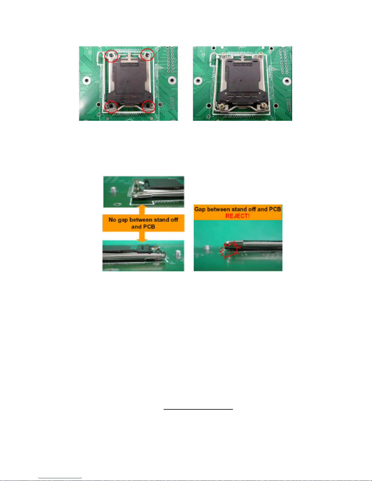
4. Locate four screw holes on socket and screw the socket to the PCB
board.
NOTE: Do not assemble CPU before securing socket with screws.
5. Inspect Socket F assembly to PCB. The Socket F must be tightly
attached onto the PCB. There must NOT be any gap between stand
off the PCB.
http://www.tyan.com
26
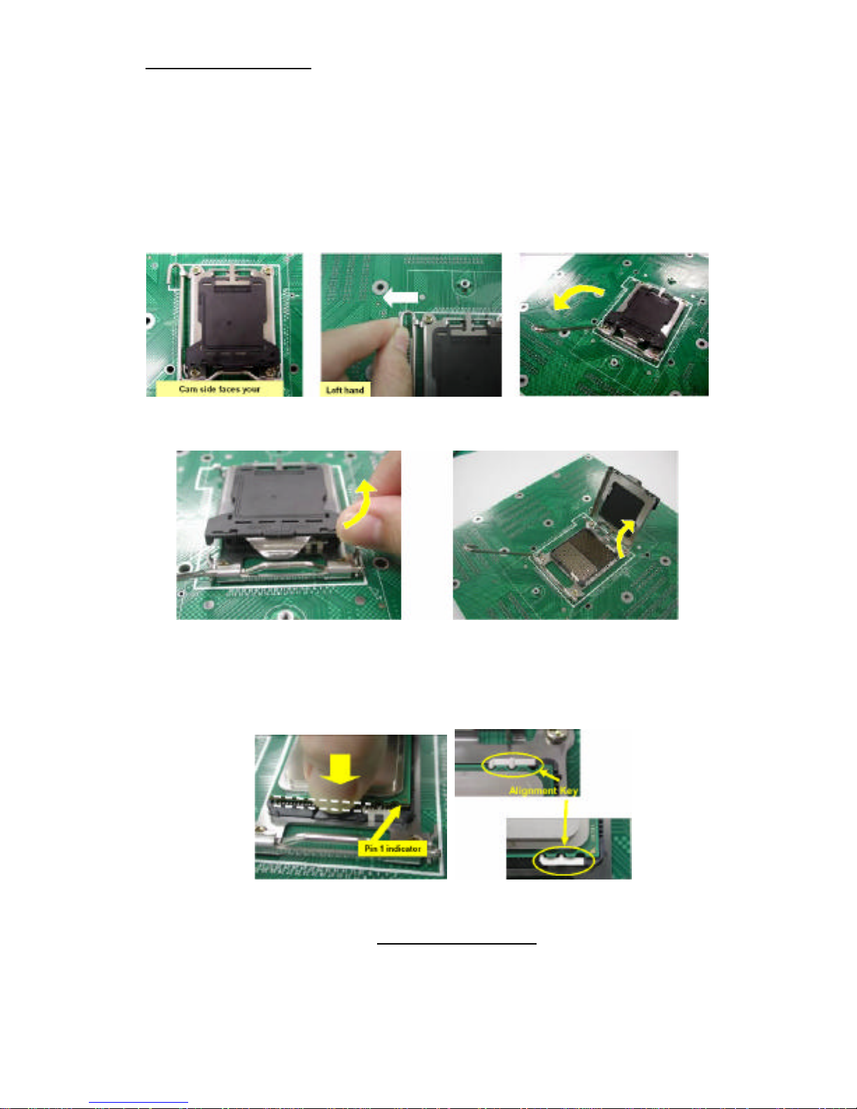
Processor Installation
The processor should be installed carefully. Make sure you are wearing an
antistatic strap and handle the processor as little as possible.
Follow these instructions to install your processor:
1. Place the PCB such that the socket cam side faces you. Make sure
the lever hook is on your top-left side.
2. Use your left thumb and forefinger to hold the lever hook, then pull it
to the left side to clear the retention tab.
3. Rotate the lever to a fully open position.
4. Lift the load plate to a fully open position.
5. Locate the Pin 1 indicator of the package. Align the package with the
socket and carefully insert the package into the socket with vertical
motion only. Vertically check if the CPU is seated well in the socket
housing. If not, take out the CPU, with vertical motion only, and
repeat the above steps.
NOTE: The alignment keys must be located in the notches of the package.
http://www.tyan.com
27
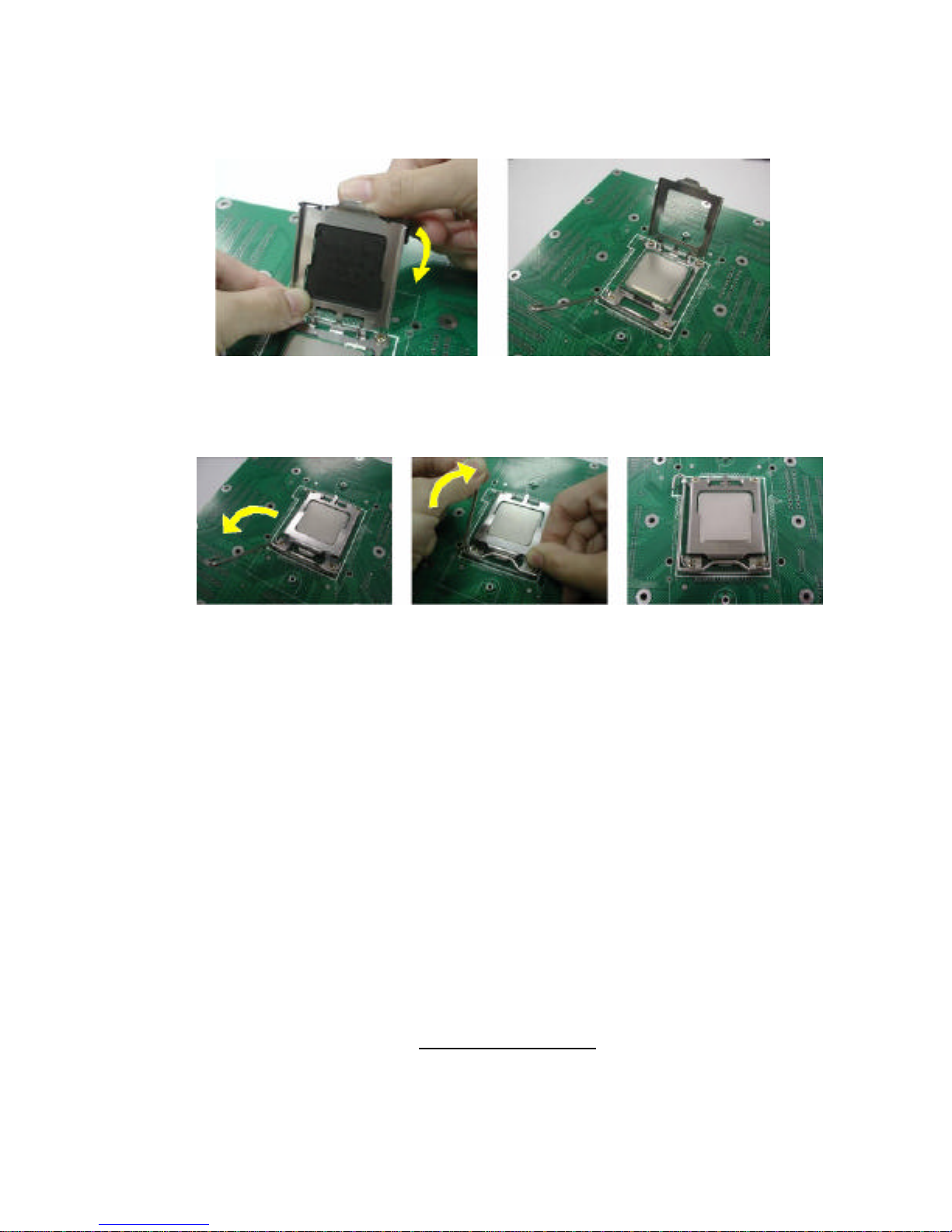
6. Remove the PnP cap. Use your left hand to hold the load plate.
Then use your right thumb to remove the PnP cap from the load plate.
With the package in the socket, the PnP cap removal process will not
damage the contacts.
7. Close the socket. Rotate the load plate onto the package lid.
Engage the load lever while pressing down lightly onto the load plate.
Secure the lever near the hook end under the retention tab.
8. Repeat this procedure for the second processor if necessary.
 Loading...