

TYAN Tomcat n3400B S2925, S2925, S2925G2NR, S2925A2NRF User Manual

1
Tomcat n3400B
///
S2925
Version 1.0
Copyright
Copyright © TYAN Computer Corporation, 2006. All rights reserved. No part of
this manual may be reproduced or translated without prior written consent from
TYAN Computer Corp.
Trademark
All regist ered and unregistered trademarks and company names contained in
this manual are property of their respective owners including, but not limited to
the following.
TYAN, Tomcat n3400B are trademarks of TYAN Computer Corporation.
AMD, Opteron, and combination s thereof are trademarks of AMD Corporation.
AMI, AMI BIOS are trademarks of AMI Technologies.
Microsoft, Windows are trademarks of Microsoft Corporation.
SuSE,is a trademark of SuSE AG.
Marvell® is a trademark of Broadcom Corporation and/or its subsidiaries
XGI and XG20 are trademarks of XGI Corporation
nVIDIA, nForce are trademarks of NVIDIA Corporation.
Notice
Information contained in this document is furnished by TYAN Computer
Corporation and has been reviewed for accuracy and reliability prior to printing.
TYAN assumes no liability whatsoever, and disclaims any express or implied
warranty, relating to sale and/or use of TYAN products including liability or
warranties relating to fitness for a particular purpose or merchantability. TYAN
retains the rig ht to make changes to product descriptions and/or specifications
at any time, without notice. In no event will TYAN be held liable for any direct or
indirect, incidental or consequential damage, loss of use, loss of data or other
malady resulting from errors or inaccuracies of information contained in this
document.

2
Table of Contents
Check the box contents! Page 4
Chapter 1: Introduction
1.1 Congratulations Page 5
1.2 Hardware Specifications Page 5
Chapter 2: Board Installation
2.1 Board Image Page 8
2.2 Block Diagram Page 9
2.3 Board Parts, Jumper s and Connectors Page 10
2.4 Installing the Processor Page 22
2.5 Heatsink Retention Frame Installation Page 23
2.6 Thermal Interface Material Page 24
2.7 Heatsink Installation Procedure s Page 25
2.8 Finishing Installing Heatsink Page 26
2.9 Tips on Installing Motherboard in Chassis Page 27
2.10 Installing the Memory Page 28
2.11 Attaching Drive Cables Page 30
2.12 Installing Add-In Cards Page 32
2.13 Connecting External Devices Page 33
2.14 Installing the Power Supply Page 34
2.15 Finishing Up Page 34
Chapter 3: BIOS Setup
3.1 About the BIOS Page 35
3.2 BIOS Menu Bar Page 35
3.3 Setup Basics Page 36
3.4 Getting Help Page 36
3.5 In Case of Problems Page 36
3.6 BIOS Main Menu Page 37
3.7 Advanced Menu Page 38
3.8 PCI PnP Menu Page 60
3.9 Boot Menu Page 62
3.10 Security Menu Page 65
3.11 Chipset Menu Page 66
3.12 Exit Menu Page 73
Chapter 4: Diagnostics
4.1 Beep Codes Page 75
4.2 Flash Utility Page 75
Appendix I: SMDC Information
Appendix II: How to Make a Drive Diskette
Page 78
Page 80
Glossary Page 82
Technical Support Page 88
3
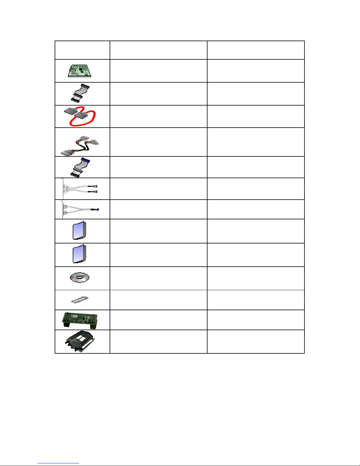
Check the box contents!
Item S2925G2NR S2925A2NRF
1x Tomcat n3400B
S2925G2NR motherboard
1x Tomcat n3400B
S2925A2NRF motherboard
1x 34-Pin floppy drive cable
1x 34-Pin floppy drive cable
6 x SATA cable 6 x SATA cable
3 x SATA Drive Power Adapter
3 x SATA Drive Power
Adapter
1 x Ultra-DMA-100/66 IDE
cable
1 x Ultra-DMA-100/66 IDE
cable
---- 1 x IEEE1394a Cable
1 x USB2.0 cable 1 x USB2.0 cable
1 x Tomcat n3400B user’s
manual
1 x Tomcat n3400B user’s
manual
1 x Tomcat n3400B Quick
Reference guide
1 x Tomcat n3400B Quick
Reference guide
1 x TYAN driver CD 1 x TYAN driver CD
1 x I/O shield 1 x I/O shield
1 x SLI bridge 1 x SLI bridge
1x Retention Module 1 x Retention Module

4

5
Chapter 1: Introduction
1.1 - Congratulations
You have purchased one of the most powerful server solutions. The Tomcat
n3400B (S2925) is a flexible AM D64 platform for multiple applications, based on
NVIDIA nForce Pro3400 and SMSC DME5017 chipsets.
Designed to support AMD® Opteron™ 1000 series processors and 8GB DDRII667 memory , the S2925 with integrated Dual Gigabit Ethernet LAN, built-in
16MB XGI XG20TM video and six serial ATA ports, is ideal for CPU, memory,
and video intensive applications such as CAD, Graphics Design, and High
Bandwidth Video Editing, etc.
Remember to visit TYAN’s Website at http://www.TYAN.com. There you can
find information on all of TYAN’s products with FAQs, online manuals and BIOS
upgrades.
1.2 - Hardware Specifications
Processor
•uPGA 940-pin AM2 socket
•AMD Opteron 1000 series
processor
Expansion Slots
•One (1) x16 PCI -E connector for
graphics
•One (1) x16 PCI -E with x8
bandwisth
•One (1) PCI Express connector
•Three 32-bit, 33MHz PCI v2.3
slots
•Total six usable expansion slots
Chipset
•nVIDIA nForce Pro 3400
•SMSC DME5017
System Management
•SMSC DME5017 w/ hardware
monitoring
•Six 4-pin fan header
•Temperature and voltage
monitoring
•Watchdog timer
Integrated 2D/3D PCI Graphics
•XGI XG20 PCI graphics controller
•16MB Frame Buffer of video
memory
Integrated LAN Controllers
•Two nForce Pro 3400 integrated
MAC with Marvell 88E1116-CAA
Gigabit Ethernet PHY
- 32-bit PCIv2.3interface
- IEEE802.3 compliant, WOL/PXE
support
- Pin header for front panel LAN
LED
Integrated Audio
•Realtek ALC262 audio CODEC
•HAD 2.0 specification compliant
•2x5 pin header for front panel
audio connector
•CD-in connector
Integrated PCI 1394
•Co-lauout VIA VT6307 and
VT6308 PCI FireWire
(IEEE1394) controller

6
Memory
•Dual memory channels
•Supports up to four DDR-800
DIMMs
•Up to 8GB of unbuffered,
ECC/non-ECC memory
Integrated PCI IDE
•One (1) ATA IDE slot for two IDE
devices
•Support for ATA-133/100/66/33
IDE drives and ATAPI compliant
devices
Integrated Serial ATA II
•Serial ATA Host controllers
embedded
•Supports six serial ports run ning at
3.0Gb/s
•NV RAID 0, 1, 0+1, 5 and JBOD
support
•SATA activity LED connector
Integrated I/O Interface
•One (1) floppy connector
•Four (4) USB 2.0 ports (via cable)
•One (1) COM port (via cable)
•Tyan 2x9 front panel pin header
•2x25 pin SMDC pin header
•One (1) ID LED pin header
•One (1) parallel pin header
•One TYFP2 pin header
•Two IEEE1394 ports (via cable)
Back Panel I/O Ports
•Stacked PS/2 mouse & keyboard
ports
•One (1) COM1 connector
•One (1) 15-pin VGA port
•3 audio jacks (from bottom: line
out, line in, MIC)
•Stacked two USB 2.0 ports and
one RJ45 (Marvell 88E1116-CAA
PHy + nVIDIA MAC) 10/100/1000
Base-T port with link/activity LED
•Stacked two USB 2.0 ports and
one RJ45 (Marvell 88E1116-CAA
PHy + nVIDIA MAC) 10/100/1000
Base-T port with link/activity LED
BIOS
•AMI BIOS 8Mbit Flash
•Supports ACPI 1.0
•PnP, DMI2.0, WfM 2.0 power
management
Power
•ATX 12V support, on board 4phase VRD
•Universal 24-pin + 8-pin power
connectors
•4-pin auxiliary power connector
Form Factor
•ATX footprint, 9.6” x 12.0”
(244mmx305mm)
Regulatory
•FCC Class B (Declaration of
Conformity)
•CE (Declaration of Conformity)
7
Chapter 2: Board Installation
You are now ready to install your motherboard. The mounting hol e pattern of
the Tomcat n3400B S2925 matches the ATX specification. Before continuing
with installation, confirm that y our chassis supports an ATX motherboard.
How to install our products right… the first time
The first thing you should do is read ing this user’s manual. It contains important
information that will make configuration and setup much easier. Here are some
precautions you should take when installing your motherboard:
(1) Ground yourself properly before removing your motherboard from the
antistatic bag. Unplug the power from your computer power supply and
then touch a safely grounded object to release static charge (i.e. power
supply case). For the safest conditions, TYAN recommends wearing a
static safety wrist strap.
(2) Hold the motherboard by its edges and do not touch the bottom of the
board, or flex the board in any way.
(3) Avoid touching the motherboard components, IC chips, connectors,
memory modules, and leads.
(4) Place the motherboard on a grounded antistatic surface or on the
antistatic bag that the board was shipped in.
(5) Inspect the board for damage.
The following pages include details on how to install your motherboard into your
chassis, as well as installing the processor, memory, disk drives and cables.
NOTE
DO NOT APPLY POWER TO THE BOARD IF IT HAS BEEN
DAMAGED
8
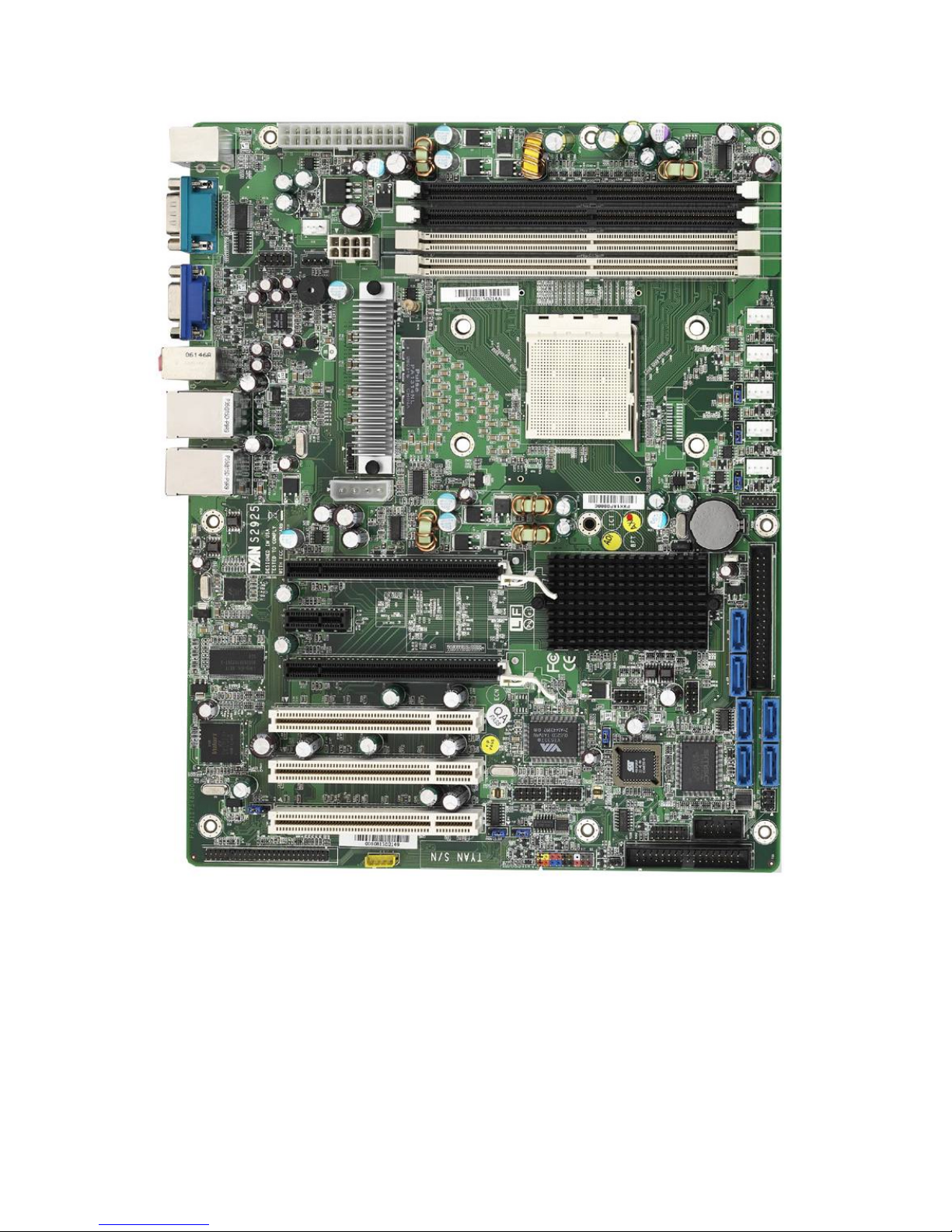
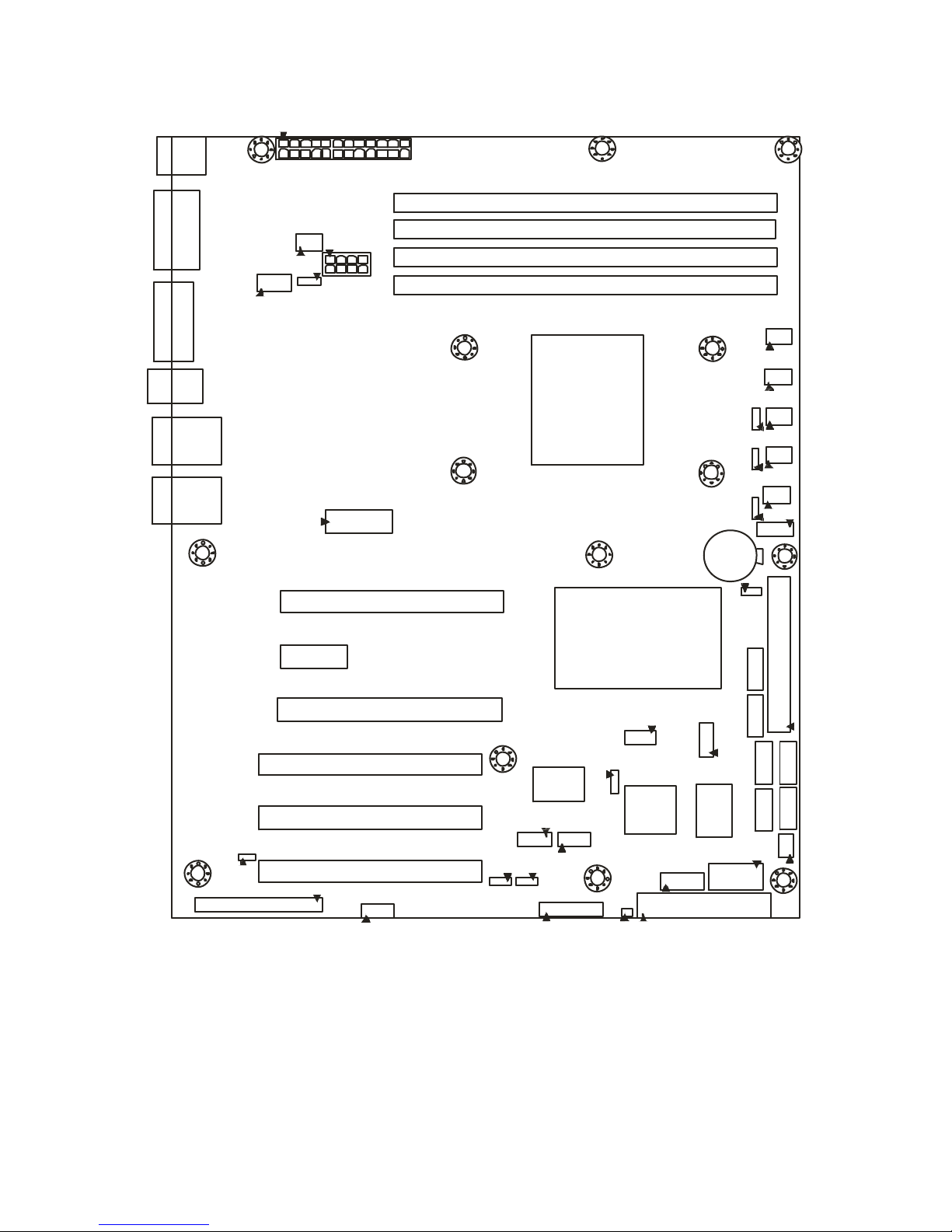
2.1- Board Image
This picture is representative of the latest board revision available at
the time of publishing. The board you receive may or may not look
exactly like the above picture.
9
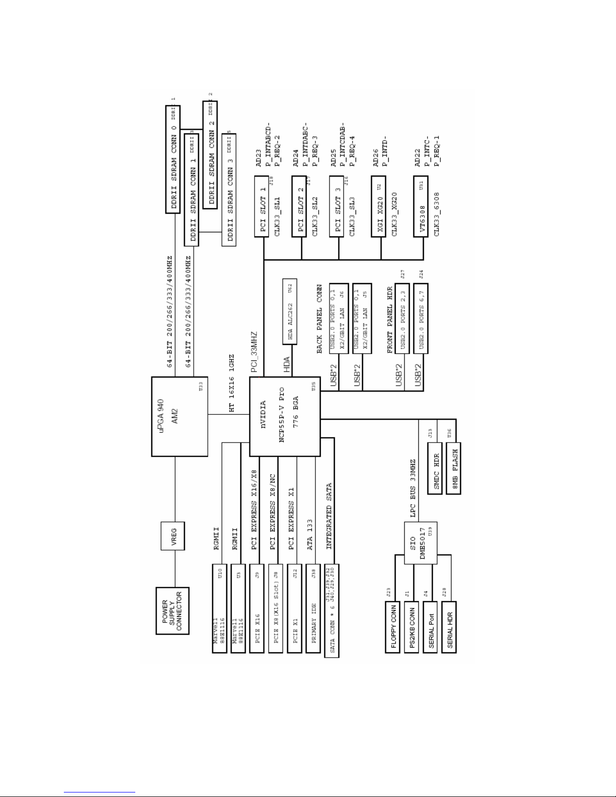
2.2 - Block Diagram
Tomcat n3400B S2925 Block Diagram
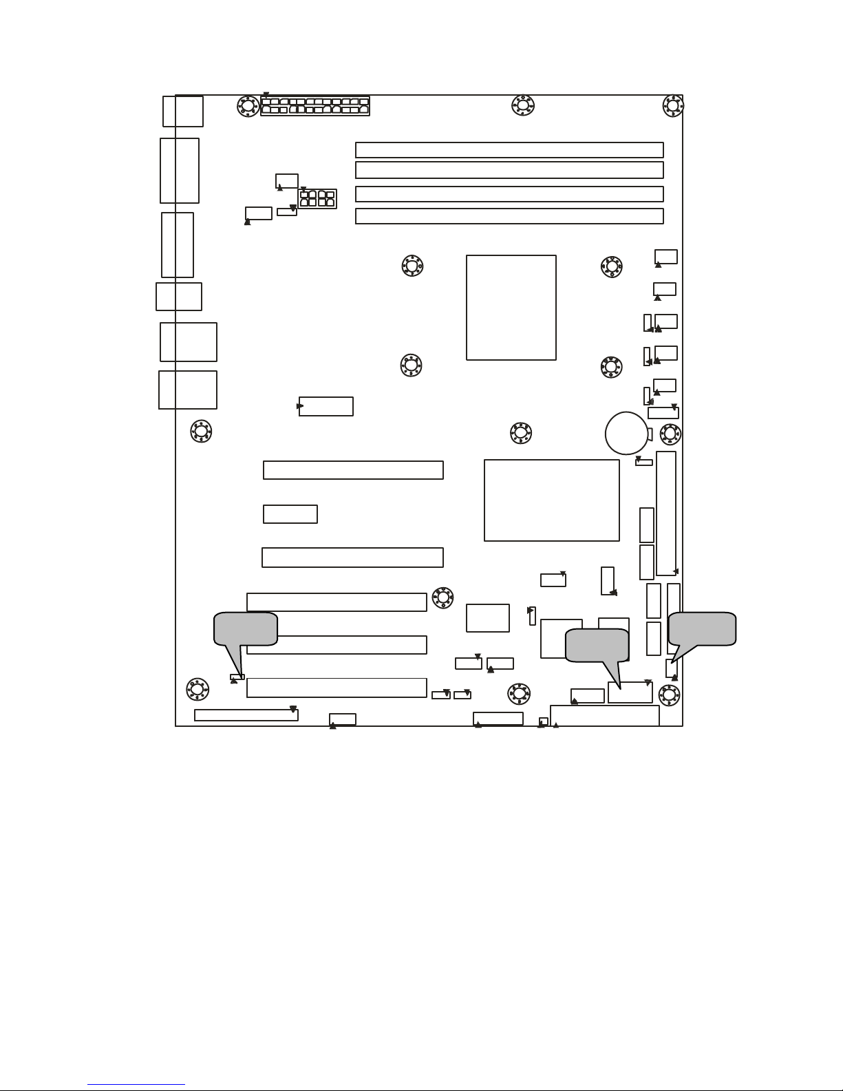
10
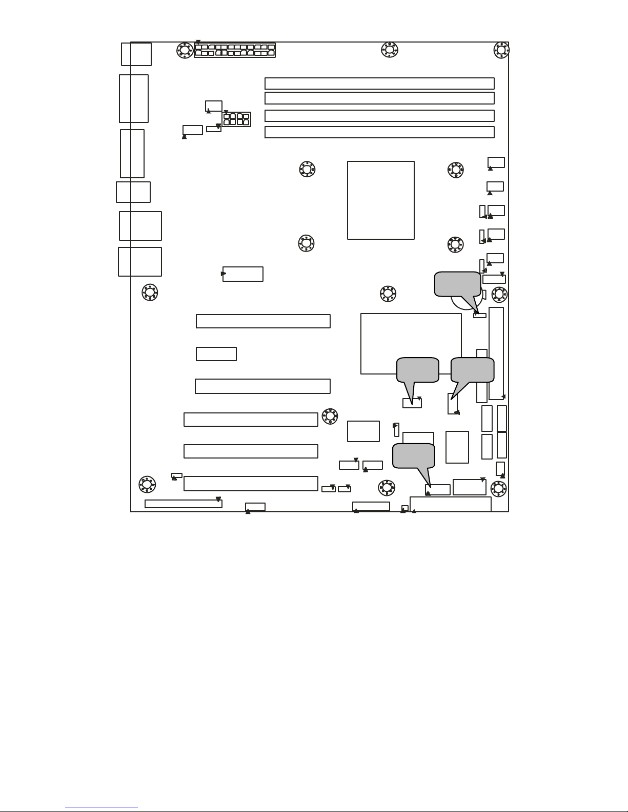
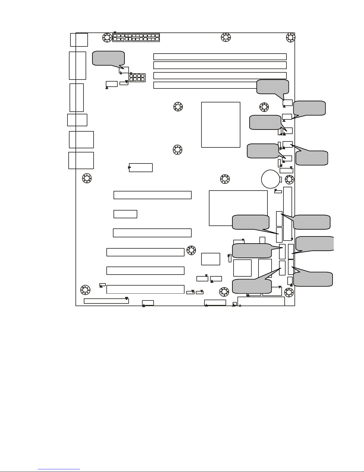
2.3 - Board Parts, Jumpers and Connectors
DIMM4
DIMM3
DIMM2
DIMM1
PW1
KB/MS
COM1
VGA
AUDIO
LAN1
USB1
LAN2
USB2
FAN5
PW2
PW3
PCI-E1
PCI-E3
PCI-E2
PCI 1
PCI-E3
PCI 2
PCI 3
J13
J15
J19
J22
J23
J25
J28
BIOS
SMSC
DME5017
J25
VT6308
VIA
J20
J21
JP2 JP3
SATA1
SATA0
SATA2
SATA3
SATA4 SATA5
IDE
J27
J24
JP5
J41
J33
J34
J35
J36
J37
JP6
JP7
JP8
CPU
nVIDIA
nForce Pro3400
JP1 JP9
JP4
J11
J7
VBAT
11
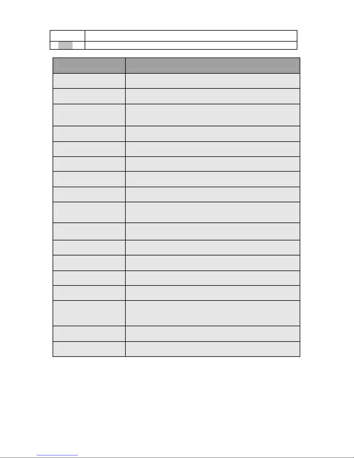
Jumper Legend
©©
OPEN - Jumper OFF, without jumper cover
©©
CLOSED – Jumper ON, with jumper cover
Jumper/Connector Function
JP2/JP3 SMDC/ASF 1.0 Select Header
J19 Front Panel Header
J20/J21
Front Panel IEEE 1394 Headers
J20: 1394-1, J21: 1394-2
J15 IPMB Pin Header
J13 SMDC Connector
JP9 LCM Module Connector
JP1 Enable/Disable VGA Function Jumper
J28 COM2 Header
J24/J27
Front Panel USB2.0 Connectors
J24: USB3, J27: USB4
J25 Front Panel LAN1/LAN2/ID LED Headers
JP5 Clear CMOS Jumper
JP4 Enable VT6308 (1394) Function Jumper
J7 Front Audio Header
J11 External CD-in Header
J34/J35/J36/J37/J10
Front Fan Connector s
J34: FAN1, J35: FAN2, J36: FAN3, J37: FAN4
J33 CPU Fan Connector
SATA 0/1/2/3/4/5 Serial ATA RAID Connectors

12
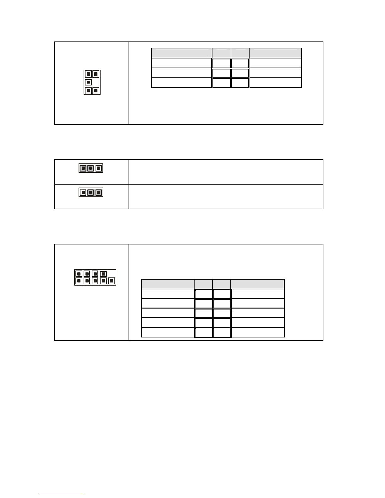
JP2/JP3: SMDC/ASF1.0 Select Header
1
3
(Default)
Support SMDC card
(JP2 & JP3 )
3
1
Support ASF 1.0
(JP2 & JP3)
JP3
Pin 1 Pin 2 Pin 3
SMB_CLK LAN_BMBCLK ASFCLK
JP2
Pin 1 Pin 2 Pin 3
SMB_DATA LAN_SMBDA ASFDA
J19 J21 JP2
J15
J13 J20
JP3
13
J19: Front Panel Header
The Front Panel Header is used to connect some control or signal wires from
motherboard to chassis, such as HDD LED, power LED, power button, and
reset button.
J20/J21: Front Panel IEEE1394 Headers
1 9
2 10
Signal Pin Pin
Signal
XTPA+ 1 2 XTPA-
GND 3 4 GND
XTPB+ 5 6 XTPB-
POWR 7 8 POWR
_ 9 10
GND
Use these headers to connect to the external
devices of IEEE 1394.
J20: 1394-1, J21: 1394-2
J15: IPMB Pin Header
1
Use this header to connect to the IPMB device.
Pin 1 Pin 2 Pin 3 Pin 4
IPMB
DATA
GND IPMB
CLK
NC
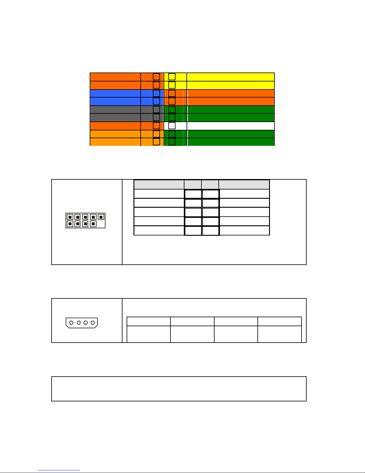
J13: SMDC Connector
The SMDC connector allows you to connect with Tyan Server Management
Daughter Card (SMDC). The S2925 supports Tyan SMDC M3291. See
Appendix for more information on SMDC.
HDDLED+
1¾ ¾2 PWR LED+
HDDLED- 3¾ ¾ 4 PWR LED-
Reset Switch 5¾ ¾ 6 PWR Switch
Reset Switch 7¾ ¾ 8 Power Switch
NMI 9¾ ¾
10
WLED+
NMI 11¾ ¾ 12 WLED-
5VSB 13¾ ¾ 14 key
SMBus Data 15¾ ¾ 16 GND
SMBus Clock 17¾ ¾ 18 NC
14
JP1
JP9
J28
15
JP9: LCM Module Connector
5
1
10
2
Use this header to connect the LCM module with
system monitoring function. This header is reserved for
barebone use.
Signal Pin Pin Signal
VCC
1 2
RXD2
_ 3 4
GND
5VSB
5 6
TXD2
JP1: Enable/Disable VGA Function Jumper
3
1
Enable the onboard VGA function. (Default)
3
1
Disable the onboard VGA function.
J28: COM2 Header
1 9
2 10
Use these pin definitions to connect a port to COM2.
*TYAN does not provide cable for this header. It is
designed for OEM use only.
Signal Pin Pin
Signal
DCD 1 2 DSR
RXD 3 4 RTS
TXD 5 6 CTS
DTR 7 8 RI
GND 9 10
Key
16
J24 J25 J27 JP5
17
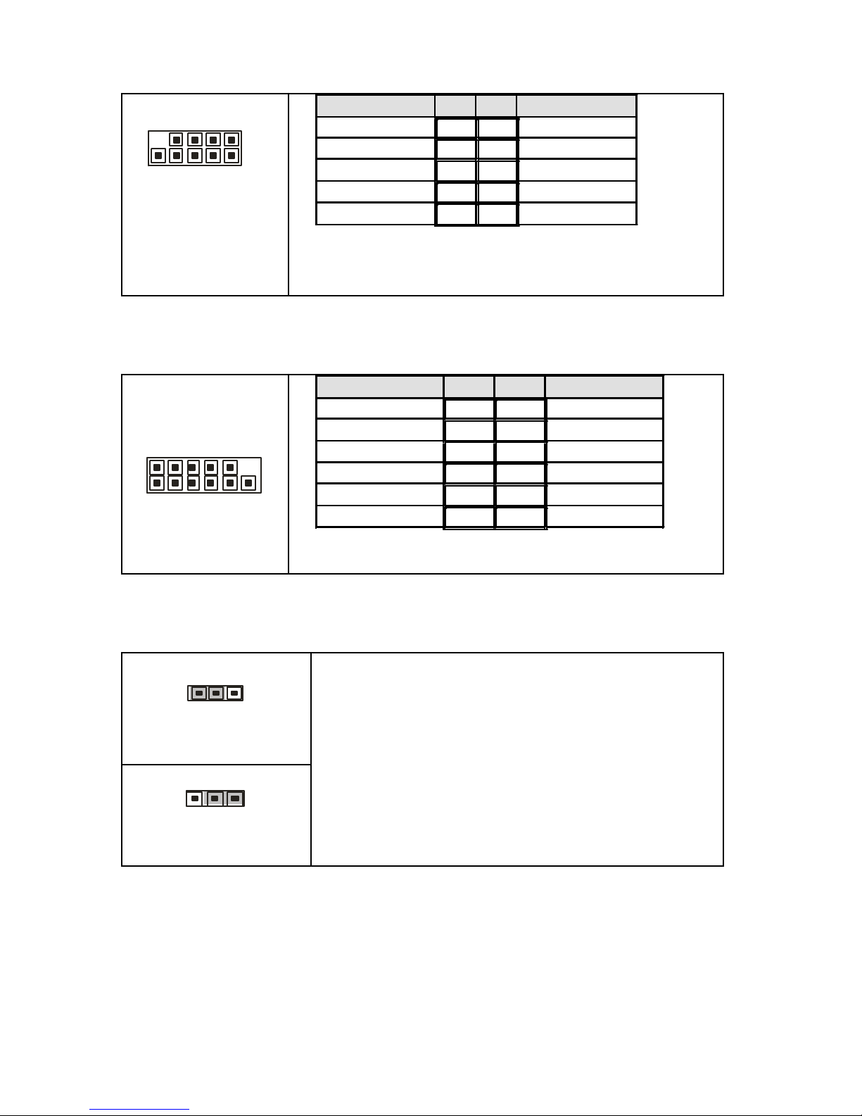
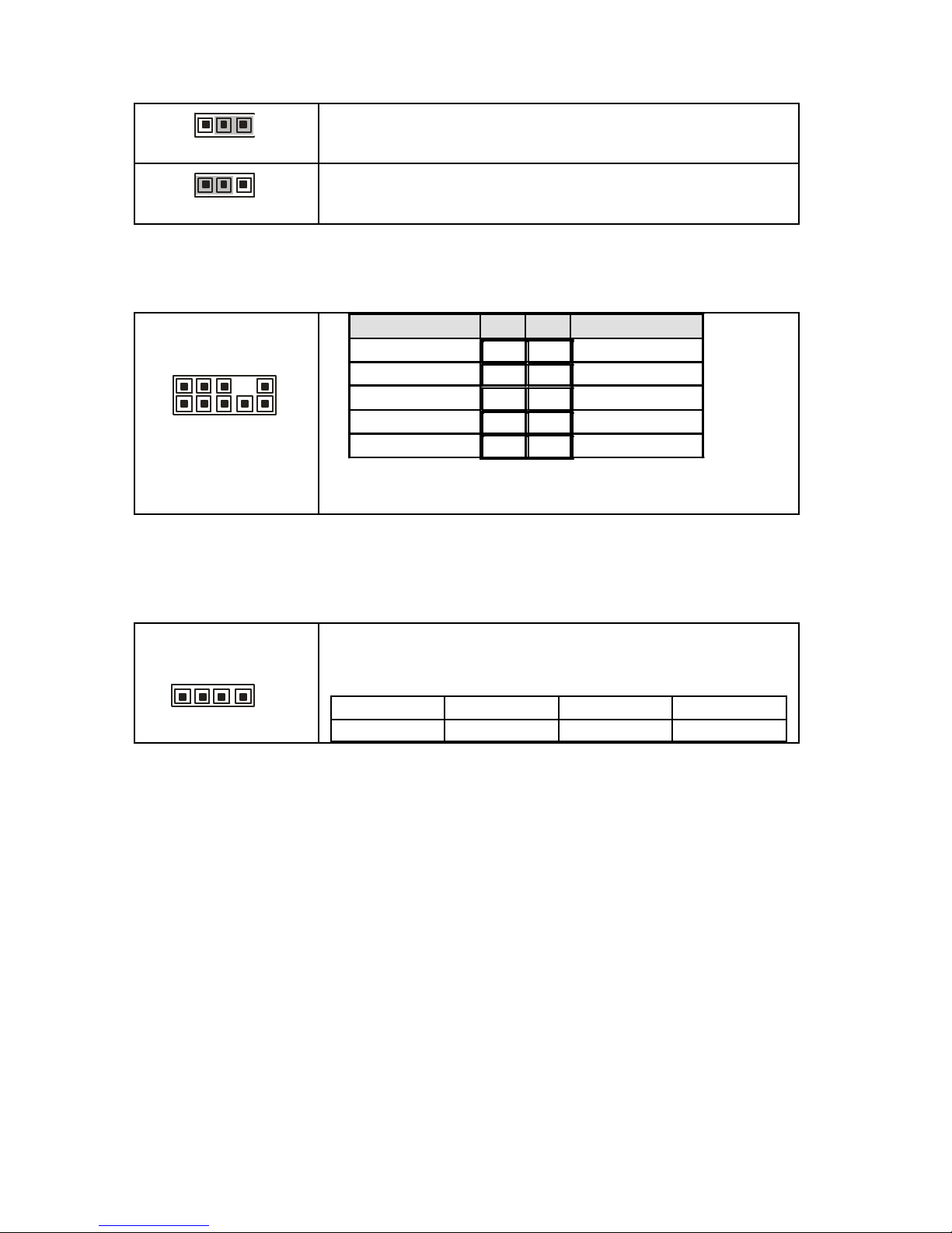
J24/J27: Front Panel USB2.0 Connectors
10 2
9 1
Signal Pin Pin
Signal
USB PWR 1 2 USB PWR
USB1- 3 4 USB2-
USB1+ 5 6 USB2+
GND 7 8 GND
_ 9 10
GND
Use these headers to connect to the USB devices
via the enclosed USB cable.
J24: USB3, J27: USB4
J25: Front Panel LAN1/LAN2 ID LED Headers
1 11
2 12
Signal Pin Pin Signal
LAN1 LED+ 1 2 LAN1 LEDLAN2 LED+ 3 4 LAN2 LED-
NC 5 6 NC
IDLED+ 7 8 IDLED-
ID S/W+ 9 10 ID S/W-
NC
11 12
_
Use these headers to connect the front panel dual color
LEDs to indicate the speed of LAN1, LAN2 and ID LED.
JP5: Clear CMOS Jumper
1
3
Normal
(Default)
3
1
Clear
Use this jumper when you forgot your system/setup
password or need to clear system BIOS setting.
How to clear the CMOS data
- Power off system and disconnect power
supply from AC source
- Use jumper cap to close Pin_2 and 3 for
several seconds to Clear CMOS
- Replace jumper cap to close Pin_1 and 2
Reconnect power supply to AC source
Power on system
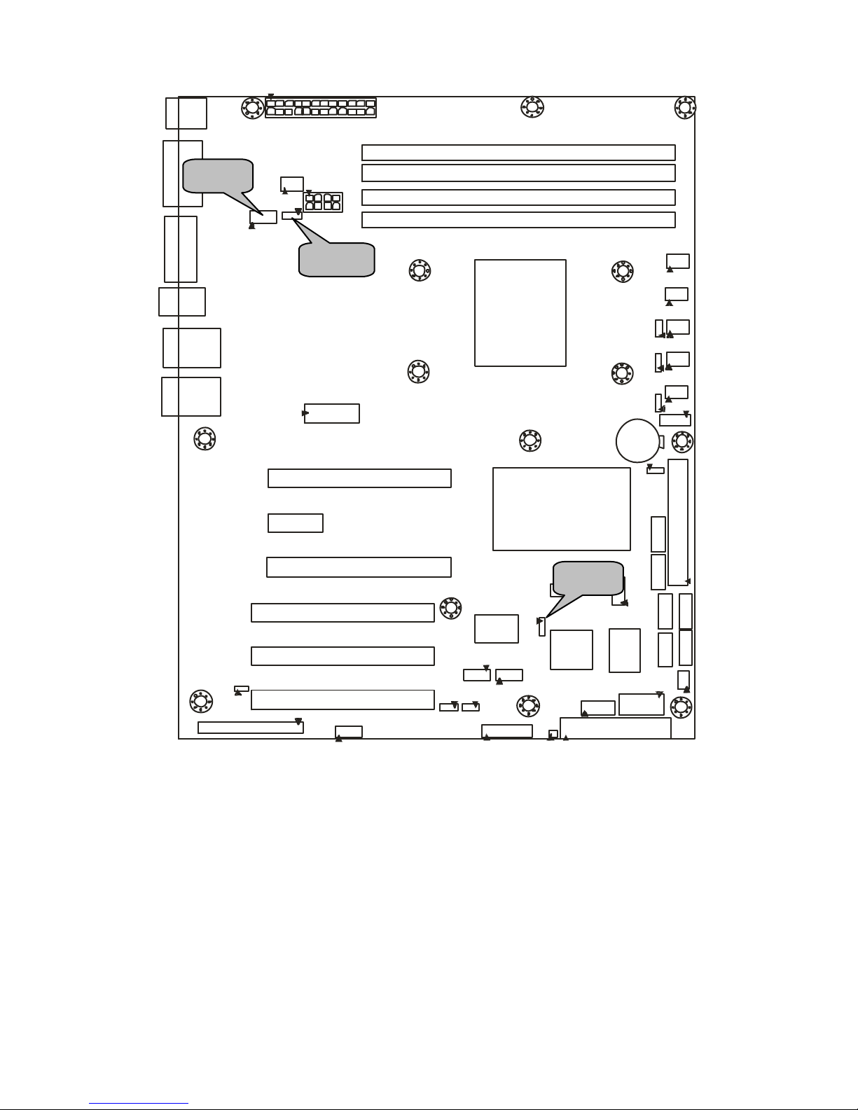
18
JP4 J11 J7
19
JP4: Enable VT6308(1394) Function Jumper
1
3
Enable the integrated 1394a function of VT6308 PCI
FireWire controller. (Default)
1
3
Disable the integrated 1394a function of VT6308 PCI
FireWire controller.
J7: Front Audio Header
1 9
2 10
Signal Pin Pin
Signal
Mic_L 1 2 GND
Mic_R 3 4 Key
Line_R 5 6 GND
_ 7 8 NC
Line_L 9 10
GND
Use this header to connect with the front panel
audio outputs.
J11: External CD-in Header
1
Use this header to connect to the external CD-in
device.
Pin 1 Pin 2 Pin 3 Pin 4
CDIN_L GND GND CDIN_R
20
J37 J35 J36 J10 J34 J33 SATA5
SATA4
SATA2
SATA3
SATA0
SATA1
21
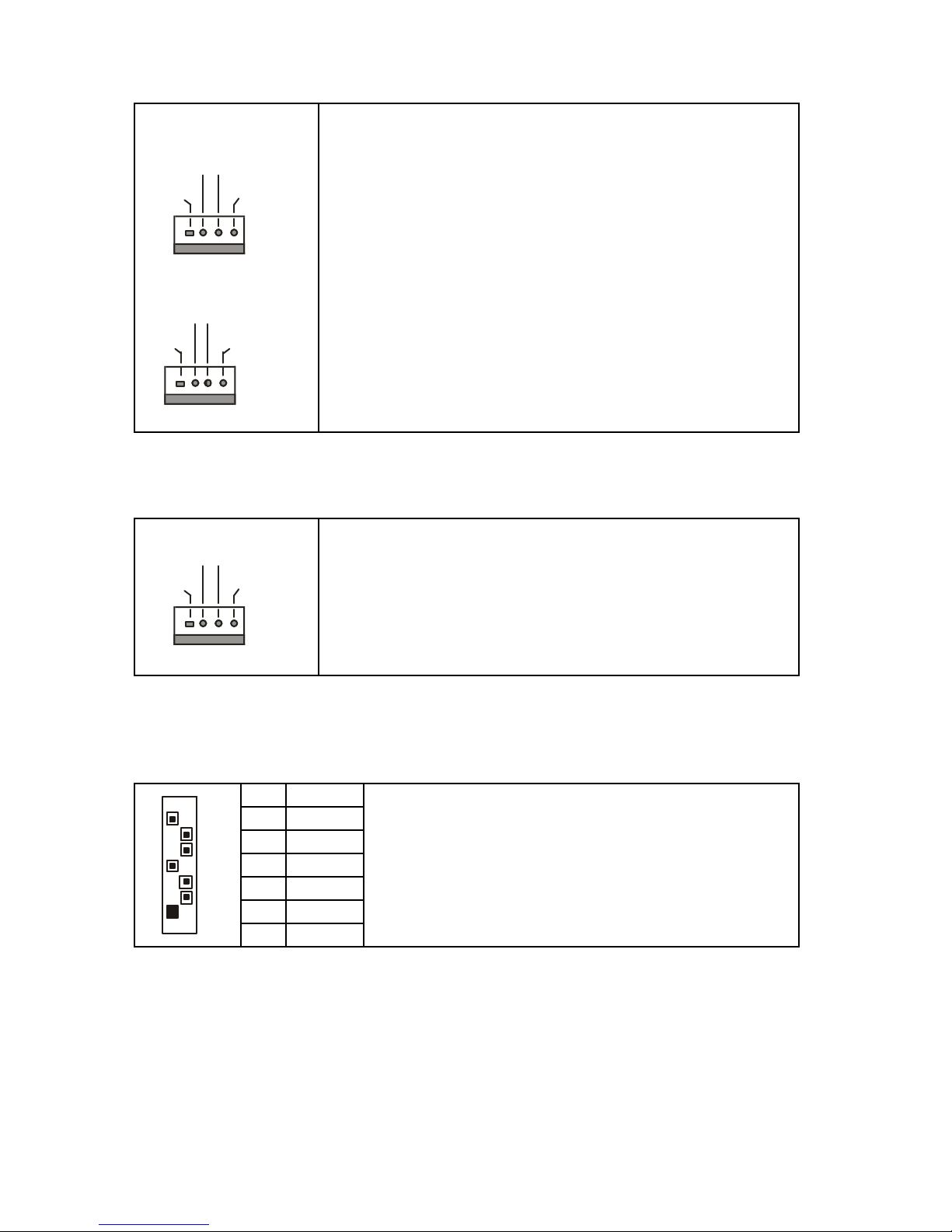
J34/J35/J36/J37/J10: Front Fan Connectors
J34/J35/J36/J37
+12V
PWM
GND
Tachometer
J10
+12V
NC
GND
NC
Use these headers to connect the chassis cooling fans
to your motherboard to keep the system stable and
reliable.
J34: FAN1, J35: FAN2, J36: FAN3, J37: FAN4
J10: FAN5
These connectors support the tachometer monitoring
and auto fan speed control.
J33: CPU FAN Connector
+12V
PWM
GND
Tachometer
Use this header to connect the processor cooling fan to
your motherboard to keep the system stable and
reliable.
This connector supports the tachometer monitoring and
auto fan speed control.
SATA 0/1/2/3/4/5: Serial ATA RAID Connectors
7 GND
6 RXP
5 RXN
4 GND
3 TXN
2 TXP
7
1
1 GND
Connects to the Serial ATA ready drives via the
Serial ATA cable
You may use any two of the six Serial ATA ports to
have the support of RAID 0, 1, 0+1, and 5 through
the onboard nVIDIA chip.
22
2.4 - Installing the Processor
Your brand new Tomcat n3400B S2925 supports the latest 64-bit processor
technology from AMD®. Only AMD® Opteron™ series processors are certified
and supported with this motherboard.
Check our website for latest processor support. http://www.tyan.com
TYAN is not liable for damage as a result of operating an unsupported
configuration.
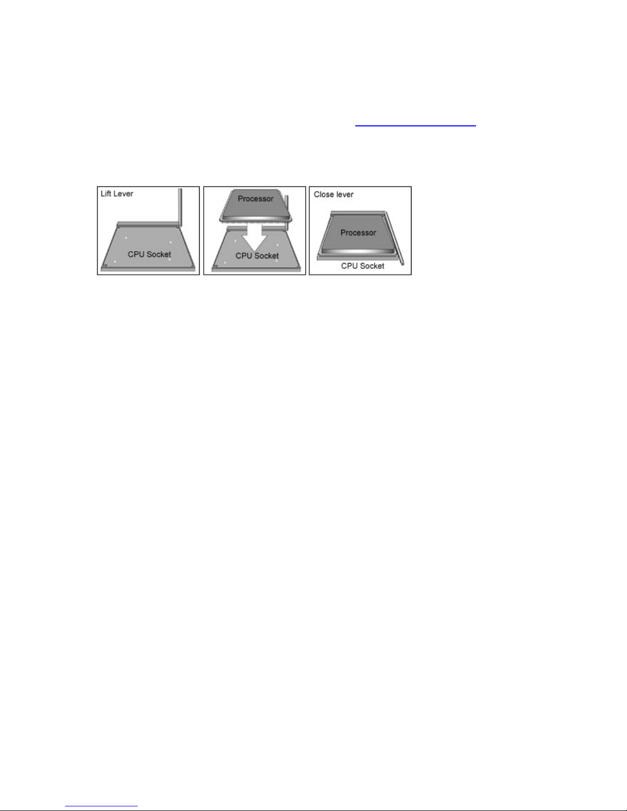
The diagram is provided as a visual guide to he lp you install the socket
processor and may not be an exact representation of the processor you have.
Step 1: Lift the lever on the socket until it is approxima tely 90o or as far back as
possible to the socket.
Step 2: Align the processor with the socket. There are keyed pins underneath
the processor to ensure that the processor’s installed correctly.
Step 3: Seat the processor firmly into the socket by gently pressing down until
the processor sits flush with the socket.
Step 4: Place the socket lever back down until it locks into place. The
installation is finished.
Take care when installing the processor as it ha s very fragile connector pins
below the processor and can bend and break if inserted improperly.
23
2.5 - Heatsink Retention Frame Installation
After you are done installing the processor, you should proceed to install the
retention frame and heatsink. The CPU heatsink will ensure that the processor
do not overheat and continue to operate at maximum performance for as long
as you own them. The overheated processor is dangerous to the motherboard.
The backplate assembly prevents excessive motherboard flexing in the area
near the processor and prov ides a base for the installation of the heatsink
retention bracket and heatsink.
Because there are many different types of heatsinks available from many
different manufacturers, a lot of them have their own method s of installation. For
the safest method of installation and information on choosing the appropriate
heatsink, use heatsinks validated by AMD. Please refer to AMD’s website at
www.amd.com.
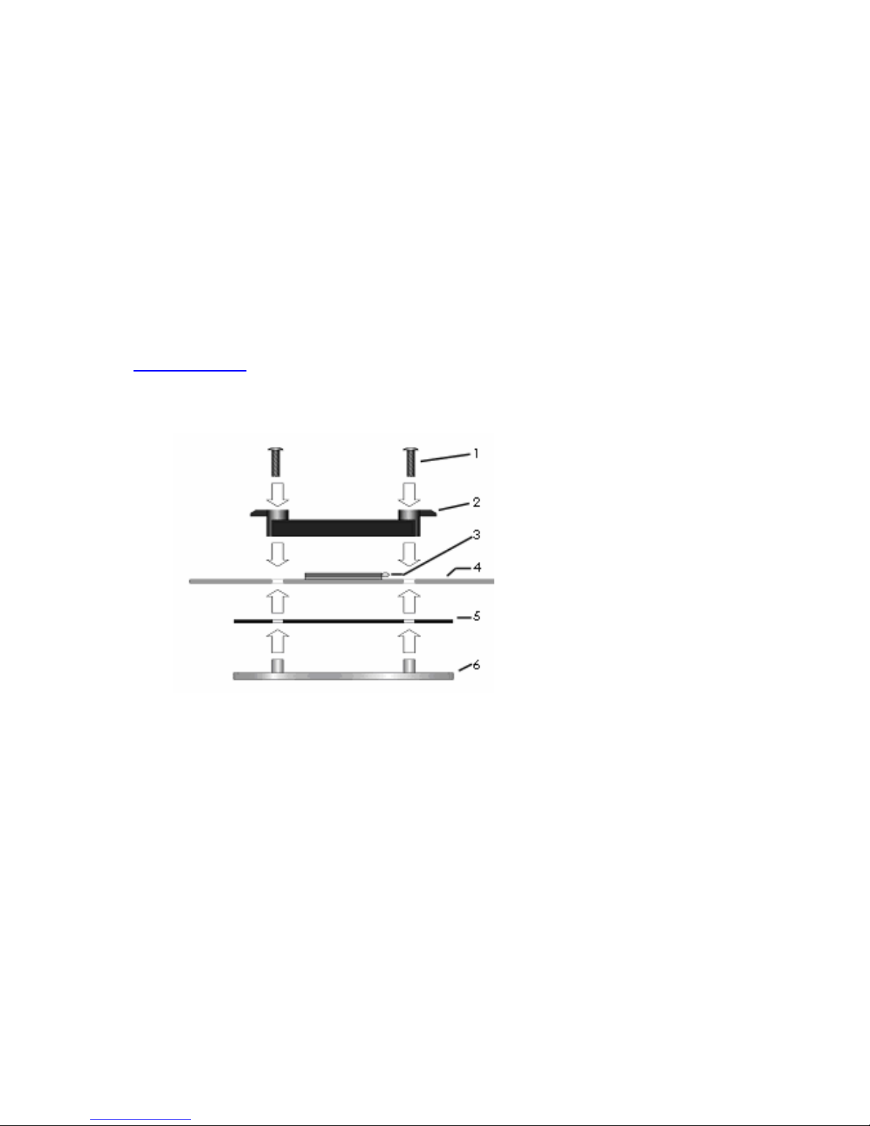
The following diagram will illustrate how to install the most common CPU back
plates:
1. Mounting screws
2. Heatsink retention frame
3. CPU socket
4. Motherboard PCB
5. Adhesive insulator
material
6. Backplate assembly
NOTE: Please see next
section for specific
instructions on how to install
mounting bracket.
24
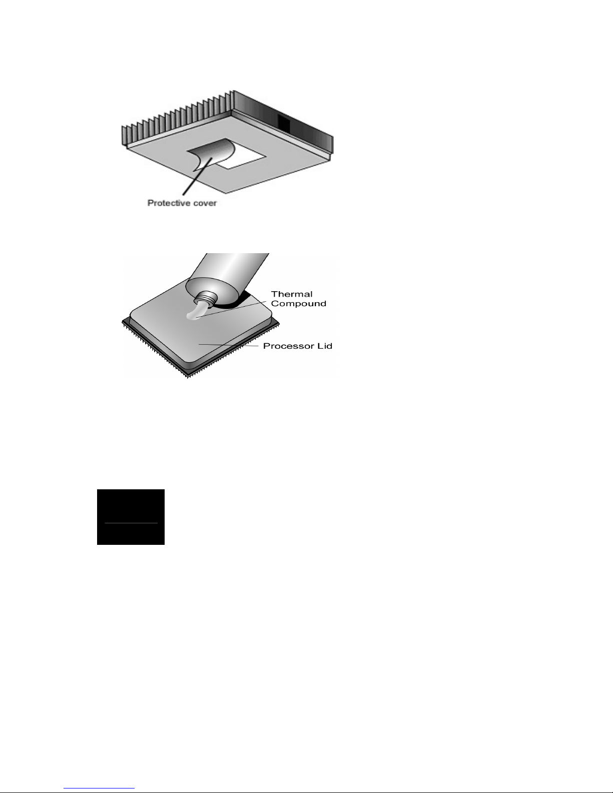
2.6 - Thermal Interface Material
There are two types of
thermal interface materials
designed for use with the
AMD® Opteron™
processors.
The most common material
comes as a small pad
attached to the heatsink at
the time of purchase. There
should be a protective cover
over the material. Take care
not to touch this material.
Simply remove the protective
cover and place the heatsink
on the processor.
The second type of interface
material is usually packaged
separately. It is commonly
referred to as ‘thermal
compound’. Simply apply a
thin layer on to the CPU lid
(applying too much will
actually reduce the cooling).
NOTE
Always check with the manufacturer of the heatsink &
processor to ensure the Thermal Interface material is
compatible wit h the processor & meets the manufacturer’s
warranty requirements
25
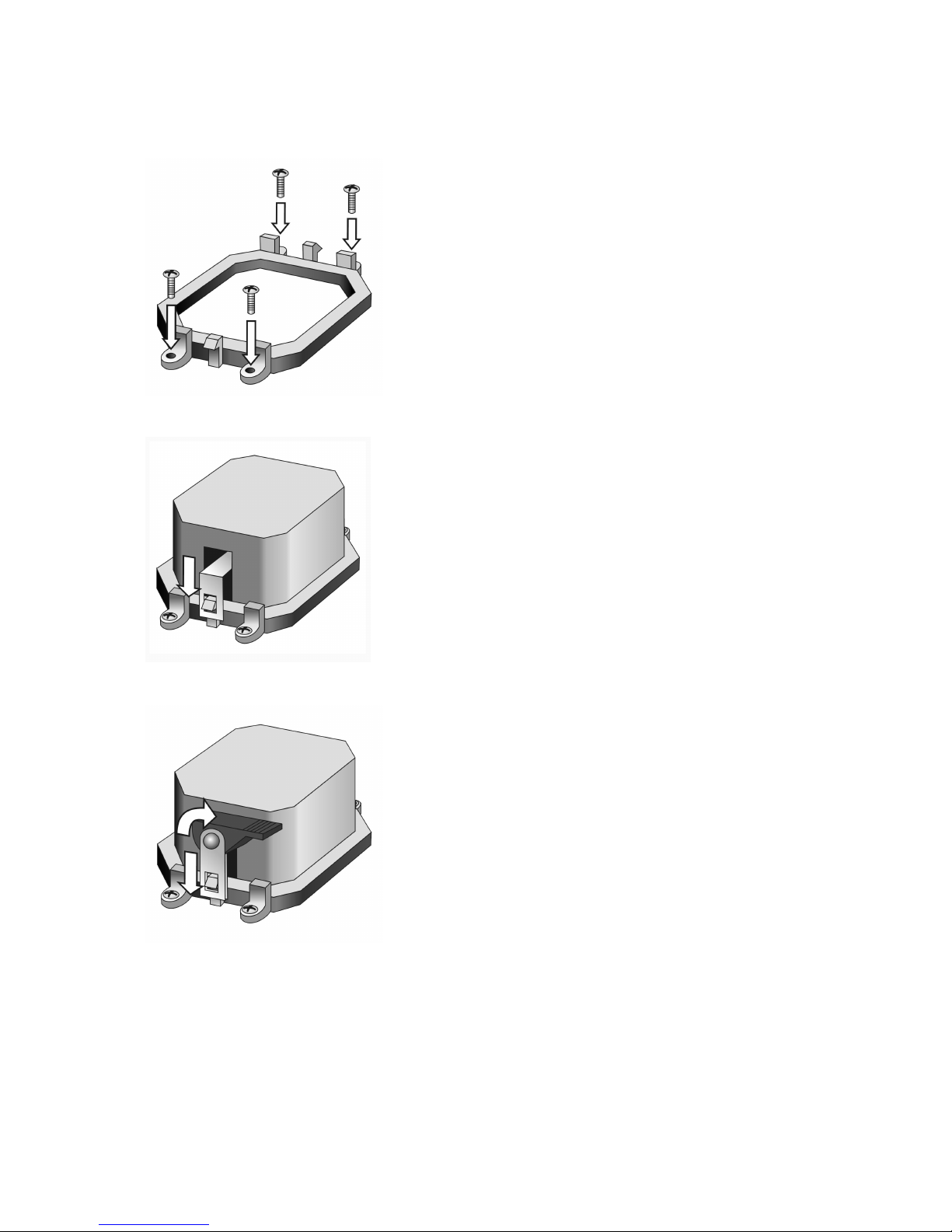
2.7 - Heatsink Installation Procedures
1. After placing backplate and
interface material under motherboard
place heatsink retention frame on top
of motherboard. Align plastic retention
bracket screw hole s with CPU backplate standoffs.
Tighten screws to secure plastic
retention bracket. Repeat for the other
side. DO NOT OVER TIGHTEN.
2. After tightening screws secure
metal clip to plastic retention bracket
center tab. Repeat for the other side
of heatsink.
3. After securing metal clip to plastic
retention bracket center tab, push
down on plastic clip to lock plastic clip
to side tab.
26
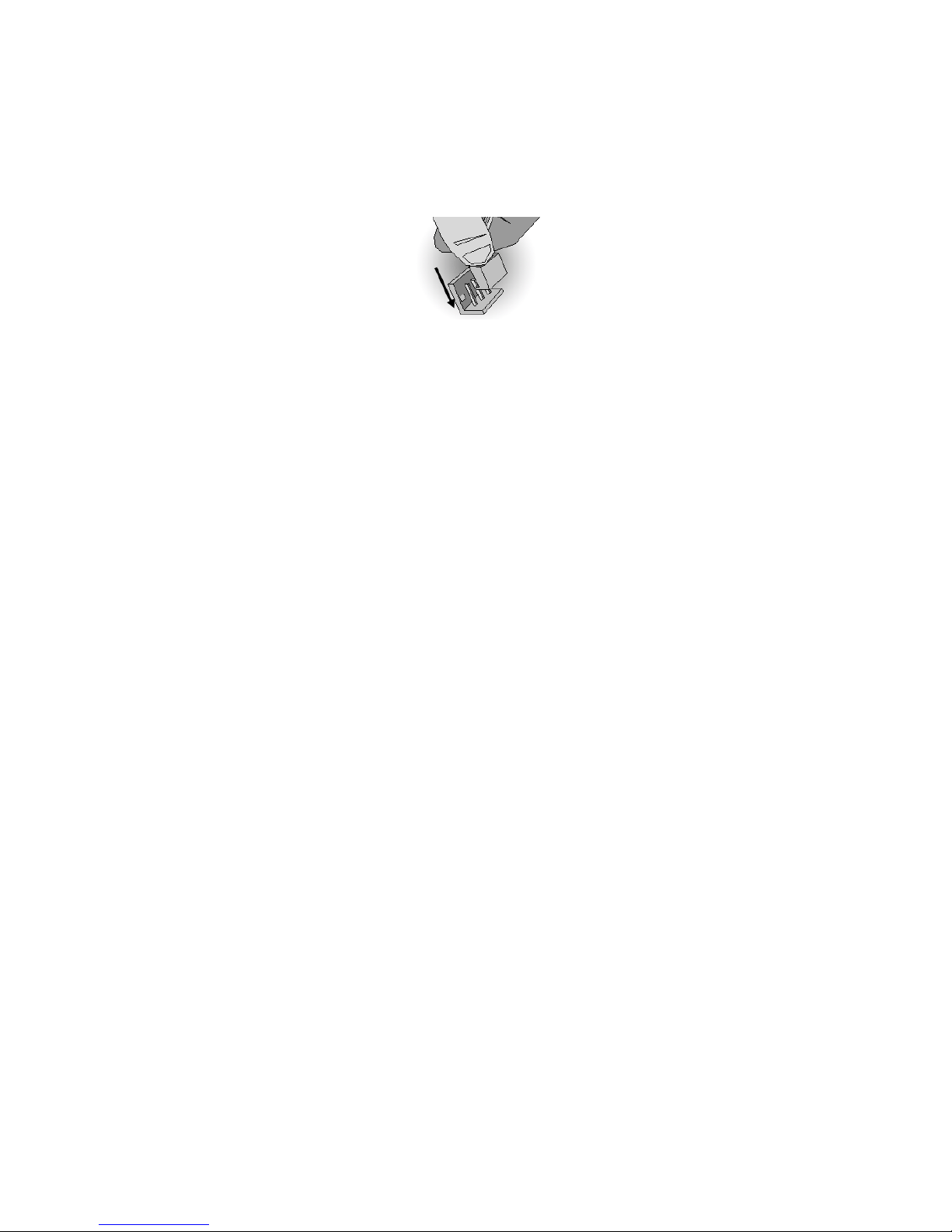
2.8 - Finishing Installing the Heatsink
After you have finished installing the heatsink onto the processor and
socket, attach the end wire of the fan (which should already be attached to
the heatsink) to the motherboard. The following diagram illustrates how to
connect fans onto the motherboard.
Once you have finishe d installing all the fans you can connect your drives
(hard drives, CD-ROM drives, etc.) to your motherboard.
27
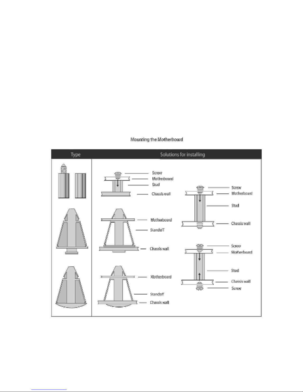
2.9 - Tips on Installing Motherboard in Chassis
Before installing your motherboard, make sure your chassis has the
necessary motherboard support studs installed. These studs are usually
metal and are gold in color. Usually, the chassis manufacturer will pre-install
the support studs. If you are unsure of stud placement, simply lay the
motherboard inside the chassis and align the screw holes of the
motherboard to the studs inside the case. If there are any studs missing,
you will know right away since the motherboard will not be able to be
securely installed.
Some chassis’ include plastic studs instead of metal. Although the plastic
studs are usable, TYAN recommends using metal studs with screws that will
fasten the motherboard more securely in place.
Below is a chart detailing what the most common motherboard studs look
like and how they should be installed.
 Loading...