

TYAN S2915-E User Manual

http://www.tyan.com
1
Thunder n6650W
///
S2915-E
Version 1.0
Copyright
Copyright © TYAN Computer Corporation, 2006. All rights reserved. No part of
this manual may be reproduced or translate d without prior written consent from
TYAN Computer Corp.
Trademark
All registered and unregistered trademarks and company names contained in
this manual are property of their respective owners including, but not limited to
the following.
TYAN, Taro and Thunder n6650W are trademarks of TYAN Computer
Corporation.
AMD, Opteron, and combinations thereof are trademarks of AMD Corp or ation.
Nvidia and nForce are trademarks of Nvidia Corporation
Microsoft, Windows are trademarks of Microsoft Corporation.
SuSE is a trademark of Novell, Inc.
Linux is a trademark of Linus Torvalds
IBM, PC, AT, and PS/2 are trademarks of IBM Corporation.
Winbond is a trademark of Winbond Electronics Corporation.
Notice
Information contained in this document is furnished by TYAN Computer
Corporation and has been reviewed for accuracy and reliability prior to printing.
TYAN assumes no liability whatsoever, and disclaims any express or implied
warranty, relating to sale and/or use of TYAN products including liability or
warranties relating to fitness for a particular purpose or merchantability. TYAN
retains the right to make changes to product descriptions and/or specifications
at any time, without notice. In no event will TYAN be held liable for any direct or
indirect, incidental or consequential damage, loss of use, loss of data or other
malady resulting from errors or inaccuracies of information contained in this
document.

http://www.tyan.com
2
Table of Contents
Chapter 1: Introduction
1.1 Congratulations Page 5
1.2 Hardware Specifications Page 5
Chapter 2: Board Installation
2.1 Board Image Page 8
2.2 Block Diagram Page 10
2.3 Board Parts, Jumpers and Connectors Page 11
2.4 Tips on Installing Motherboard in Chassis Page 21
2.5 Installing the Processor(s) Page 22
2.6 Installing the Memory Page 25
2.7 Attaching Drive Cables Page 28
2.8 Installing Add-In Cards Page 30
2.9 Connecting External Devices Page 31
2.10 Installing the Power Supply Page 32
2.11 Finishing Up Page 33
Chapter 3: BIOS
3.1 About the BIOS Page 35
3.2 Main BIOS Setup Page 37
3.3 Main Menu Page 38
3.4 Advanced Menu Page 40
3.5 Security Menu Page 58
3.6 Boot Menu Page 59
3.7 Power Menu Page 60
3.8 Exit Menu Page 61
Chapter 4: Diagnostics
4.1 Flash Utility Page 63
4.2 Phoenix BIOS Post Code Page 64
Appendix I: How to Make a Driver Diskette Page 67
Glossary Page 69
Technical Support Page 75
http://www.tyan.com
3
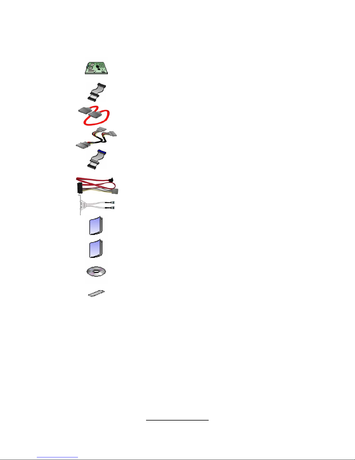
Check the box contents!
The retail motherboard package should contain the following:
1x Thunder n6650W motherboard
1x 34-Pin floppy drive cable
6 x SATA cable
3 x SATA Drive Power Adapter
1 x Ultra-DMA-100/66 IDE cable
2 x SAS cable (for S2915WA2NRF-E only)
1 x IEEE1394 cable
1 x Thunder n6650W User’s Manual
1 x Thunder n6650W Quick Reference Guide
1 x TYAN driver CD
1 x I/O shield
If any of these items are missing, please contact your vendor/dealer for
replacement before continuing with the installation process.

http://www.tyan.com
4
NOTE

http://www.tyan.com
5
Chapter 1: Introduction
1.1 - Congratulations
You have purchased one of the most powerful server solutions available. The
Thunder n6650W (S2915-E) is a high-end server motherboard, based on the
NVIDIA NFP3600 and NFP3050 chip sets. It also includes the NEC nPD72044
PCI-X tunnel and SMsC 5307 Super I/O chipsets.
This motherboard is designed to support two AMD Opteron 2000 Series
processors and up to 32GB of DDR2 400/533/667 memory. The S2915-E is
ideal for CPU, memory, and I/O intensive applications required in the HPC
(High Performancec Computing) and clustering environments.
The S2915-E is
also ideal for computing and graphics acceleration applications required in the
HPC/clustering environments or workst at ion platforms.
Remember to visit TYAN’s website at http://www.tyan.com
. There you can find
information on all of TYAN’s products with FAQs, online manuals and BIOS
upgrades.
1.2 - Hardware Specifications
Processors
• Dual 1207-pin sockets
• Supports up to 2 x AMD Opteron
Rev.F 2000 series Dual-core / Quadcore processors.
• Up to 1.0GHz Hyper-Transport link
support
• AMD Dual Dynamic Power support
Chipset
• NVIDIA NFP3600 + NFP3050
• NEC nPD720404 PCI-X tunnel
• SMsC 5307 Super I/O controller
Integrated I/O
•
One 9-pin 16550 UART serial port
•
10 USB 2.0 ports (6 at rear, 1 internal
vertical connector, and 3 front ports
via optional cables)
•
PS/2 mouse and keyboard connectors
•
6 SATA-II connectors
•
Dual RJ-45 10/100/1000 LAN ports
•
One IDE and one Floppy connectors
System Management
Memory
•
Dual-channel memory bus
• Eight DDR2 sockets (four per CPU)
• Supports ECC Registered DIMMs
• Maximum of 32GB DDR2-
400/533/667
Integrated Network Processor
•
Two GbE via Marvell PHY 88E1121
• Supports WOL and PXE
• Two RJ-45 ports with LEDs
Integrated FireWire (1394a)
Controller
•
TI TSB43AB22A 1394a PCI controller
• 1394a channel for rear (connector)
• 1394a channel for front (header)
Integrated Audio Controller
•
HDA link
• RealTek ALC262 controller (High
Definition Audio)
• Line-in, Line-out, Mic-in rear ports
• SPDIF-out in rear

http://www.tyan.com
6
•
CPU thermal & voltage monitor
support
• Six 4-pin fan header (PWM and
tachometer support)
• One 2-pin chassis intrusio n he ader
• Watchdog timer support
Expansion Slots
•
Four (4) PCI Express x16 slots
- one x16 signal from NFP3050
- one x16 from NFP3600 PRO
- one x16 from NFP3600 PRO with x8
signal
- one x16 from NFP3050 with x8 signal
• Two (2) PCI-X 100/133MHz slots from
NEC nPD720404
• One (1) PCI 32-bit 33MHz slot
• Seven (7) expansion slots total
Form Factor
•
SSI / Extended ATX (12” x 13”)
• EPS 12V/SSI (24 + 8 + 4 pin) power
connectors
• Stacked PS/2 keyboard and mouse
connectors
• Stacked Serial (1) connector
• Stacked USB 2.0 (2) + FireWire (1)
connectors
• 2 stacked USB 2.0 (2) + RJ-45 (1)
connectors
• Stacked Line-in, Line-out, Mic-in audio
connectors
• SPDIF-out
• Front panel audio header
• CD-in, Aux-in headers (4-pin
configuration)
Integrated Serial ATA Controller
•
(6) SATA-II ports at 3.0Gb/ s per
direction per channe l
• Serial ATA II specification compliant
• NV RAID 0, 1, 0+1, 5, JBOD support
• SATA activity LED connector
Integrated SAS Controller
(for S2915WA2NRF-E only)
•
LSI 1068E SAS controller
• Eight SAS ports
BIOS
•
Phoenix BIOS on 8Mbit LPC Flash
ROM
• Supports ACPI (S0, S1, S3, S4, S5)
• Serial console Redirect
• PXE via Ethernet, USB device boot
• PnP, DMI 2.0, WfM 2.0 Power
Management
• User-configurable H/W monitoring
• Auto-configuration of hard disk types
• Multiple boot options
• 48-bit LBA support
Regulatory
•
FCC Class B (DoC)
• European Community CE (DoC)

http://www.tyan.com
7
Chapter 2: Board Installation
Precautions: The Thunder n6650W supports SSI, EPS12V type power
supplies (24pin + 8pin +4pin) and will not operate with any other types. For
proper power supply installation procedures see page 32.
DO NOT USE ATX 2.x or ATXGES power supplies as they will damage the
board and void your warranty.
How to install our products right… the first time
The first thing you should do is reading this user’s manual. It contains important
information that will make configurat ion and setup much easier. Here are some
precautions you should take when installing your motherboard:
(1) Ground yourself properly before removing your motherb oard from the
antistatic bag. Unplug the power fr om your computer power supply and
then touch a safely grounded object t o release static charge (i.e. power
supply case). For the safest conditions, TYAN recommen ds wearing a
static safety wrist strap.
(2) Hold t he motherboard by its edges and do not touch the bottom of the
board, or flex the board in any way.
(3) Avoid touching the motherboard components, IC chips, connectors,
memory modules, and leads.
(4) Place the motherboard on a grounded antistatic surface or on the
antistatic bag that the board was shipped in.
(5) Inspect the board for damage.
The following pages include details on how to install your motherboard into your
chassis, as well as installing the processor, memory, disk drives and cables.
NOTE
DO NOT APPLY POWER TO THE BOARD IF IT HAS BEEN
DAMAGED.
http://www.tyan.com
8
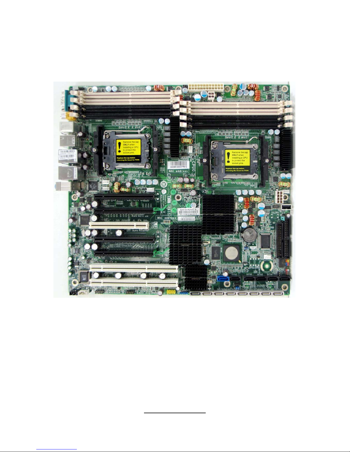
2.1- Board Image
This picture is representative of the latest board revision available at
the time of publishing. The board you receive may or may not look
exactly like the above picture.
The following page includes details on the vital components of this
motherboard.
http://www.tyan.com
9
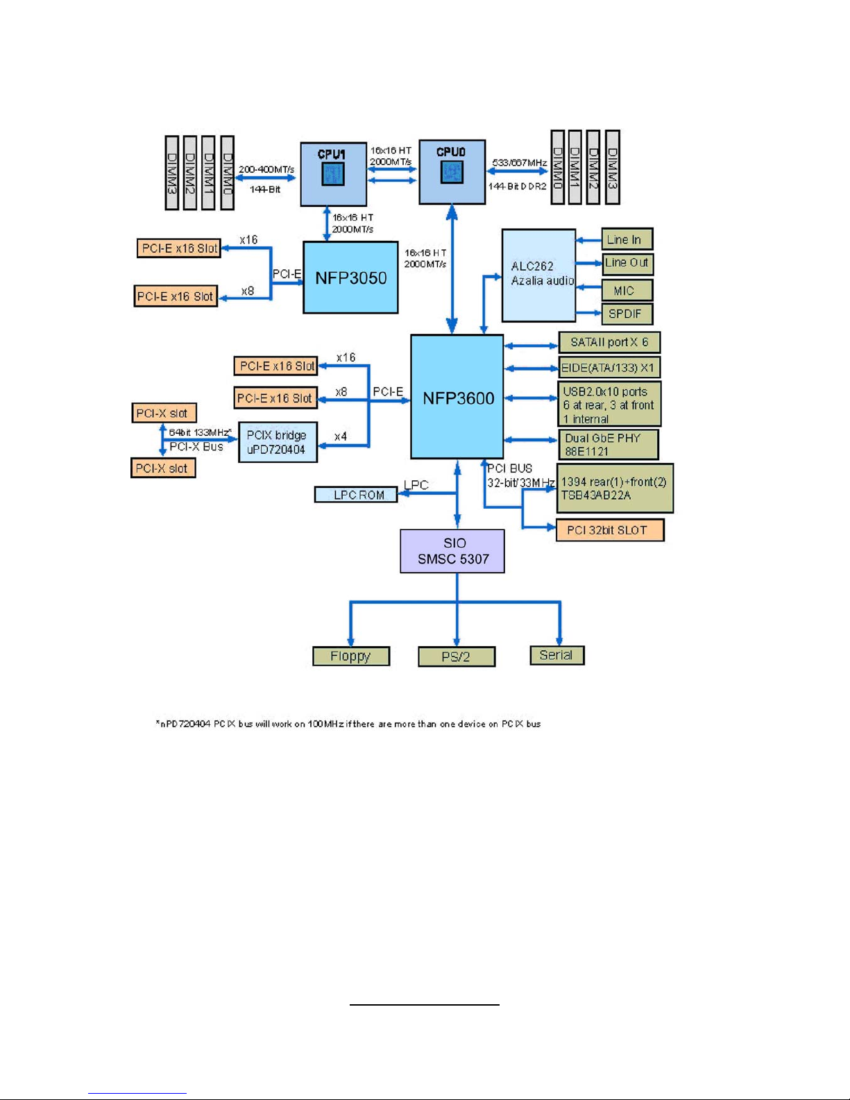
2.2 - Block Diagram
Thunder n6650W (S2915A2NRF-E) Block Diagram

http://www.tyan.com
10
Thunder n6650W (S2915WA2NRF-E) Block Diagram
http://www.tyan.com
11
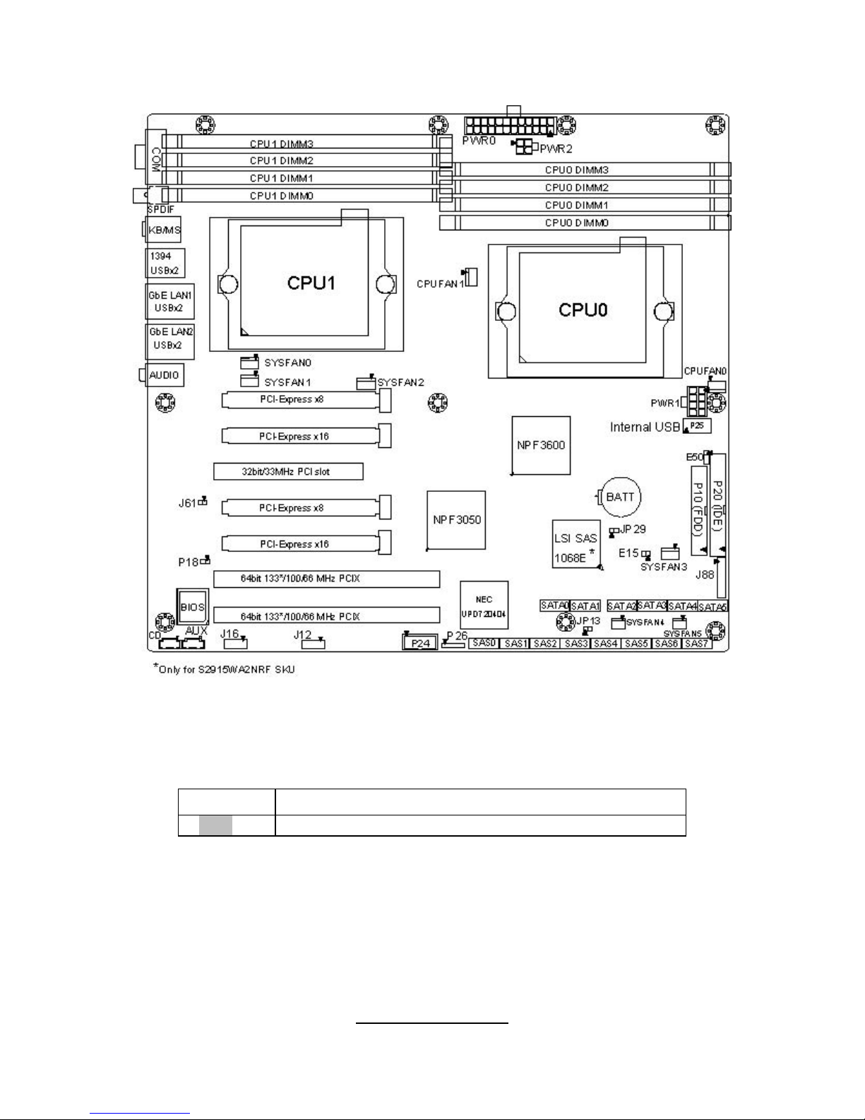
2.3 - Board Parts, Jumpers and Connectors
This diagram is representative of the latest board revision available at the time of
publishing. The board you receive may not look exactly like the above diagram.
Jumper Legend
OPEN - Jumper OFF, without jumper covered
CLOSED – Jumper ON, with jumper covered
http://www.tyan.com
12
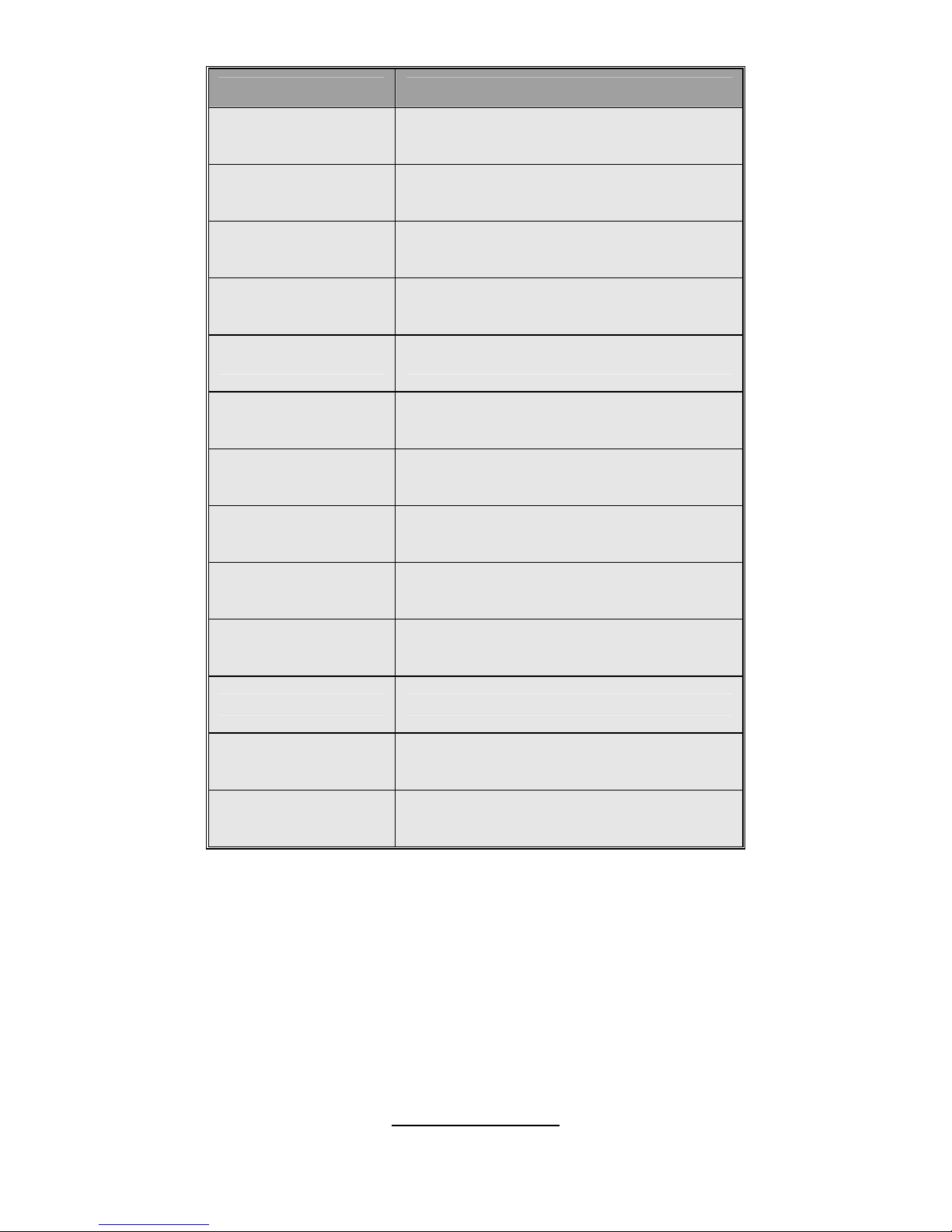
Jumper/Connector Function
J12 1394 Pin Header
J16 High Definition Audio Header
E15 Chassis Intrusion Header
P24 USB Pin Header
P26 USB Pin Header
P7 CD_IN Connector
P11 AUX_IN Connector
P18 SPDIF_IN Connector
J61 1394 Disable Jumper
JP29 SAS Disable Jumper
JP13 PCI-X Speed Select Jumper
E50 Clear CMOS Jumper
J88 Front Panel Header
http://www.tyan.com
13
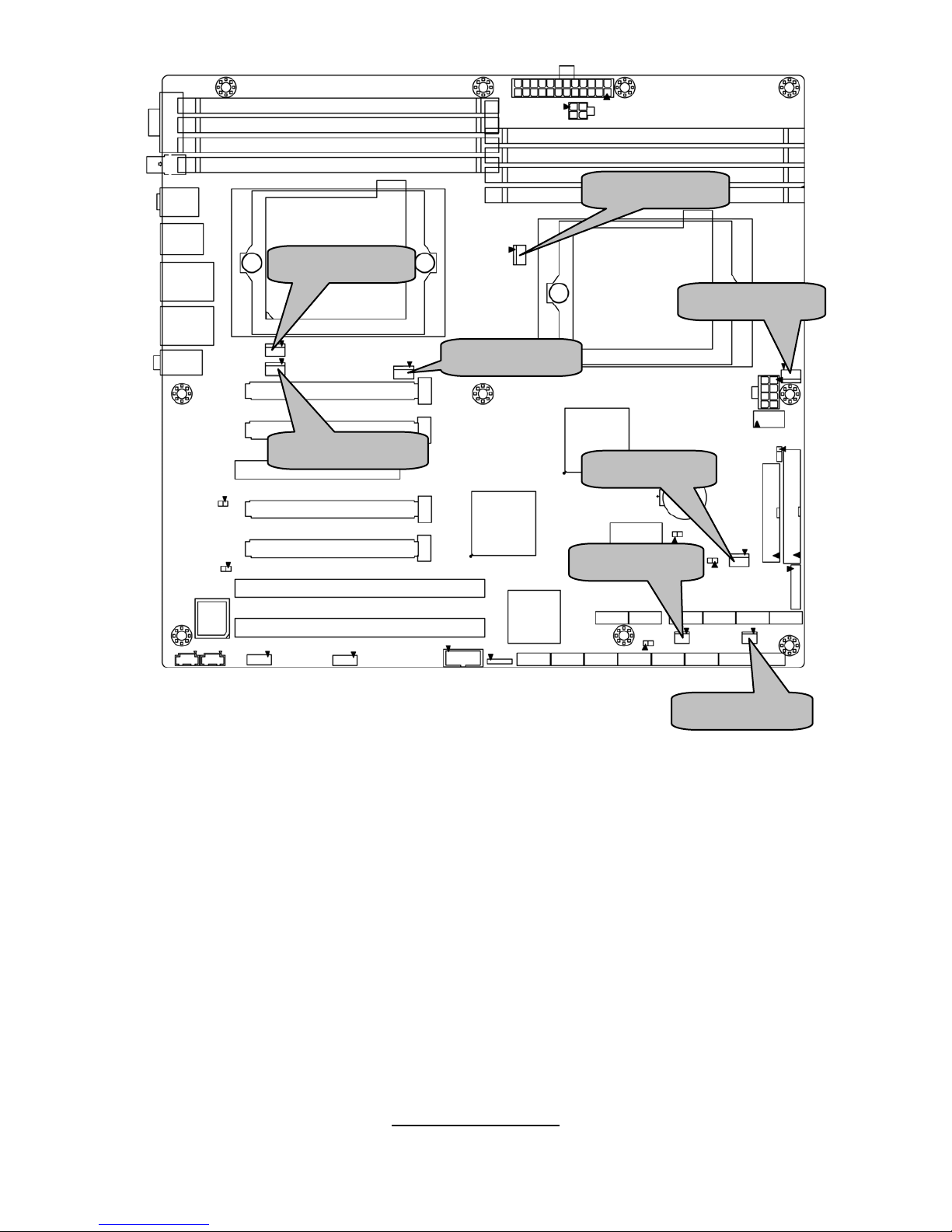
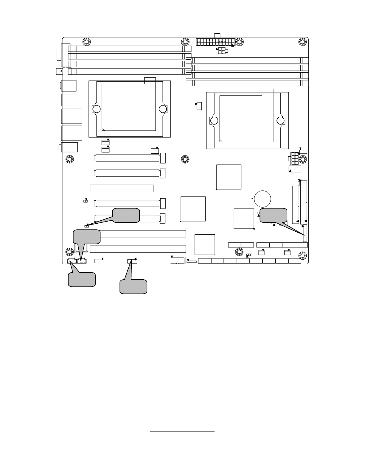
CPUFAN1
SYSFAN5
SYSFAN1
SYSFAN2
SYSFAN0
CPUFAN0
SYSFAN4
SYSFAN3
http://www.tyan.com
14
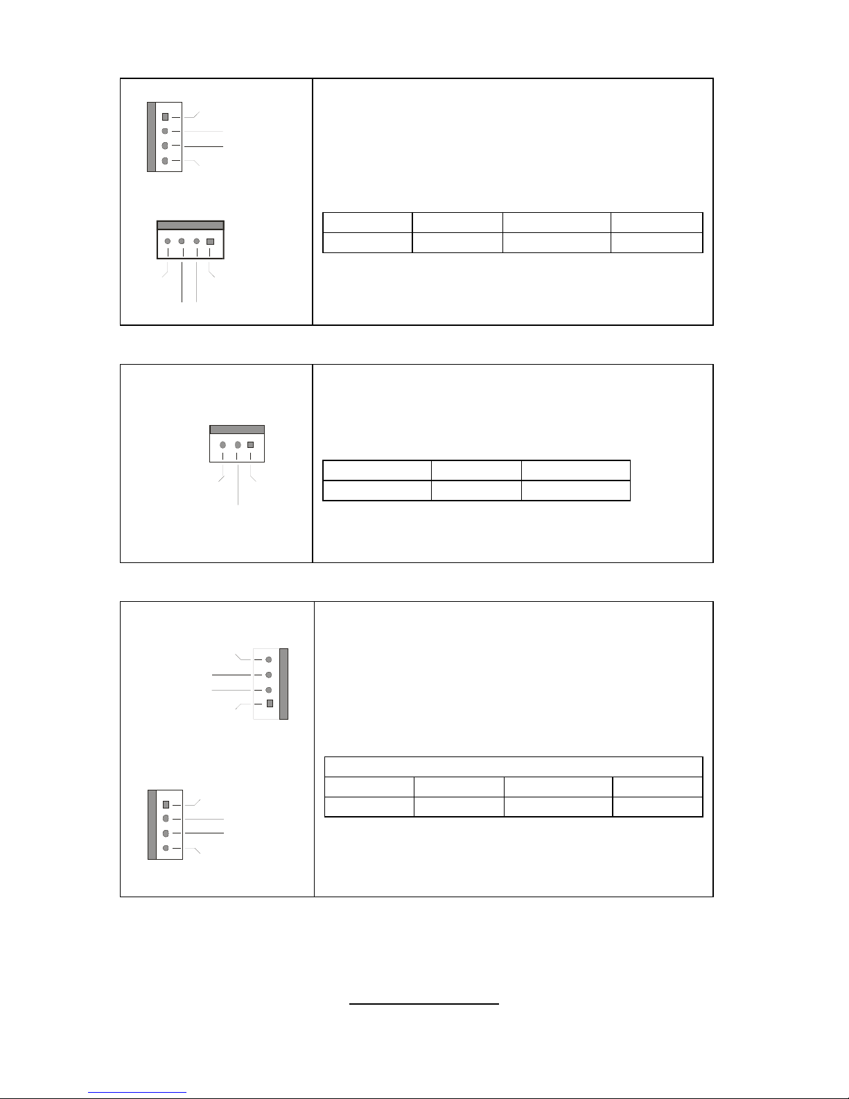
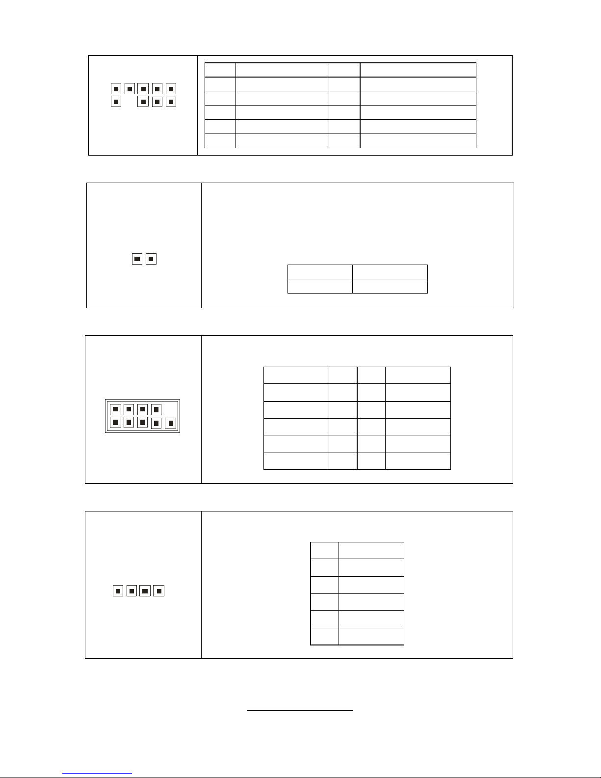
SYSFAN0/1/2/3: 4-pin Fan Connector with Speed Control
+12V
PW
M
GN
D
Tachometer
1
+12V
PWM
GND
Ta ch ome ter
1
Use these headers to connect the cooling fans to
the motherboard to keep the system stable and
reliable.
This connector supports the tachometer monitoring
and auto fan speed control.
Pin 1 Pin 2 Pin 3 Pin 4
GND +12V Tachometer PWM
SYSFAN4/5: 3-pin Fan Connector
+12V
GND
Ta ch om ete r
Use these headers to connect the cooling fans to
the motherboard to keep the system stable and
reliable.
Pin 1 Pin 2 Pin 3
Tachometer +12V GND
CPUFAN0/CPUFAN1: 4-pin Fan Connector
CPUFAN0
+12V
NC
GND
Ta ch om ete r
1
CPUFAN1
+12V
NC
GND
Tachometer
1
Use these headers to connect cooling fans to the
motherboard to keep the system stable and
reliable.
CPUFAN0 & CPUFAN1
Pin 1 Pin 2 Pin 3 Pin 4
GND +12V Tachometer NC
http://www.tyan.com
15
E15
P24
J16
P26
http://www.tyan.com
16
J16: High Definition Audio Header
10 2
9
1
Pin Signal Pin Signal
1 PORT1L 2 GND
3 PORT1R 4 PRESENCE#
5 PORT2R 6 SENSE1_RETURN
7 SENSE_SEND 8 KEY
9 PORT2L 10 SENSE2_RETURN
E15: Chassis Intrusion Header
1
This connector is connected to a 2-pin chassis switch. If
the chassis is opened, the system will then record this
status and show a warning message on the screen. To
clear the warning, you must enter the BIOS utility and
clear the record.
Pin 1 INTRUDER
Pin 2 GND
P24: USB Pin Header
1
9
2 1
0
Use this header to connect to front panel USB connector.
Signal Pin Pin Signal
VCC 1 2 VCC
USB DATA- 3 4 USB DATA-
USB DATA+ 5 6 USB DATA+
GND 7 8 GND
KEY 9 10 NC
P26: USB Pin Header
1
5
Use this header to connect to a USB connector.
Pin Signal
1 VCC
2 USB DATA3 USB DATA+
4 GND
5 KEY
http://www.tyan.com
17
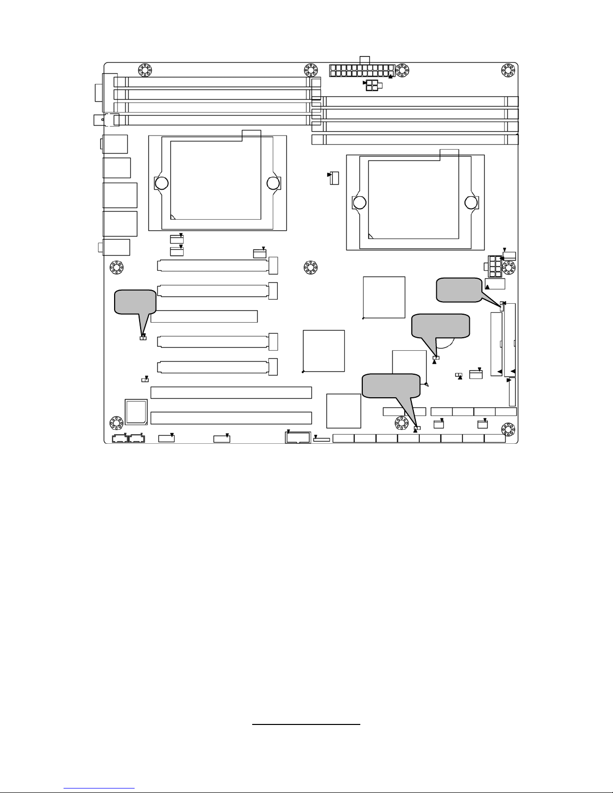
P18
P11
P7
J12
J88
http://www.tyan.com
18
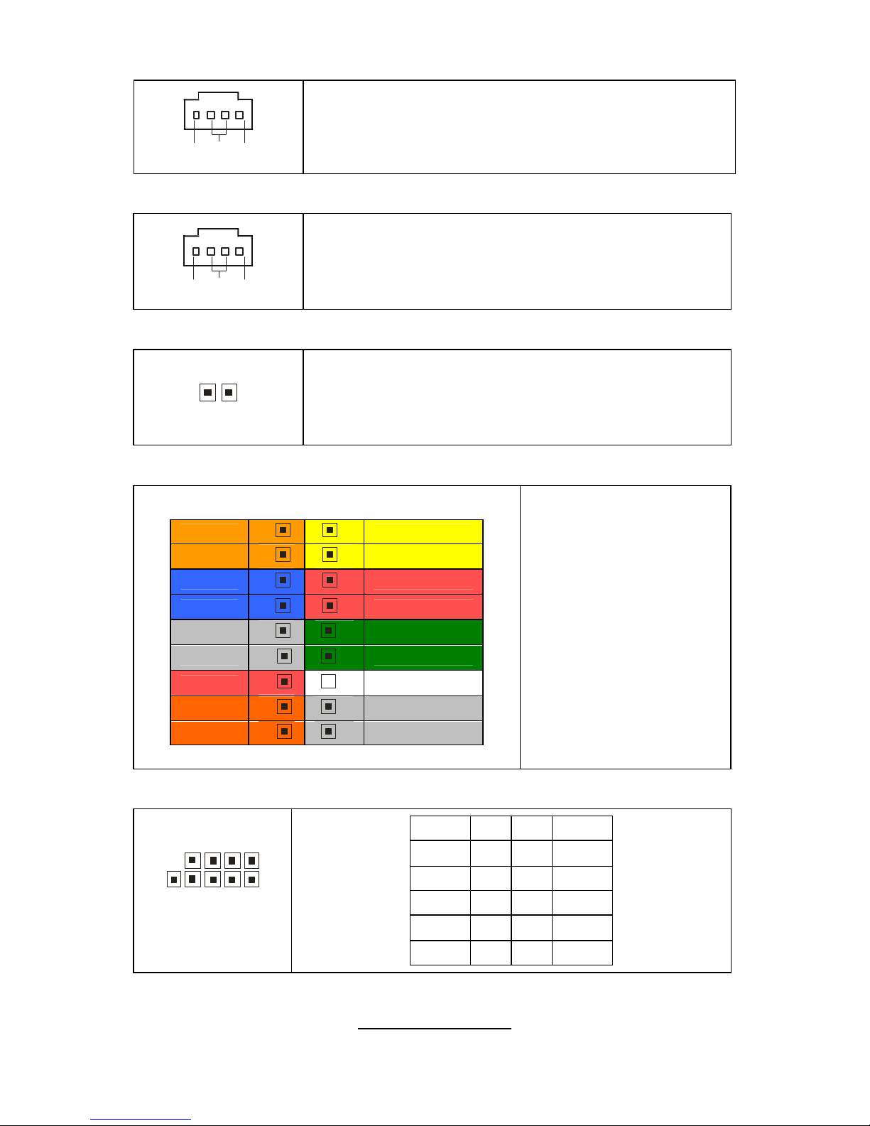
P7: CD_IN Connector
RGND
L
This is for CD-ROM audio connector.
P11: AUX_IN Connector
RGND
L
This connector is used for DVD Add-on Card with
Line_In Connector.
P18: SPDIF_IN Connector
1
This connector is used to connect SPDIF (Sony &
Philips Digital Interconnect Format) interface for
digital audio transmission.
J88: Front Panel Header
HDD LED+
1 2
Power LED+
HDD LED-
3 4
Power LED-
GND
5 6
Power S/W+
Reset SW+
7 8
GND
GND
9 10
NC
NC
11 12
GND
5VSB
13 14
Key
NC
15 16
GND
NC
17 18
INTRU#
The motherboard
provides one front panel
header for electrical
connection to the front
panel switches and
LED’s.
J12: 1394 Pin Header
10 2
9 1
Signal Pin Pin Signal
TPA+ 1 2 TPA-
GND 3 4 GND
TPB+ 5 6 TPB-
+12V 7 8 +12V
KEY 9 10 GND
http://www.tyan.com
19
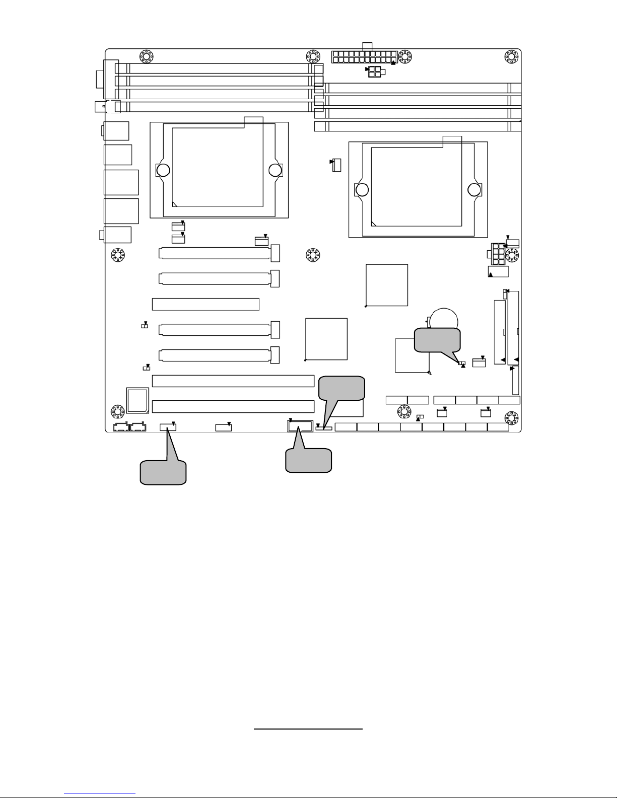
JP13
E50
JP29
J61
http://www.tyan.com
20
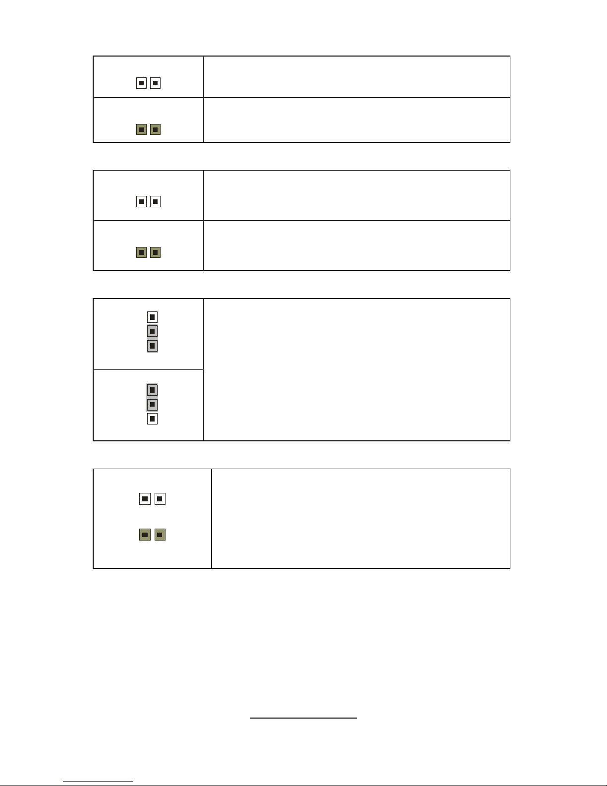
JP13: PCI-X Speed Select Jumper
1
Open: 133MHz (Default)
1
Closed: Force to run at 100MHz
JP29: SAS Disable Jumper
1
Open: Enable SAS Controller (Default)
1
Closed: Disable SAS Controller
E50: Clear CMOS Jumper
1
3
(Clear)
1
3
(Default)
If you have lost your system/setup password or need to
clear the system BIOS settings, you can reset the
CMOS settings by using this jumper.
Power off the system and set E50 to (2-3) position, and
then power on to boot up the system. The CMOS will
be cleared when the screen is on. Finally shut down
the power, replace E50 to the default setting (1-2),
power on the system again.
J61: 1394 Disable Jumper
1
1
Open: Enable 1394 functionality (Default)
Closed: Disable 1394 functionality
http://www.tyan.com
21
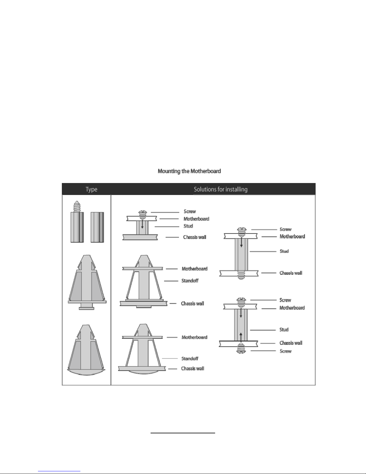
2.4 - Tips on Installing Motherboard in Chassis
Before installing your motherboard, make sure your chassis has the
necessary motherboard support studs installed. These studs are usually
metal and are gold in color. Usually, the cha ssis manufacturer will pre-install
the support studs. If you are unsure of stud placement, simply lay the
motherboard inside the chassis and align the screw holes of the
motherboard to the studs inside the case. If there are any studs missing,
you will know right away since the motherboard will not be able to be
securely installed.
Some chassis’ include plastic studs instead of metal. Although the plastic
studs are usable, TYAN recommends using metal studs with screws that will
fasten the motherboard more securely in place.
Below is a chart detailing what the most common motherboard studs look
like and how they should be installed.
http://www.tyan.com
22
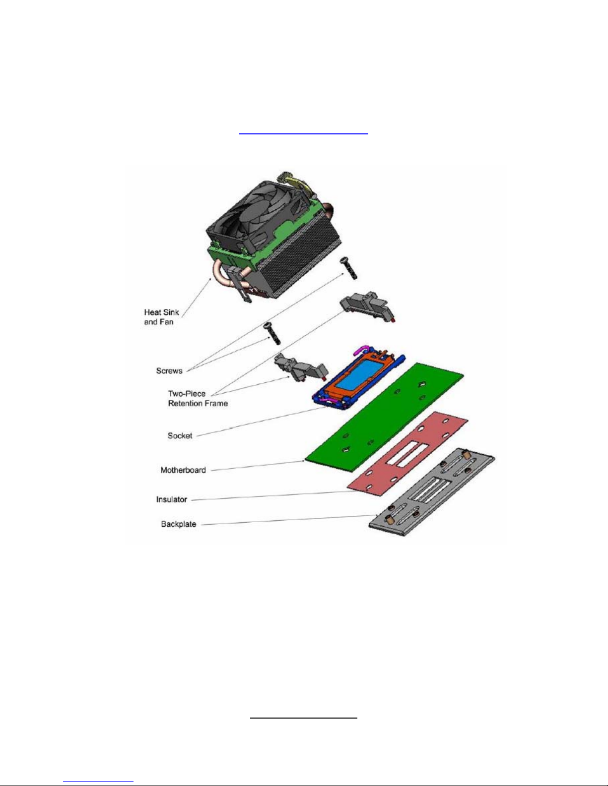
2.5 - Installing the Processor(s)
Your S2915 supports the latest processor technologies from AMD.
Check the TYAN website for latest processor support:
http://www.tyan.com
Figure 1. Detailed View of the Thermal Solution AMD PIB Platforms based on the
AMD Socket F Processor
http://www.tyan.com
23
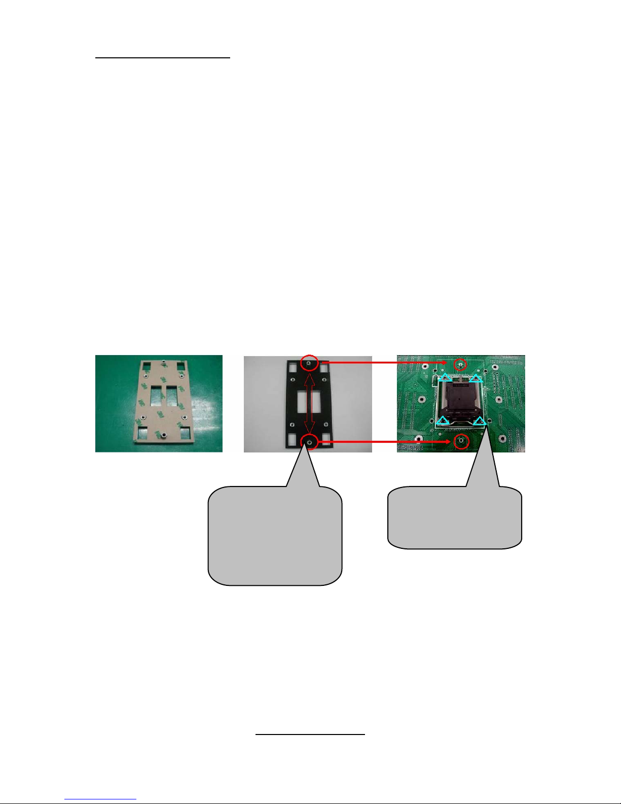
Back plate Assembly
The back plate is mounted on the backside of the motherbo ard and enhances
local stiffness to support shock and vibration loads acting on the heat sink. The
back plate assembly prevents excessive motherboard stress in the area near
the processor. Without a back plat e, excessive stress could cause serious
damage to electrical connections of the processor socket and integrated circuit
packages surrounding the processor. The back plate also serves as a
reinforcement plate for the LGA socket.
While doing the installat ion, be careful in holding the co mponents.
Follow these instructions to install your back plate:
1. Remove the release l iner from the back plate.
2. Align the PEM nuts on the b ack plate to the holes on the reverse side
of the PCB.
3. First, insert the taller upper & lower middle PEM nuts through the
holes of the PCB. The remaining four short e r PEM nuts should
automatically fit the 4 holes on the PCB as shown in the following
pictures.
Let 2 upper &
lower-middle
PEM nuts pass
through the
holes.
4 PEM nuts
should fit 4
holes.
http://www.tyan.com
24
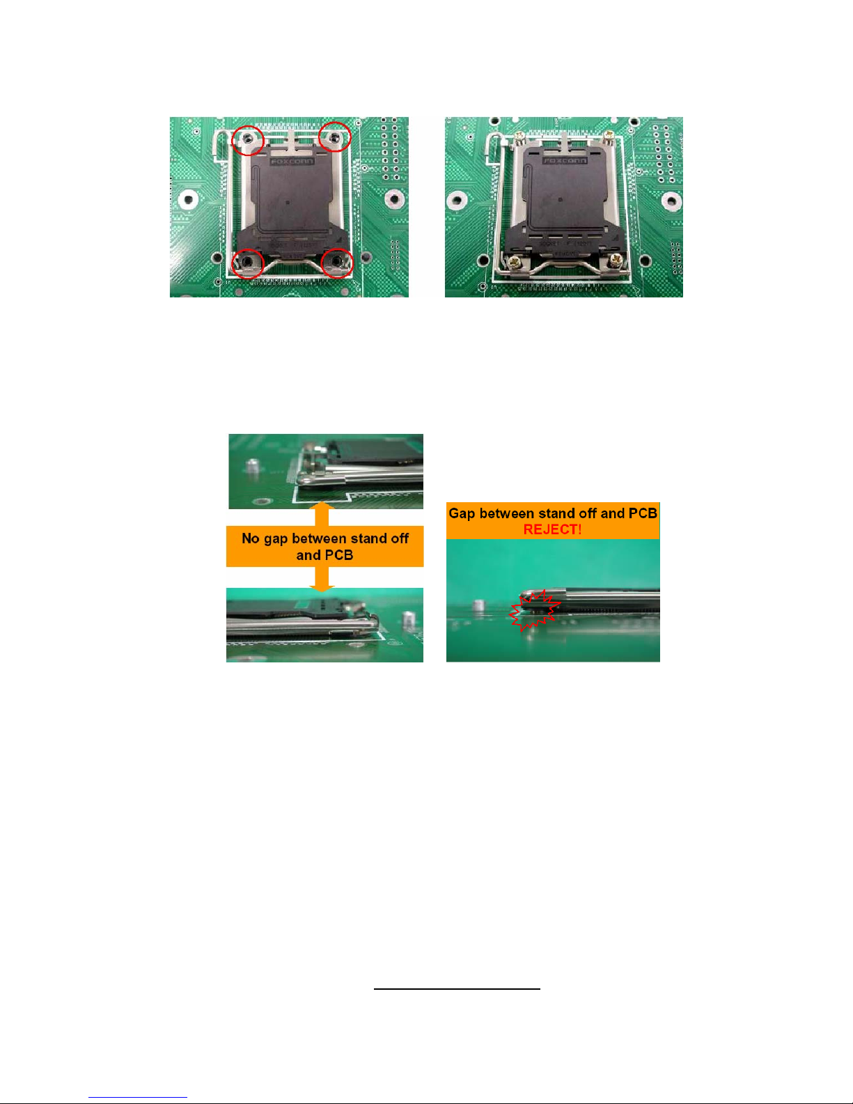
4. Locate four screw holes on socket and screw the socket to the PCB
board.
NOTE: Do not assemble CPU bef ore securing socket with screws.
5. Inspect Socket F assembly to PCB. The Socket F must be tightly
attached onto the PCB. There must NOT be any gap between stand
off the PCB.
 Loading...