

TYAN THUNDER K8SE, Thunder K8SE S2892, S2892 User Manual

http://www.tyan.com
1
Thunder K8SE
///
S2892
Version 1.02
Copyright
Copyright © TYAN Computer Corporation, 2004-2005. All rights reserved. No
part of this manual may be reproduced or translated without prior written
consent from TYAN Computer Corp.
Trademark
All registered and unregistered trademarks and company names contained in
this manual are property of their respective owners including, but not limited to
the following.
TYAN, Taro and Thunder K8SE are trademarks of TYAN Computer Corporation.
AMD, Opteron, and combinations thereof are trademarks of AMD Corporation.
Nvidia and nForce are trademarks of Nvidia Corporation
Microsoft, Windows are trademarks of Microsoft Corporation.
SuSE,is a trademark of SuSE AG.
Linux is a trademark of Linus Torvalds
IBM, PC, AT, and PS/2 are trademarks of IBM Corporation.
Winbond is a trademark of Winbond Electronics Corporation.
Notice
Information contained in this document is furnished by TYAN Computer
Corporation and has been reviewed for accuracy and reliability prior to printing.
TYAN assumes no liability whatsoever, and disclaims any express or implied
warranty, relating to sale and/or use of TYAN products including liability or
warranties relating to fitness for a particular purpose or merchantability. TYAN
retains the right to make changes to product descriptions and/or specifications
at any time, without notice. In no event will TYAN be held liable for any direct or
indirect, incidental or consequential damage, loss of use, loss of data or other
malady resulting from errors or inaccuracies of information contained in this
document.

http://www.tyan.com
2
Table of Contents
Chapter 1: Introduction
1.1 Congratulations Page 3
1.2 Hardware Specifications Page 3
1.3 Software Specifications Page 5
Chapter 2: Board Installation
2.1 Board Image Page 7
2.2 Block Diagram Page 9
2.3 Board Parts, Jumpers and Connectors Page 10
2.4 Installing the Processor(s) Page 20
2.5 Heatsink Retention Frame Installation Page 21
2.6 Thermal Interface Material Page 22
2.7 Heatsink Installation Procedures Page 23
2.8 Tips on Installing Motherboard in Chassis Page 25
2.9 Installing the Memory Page 26
2.10 Attaching Drive Cables Page 29
2.11 Installing Add-In Cards Page 31
2.12 Connecting External Devices Page 32
2.13 Installing the Power Supply Page 33
2.15 Finishing Up Page 34
Chapter 3: BIOS
3.1 BIOS Setup Utility Page 35
3.2 BIOS Menu Bar Page 36
3.3 BIOS Legend Bar Page 36
3.4 Getting Help Page 36
3.5 BIOS Main Menu Page 37
3.6 BIOS Advanced Menu Page 38
3.7 BIOS Memory Menu Page 55
3.8 Security Menu Page 57
3.9 BIOS Boot Menu Page 58
3.10 Power Menu Page 60
3.9 BIOS Exit Menu Page 61
Chapter 4: Diagnostics
4.1 Beep Codes Page 63
4.2 Flash Utility Page 63
4.3 BIOS Post Code Page 64
Glossary
Page 67
Technical Support
Page 73

http://www.tyan.com
3
Chapter 1: Introduction
1.1 - Congratulations
You have purchased one of the most powerful server/work station solutions.
The Thunder K8SE (S2892) is a high-end server/work station mainboard, based
on Nvidia nForce pro2200, Winbond W83627HF Super I/O, Analog Devices,
ADT7463 Hardware Monitoring and AMD-8131
TM
PCI-X Tunnel chipsets.
Designed to support up to two AMD Op teron™ (200 series ) processors and
16GB of DDR400/333 memory, the S2892 is ideal for CPU, memory, and
network intensive applications required in the HPC and clustering applications.
Remember to visit TYAN’s Website at http://www.tyan.com
. There you can find
information on all of TYAN’s products with FAQs, online manuals and BIOS
upgrades.
1.2 - Hardware Specifica tions
Processors
•Two uPGA 940-pin ZIF sockets
•Supports one or two AMD
Opteron
TM
processors
•Integrated 128-bit Dual Channel
DDR memory controller
Chipset
•Nvidia nForce pro2200
•AMD 8131™ PCI-X Tunnel
•Winbond W83627HF Super I/O
•Analog Devices ADT7463
Hardware Monitoring IC
Memory
•128-bit dual channel memory bus
•Total Eight 184-pin 2.6-volt DDR
DIMM sockets (four per CPU)
•Supports up to 16GB Registered
DDR
•Supports ECC type memory
modules
•Supports DDR400, DDR333
Integrated SATAII Controllers
•Two integrated dual port SATA II
controllers
•Four SATA connectors support up
to four drives
•Support up to 3Gb/s
Integrated LAN Controllers
•One Broa dcom
BCM5704 Dual
Port GbE controller
- Two RJ-45 LAN connectors with
LEDs
- Connected to PCI-X Bridge B
- Two front panel LED headers
•One Intel
82551QM 10/100 Mbps
Ethernet controller
- One RJ-45 LAN connector with
LEDs stacked on rear two-USB2.0
ports
- Connected to 32bit/33MHz PCI
2.3 bus
- One front panel LED header

http://www.tyan.com
4
Expansion Slots
•One x16 PCI Express expansion
slot, which can split to two x8
slots through riser card
•One PCI 2.3 compliant 5V tolerant
32bit/33MHz slot
•One x16 PCI Express slot with x4
signals
•Two independent 64-bit PCI-X
buses
- Two 133/100/66 MHz PCI-X slots
from Bridge A
- One 100/66 MHz PCI-X slot from
Bridge B
- One 100/66 MHz max Tyan
TARO SODIMM from Bridge B
Integrated I/O
•One floppy connector
•One parallel port header and two
serial (one connector, one
header)
•Four USB2.0 ports (two rear
connectors & two fr on t panel
headers)
•One 15-pin VGA connector
•PS/2 mouse and keyboard
connectors
System Management
•Total 7 fan headers with
monitoring
- Four 3-pin fan head ers
- Three 4-pin fan headers
•One 2-pin chassis intrusion
header
•Temperature, voltage and fan
monitoring
Integrated Enhanced IDE
Controller
•Two IDE dual-drive ports for up to
four EIDE devices
•Supports for UDMA
133/100/66/33 IDE drives and
ATAPI devices
BIOS
• Phoenix BIOS on 8Mbit LPC
Flash ROM
•PXE via Ethernet, USB device
boot
•SMBIOS 2.3.1, BBS 1.1 compliant
•Headless operation via serial
conso le redirec t
•48-bit LBA support
Intelligent Platform
Management Interface Header
•Tyan Server Management
Daughter card (optional)
supports features listed below
via SMDC header
- Baseboard Management
Controller (BMC)
- Tailored for IPMI
- Supports KCS and BT styles
- Flexible Windows or Linux
management solution
- Supports RMCP and SNMP
protocols
- Supports ASF standard and EMP
- 1
2
C serial multi-master controllers
and UARTs
- Built-in IPMB connector
- Remote power on/off and reset
support (IPMI-over-LAN)
Regulatory
•FCC Class B (Do C)
•European Community CE (DoC)
Integrated Video Controller
•ATI
®
RAGE XLTM PCI contr oller w/
8MB memory

http://www.tyan.com
5
Form Factor
•SSI EEB v3.0 Footprint (12” x 13”,
304.8 x 330.2mm) fits most
Rackmount E-ATX chassis
•EPS 12V/SSI (24 + 8 pin) power
connectors
•Serial (one) and VGA (one)
connectors
•Stacked USB 2.0 (two) with one
RJ45 connectors
•Stacked PS/2 keyboard and
mouse connectors
•Two RJ-45 LAN connecto rs with
LEDs
1.3 - Software Spec ifications
OS (Operating System) Support
Microsoft Windows 2000
Microso ft Wi ndo ws XP
Microsoft Windows Server 2003
SUSE Professional 9.x and SLES 9
RHEL3 Update 4
TYAN reserves the right to add support or discontinue support for any OS with
or without notice.

http://www.tyan.com
6
NOTES:

http://www.tyan.com
7
Chapter 2: Board Installation
Precautions: The Thunder K8SE supports SSI, EPS12V type power supplies
(24pin + 8pin) and will not operate with any other types. For proper power
supply installation procedures see page 34.
DO NOT USE ATX 2.x or ATXGES power supplies as they will damage the
board and void your warranty.
How to install our products right… the first time
The first thing you should do is reading this user’s manual. It contains important
information that will make configuration and setup much easier. Here are some
precaut i ons you should take when installing your motherboard:
(1) Ground yourself properly before removing your motherboard from the
antistatic bag. Unplug the power from your computer power supply and
then touch a safe ly grounded ob j ect to re le as e st atic charge (i .e. po w er
supply case). For the safest conditions, TYAN recommends wearing a
static safety wrist strap.
(2) Hold the motherboard by its edges and do not touch the bottom of the
board, or flex the board in any way.
(3) Avoid touching the motherboard components, IC chips, connectors,
memory modules, and leads.
(4) Place the motherboard on a grounded antistatic surface or on the
antistatic bag that the board was shipped in.
(5) In spe ct the board for damage.
The following pages include details on how to install your motherboard into your
chassis, as well as installing the processor, memory, disk drives and cables.
NOTE
DO NOT APPLY POWER TO THE BOARD IF IT HAS BEEN
DAMAGED
http://www.tyan.com
8
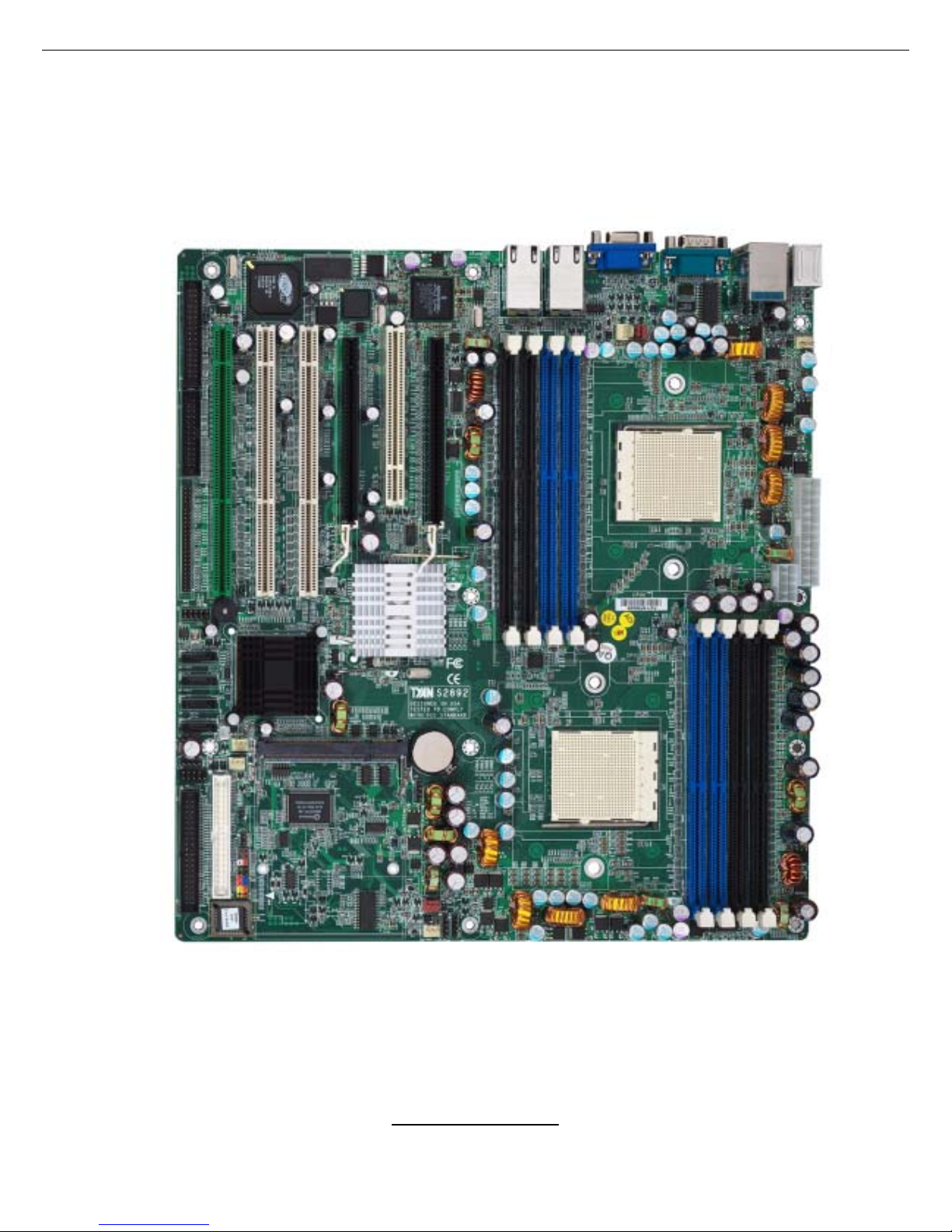
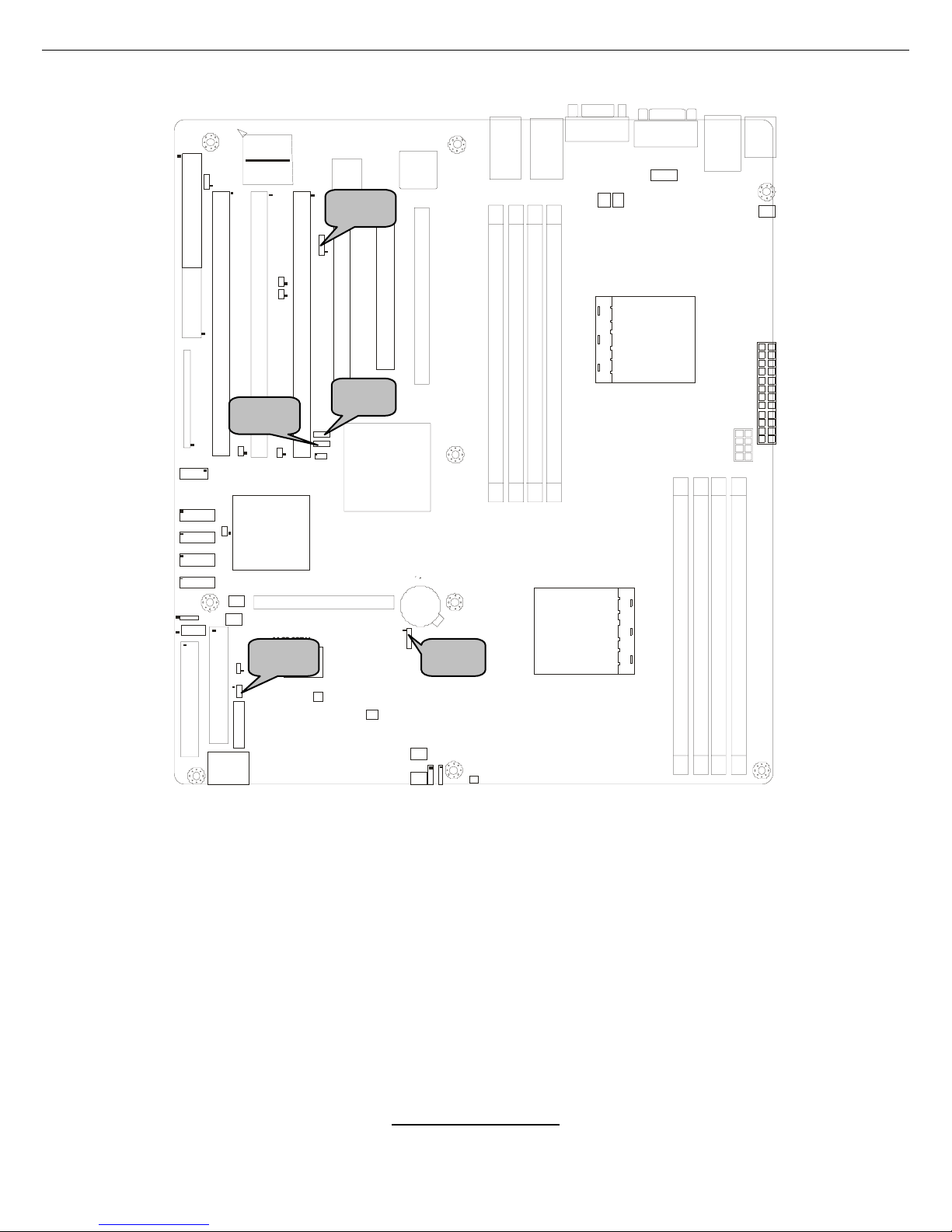
2.1- Board Image
This picture is representative of the latest board revision available at
the time of publishing. The board you receive may or may not look
exactly like the above picture.
The following page includes details on the vital component s of this
motherboard.
http://www.tyan.com
9
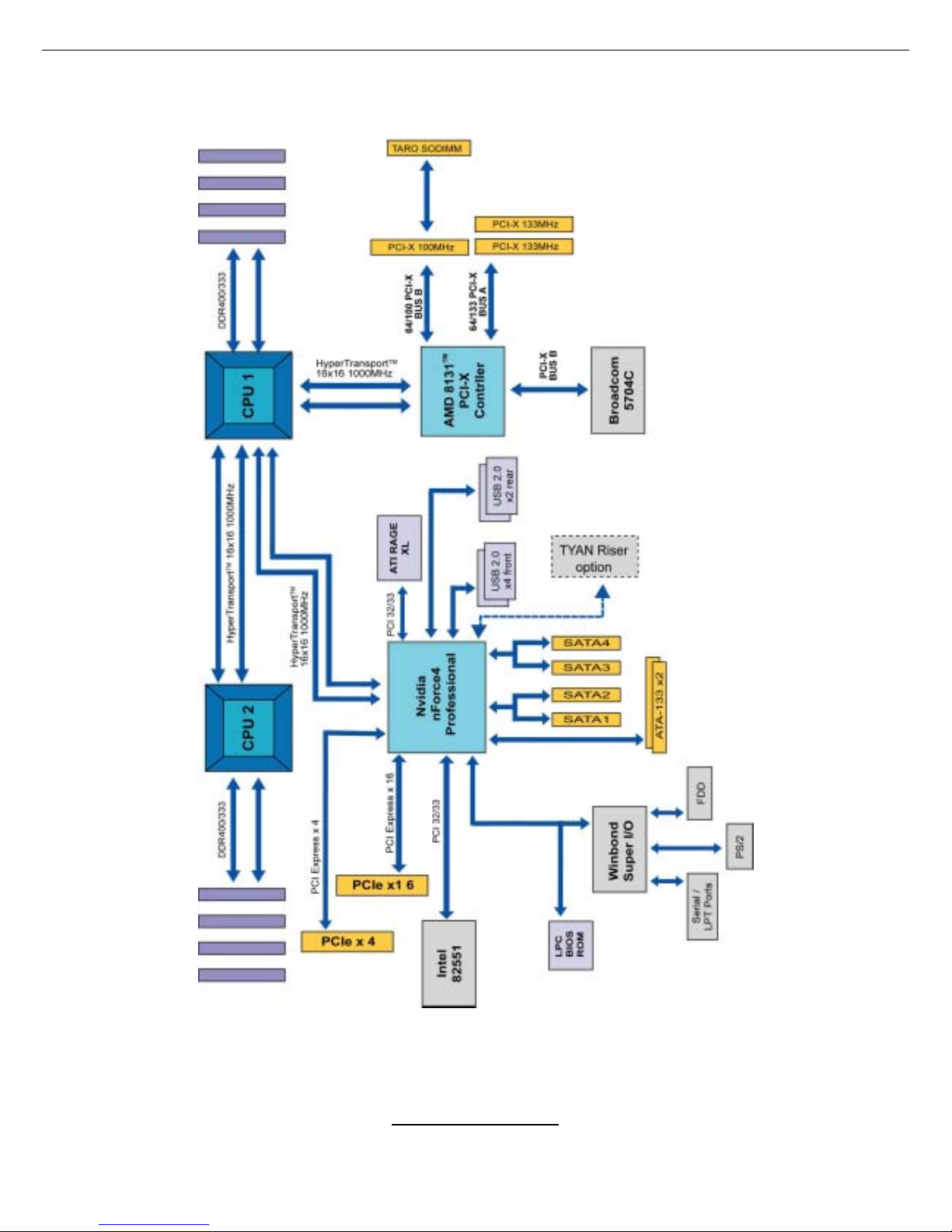
2.2 - Block Diagram
Thunder K8SE (S2892) Block Diagram
http://www.tyan.com
10
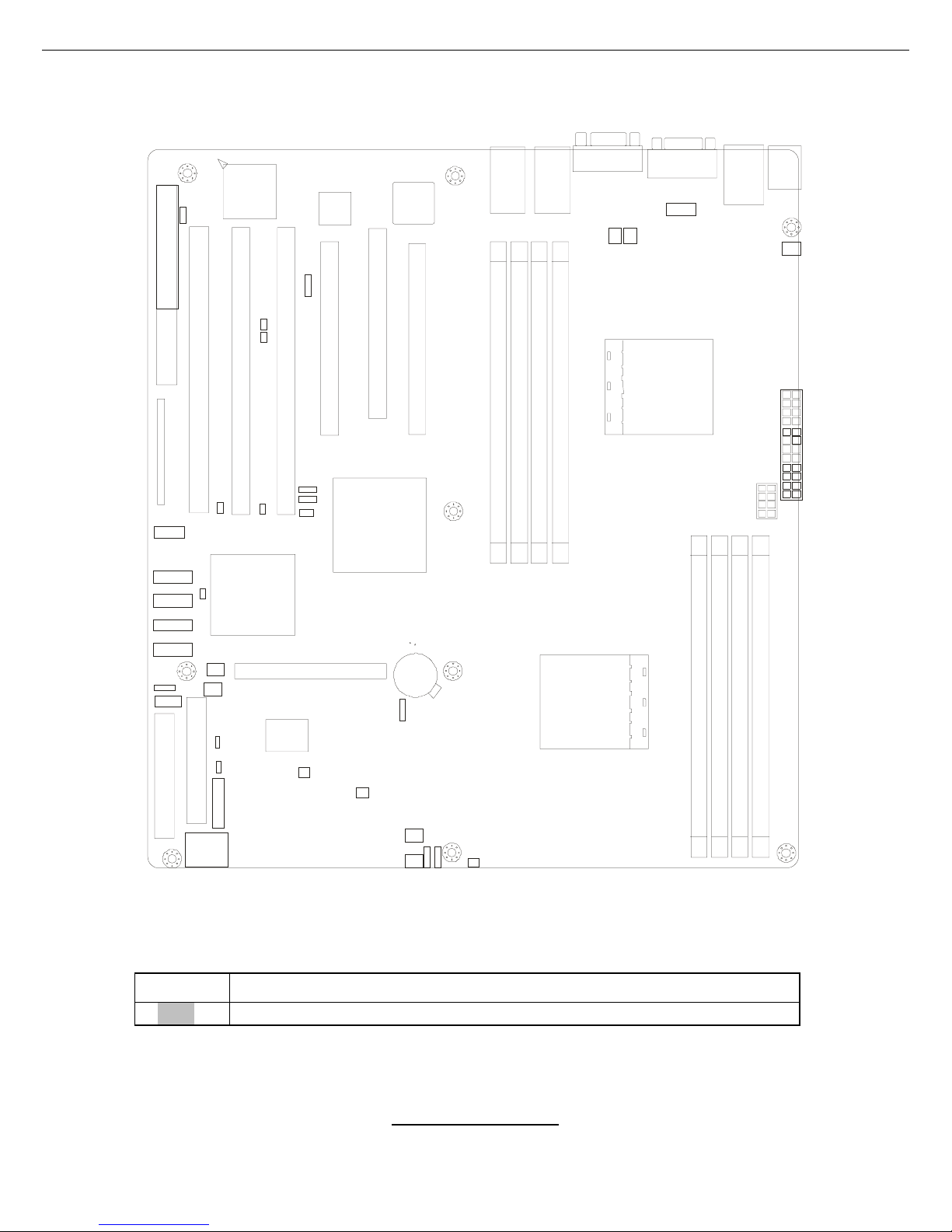
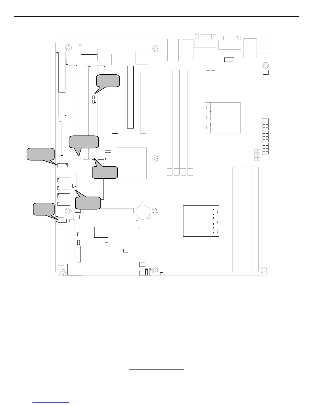
2.3 - Board Parts, Jumpers and Conn ec tors
CPU 2
CPU 1
DIMM A1
DIMM A2
DIMM B1
DIM M B2
DIMM A1DIMM A1
DIMM B2
DIM M B1
DIMM A 2
DIMM A 1
DIMM B2
X16 PCI Express
PCI 32
X4 PCI Express
X16 PCI Express
100/66 PCI-X
133/100 PCI-X133/100 PCI-X
133/100 PCI-X
FDD1
J24
LPT1
J42
J37
J38
J39
J43
J41
J36
J49
J48
J47
J44
IDE1
IDE2
BIOS
Win bond
M83627HF-AW
J50
J53
J51 / 52J
J46
DIM M B2
P1W
PW2
J11
J9
J10
RAGE XL
215R 3LASB 41
J26
J35
Nvidia
Crush K8-0 4
AMD
8131 PCI-X
1
1
1
1
1
1
1
1
1
1
1
1
1
1
1
1
1
1
1
1
1
1
1
1
1
J25
J15
J16
J8
1
J25
J56
1
J1P
J57
J58
J45
1
J14
U10
R3T
R1T
R2T
This diagram is representative of the latest bo ard revision available at the time of
publishing. The board you receive may not look exactly like the above diagram.
Jumper Legend
OPEN - Jumper OFF, without j umper cover
CLOSED – Jumper ON, with jumper cover
http://www.tyan.com
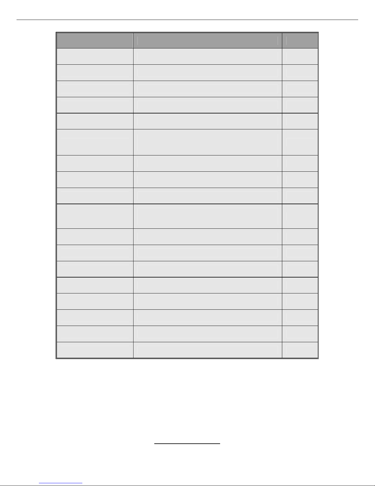
11
Jumper/Connector Function Page
J26 USB Front Panel Header Page 13
J45 COM2 Header Page 13
J15/J56 PCI-X Bridge A Bus Speed Select Jumper Page 13
J25/J36 PCI-X Bridge B Bus Speed Select Jumper Page 13
J8 ATI Onboard VGA Enable/Disable Jumper Page 14
J44/J51/J52
10/100/1000 LAN3/LAN2/LAN1 Front
Panel LED Headers
Page 15
J49 Front Panel Header Page 15
JP1 Clear CMOS Jumper Page 15
J16 PCI-X Bridge A Bus Mode Select Jumper Page 15
J14
Onboard 10/100 Ethernet Enable/Disable
Jumper
Page 17
J48 Chassis Intrusion Connector Page 17
J46 SMBUS Connector Page 17
J57/J58 SMDC/ASF2.0 Select Jumper (Option) Page 17
J53 4-Pin Front Fan Connector Page 19
J50/J9 CPU_Fan Connectors Page 19
J10/J11/J42/J43 3-Pin Chassis Fan Connectors Page 19
J35/J37/J38/J39 Serial ATA RAID Connectors Page 19
J24 SMDC Connector Page 19
http://www.tyan.com
12
CPU 2
CPU 1
DIMM A1
DIMM A2
DIMM B1
DIMM B 2
DIMM A1DIMM A1
DIMM B2
DIMM B1
DIMM A2
DIMM A1
DIMM B2
X16 P C I Ex pr ess
PCI 32
X4 PCI Express
X16 P C I Ex pr ess
100/ 66 PCI-X
133/100 PCI-X133/100 PCI-X
133/100 PCI-X
FDD1
J24
LPT1
J42
J37
J38
J39
J43
J41
J36
J49
J4 8
J47
J44
IDE1
IDE2
BIOS
Winbond
M83627HF-AW
J50
J53
J51/ 52J
J46
DIMM B 2
P1W
PW2
J11
J9
J10
RAG E XL
J26
J35
Nvidia
Cr ush K8 - 0 4
AMD
8131 PCI-X
J25
J15
J16
J8
J25
J56
J1P
J57
J58
J45
J14
U10
R3T
R1T
R2T
J26
J15
J25
JP56
J45
J36
http://www.tyan.com
13
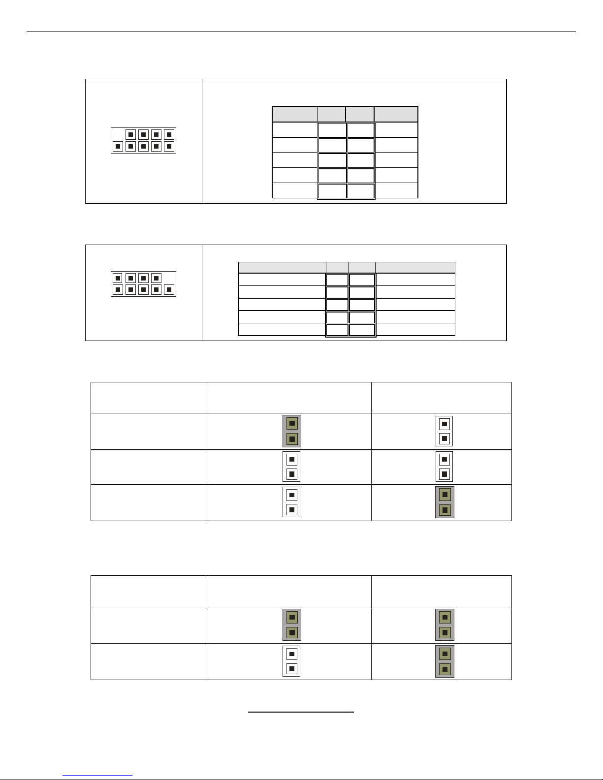
J26: USB Front Panel Header
10 2
9 1
Use this header to connect to front panel USB
connector.
Signal Pin Pin Signal
VCC
1 2
VCC
Data -
3 4
Data -
Data +
5 6
Data +
GND
7 8
GND
KEY
9 10
GND
J45: COM2 Header
2 10
1 9
Use these pin definitions to connect a port to COM2.
Signal Pin Pin Signal
Data Carrier Detect
1 2
Data-Set-Ready
Receive-Data
3 4
Request-to-Send
Transfer-Data
5 6
Clear-to-Send
Data Terminal Ready
7 8
Ring-Indicator
Ground
9 10
NC/KEY
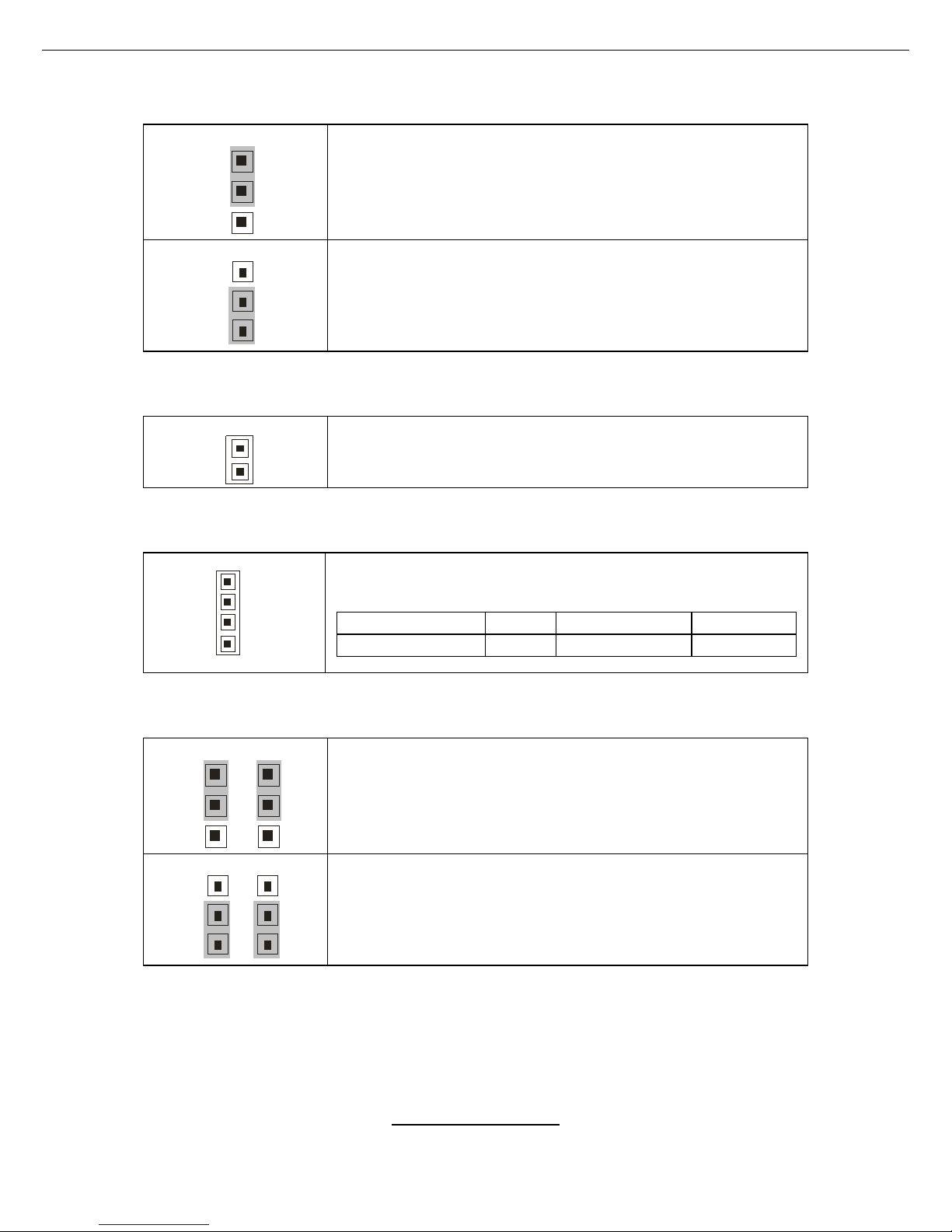
J15/JP56: PCI-X Bridge A Bus Speed Select Jumper
Speed J15 JP56
66MHz
1
1
100MHz
1
1
133MHz
1
1
J25/J36: PCI-X Bridge B Bus Speed Select Jumper
Speed J25 J36
66MHz
1
1
100MHz
1
1
http://www.tyan.com
14
CPU 2
CPU 1
DIM M A1
DIM M A2
DIM M B1
DIMM B2
DIM M A1DIM M A1
DIMM B2
DIM M B1
DIMM A2
DIMM A1
DIMM B2
X16 PCI Express
PCI 32
X4 PCI Express
X16 PCI Express
100/6 6 PC I-X
133/100 PCI-X133/100 PCI-X
133/100 PCI-X
FDD1
J24
LPT1
J42
J37
J3 8
J3 9
J43
J41
J36
J49
J48
J47
J44
IDE1
IDE2
BIOS
Winbond
M83627HF-AW
J50
J53
J51/ 52J
J46
DIMM B2
P1W
PW2
J11
J9
J10
RAGE X L
J26
J3 5
Nvidia
Crush K8-04
AMD
8131 P CI-X
J25
J15
J16
J8
J25
J56
J1P
J57
J58
J45
J14
U10
R3T
R1T
R2T
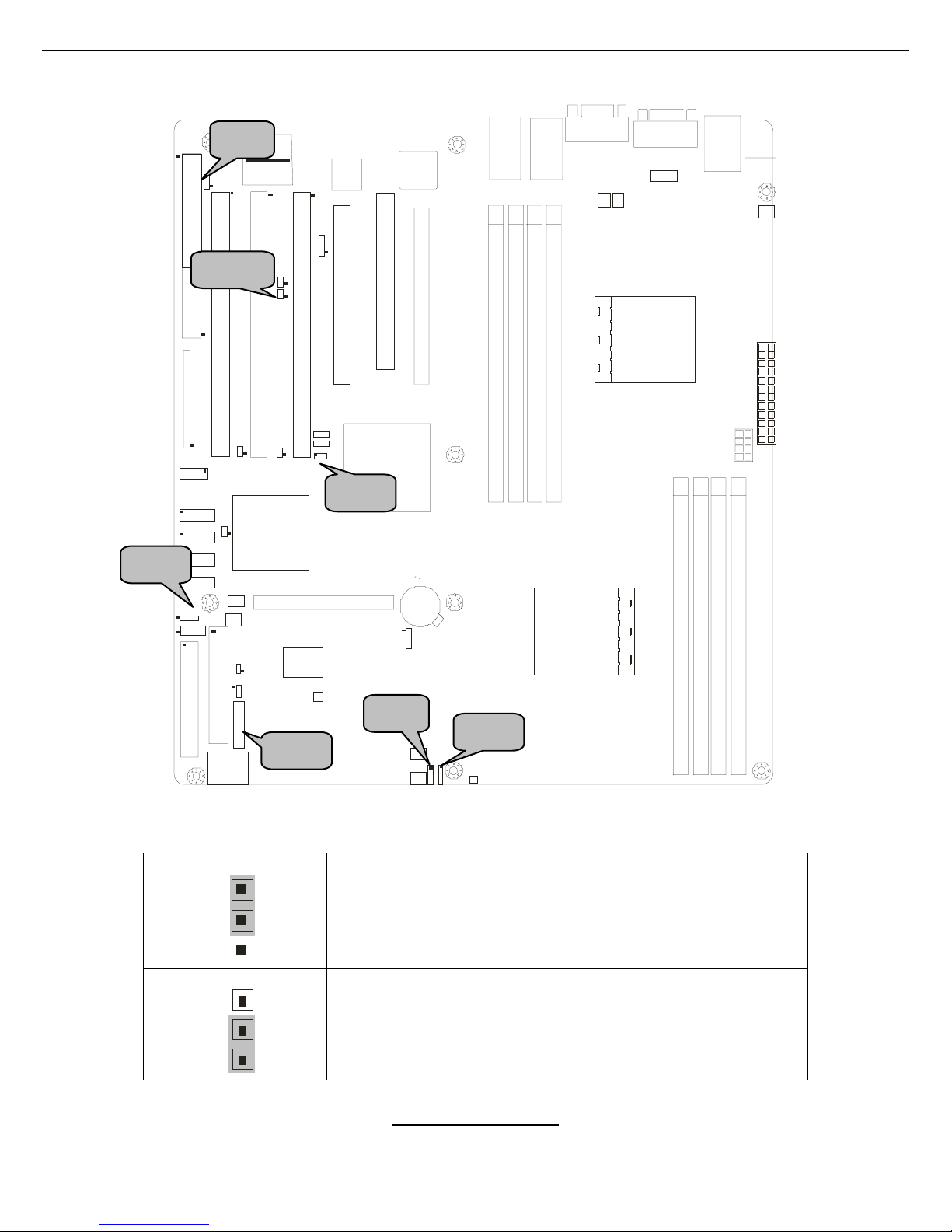
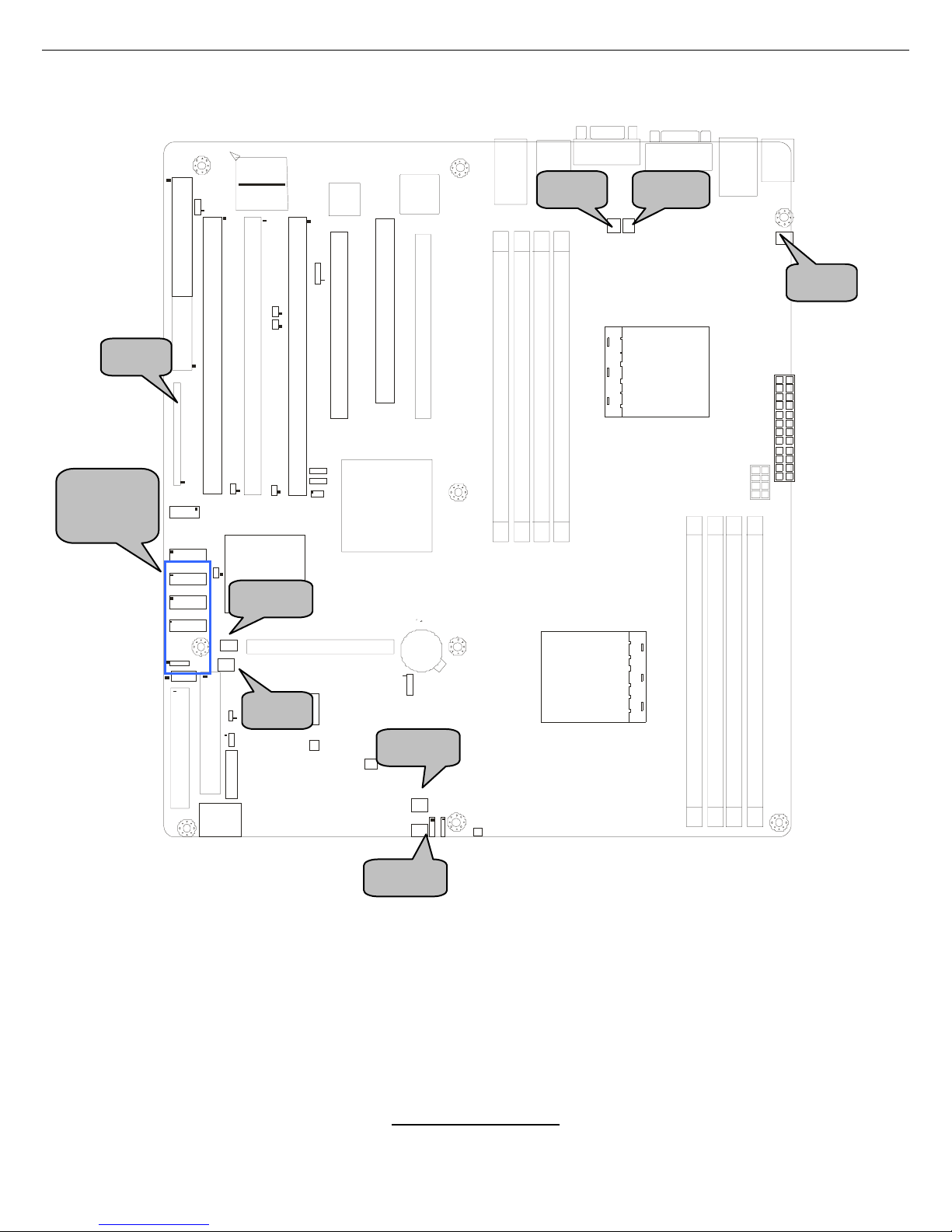
J8: ATI Onboard VGA Enable/Disable Jumper
1
3
(Default)-Enable onboard ATI Rage XL Graphic chip.
1
3
Disable onboard ATI Rage XL Gigabit chip.
J52
J51
J44
J49
J8
JP1
J16
http://www.tyan.com
15
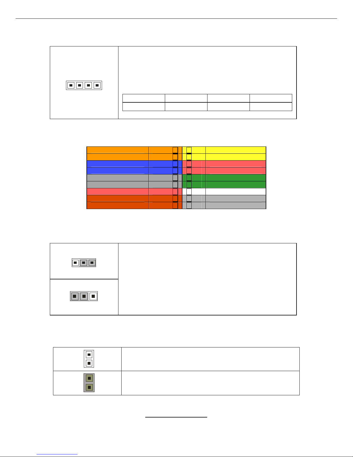
J44/J51/J52: 10/100/1000 LAN3/LAN2/LAN1 Front Panel LED Headers
41
Use these headers to connect with the front panel dual
color LEDs to indicate the speed of LAN1, LAN2 and
LAN3.
J44: LAN3; J51: LAN2; J52: LAN1
Pin 1 Pin 2 Pin 3 Pin 4
Yellow+ Yellow- Green+ Green-
J49: Front Panel Header
JP1: Clear C MOS Jump er
J16: PCI-X Bridge A Bus Mode Select Jumper
1
Open (Default)-Allows PCI slots to operate in PCI-X
mode.
1
Closed-To force PCI slots to operate in PCI compatible
mode. Close this jumper if the card you are using does
not support PCI-X.
HDDLED+ 1 2 PWR LED+
HDDLED- 3 4 PWR LED-
GND 5 6 PWR SW
Reset SW+ 7 8 GND
+5V 9 10 NC
IRRX 11 12 Speaker+
GND 13 14 NC (KE Y)
IRTX 15 16 Buzzer+
NC 17 18 Speaker-/Buzzer-
31
(Clear)
3
1
(Default)
You can reset CMOS settings by using this jumper if
you have lost your system/setup password or need to
clear system BIOS setting.
Power off system and disconnect both power
connectors from the motherboard before clearing
CMOS. Reconnect power and power on system after
done.
http://www.tyan.com
16
CPU 2
CPU 1
DIM M A1
DIM M A2
DIM M B1
DIMM B2
DIM M A1DIM M A1
DIMM B2
DIM M B1
DIMM A2
DIMM A1
DIMM B2
X16 PCI Express
PCI 32
X4 PCI Express
X16 PCI Express
100/6 6 PC I-X
133/100 PCI-X133/100 PCI-X
133/100 PCI-X
FDD1
J24
LPT1
J42
J37
J3 8
J3 9
J43
J41
J36
J49
J48
J47
J44
IDE1
IDE2
BIOS
Winbond
M83627HF-AW
J50
J53
J51/ 52J
J46
DIMM B2
P1W
PW2
J11
J9
J10
RAGE X L
J26
J3 5
Nvidia
Crush K8-04
AMD
8131 P CI-X
J25
J15
J16
J8
J25
J56
J1P
J57
J58
J45
J14
U10
R3T
R1T
R2T
J14
J48 J46
J57
J58
http://www.tyan.com
17
J14: Onboard 10/100 Ethernet Enable/Disable Jumper
1
3
(Default)-To enable onboard 10/100 Ethernet.
1
3
To disable onboard 10/100 Ethernet.
J48: Chassis Intrusion Connector
1
Pin 1: Intrusion detection. Pin 2: GND.
For use with chassis that support this feature.
J46: SMBUS Connector
4
1
Use this connector to connect external SMBUS
devices.
Pin 1 Pin 2 Pin 3 Pin 4
SMBUS_DATA GND SMBUS_CLK NC
J57/J58 : SMDC/ASF2.0 Se lect Jumper (Optio n)
J57 J58
1
3
1
3
Support SMD C card
J57 J58
1
3
1
3
Support ASF 2.0
http://www.tyan.com
18
CPU 2
CPU 1
DIMM A1
DIMM A2
DIMM B1
DIMM B2
DIMM A1DIMM A1
DIMM B2
DIMM B1
DIMM A2
DIMM A1
DIMM B2
X16 P C I Expr ess
PCI 32
X4 PCI Express
X16 P C I Expr ess
100/66 PCI-X
133/100 PCI-X133/100 PCI-X
133/100 PCI-X
FDD1
J24
LPT1
J42
J37
J38
J39
J43
J41
J36
J49
J48
J47
J44
IDE1
IDE2
BIOS
Winbond
M83627HF-AW
J50
J53
J51/ 52J
J46
DIMM B2
P1W
PW2
J11
J9
J10
RAG E XL
J26
J35
Nvidia
Cr ush K8 - 0 4
AMD
8131 PCI-X
J25
J15
J16
J8
J25
J56
J1P
J57
J58
J45
J14
U10
R3T
R1T
R2T
J50
J53
J9 J10
J35/J37
J38/J39
J43
J42
J11
J24
http://www.tyan.com
19
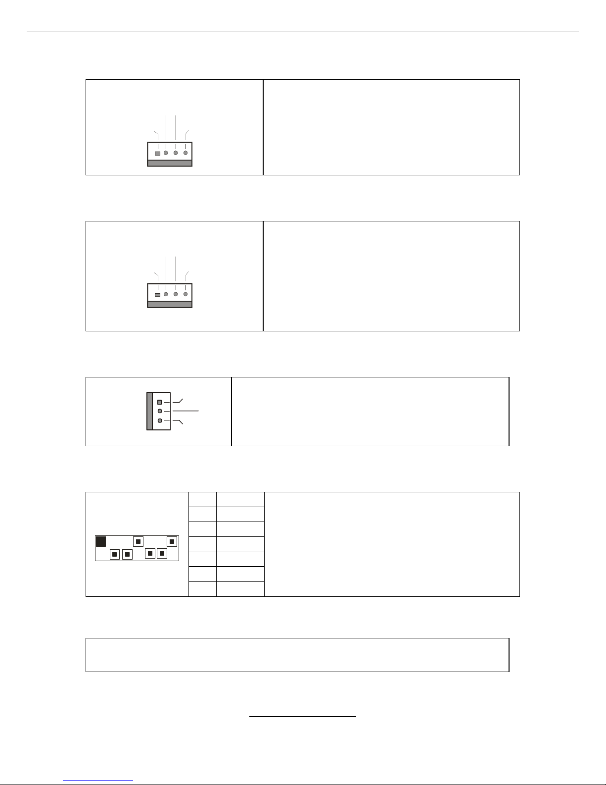
J53: 4-Pin Front Fan Connector
+12 V
Speed Contro l 2
Spe ed Control
Ta c ho met e r
Use this header to connect the chassis
cooling fan to your motherboard to keep the
system stable and reliable.
This connector supports the tachometer
monitoring and auto fan speed control.
J50/J9: CPU_Fan Connectors
+12 V
Speed Contro l 2
Spe ed Control
Ta c ho met e r
Use these hea der s to connect the processor
cooling fans to your motherboard to keep the
system stable and reliable.
J50: CPUFAN1, J9: CPUFAN2
These connectors support the tachometer
monitoring and auto fan speed control.
J10/J11/J42/J43: 3-Pin Chassis Fan Connectors
+12V
GND
NC
Use these headers to connect the chassis cooling
fan to your motherboard to keep the system at
optimum performance levels.
J35, J37, J38, J39: Serial ATA RAID Connectors
7 GND
6 RXP
5 RXN
4 GND
3 TXN
2 TXP
1 7
1 GND
Connects to the Serial ATA ready drive s via
the Serial ATA cable
You may use any two of the four Serial ATA
ports to have the support of RAID 0 and 1
through the on board ICH6R south bridge chip.
J24: SMDC Connector
For connection with Tyan Server Management Daughter Card (SMDC).
The SMDC connector supports
http://www.tyan.com
20
2.4 - Installing the Processor(s)
Your brand new Thunder K8SE supports the latest 64-bit processor technology
from AMD. Only AMD Opteron
™
processor 200 series are certified and
supported with this motherboard.
Check our website for latest processor support. http://www.tyan.com
NOTE
If using a single processor, it MUST be installed in socket
CPU1. When using a single processor only CPU1 memory
banks are addressable.
TYAN is not liable for damage as a result of operating an unsupported
configuration.
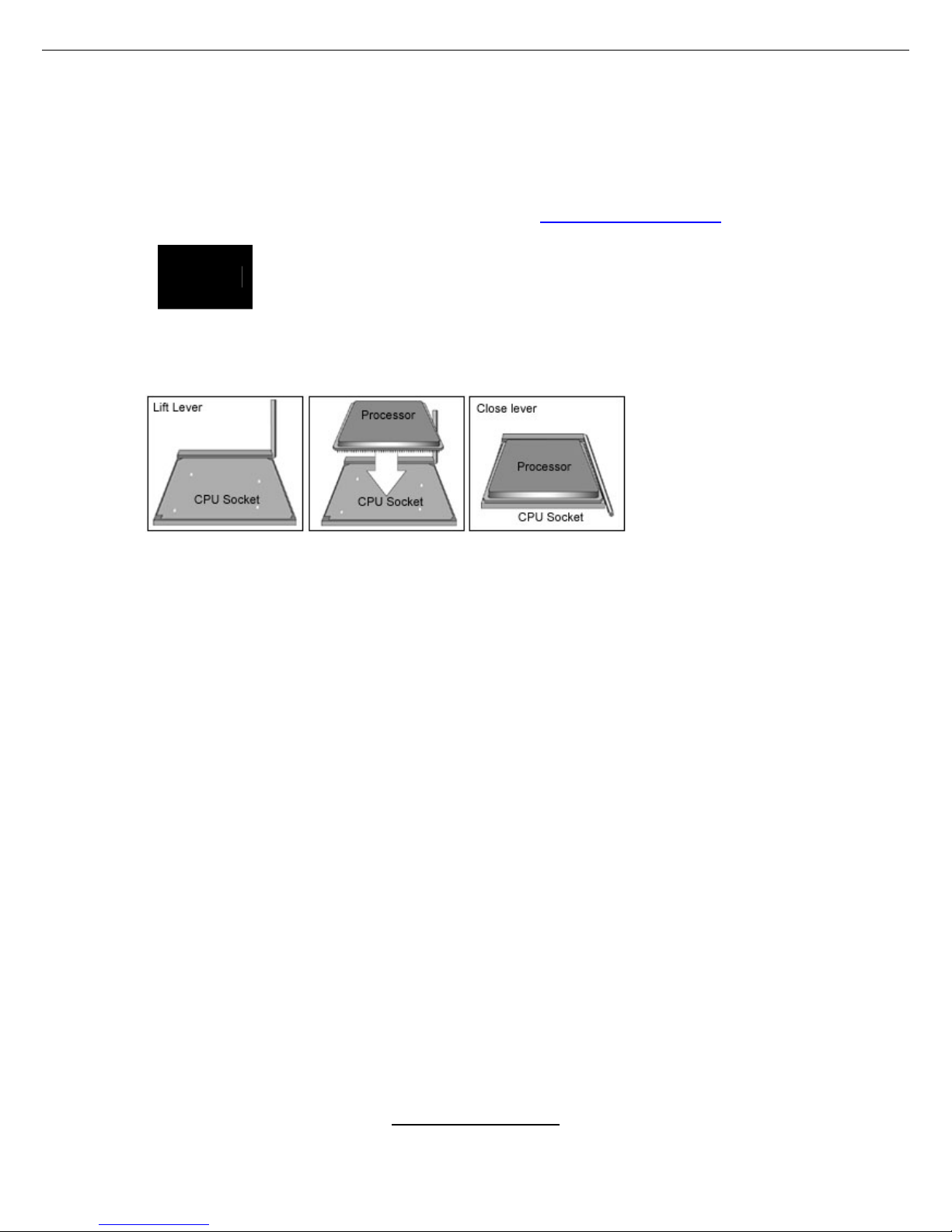
The diagram is provided as a visual guide to help you install socket processors
and may not be an exact representation of the processors you have.
Step 1: Lift the lever on the socket until it is approximately 90
o
or as far back as
possible to the socket.
Step 2: Align the processor with the socket. There are keyed pins underneath
the processor to ensure that the processor’s installed correctly.
Step 3: Seat the processor firmly into the socket by gently pressing down until
the processor sits flush with the socket.
Step 4: Place the socket lever back down until it locks into place. The
installation is finished.
Repeat these steps for the second processor if you are using two processors.
Take care when installing processors as they have very fragile connector pins
below the processor and can bend and break if inserted improperly.
http://www.tyan.com
21
2.5 - Heatsink Retention Frame Installation
After you are done installing the processor(s), you should proceed to installing
the retention frame and heatsink. The CPU heatsink will ensure that the
processors do not overheat and continue to operate at maximum performance
for as long as you own them. Overheated processors are also dangerous to the
motherboard.
The backplate assembly prevents excessive motherboard flex ing in the area
near the processor and provides a base for the installation of the heatsink
retention bracket and heatsink.
Because there are many different types of heatsinks available from many
different manufacturers, a lot of them have their own method of installation. For
the safest method of installation and information on choosing the appropriate
heatsink, use heatsinks validated by AMD. Please refer to AMD’s website at
www.amd.com
.
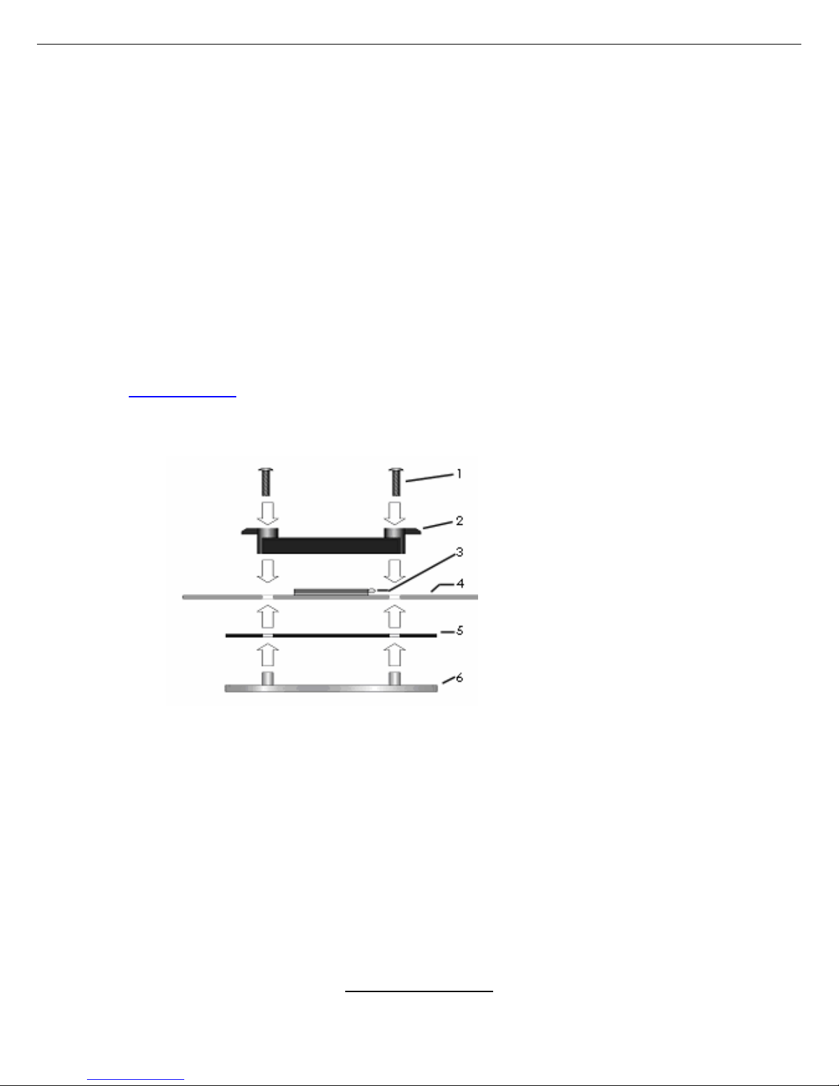
The following diagram will illustrate how to install the most common CPU back
plates:
1. Mounting screws
2. Heatsink retention frame
3. CPU socket
4. Motherboard PCB
5. Adhesive insulator
material
6. Backplate assembly
NOTE: Please see next
section for specific
instructions on how to install
mounting bracket.
http://www.tyan.com
22
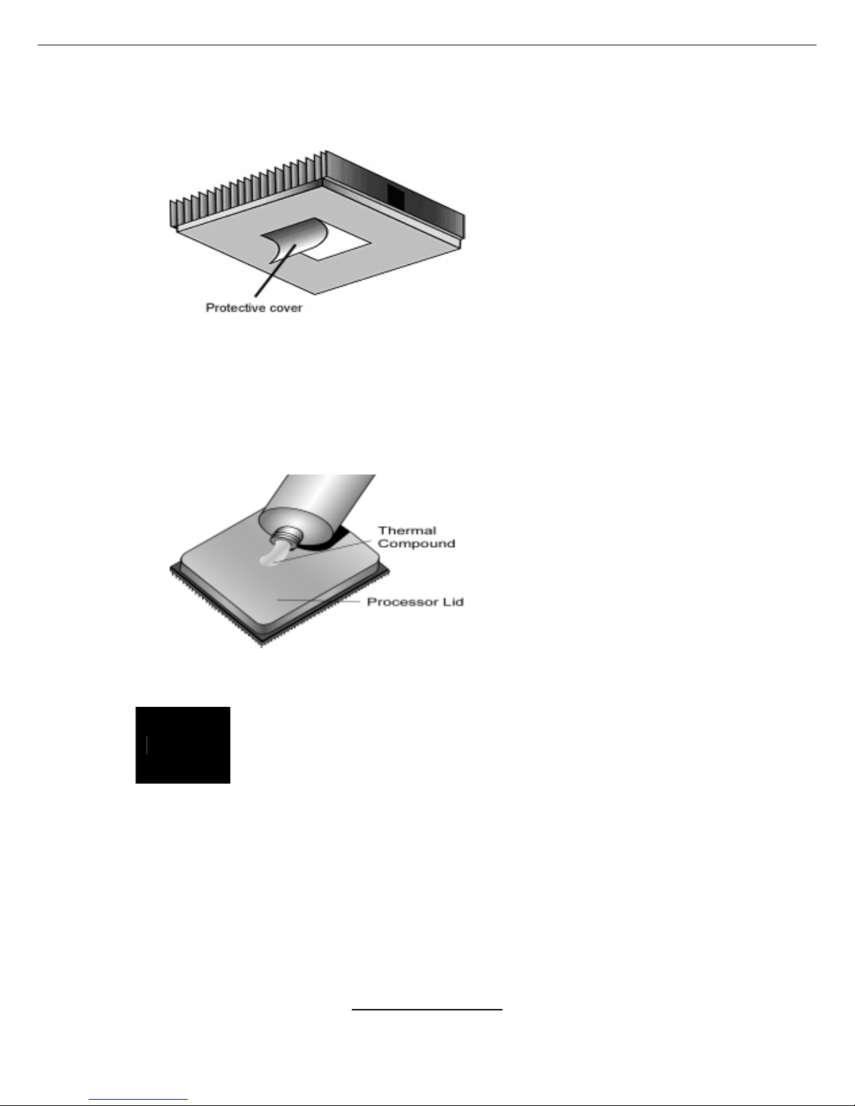
2.6 - Thermal Interface Material
There are two types of
thermal interface materials
designed for use with the
AMD Opteron processor.
The most common material
comes as a small pad
attached to the heatsink at
the time of purchase. There
should be a protective cover
over the material. Take care
not to touch this material.
Simply remove the protective
cover and place the heatsink
on the processor.
The second type of interface
material is usually packaged
separately. It is commonly
referred to as ‘thermal
compound’. Simply apply a
thin layer on to the CPU lid
(applying too much will
actually reduce the cooling).
NOTE
Always check with the manufacturer of the heatsink &
processor to ensure the Thermal Interface material is
compatible with the processor & meets the manufacturer’s
warranty requirements
http://www.tyan.com
23
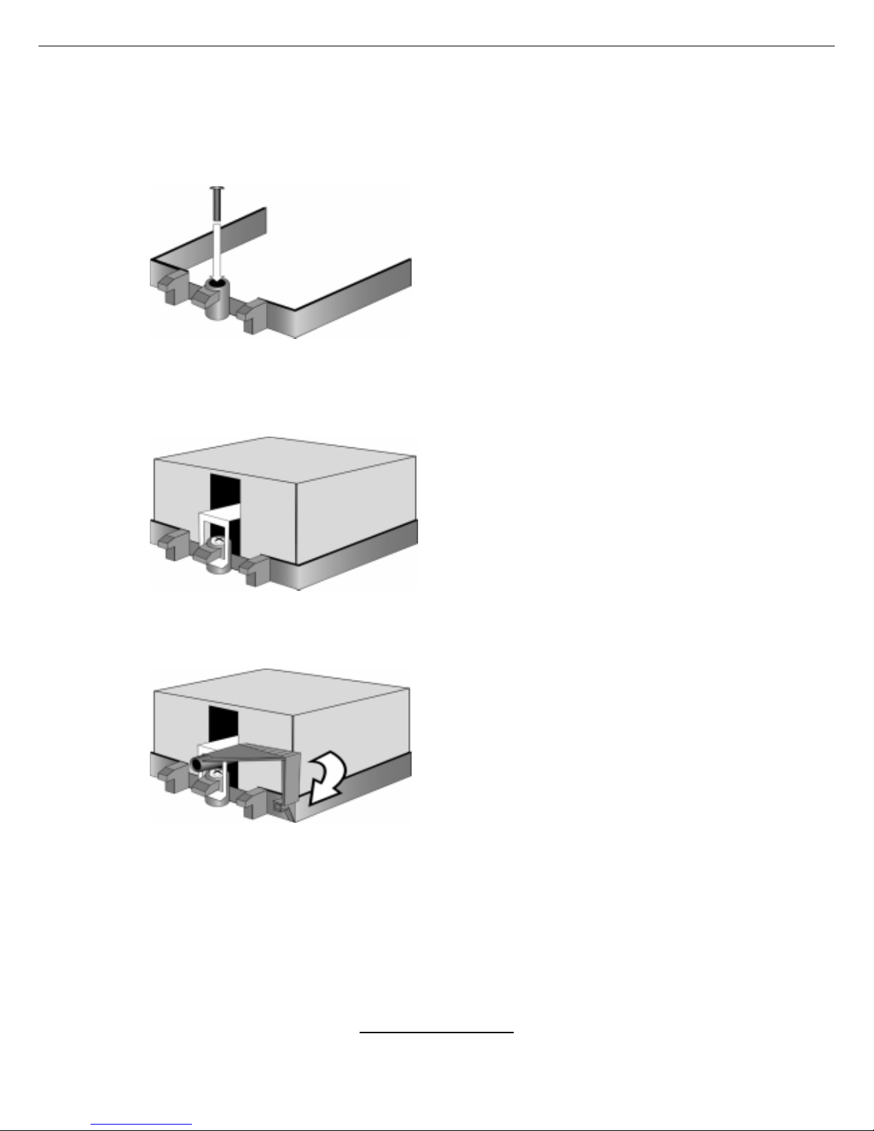
2.7 - Heatsink Installation Procedures
Type A: CAM LEVER (TYPE) INSTALLATION
1. After placing backplate and
interface ma t er i a l un der moth e r b oar d
place heatsink retention frame on top
of motherboard. Align plastic retention
bracket screw holes with CPU backplate standoffs.
Tighten screws to secure plastic
retention bracket. Repeat for the other
side. DO NOT OVER TIGHTEN.
2. After tightening screw s secu re
metal clip to plastic retention bracket
center t a b. Repeat for the other side
of heatsink.
3. After securing meta l c lip to plastic
retention bracket center tab, push
down on plastic clip to lock plastic cl ip
to side tab.
 Loading...