

TYAN Tiger K8W S2875, Tiger K8W, S2875 User Manual

1
http://www.TYAN.com
Tiger K8W
///
S2875
Revision 1.00
Copyright © TYAN Computer Corporation, 2001-2003. All rights reserved. No part of this
manual may be reproduced or translated without prior written consent from TYAN
Computer Corp.
All registered and unregistered trademarks and company names contained in this manual
are property of their respective owners including, but not limited to the following.
TYAN, Tiger K8W are trademarks of TYAN Computer Corporation.
AMD, Opteron, and combinations thereof are trademarks of AMD Corporation.
AMI, AMIBIOS8 are trademarks of American Megatrends Inc.
Microsoft, Windows are trademarks of Microsoft Corporation.
SuSE,is a trademark of SuSE AG.
Linux is a trademark of Linus Torvalds
IBM, PC, AT, and PS/2 are trademarks of IBM Corporation.
Winbond is a trademark of Winbond Electronics Corporation.
Broadcom® is a trademark of Broadcom Corporation and/or its subsidiaries
ATI and Rage XL are trademarks of ATI Corporation
Silicon Image is a trademark of Silicon Image, Inc.
Information contained in this document is furnished by TYAN Computer Corporation and
has been reviewed for accuracy and reliability prior to printing. TYAN assumes no liability
whatsoever, and disclaims any express or implied warranty, relating to sale and/or use of
TYAN products including liability or warranties relating to fitness for a particular purpose
or merchantability. TYAN retains the right to make changes to product descriptions and/or
specifications at any time, without notice. In no event will TYAN be held liable for any
direct or indirect, incidental or consequential damage, loss of use, loss of data or other
malady resulting from errors or inaccuracies of information contained in this document.

http://www.TYAN.com
2
Table of Contents
Before you begin… Page 4
Chapter 1: Introduction
Congratulations Page 5
Hardware Specifications Page 5
Software Specifications Page 6
Chapter 2: Board Installation
2.00 Board Image Page 8
2.01 Block Diagram Page 9
2.02 Board Parts, Jumpers and Connectors Page 10
2.03 Chassis Intrusion Connector (J7) Page 12
2.04 Front Panel Connector (J8) Page 12
2.05 Clear CMOS Jumper (J9) Page 13
2.06 USB1.1 Connector Header (J12) Page 13
2.07 USB2.0 Connector Header (J15) Page 14
2.08 SATA Connectors (J22 / J21 / J20 / J14) Page 14
2.09 Onboard Gigabit Ethernet LAN Jumper (J26) Page 15
2.10 IEEE 1394a Header (J32 / J40) Page 15
2.11 Game Port Header (J34) Page 16
2.12 Aux_in Line_in Connector (J35) Page 16
2.13 CD Audio_in Connector (J36) Page 17
2.14 Front Panel Audio Header (J38) Page 17
2.15 CPU_1 Fan Connector (P1_FAN) Page 17
2.16 CPU_2 Fan Connector (P2_FAN) Page 18
2.17 FAN 1 Chassis Fan Connector (J2) Page 18
2.18 FAN 2 Chassis Fan Connector (J3) Page 18
2.19 FAN 3 Chassis Fan Connector (J6) Page 19
2.20 FAN 4 Chassis Fan Connector (J4) Page 19
2.21 OEM Reserved Connectors and Jumpers Page 19
2.22 POST (Power-On-Self-Test) Code LED Page 19
2.23 Installing the Processor(s) Page 20
2.24 Heatsink Retention Frame Installation Page 21
2.25 Thermal Interface Material Page 22
2.26 Heatsink Installation Procedures Page 23
2.27 Finishing Installing Heatsink Page 24
2.28 Tips on Installing Motherboard in Chassis Page 25
2.29 Installing the Memory Page 26
2.30 Attaching Drive Cables Page 28
2.31 Installing Add-In Cards Page 30
2.32 PCI Riser Cards Supported on S2875 K8W Page 31
2.33 Connecting External Devices Page 31
2.34 Installing the Power Supply Page 32
2.35 Finishing Up Page 32
Chapter 3: BIOS
3.00 BIOS Setup Utility Page 33
3.01 BIOS Menu Bar Page 34
3.02 BIOS Legend Bar Page 34
3.03 BIOS Main Menu Page 35
3.04 BIOS Advanced Menu Page 36
3.05 BIOS PCI/PnP Menu Page 48
3.06 BIOS Boot Menu Page 50
3.07 BIOS Security Menu Page 54

http://www.TYAN.com
3
3.08 BIOS Chipset Setting Menu Page 55
3.09 BIOS Power Menu Page 61
3.10 BIOS Exit Menu Page 62
Chapter 4: Diagnostics Page 63
Appendix I: Glossary Page 64
Appendix II: BIOS POST Code Page 66
Technical Support Page 71
http://www.TYAN.com
4
Before you begin…
Check the box contents!
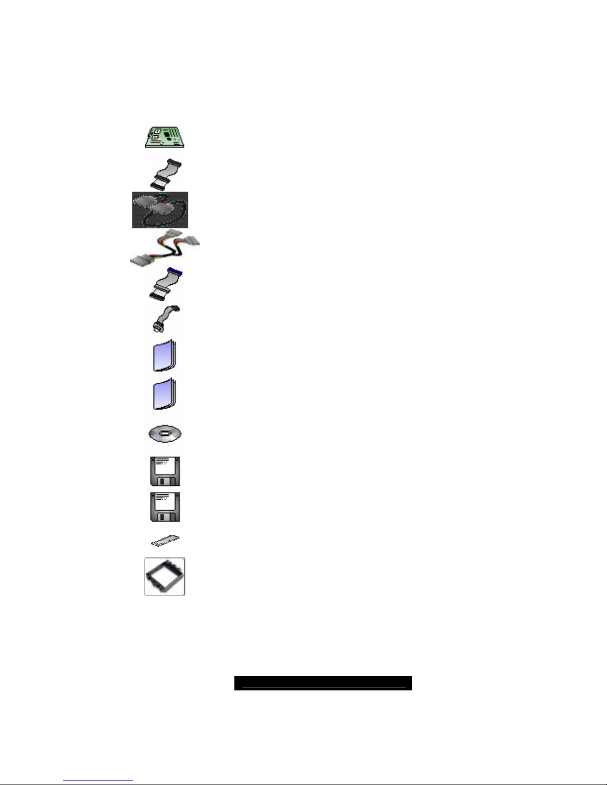
The retail motherboard package should contain the following:
1x Tiger K8W motherboard
1x 34-Pin floppy drive cable
4 x SATA cable
2 x SATA Drive Power Adapter
1 x Ultra-DMA-100/66 IDE cable
1 x Game Port Cable
1 x Tiger K8W user’s manual
1 x Tiger K8W Quick Reference guide
1 x TYAN driver CD
1 x Silicon Image SiI3114 SATA RAID driver diskette
1 x Silicon Image SiI3114 SATA Link driver diskette
1 x I/O shield
2 x CPU Retention Frame
If any of these items are missing, please contact your vendor/dealer for replacement
before continuing with the installation process.

http://www.TYAN.com
5
Chapter 1: Introduction
Congratulations
You are now the owner of the ideal solution for rackmount servers, large computer
clusters, or pedestal server needs. The Tyan Tiger K8W features support for Dual AMD
Opteron processor(s), two channel Gigabit Ethernet, one 10/100 Ethernet and Serial ATA
(SATA).
Remember to visit TYAN’s Website at http://www.TYAN.com. There you can find
information on all of TYAN’s products with FAQs, online manuals and BIOS upgrades.
Hardware Specifications
Processor
Dual µPGA 940-pin ZIF sockets
Supports up to two AMD Opteron™
processors
Onboard VRM, 4-phase PWM
128-bit DDR dual-channel memory
controller integrated in CPU
Chipset
AMD-8151™ HyperTransport™ AGP3.0
Tunnel
AMD-8111™ HyperTransport™ I/O Hub
Winbond W83627HF Super I/O chip
Memory
128-bit DDR dual-channel memory
bus
Total four 184-pin 2.5-Volt DDR DIMM
sockets supports up to 8GB
Supports ECC/Non-ECC type memory
modules
Supports PC2700, PC2100 and
PC1600 Registered DDR
Expansion Slots
One 1.5V AGP 8X/4X slot
Five 32bit/33MHz(5V) PCI slots
Integrated SATA Controller
Silicon Image SiI3114 SATA RAID
Supports SATA 1.0 Specification
Supports 4 channel SATA port for up
to four SATA devices
Supports RAID 0, 1, 0+1
Connected to legacy 32-bit 33MHz
PCI bus
Integrated PCI IDE
Dual channel master mode support up
to four IDE devices
Supports for Ultra ATA/133/100/66
IDE drives and ATAPI compliant
devices
Back Panel I/O Ports
Stacked PS/2 Mouse & Keyboard
ports
Stacked 2 USB 2.0 ports
Two 9-pin UART Serial port
One 25-pin SPP/ECP/EPP parallel
port
One RJ45 10/100/1000 Base-T port
w/ activity LED
Three audio jacks (Mic. In/Linein/Line-out)
Integrated I/O Interface
One floppy connector for up to two
drives
Two USB 2.0 ports
CD-in/Aux-in connectors
2 x 5 pin header for front panel audio
connector
One IRDA connector
Power/IDE LED connectors
Six 3-pin headers for CPU/Chassis
Fans
System Management
Winbond W83627 HF w/ hardware
monitoring function
Six 3-pin Fan headers(three w/
tachometer monitoring)
Temperature and voltage monitoring

http://www.TYAN.com
6
Integrated Audio
Realtek ALC655
6-channel AC ’97 audio CODEC
Line-In/Line-Out/Mic-In audio jacks
CD-in/Aux-in connector
Integrated LAN Controllers
One Giga-bit LAN controller
Intel 82541EI GbE LAN controller
Operating at 32bit/33MHz PCI bus
Power
On board VRM, 4-phase PWM
ATX 12V & EPS12V universal power
connectors
4-pin auxiliary power connector
Port 80 code display LED
BIOS
AMI® BIOS 8.0 on 4Mbit LPC Flash
ROM
Supports APM 1.2 & ACPI 1.0
PnP, DMI2.0, WfM2.0 Power
Management
Power Management S1, S4 and S5
support
Form Factor
6-layer PCB
ATX footprint
12.0” x 9.8”(305mm x 250mm)
Regulatory
FCC Class B (Declaration of
Conformity)
European Community CE
(Declaration of Conformity)
Software Specifications
OS (Operating System) Support
Microsoft Windows NT 4 Service Pack 6A
Microsoft Windows 2000
Microsoft Windows XP
Microsoft Windows Server 2003
SuSE Server 8.0 for AMD-64
Red Hat 7.3, 8.0, and 9.0
Other distributions of Linux pending validation
TYAN reserves the right to add support or discontinue support for any OS with or without
notice.

http://www.TYAN.com
7
Chapter 2: Board Installation
Precaution: The Tiger K8W supports EPS12V power supplies (24-pin/8-pin) and will not
operate with any other types.
DO NOT USE ATX 2.x, ATX12V or ATXGES power supplies as they will damage the
board and void your warranty.
How to install our products right… the first time
The first thing you should do is read this user’s manual. It contains important information
that will make configuration and setup much easier. Here are some precautions you
should take when installing your motherboard:
(1) Ground yourself properly before removing your motherboard from the antistatic
bag. Unplug the power from your computer power supply and then touch a
safely grounded object to release static charge (i.e. power supply case). For the
safest conditions, TYAN recommends wearing a static safety wrist strap.
(2) Hold the motherboard by its edges and do not touch the bottom of the board, or
flex the board in any way.
(3) Avoid touching the motherboard components, IC chips, connectors, memory
modules, and leads.
(4) Place the motherboard on a grounded antistatic surface or on the antistatic bag
that the board was shipped in.
(5) Inspect the board for damage.
The following pages include details on how to install your motherboard into your chassis,
as well as installing the processor, memory, disk drives and cables.
NOTE DO NOT APPLY POWER TO THE BOARD IF IT HAS BEEN DAMAGED
http://www.TYAN.com
8
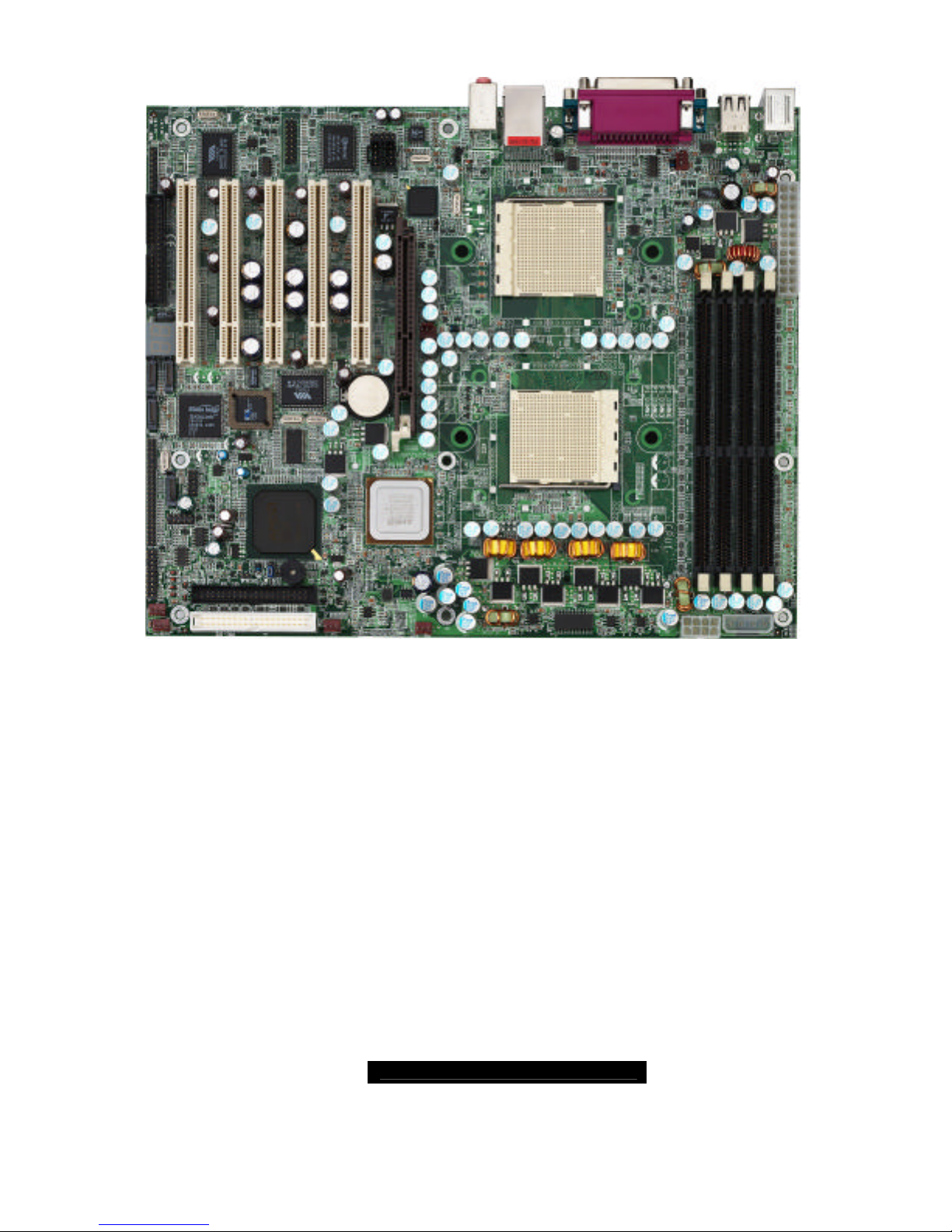
2.00 – Board Image
This picture is representative of the latest board revision available at the time of
publishing. The board you receive may or may not look exactly like the above
picture.
The following page includes details on the vital components of this motherboard.
http://www.TYAN.com
9
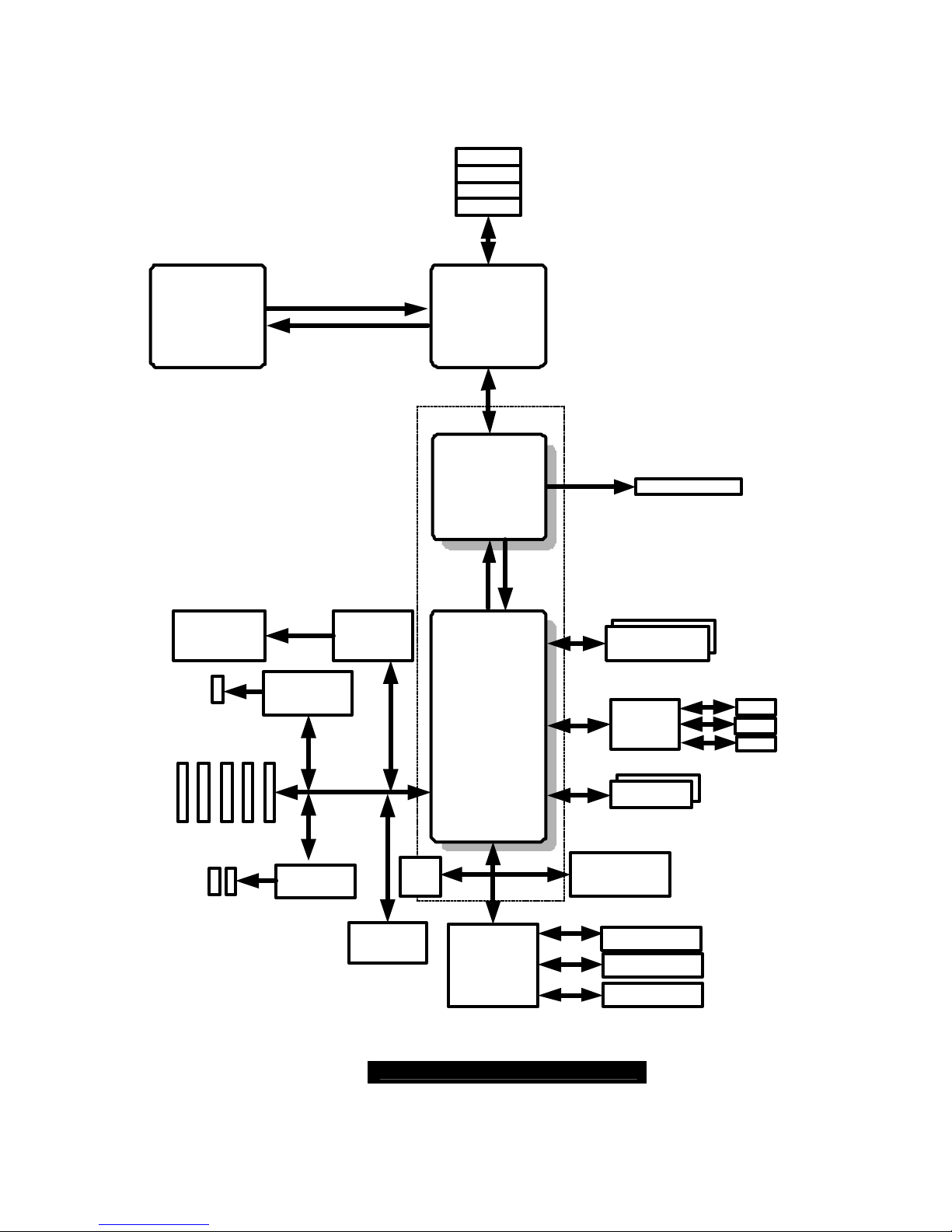
2.01 – Block Diagram
S2875 Tiger K8W Block Diagram
AMD
Opteron
TM
Processor
AMD
AMD-8151
AMD
AMD-8111
DIMM1
DIMM3
DIMM4
Winbond
W83627F/HF
LPC Super I/O
AK2001
Debug system
Floppy Disk Drive
Intel 82541
Gigabit LAN
16x16 Hyper Transport@1600MT/s
AMD Chipset
LPC
AMD
Opteron
TM
Processor
DIMM2
32-Bit/33MHz
Silicon
Image
SiI3114
4 X Serial ATA
RAID Ports
150MB/s
Registered DDR
Memory Bus
DDR 333/266/200
16x16 Hyper Transport@1600MT/s
CODEC
AGP SLOT
PCI
SLOT1
PCI
SLOT2
PCI
SLOT3
PCI
SLOT4
PCI
SLOT5
LAN
VIA 6307
VIA 6212
USB 2.0 x4
IEEE 1394a
Header
IEEE 1394a
Header
LPC
ROM
PS/2 Keyboard &
Mouse
Serial Port x 2
Parallel Port x 1
EIDE(ATA/100) x2
USB 1.1 x4
LINE IN
LINE OUT
MIC IN
LINK 0B
OUT
N
N
OUTLINK 0A
LINK 1
8x8 ncHyper Transport@400MT/s
N OUT
USB Ports: 2 to backplane
2 to header
USB Ports: 2 to backplane
2 to header
http://www.TYAN.com
10
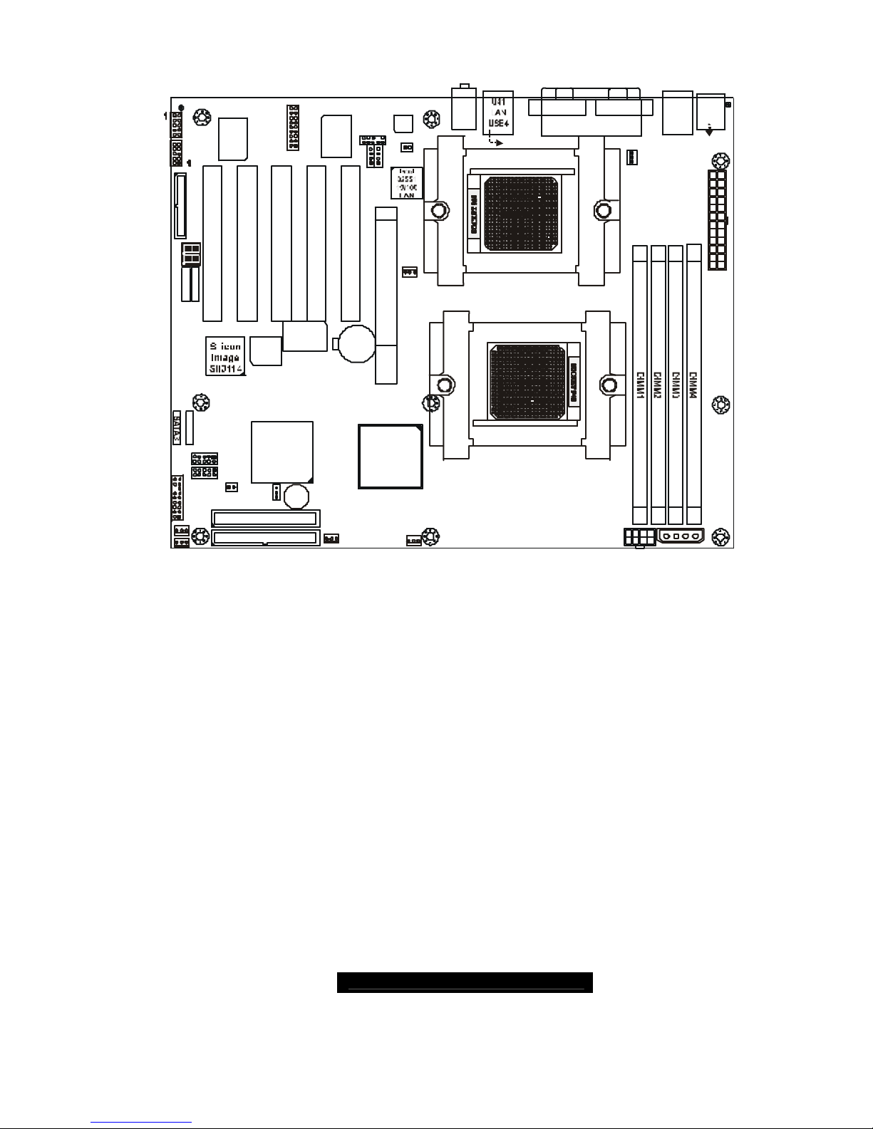
2.02 – Board Parts, Jumpers and Connectors
S2875
1
1
J44
KB-MS
J41
USB1
P2_FAN
J24
FAN2
BIOS
AMD
AMD-8111
SATA2
SATA1
J4
BT1
PRI-IDE
SEC-IDE
1
Winbond
W83627HF
AMD
AMD-8151
PCI2
1394
USB (Bottom)
LAN (Top)Optional
KB(Bottom)
Mouse(Top)
1
PCI1
FAN3
FAN4
FAN1
J22
J6
CPU1
CPU2
BZ1
USB2
SATA4
COM1COM2
LPT1
J39
Audio
ALC655
1
CD1
AUX1
1
AGP1
PCI3PCI4PCI5
VIA 6307
VIA 6212
1394
J21
1
1
J8
CMOS
USB3
J3J2P1_FAN
J23
J33
1
J26
1
J7
FDD
J34
J40
J32
J38
J35 J36
J14
J20
J12
J15
J9
1
J1
J3
Game
Port
This diagram is representative of the latest board revision available at the time of
publishing. The board you receive may not look exactly like the above diagram.

http://www.TYAN.com
11
Jumper Function Settings
J7 Chassis Intrusion Connector
See Section 2.03 for pinout
configuration
J8 Front Panel Connector
See Section 2.04 for pinout
configuration
J9 Clear CMOS Jumper
Close Pin-1 and Pin-2 (Default)
Normal mode
Close Pin-2 and Pin-3
Clear CMOS mode
J12 USB 1.1 Connector Header
See Section 2.06 for pinout
configuration
J15 USB 2.0 Connector Header
See Section 2.07 for pinout
configuration
J22
SATA 1 Connector
See Section 2.08 for pinout
configuration
J21 SATA 2 Connector
See Section 2.08 for pinout
configuration
J20 SATA 3 Connector
See Section 2.08 for pinout
configuration
J14 SATA 4 Connector
See Section 2.08 for pinout
configuration
J26 Gigabit Ethernet LAN
Open: Enable
Close: Disable
J32, J40 IEEE 1394a Header
See Section 2.10 for pinout
configuration
J34 Game Port Header
See Section 2.11 for pinout
configuration
J35 Aux_in Line_in Connector
See Section 2.12 for pinout
configuration
J36 CD Audio_in
See Section 2.13 for pinout
configuration
J38 Front panel audio Header
See Section 2.14 for pinout
configuration
P1_FAN CPU_1 Fan Connector With speed control, MAX 2.0A
P2_FAN CPU_2 Fan Connector With speed control, MAX 2.0A
J2
FAN1
Chassis Fan Connector Without speed control, MAX 3.0A
J3
FAN2
Chassis Fan Connector With speed control, MAX 2.0A
J6
FAN3
Chassis Fan Connector Without speed control, MAX 3.0A
J4
FAN4
Chassis Fan Connector With speed control, MAX 2.0A
http://www.TYAN.com
12
Jumper Legend
OPEN - Jumper OFF without jumper cover
CLOSED - Jumper ON with jumper cover
2.03 – Chassis Intrusion Connector (J7)
Pin-1
Intrusion detection
Pin-2
GND
S2875
1
1
J44
KB-MS
J41
USB1
P2_FAN
J24
FAN2
BIOS
AMD
AMD-8111
SATA2
SATA1
J4
BT1
PRI-IDE
SEC-IDE
1
Winbond
W83627HF
AMD
AMD-8151
PCI2
1394
USB (Bottom)
LAN (Top)Optional
KB(Bottom)
Mouse(Top)
1
PCI1
FAN3
FAN4
FAN1
J22
J6
CPU1
CPU2
BZ1
USB2
SATA3
SATA4
COM1COM2
LPT1
J39
Audio
ALC655
1
CD1
AUX1
1
AGP1
PCI3PCI4PCI5
VIA 6307
VIA 6212
1394
J21
1
1
J8
CMOS
USB3
J3J2P1_FAN
J23
J33
1
J26
1
J7
FDD
J34
J40
J32
J38
J35
J36
J14
J20
J12
J15
J9
1
J1
J3
Game
Port
For use with chassis that support
this feature
2.04 – Front Panel Connector (J8)
1 2
17 18
PWR-LED
RESET
INFRARED
HD-LED
POWER
SPEAKER
INTRU
SLEEP
Function PIN PIN Function
Power
LED+
1 2
HDD LED+
Power LED -
3 4
HDD LED -
Reset SW -
5 6
PWR+
Reset SW+
7 8
GND
+5V
9 10
SLEEP SW
+
IRRX
11 12
+5V
GND
13 14
GND
IRTX
15 16
GND
S2875
1
1
J44
KB-MS
J41
USB1
P2_FAN
J24
FAN2
BIOS
AMD
AMD-8111
SATA2
SATA1
J4
BT1
PRI-IDE
SEC-IDE
1
Winbond
W83627HF
AMD
AMD-8151
PCI2
1394
USB (Bottom)
LAN (Top)Optional
KB(Bottom)
Mouse(Top)
1
PCI1
FAN3
FAN1
J22
J6
CPU1
CPU2
BZ1
USB2
SATA3
SATA4
COM1COM2
LPT1
J39
Audio
ALC655
1
CD1AUX1
1
AGP1
PCI3PCI4PCI5
VIA 6307
VIA 6212
1394
J21
1
1
J8
CMOS
USB3
J3J2P1_FAN
J23
J33
1
J26
1
J7
FD D
J34
J40
J32
J38
J35 J36
J14
J20
J12
J15
J9
1
J1
J3
Game
Port
FAN4
Chassis
Intru +
17 18
Speaker
http://www.TYAN.com
13
2.05 – Clear CMOS Jumper (J9)
3
1
Default
3
1
Clear
S2875
1
1
J44
KB-MS
J41
USB1
P2_FAN
J24
FAN2
BIOS
AMD
AMD-8111
SATA2
SATA1
J4
BT1
PRI-IDE
SEC-IDE
1
Winbond
W83627HF
AMD
AMD-8151
PCI2
1394
USB (Bottom)
LAN (Top)Optional
KB(Bottom)
Mouse(Top)
1
PCI1
FAN3
FAN4
FAN1
J22
J6
CPU1
CPU2
BZ1
USB2
SATA3
SATA4
COM1COM2
LPT1
J39
Audio
ALC655
1
CD1AUX1
1
AGP1
PCI3PCI4PCI5
VIA 6307
VIA 6212
1394
J21
1
1
J8
CMOS
USB3
J3J2P1_FAN
J23
J33
1
J26
1
J7
FDD
J34
J40
J32
J38
J35
J36
J14
J20
J12
J15
J9
1
J1
J3
Game
Port
You can reset the CMOS settings by
using this jumper if you have forgotten
your system/setup password or need to
clear system BIOS setting.
- Power off system and disconnect
both power connectors from
the motherboard
- Use jumper cap to close Pin_2
and Pin_3 for several seconds to
Clear CMOS
- Put jumper cap back to Pin_1 and
Pin_2 (default setting)
Reconnect power & power on system
2.06 – USB1.1 Connector Header (J12)
10 2
9 1
GND
GND
Data 1+
Data 1 -
+5V
9 7 5 3 1
10 8 6 4 2
FAN4
S2875
1
1
J44
KB-MS
J41
USB1
P2_FAN
J24
FAN2
BIOS
AMD
AMD-8111
SATA2
SATA 1
J4
BT1
PRI-IDE
SEC-IDE
1
Winbond
W83627HF
AMD
AMD-8151
PCI2
1394
USB (Bottom)
LAN (Top)Optional
KB(Bottom)
Mouse(Top)
1
PCI1
FAN3
FAN1
J22
J6
CPU1
CPU2
BZ1
USB2
SATA3
SATA4
COM1COM2
LPT1
J39
Audio
ALC655
1
CD1AUX1
1
AGP1
PCI3PCI4PCI5
VIA 6307
VIA 6212
1394
J21
1
1
J8
CMOS
USB3
J3J2P1_FAN
J23
J33
1
J26
1
J7
FDD
J34
J40
J32
J38
J35 J36
J14
J20
J12
J15
J9
1
J1
J3
Game
Port
GND
GND
Data 2+
Data 2 -
+5V
http://www.TYAN.com
14
2.07 – USB 2.0 Connector Header (J15)
10 2
9 1
GND
GND
Data 1+
Data 1 -
+5V
9 7 5 3 1
10 8 6 4 2
S2875
1
1
J44
KB-MS
J41
USB1
P2_FAN
J24
FAN2
BIOS
AMD
AMD-8111
SATA2
SATA 1
J4
BT1
PRI-IDE
SEC-IDE
1
Winbond
W83627HF
AMD
AMD-8151
PCI2
1394
USB (Bottom)
LAN (Top)Optional
KB(Bottom)
Mouse(Top)
1
PCI1
FAN3
FAN4
FAN1
J22
J6
CPU1
CPU2
BZ1
USB2
SATA3
SATA4
COM1COM2
LPT1
J39
Audio
ALC655
1
CD1AUX1
1
AGP1
PCI3PCI4PCI5
VIA 6307
VIA 6212
1394
J21
1
1
J8
CMOS
USB3
J3J2P1_FAN
J23
J33
1
J26
1
J7
FDD
J34
J40
J32
J38
J35 J36
J14
J20
J12
J15
J9
1
J1
J3
Game
Port
GND
GND
Data 2+
Data 2 -
+5V
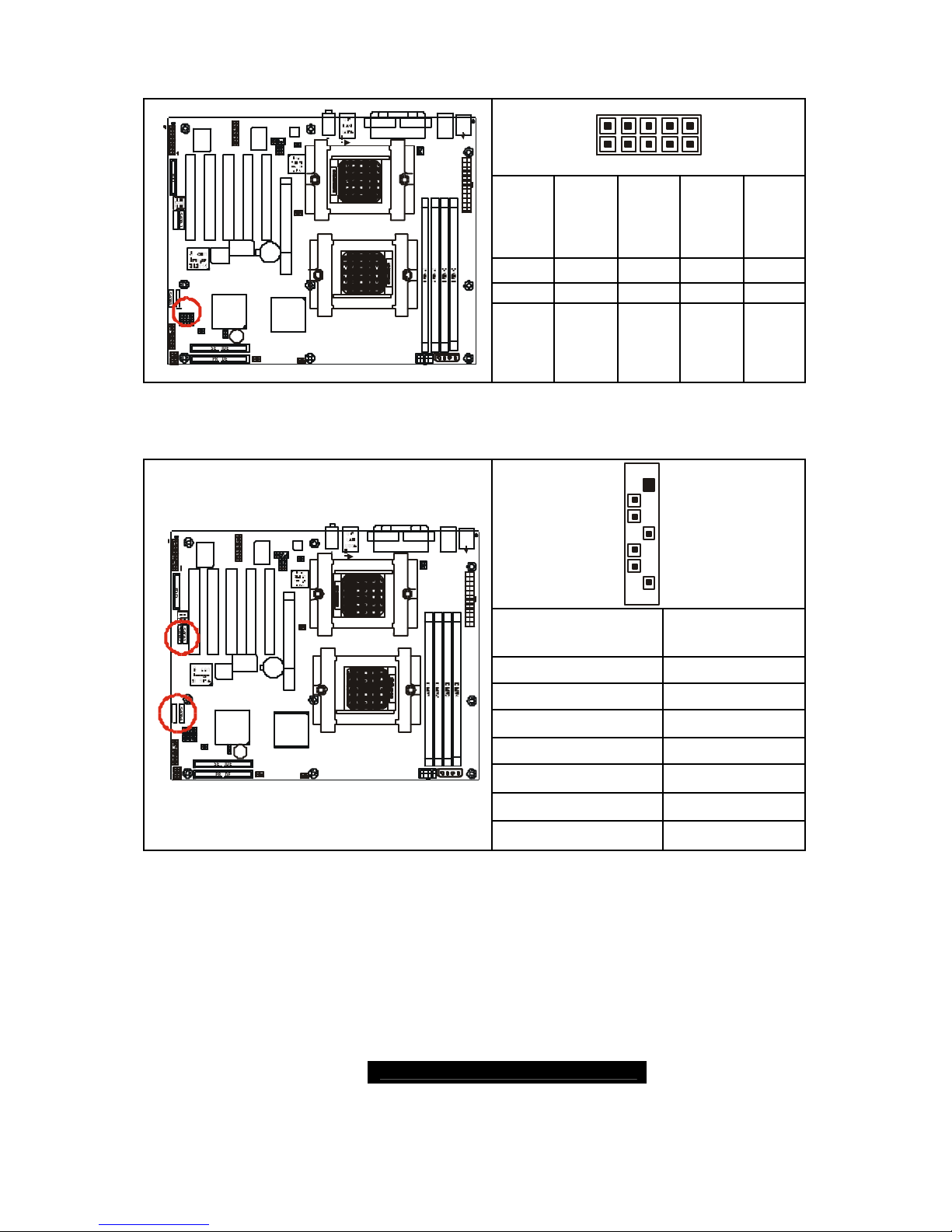
2.08 – SATA Connectors (J22 / J21 / J20 / J14)
1
7
Signal Description Pin#
VCC
1
GND
2
XTPBM
3
XTPBP
4
XTPAM
5
XTPAP
6
S2875
1
1
J44
KB-MS
J41
USB1
P2_FAN
J24
FAN2
BIOS
AMD
AMD-8111
SATA2
SATA1
J4
BT1
PRI-IDE
SEC-IDE
1
Winbond
W83627HF
AMD
AMD-8151
PCI2
1394
USB (Bottom)
LAN (Top)Optional
KB(Bottom)
Mouse(Top)
1
PCI1
FAN3
FAN4
FAN1
J22
J6
CPU1
CPU2
BZ1
USB2
SATA3
SATA4
COM1COM2
LPT1
J39
Audio
ALC655
1
CD1AUX1
1
AGP1
PCI3PCI4PCI5
VIA 6307
VIA 6212
1394
J21
1
1
J8
CMOS
USB3
J3J2P1_FAN
J23
J33
1
J26
1
J7
FD D
J34
J40
J32
J38
J35 J36
J14
J20
J12
J15
J9
1
J1
J3
Game
Port
GND
7
http://www.TYAN.com
15
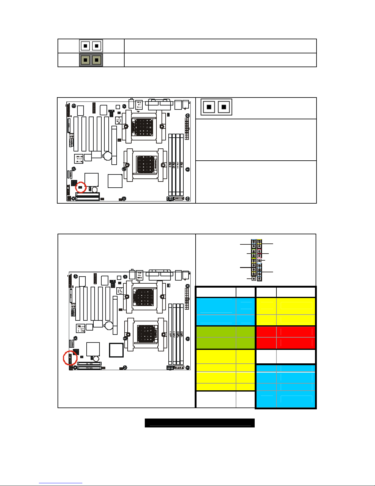
2.09 – Onboard Gigabit Ethernet LAN Jumper (J26)
OPEN (Default)
To enable onboard Gigabit Ethernet
(Both ports)
S2875
1
1
J44
KB-MS
J41
USB1
P2_FAN
J24
FAN2
BIOS
AMD
AMD-8111
SATA2
SATA1
J4
BT1
PRI-IDE
SEC-IDE
1
Winbond
W83627HF
AMD
AMD-8151
PCI2
1394
USB (Bottom)
LAN (Top)Optional
KB(Bottom)
Mouse(Top)
1
PCI1
FAN3
FAN1
J22
J6
CPU1
CPU2
BZ1
USB2
SATA3
SATA4
COM1COM2
LPT1
J39
Audio
ALC655
1
CD1AUX1
1
AGP1
PCI3PCI4PCI5
VIA 6307
VIA 6212
1394
J21
1
1
J8
CMOS
USB3
J3J2P1_FAN
J23
J33
1
J26
1
J7
FDD
J34
J40
J32
J38
J35
J36
J14
J20
J12
J15
J9
1
J1
J3
Game
Port
FAN4
CLOSED
To disable onboard Gigabit Ethernet
(Both ports)
2.10 – IEEE 1394a Header (J32 / J40)
J32
1029
1
Signal
Description
Pin Pin
Signal
Description
10 9
GND
8 7
GND
XYPAP
6 5
XTPAM
XTPBP
4 3
XTPBM
GND
2 1
VCC
J40
192
10
Signal
Description
Pin Pin
Signal
Description
VCC
1 2
GND
XTPBM
3 4
XTPBP
XTPAM
5 6
XYPAP
GND
7 8
GND
S2875
1
1
J44
KB-MS
J41
USB1
P2_FAN
J24
FAN2
BIOS
AMD
AMD-8111
SATA2
SATA1
J4
BT1
PRI-IDE
SEC-IDE
1
Winbond
W83 62 7HF
AMD
AMD-8151
PCI2
1394
USB (Bottom)
LAN (Top)Optional
KB(Bottom)
Mouse(Top)
1
PCI1
FAN3
FAN4
FAN1
J22
J6
CPU1
CPU2
BZ1
USB2
SATA3
SATA4
COM1COM2
LPT1
J39
Audio
ALC655
1
CD1AUX1
1
AGP1
PCI3PCI4PCI5
VIA 6 30 7
VIA 6212
1394
J21
1
1
J8
CMOS
USB3
J3J2P1_FAN
J23
J33
1
J26
1
J7
FDD
J34
J40
J32
J38
J35
J36
J14
J20
J12
J15
J9
1
J1
J3
Game
Port
9 10
http://www.TYAN.com
16
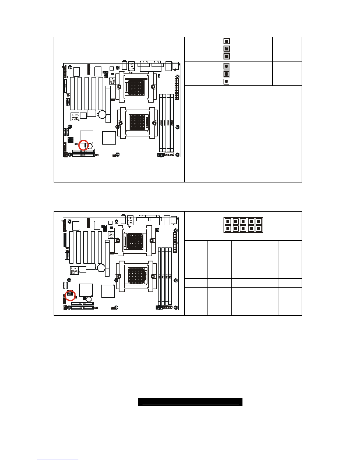
2.11 – Game Port Header (J34)
2161
15
Signal
Description
Pin Pin
Signal
Description
G5V
1 2
G5V
RGSA1
3 4
RGSB1
RGPX1
5 6
RGPX2
GND
7 8
RMSO
GND
9 10
RGPY2
RGPY1
11 12
RGSB2
RGSA2
13 14
RMSI
S2875
1
1
J44
KB-MS
J41
USB1
P2_FAN
J24
FAN2
BIOS
AMD
AMD-8111
SATA2
SATA 1
J4
BT1
PRI-IDE
SEC-IDE
1
Winbond
W83627HF
AMD
AMD-8151
PCI2
1394
USB (Bottom)
LAN (Top)Optional
KB(Bottom)
Mouse(Top)
1
PCI1
FAN3
FAN4
FAN1
J22
J6
CPU1
CPU2
BZ1
USB2
SATA3
SATA4
COM1COM2
LPT1
J39
Audio
ALC655
1
CD1AUX1
1
AGP1
PCI3PCI4PCI5
VIA 6307
VIA 6212
1394
J21
1
1
J8
CMOS
USB3
J3J2P1_FAN
J23
J33
1
J26
1
J7
FDD
J34
J40
J32
J38
J35 J36
J14
J20
J12
J15
J9
1
J1
J3
Game
Port
G5V
15 16
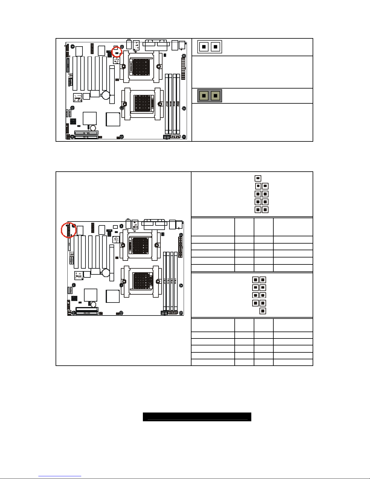
2.12 – Aux_in Line_in Connector (J35)
4
1
Signal Description Pin#
Right Line_In
4
GND
3
GND
2
S2875
1
1
J44
KB-MS
J41
USB1
P2_FAN
J24
FAN2
BIOS
AMD
AMD-8111
SATA2
SATA1
J4
BT1
PRI-IDE
SEC-IDE
1
Winbond
W83627HF
AMD
AMD-8151
PCI2
1394
USB (Bottom)
LAN (Top)Optional
KB(Bottom)
Mouse(Top)
1
PCI1
FAN3
FAN1
J22
J6
CPU1
CPU2
BZ1
USB2
SATA3
SATA4
COM1COM2
LPT1
J39
Audio
ALC655
1
CD1
AUX1
1
AGP1
PCI3PCI4PCI5
VIA 6307
VIA 6212
1394
J21
1
1
J8
CMOS
USB3
J3J2P1_FAN
J23
J33
1
J26
1
J7
FDD
J34
J40
J32
J38
J35
J36
J14
J20
J12
J15
J9
1
J1
J3
Game
Port
FAN4
Left Line_In
1

http://www.TYAN.com
17
2.13 – CD Audio_in Connector (J36)
4
1
Signal Description Pin
CD_In_Right
4
CD_Reference
3
CD_Reference
2
S2875
1
1
J44
KB-MS
J41
USB1
P2_FAN
J24
FAN2
BIOS
AMD
AMD-8111
SATA2
SATA1
J4
BT1
PRI-IDE
SEC-IDE
1
Winbond
W83627HF
AMD
AMD-8151
PCI2
1394
USB (Bottom)
LAN (Top)Optional
KB(Bottom)
Mouse(Top)
1
PCI1
FAN3
FAN4
FAN1
J22
J6
CPU1
CPU2
BZ1
USB2
SATA3
SATA4
COM1COM2
LPT1
J39
Audio
ALC655
1
CD1AUX1
1
AGP1
PCI3PCI4PCI5
VIA 6307
VIA 6212
1394
J21
1
1
J8
CMOS
USB3
J3J2P1_FAN
J23
J33
1
J26
1
J7
FD D
J34
J40
J32
J38
J35 J36
J14
J20
J12
J15
J9
1
J1
J3
Game
Port
CD_In _Left
1
2.14 – Front Panel Audio Header (J38)
2110
9
OPEN
Front panel audio output(via an
optional cable, not included in the box)
2110
9
S2875
1
1
J44
KB-MS
J41
USB1
P2_FAN
J24
FAN2
BIOS
AMD
AMD-8111
SATA2
SATA1
J4
BT1
PRI-IDE
SEC-IDE
1
Winbond
W83627HF
AMD
AMD-8151
PCI2
1394
USB (Bottom)
LAN (Top)Optional
KB(Bottom)
Mouse(Top)
1
PCI1
FAN3
FAN4
FAN1
J22
J6
CPU1
CPU2
BZ1
USB2
SATA3
SATA4
COM1COM2
LPT1
J39
Audio
ALC655
1
CD1AUX1
1
AGP1
PCI3PCI4PCI5
VIA 6307
VIA 6212
1394
J21
1
1
J8
CMOS
USB3
J3J2P1_FAN
J23
J33
1
J26
1
J7
FDD
J34
J40
J32
J38
J35
J36
J14
J20
J12
J15
J9
1
J1
J3
Game
Port
CLOSED
Real panel audio output
2.15 – CPU_1 Fan Connector (P1_FAN)
+12V
GND
Speed
S2875
1
1
J44
KB-MS
J41
USB1
P2_FAN
J24
FAN2
BIOS
AMD
AMD-8111
SATA2
SATA1
J4
BT1
PRI-IDE
SEC-IDE
1
Winbond
W83627HF
AMD
AMD-8151
PCI2
1394
USB (Bottom)
LAN (Top)Optional
KB(Bottom)
Mouse(Top)
1
PCI1
FAN3
FAN4
FAN1
J22
J6
CPU1
CPU2
BZ1
USB2
SATA3
SATA4
COM1COM2
LPT1
J39
Audio
ALC655
1
CD1
AUX1
1
AGP1
PCI3PCI4PCI5
VIA 6307
VIA 6212
1394
J21
1
1
J8
CMOS
USB3
J3J2P1_FAN
J23
J33
1
J26
1
J7
FDD
J34
J40
J32
J38
J35
J36
J14
J20
J12
J15
J9
1
J1
J3
Game
Port
Max 2.0A fans supported
with PWM fan control and fan speed
reading
http://www.TYAN.com
18
2.16– CPU_2 Fan Connector (P2_FAN)
+12V
Speed
GND
S2875
1
1
J44
KB-MS
J41
USB1
P2_FAN
J24
FAN2
BIOS
AMD
AMD-8111
SATA2
SATA1
J4
BT1
PRI-IDE
SEC-IDE
1
Winbond
W83627HF
AMD
AMD-8151
PCI2
1394
USB (Bottom)
LAN (Top)Optional
KB(Bottom)
Mouse(Top)
1
PCI1
FAN3
FAN1
J22
J6
CPU1
CPU2
BZ1
USB2
SATA3
SATA4
COM1COM2
LPT1
J39
Audio
ALC655
1
CD1
AUX1
1
AGP1
PCI3PCI4PCI5
VIA 6307
VIA 6212
1394
J21
1
1
J8
CMOS
USB3
J3J2P1_FAN
J23
J33
1
J26
1
J7
FDD
J34
J40
J32
J38
J35
J36
J14
J20
J12
J15
J9
1
J1
J3
Game
Port
FAN4
Max 2.0A fans supported
with PWM fan control and fan speed
reading
2. 17 – FAN 1 Chassis Fan Connector (J2)
+12V
Speed
GND
S2875
1
1
J44
KB-MS
J41
USB1
P2_FAN
J24
FAN2
BIOS
AMD
AMD-8111
SATA2
SATA1
J4
BT1
PRI-IDE
SEC-IDE
1
Winbond
W83627HF
AMD
AMD-8151
PCI2
1394
USB (Bottom)
LAN (Top)Optional
KB(Bottom)
Mouse(Top)
1
PCI1
FAN3
FAN4
FAN1
J22
J6
CPU1
CPU2
BZ1
USB2
SATA3
SATA4
COM1COM2
LPT1
J39
Audio
ALC655
1
CD1
AUX1
1
AGP1
PCI3PCI4PCI5
VIA 6307
VIA 6212
1394
J21
1
1
J8
CMOS
USB3
J3J2P1_FAN
J23
J33
1
J26
1
J7
FDD
J34
J40
J32
J38
J35
J36
J14
J20
J12
J15
J9
1
J1
J3
Game
Port
Max 2.0A fans supported
with PWM fan control and fan speed
reading
2.18 – FAN 2 Chassis Fan Connector (J3)
+12V
Speed
GND
S2875
1
1
J44
KB-MS
J41
USB1
P2_FAN
J24
FAN2
BIOS
AMD
AMD-8111
SATA2
SATA1
J4
BT1
PRI-IDE
SEC-IDE
1
Winbond
W83627HF
AMD
AMD-8151
PCI2
1394
USB (Bottom)
LAN (Top)Optional
KB(Bottom)
Mouse(Top)
1
PCI1
FAN3
FAN4
FAN1
J22
J6
CPU1
CPU2
BZ1
USB2
SATA 3
SATA 4
COM1COM2
LPT1
J39
Audio
ALC655
1
CD1
AUX1
1
AGP1
PCI3PCI4PCI5
VIA 6307
VIA 6212
1394
J21
1
1
J8
CMOS
USB3
J3J2P1_FAN
J23
J33
1
J26
1
J7
FDD
J34
J40
J32
J38
J35
J36
J14
J20
J12
J15
J9
1
J1
J3
Game
Port
Max 2.0A fans supported
with PWM fan control and fan speed
reading
http://www.TYAN.com
19
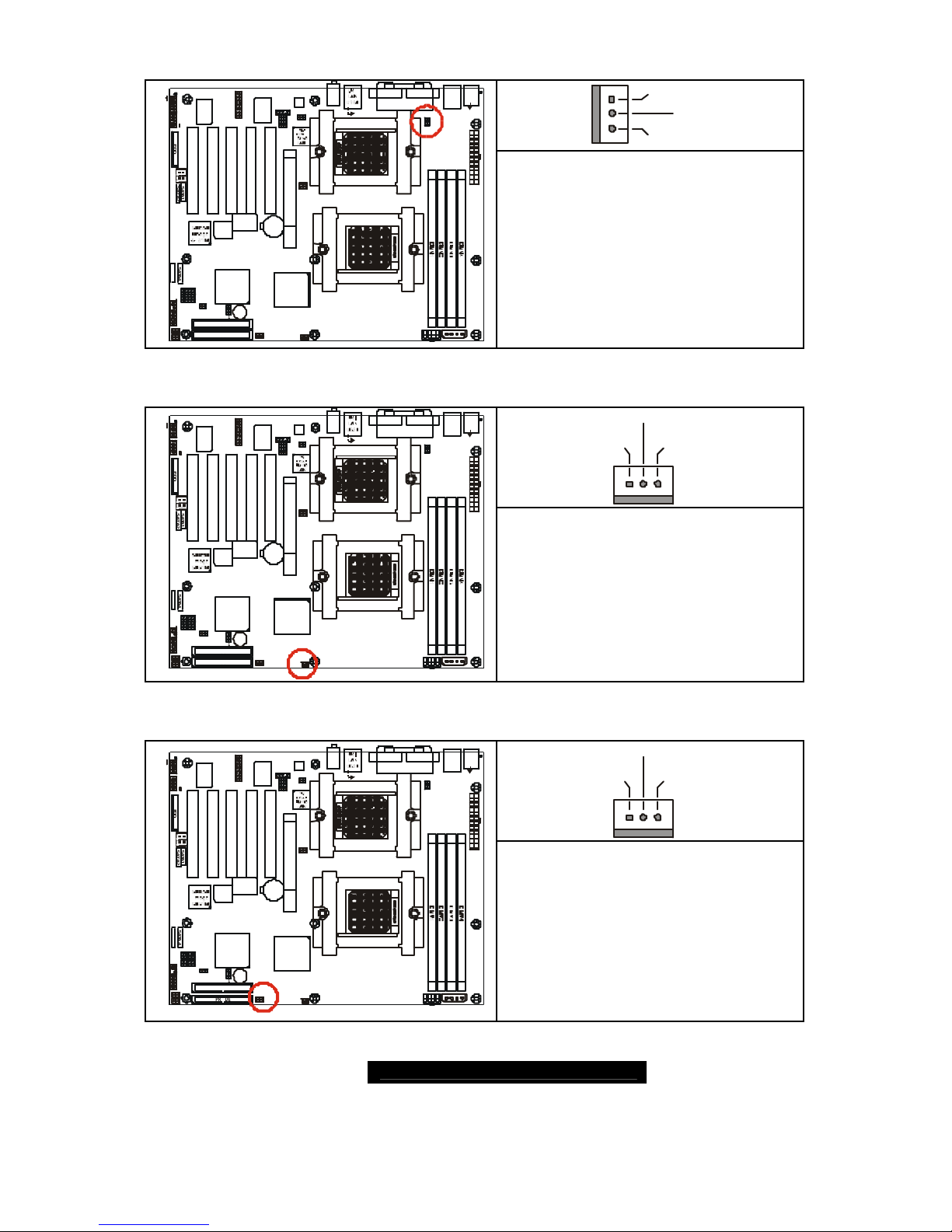
2.19 – FAN3 Chassis Fan Connector (J6)
+12V
Speed
GND
S2875
1
1
J44
KB-MS
J41
USB1
P2_FAN
J24
FAN2
BIOS
AMD
AMD-8111
SATA2
SATA1
J4
BT1
PRI-IDE
SEC-IDE
1
Winbond
W83627HF
AMD
AMD-8151
PCI2
1394
USB (Bottom)
LAN (Top)Optional
KB(Bottom)
Mouse(Top)
1
PCI1
FAN4
FAN1
J22
J6
CPU1
CPU2
BZ1
USB2
SATA3
SATA4
COM1COM2
LPT1
J39
Audio
ALC655
1
CD1
AUX1
1
AGP1
PCI3PCI4PCI5
VIA 6307
VIA 6212
1394
J21
1
1
J8
CMOS
USB3
J3J2P1_FAN
J23
J33
1
J26
1
J7
FDD
J34
J40
J32
J38
J35
J36
J14
J20
J12
J15
J9
1
J1
J3
Game
Port
FAN3
Max 2.0A fans supported
with PWM fan control and fan speed
reading
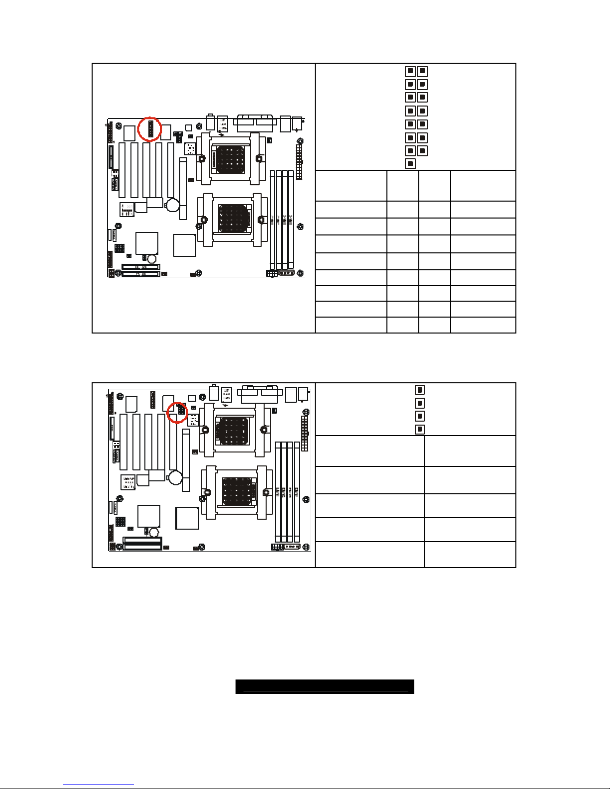
2.20 – FAN 4 Chassis Fan Connector (J4)
+12V
Speed
GND
S2875
1
1
J44
KB-MS
J41
USB1
P2_FAN
J24
FAN2
BIOS
AMD
AMD-8111
SATA2
SATA1
J4
BT1
PRI-IDE
SEC-IDE
1
Winbond
W83627HF
AMD
AMD-8151
PCI2
1394
USB (Bottom)
LAN (Top)Optional
KB(Bottom)
Mouse(Top)
1
PCI1
FAN3
FAN1
J22
J6
CPU1
CPU2
BZ1
USB2
SATA3
SATA 4
COM1COM2
LPT1
J39
Audio
ALC655
1
CD1AUX1
1
AGP1
PCI3PCI4PCI5
VIA 6307
VIA 6212
1394
J21
1
1
J8
CMOS
USB3
J3J2P1_FAN
J23
J33
1
J26
1
J7
FDD
J34
J40
J32
J38
J35 J36
J14
J20
J12
J15
J9
1
J1
J3
Game
Port
FAN4
Max 3.0A fans supported
without PWM fan control
without fan speed reading
2.21 – OEM Reserved Connectors and Jumpers
These connectors and jumpers which are not listed are reserved for OEM use
only.
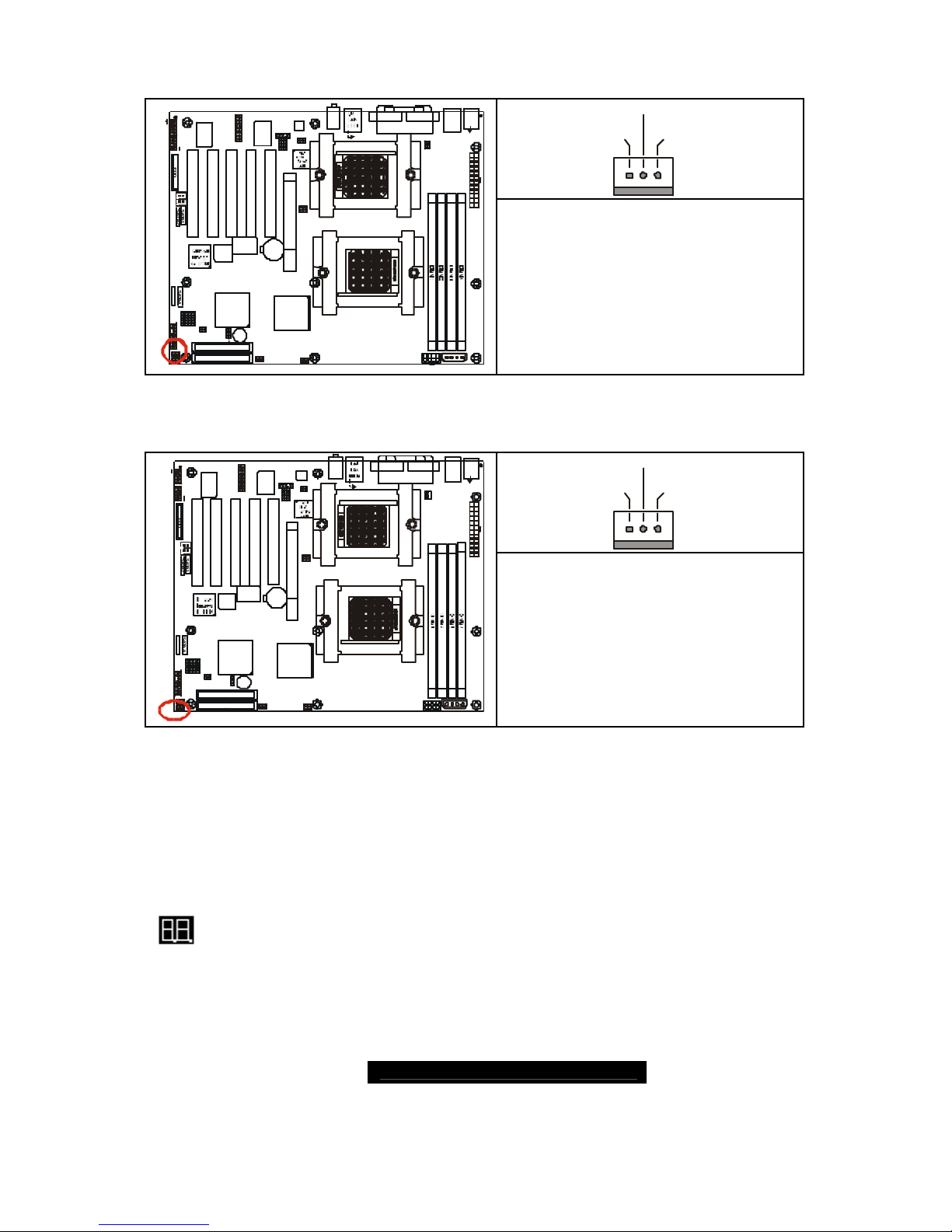
2.22 – POST (Power-On-Self-Test) Code LED
Refer to Appendix II for BIOS POST Code list
http://www.TYAN.com
20
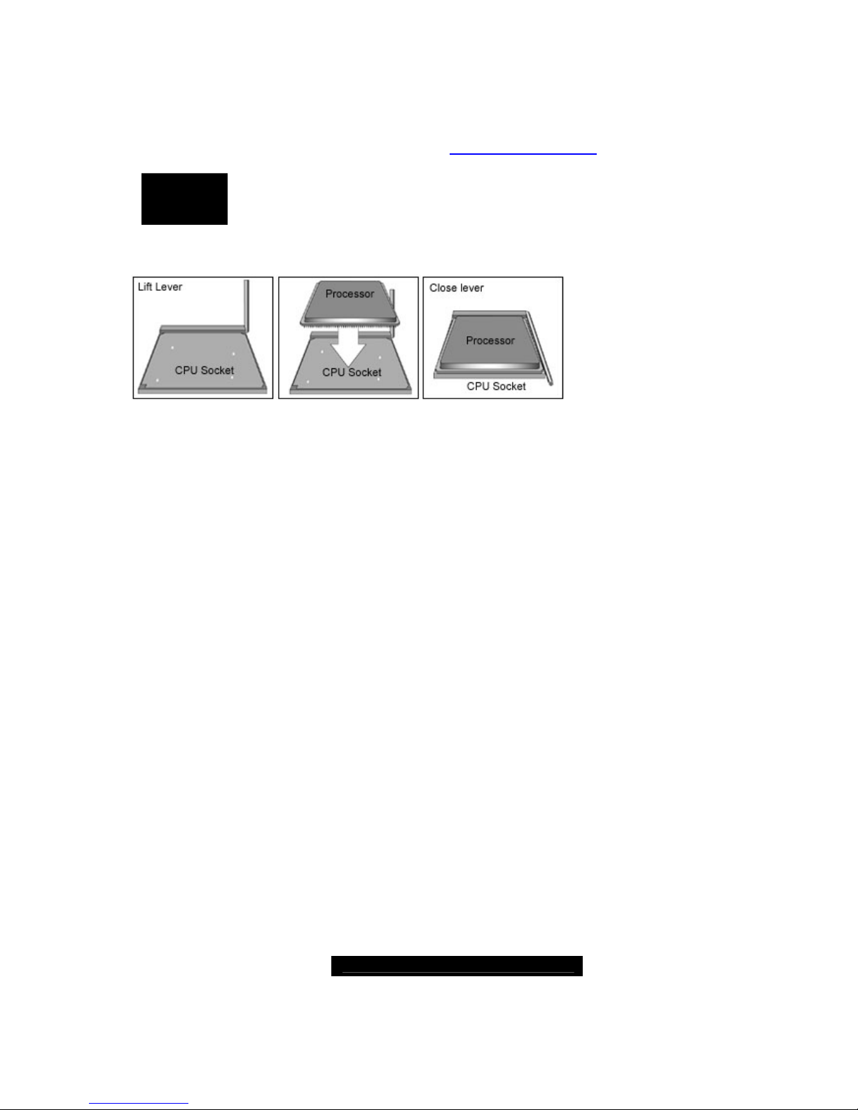
2.23 – Installing the Processor(s)
Your brand new T iger K8W supports the latest 64-bit processor technologies from AMD.
Only AMD Opteron™ processor 200 series are certified and supported with this
motherboard.
Check our website for latest processor support. http://www.tyan.com
NOTE
If using a single processor, it MUST be installed in socket CPU1.
When using a single processor only CPU1 memory banks are
addressable.
TYAN is not liable for damage as a result of operating an unsupported configuration.
The diagram is provided as a visual guide to help you install socket processors and may
not be an exact representation of the processors you have.
Lift the lever on the socket until it is approximately 90o or as far back as possible to the
socket.
Align the processor with the socket. There are keyed pins unde rneath the processor to
ensure that the processor’s installed correctly.
Seat the processor firmly into the socket by gently pressing down until the processor sits
flush with the socket.
Place the socket lever back down until it locks into place.
Your processor is installed.
Repeat these steps for the second processor if you are using two processors.
Take care when installing processors as they have very fragile connector pins below the
processor and can bend and break if inserted improperly.
http://www.TYAN.com
21
2.24 - Heatsink Retention Frame Installation
After you are done installing the processor(s), you should proceed to installing the
retention frame and heatsink. The CPU heatsink will ensure that the processors do not
overheat and continue to operate at maximum performance for as long as you own them.
Overheated processors are also dangerous to the health of the motherboard.
The backplate assembly prevents excessive motherboard flexing in the area near the
processor and provides a base for the installation of the heatsink retention bracket and
heatsink.
Because there are many different types of heatsinks available from many different
manufacturers, a lot of them have their own method of installation. For the safest method
of installation and information on choosing the appropriate heatsink, use heatsinks
validated by AMD. Please refer to AMD’s website at www.amd.com.
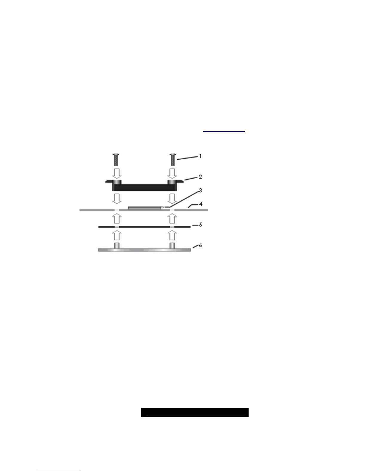
The following diagram will illustrate how to install the most common CPU back plates:
Mounting screws
Heatsink retention frame
CPU socket
Motherboard PCB
Adhesive insulator material
Backplate assembly
NOTE: Please see next section
for specific instructions on how
to install mounting bracket.
http://www.TYAN.com
22
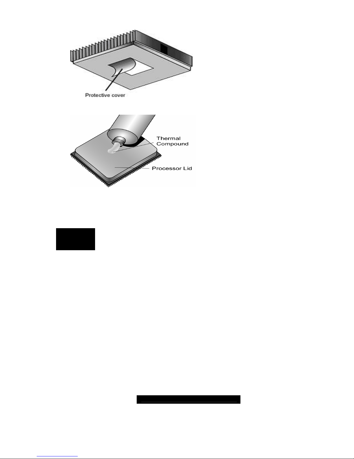
2.25 -- Thermal Interface Material
There are two types of thermal
interface materials designed for
use with the AMD Opteron
processor.
The most common material
comes as a small pad attached
to the heatsink at the time of
purchase. There should be a
protective cover over the
material. Take care not to touch
this material.
Simply remove the protective
cover and place the heatsink on
the processor.
The second type of interface
material is usually packaged
separately. It is commonly
referred to as ‘thermal
compound’. Simply apply a thin
layer on to the CPU lid (applying
too much will actually reduce the
cooling).
NOTE
Al ways check with the manufacturer of the heatsink & processor to
ensure the Thermal Interface material is compatible with the
processor & meets the manufacturer’s warranty requirements
 Loading...