

TYAN Tiger i7501R S2735, S2735 User Manual

1
http://www.TYAN.com
Tiger i7501R
///
S2735
Revision 1.00
Copyright © TYAN Computer Corporation, 2003 - 2004. All rights reserved. No part of this manual
may be reproduced or translated without prior written consent from TYAN Computer Corp.
All registered and unregistered trademarks and company names contained in this manual are
property of their respective owners including, but not limited to the following.
TYAN, Tiger i7501R S2735 are trademarks of TYAN Computer Corporation.
Intel, Xeon, and combinations thereof are trademarks of Intel Corporation.
AMI, AMIBIOS are trademarks of AMI Software Incorporated.
Microsoft, Windows are trademarks of Microsoft Corporation.
Linux is a trademark of Linus Torvalds
QLogic, Zircon, and combinations thereof are trademarks of QLogic Corporation.
IBM, PC, AT, PS/2 are trademarks of IBM Corporation.
Winbond is a trademark of Winbond Electronics Corporation.
ATI and Rage XL are trademarks of ATI Corporation.
Adaptec, HostRAID and the Adaptec logo are trademarks of Adaptec, Inc.
Portable Document Format (PDF) is a trademark of Adobe Corporation.
Information contained in this document is furnished by TYAN Computer Corporation and has been
reviewed for accuracy and reliability prior to printing. TYAN assumes no liability whatsoever, and
disclaims any express or implied warranty, relating to sale and/or use of TYAN products including
liability or warranties relating to fitness for a particular purpose or merchantability. TYAN retains the
right to make changes to product descriptions and/or specifications at any time, without notice. In
no event will TYAN be held liable for any direct or indirect, incidental or consequential damage,
loss of use, loss of data or other malady resulting from errors or inaccuracies of information
contained in this document.

2
http://www.TYAN.com
Table of Contents
Before you begin… Page 4
Chapter 1: Introduction
1.1 Congratulations Page 5
1.2 Hardware Specifications Page 5
Chapter 2: Board Installation
2.1 Board Image Page 8
2.2 Block Diagram of S2735 Page 9
2.3 Board Parts, Jumpers and Connectors Page 10
2.4 Jumper Settings Page 11
2.5 Jumper Definitions Page 11
2.6 Force 400MHz FSB instead of 533MHz FSB Header (J16) Page 11
2.7 PCI-X A (PCI1) Speed Header (J21) Page 12
2.8 10/100 Ethernet LAN1 LED Header (J22) Page 12
2.9 Gigabit Ethernet LAN2 (J15) LED Header (J23) and Gigabit Ethernet
LAN3 (J14) LED Header (J24)
Page 12
2.10 Buzzer (System Speaker) (J25) Page 13
2.11 SO-DIMM Connector (J26) Page 13
2.12 SMDC (System Management Daughter Card) Connector (J29) Page 13
2.13 Hard Disk Activity LED External Input (J31) Page 14
2.14 Clear CMOS Jumper (J33) Page 14
2.15 Front USB Header (J34) Page 15
2.16 COM2 Header (J36) Page 15
2.17 Front Panel Connector (J39) Page 16
2.18 PCI-X B (PCI2) Speed Header (J43) Page 16
2.19 Fan Header Information Page 17
2.20 PCI Setup Page 18
2.21 Mounting the Motherboard Page 19
2.22 Installing the Memory Page 20
2.23 Installing the Processor and Heatsink Page 24
2.24 Installing CPU Back-plates and retention modules Page 25
2.25 Attaching Drive Cables Page 28
2.26 Installing Add-In Cards Page 30
2.27 Connecting External devices Page 31
2.28 Installing the Power Supply Page 32
2.29 Finishing Up Page 32
Chapter 3: BIOS
3.0 BIOS Setup Utility Page 33
3.1 BIOS Menu Bar Page 34
3.2 BIOS Legend Bar Page 34
3.3 BIOS Main Menu Page 35
3.4 BIOS Advanced Menu Page 36
3.5 BIOS PCI/PnP Menu Page 51
3.6 BIOS Boot Settings Menu Page 53
3.7 BIOS Security Menu Page 59
3.8 BIOS Chipset Setting Menu Page 60
3.9 BIOS Exit Menu Page 64
Chapter 4: SATA/RAID Setup (Option)
4.1 BIOS Configuration Page 65
4.2 Installing Serial ATA (SATA) hard disks Page 65
4.3 Adaptec RAID Configuration Utility Page 66
4.4 Manage Array Page 67

3
http://www.TYAN.com
4.5 Create Array Page 67
4.6 Add/Delete Hotspare Page 69
4.7 Initialize Drives Page 70
4.8 Disk Utilities Page 71
Chapter 5: Diagnostics Page 73
Appendix I: Glossary Page 77
Appendix II: SMDC Information Page 83
Appendix III: Riser Cards Page 84
Appendix IV: SCSI Daughter Card Information Page 84
Technical Support Page 85
4
http://www.TYAN.com
Before you begin…
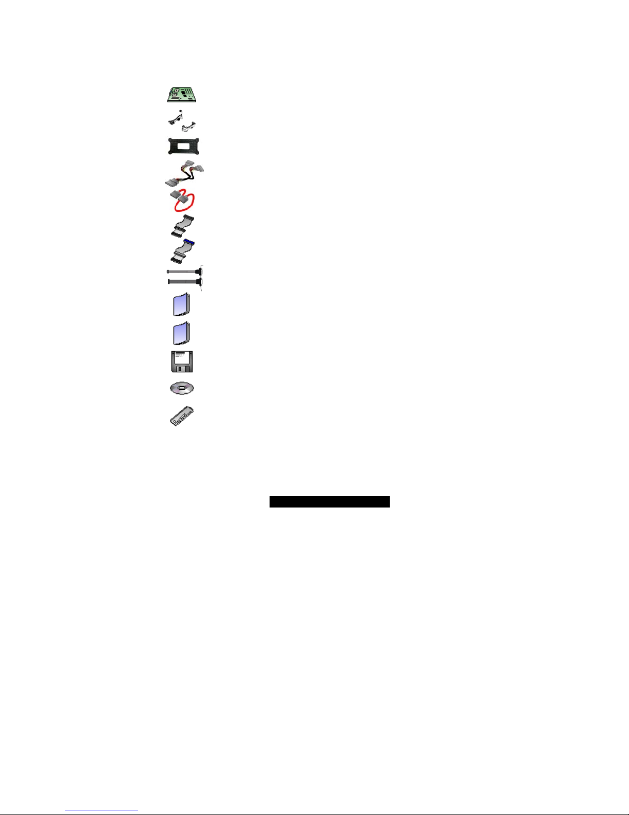
Check the box contents!
The retail motherboard package should contain the following:
1 x Tiger i7501R S2735 motherboard
2 sets CPU retention modules
2 x CPU Back-plates with screws
1 x ATX to SATA power converter
2 x serial ATA cables
1 x 34-Pin floppy drive cable
1 x Ultra-DMA-100/66/33 IDE cable
1 x cable set: 9-pin Serial and 25-pin parallel
1 x Tiger i7501R S2735 User’s Manual
1 x Tiger i7501R S2735 Quick Reference
1 x Intel ICH5R SATA RAID driver diskette (Option)
1 x TYAN driver CD
1 x I/O shield
If any of these items are missing, please contact your vendor/dealer for replacement
before continuing with the installation process.

5
http://www.TYAN.com
Chapter 1: Introduction
1.1 – Congratulations!
You have purchased one of the most powerful Dual Intel processor solutions, the Tiger
i7501R S2735. Based on Intel's E7501 chipset, the Tiger i7501R S2735 is Hyper-
Threading ready - utilizing onboard resources so that a second thread of data can be
processed in a single processor. Compatible with EPS12V power supplies, this platform
offers convenient remote Intelligent Platform Management Interface (IPMI) monitoring
through a Server Management Daughter Card. The Tiger i7501R also features an ATX
form factor, Gigabit Ethernet port, Fast Ethernet port, and an onboard ATI 8MB PCI
RAGE XL VGA, which provides an advanced and versatile solution for your server needs.
Remember to visit TYAN’s Website at http://www.tyan.com
. There you can find
information on all of TYAN’s products with FAQs, distributors list and BIOS setting
explanations.
1.2 – Hardware Specifications
Processors
• Dual mPG604 ZIF Sockets
• Supports one or two Intel Xeon
processors with 512K L2 cache
533MHz, 400MHz FSB and 1MB L3
cache 533MHz FSB
• Onboard 4-phase VRM (VRM 9.1 spec)
• Front-Side Bus support for 533 &
400MHz
Chipset
• Intel E7501 server chipset
• MCH + ICH5R + P64H2 + FWH
• Intel P64H2 supports two PCI-X buses
• Winbond W83627HF Super I/O chip
• Winbond W83782D (or Analog
ADM1027***) hardware monitoring chip
***NOTE: ADM1027 chip may be
available on some Tiger i7501R models.
Check the Tyan website for updates:
http://www.tyan.com
Memory
• Six 184-pin 2.5-Volt DDR DIMM sockets
• Supports up to 12GB of Registered
DDR200/266 (PC1600/PC2100)
• Dual channel memory bus
• Supports Registered ECC type memory
modules only
Expansion Slots
• Three independent PCI-X/PCI buses
• Two 64-bit 133/100/66MHz (3.3V) PCIX slots
• Two 32-bit 33MHz (5V) PCI slots
• Total of four usable slots
Integrated IDE (SATA)
• Provides independent DMA operation
on 2 ports*
• Data transfer rates up to 150MB/s
• Supports RAID 0, 1 (with
82801ER/ICH5R) (Option)
*NOTE: Maximum number of IDE devices
supported with any combination of
Integrated IDE and SATA IDE is four
devices.
For example: 2 SATA and 2 P-ATA
(total=4)
Integrated LAN Controllers
Intel
82546EB dual-channel Gigabit
Ethernet controller. (Default
configuration.)
• Two RJ-45 connectors with LEDs
• Connected to133MHz PCI-X bus
Two 4-pin headers for external LED
output
** Manufacturing Option:
Intel
82551QM Fast Ethernet controller
One RJ-45 LAN connector with LEDs
One 4-pin headers for external LED
output

6
http://www.TYAN.com
Integrated IDE (Parallel ATA)
• Provides two PCI bus master channels
for up to four UDMA IDE devices*
• Support for UDMA 33/66/100 IDE and
ATAPI devices
Integrated I/O
• One floppy connector supports up to
two drives
• Two 9-pin serial ports (one connector
and one header)
• One 25-pin ECP/EPP/SPP parallel
header
• Four USB 2.0 ports (2 rear connectors
and 2 headers)
• PS/2 mouse and keyboard connectors
BIOS
• AMI BIOS 8.0 on 4Mbit Flash ROM
• LAN remote boot (PXE) and SMBIOS
v2.3 support
• BIOS Boot Specification v3.1 (BBS)
support
• Auto configuration of IDE hard disk
types
Form Factor
• ATX footprint (PCB size: 12” x 10.0”)
• EPS12V power connector (24-pin and
8-pin)
• One serial connector, & one VGA
connector
• Stacked USB (two) connectors and RJ45 LAN port on top (Optional)
• Stacked PS/2 mouse and keyboard
connectors
• Two RJ-45 Side-by-side connectors with
LEDs
Hyper-Threading Support In:
Windows 2000 Server
Windows 2000 Advanced Server
Windows XP Pro
Windows NT 4.0 Server + SP6A
Windows Server 2003
Linux (Kernel 2.4.18) or higher
TYAN reserves the right to add
support or discontinue support for any
OS with or without notice.
Intelligent Platform Management
Interface (Manufacturing Option)
• QLogic Zircon Baseboard Management
Controller (BMC) based on powerful
ARM7 technology
• Tailored for IPMI highest 1.5
specifications
• Supports KCS and BT styles
• Supports flexible Windows and Linux
based Management Solution
• Supports RMCP and SNMP protocols
• Supports ASF standard and EMP
• I
2
C serial multi-master controllers and
UARTs
• Supports remote Power on/off and reset
support (IPMI-over-LAN)
• Server Management Daughter card
connection via a built-in 2x25 header
• SCSI Daughter Card (M7902) via built
in SO-DIMM socket
Integrated 2D/3D Graphics
• ATI RAGE XL PCI graphics controller
• 8MB Frame Buffer of video memory
System Management*
• Total of nine 3-pin fan headers
• Six fan headers with tachometer
monitoring
• One 2-pin Chassis Intrusion header
• Temperature, voltage and fan
monitoring
• Watchdog timer
Power Management
• ACPI 2.0 compliant
PCI Bus
• PCI rev 2.3 specifications at 33MHz.
Regulatory
• FCC Class B (Declaration of
Conformity)
• European Community CE (Declaration
of Conformity)

7
http://www.TYAN.com
Chapter 2: Board Installation
Installation
You are now ready to install your motherboard. The mounting hole pattern of the Tiger
i7501R S2735 matches the ATX specification. Before continuing with installation, confirm
that your chassis supports a standard ATX motherboard.
How to install our products right…. the first time!
The first thing you should do is read this user’s manual. It contains important information
that will make configuration and setup much easier. Here are some precautions you
should take when installing your motherboard:
(1) Ground yourself properly before removing your motherboard from the antistatic
bag. Unplug the power from your computer power supply and then touch a
safely grounded object to release static charge (i.e. power supply case). For the
safest conditions, Tyan recommends wearing a static safety wrist strap.
(2) Hold the motherboard by its edges and do not touch the bottom of the board, or
flex the board in any way.
(3) Avoid touching the motherboard components, IC chips, connectors, memory
modules, and leads.
(4) Place the motherboard on a grounded antistatic surface or on the antistatic bag
that the board was shipped in.
(5) Inspect the board for damage.
The following pages include details on how to install your motherboard into your chassis,
as well as installing the processor, memory, disk drives and cables.
NOTE DO NOT APPLY POWER TO THE BOARD IF IT HAS BEEN DAMAGED
8
http://www.TYAN.com
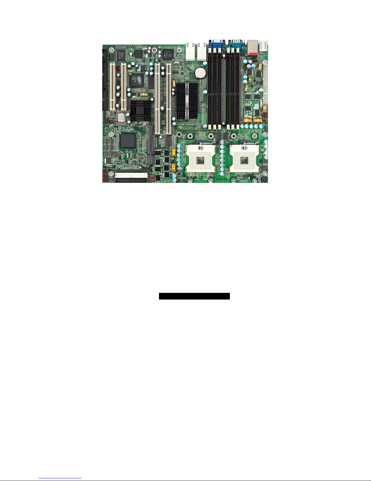
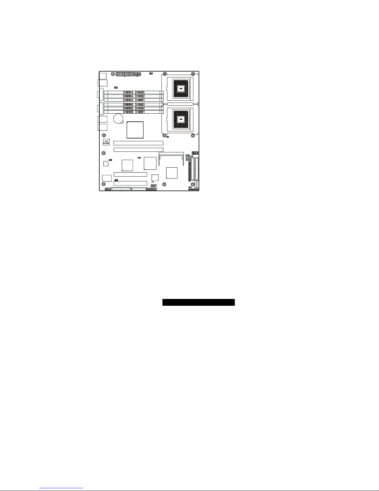
2.1 – Board Image
The following is an image of the Tiger i7501R S2735.
The above photograph is purely representative. Due to engineering updates and
new board revisions, certain components may change and or be repositioned. The
picture above may or may not look exactly like the board you received.
The following page will shows the S2735 Block Diagram. You can see the PCI-X/PCI bus
assignment.

9
http://www.TYAN.com
2.2 – Block Diagram of S2735
VRM
GALLATIN OR
PRESTONIA
PLUMAS
MCH
Intel 82801ER
ICH5R
DDR
P64H2
SUPER-I/O
W83627HF
PRIMARY
IDE CONN
HOST BUS 400 or 533
MEM CNTRL AND DATA
BUS #02
HI 2.0
BUS # 01
BUS # 00
DDR
DDR
DDR
DDR
DDR
ICH3_PIRQ#A
BUS #03
133MHz OR
100MHz PCI-X
BUS #04
133MHz OR
100MHz PCI-X
GBIT LAN
82546
RJ45 RJ45
SECONDARY
IDE CONN
SATA
CONN
USB
CONN
PRINTER
PORT
SERIAL
PORT
SERIAL
PORT
KBD
PORT
FLOPPY
CONN
BIOS
4MB
SERVER
MGMT
CONN
Winbond
83782D or
ADM1027
ATI
Rage XL
10/100
LAN
82551
8MB DISPLAY
MEMORY
RJ45
CRT
CONN
MEM CNTRL AND DATA
HI 1.5
DDR B DIMMS
DDR A DIMMS
SLOT# 1
*Option
SLOT# 2
BUS A
BUS B
SLOT# 4
SLOT# 3
LPC BUS
FIRMWARE HUB
SO DIMM
SLOT#1
GALLATIN OR
PRESTONIA
PCI 32/33MHz
The following page includes details on the vital components of this motherboard.
10
http://www.TYAN.com
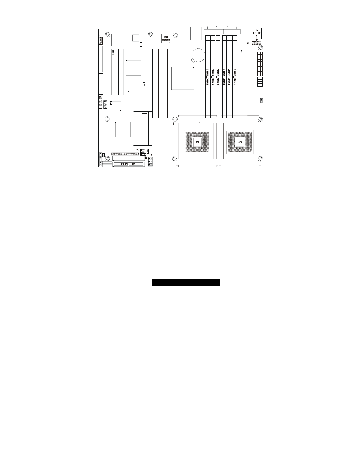
2.3 – Board Parts, Jumpers, and Connectors
S2735
1
J5
USB1
J7 (COM1)
J11 (VGA)
FAN1
CPU1_FAN
J3
J14
LAN3
BIOS
Intel
ICH5R
SATA2
SATA1
FDD J37
SEC-IDE J13
J39
FRONT
PAN EL
1
Winbond
W83627HF
PCI4
PCI1
J36
USB (Bottom)
LAN1 (Top)Optional
J15
LAN2
ATI
RAGE XL
LPT1
USB2
J34
SMDC J29
COM2
BT1
PCI 2
Intel
E7501
Intel
82551
PCI3
P64H2
SEC-IDE J13SEC-IDE J13SEC-IDE J13SEC-IDE J13
J1
J26
SO_DIMM
1
FAN4 CPU2_FAN
1
FAN7
1
J32
FAN6
1
FAN2
1
FAN3
CMOS
J33
J25
1
J23
1
J24
1
J22
1
J31
1
1
J21
J16
1
CPU1CPU2
1
1
FAN8
1
FAN5
1
FAN9
1
1
J43
This jumper diagram is only a representation of the latest board revision available
at the time of publishing. The board you receive may or may not look exactly like
the above diagram.
11
http://www.TYAN.com
2.4 – Jumper Settings
Jumper Function Settings
J16 Force 400MHz FSB instead of 533MHz FSB Header Page 11
J21 PCI-X A (PCI1) Speed Header Page 12
J22 10/100 Ethernet LAN1 LED Header Page 12
J23 Gigabit Ethernet LAN2 (J15) LED Header Page 12
J24 Gigabit Ethernet LAN3 (J14) LED Header Page 12
J25 Buzzer (System Speaker) Page 13
J26 SO-DIMM Socket Page 13
J29
SMDC (System Management Daughter Card)
Connector
Page 13
J31 Hard Disk Activity LED External Input Page 14
J33 Clear CMOS Jumper Page 14
J34 Front USB Header Page 15
J36 COM2 Header Page 15
J39 Front Panel Connector Page 16
J43 PCI-X B (PCI2) Speed Header Page 16
2.5 – Jumper Definitions
Jumper Example
Jumper OFF – open
Jumper ON – closed
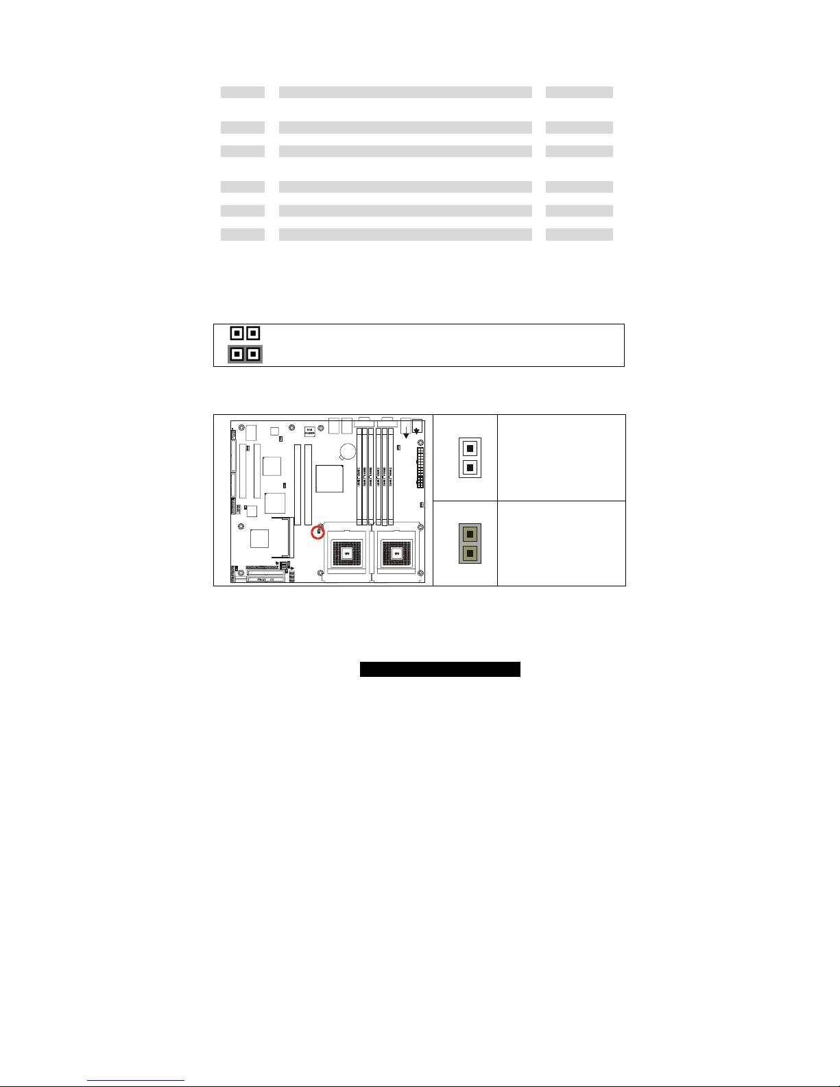
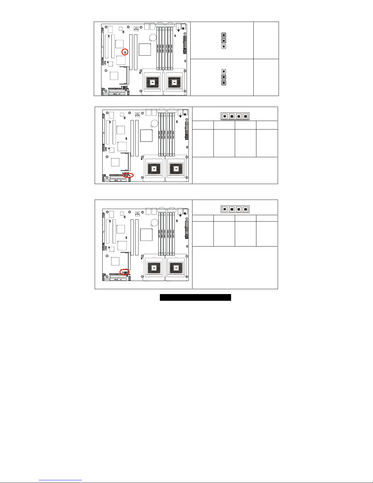
2.6 – Force 400MHz FSB instead of 533MHz FSB Header (J16)
1
OPEN:
533MHz FSB
(4x 133MHz)
S2735
1
J5
USB1
J7 (COM1)J11 (VGA)
FAN1
CPU1_FAN
J3
J14
LAN3
BIOS
Intel
ICH5R
SATA2
SATA1
FDD J37
SEC-IDE J13
J39
FRONT
PANEL
1
Winbond
W83627HF
PCI4
PCI1
J36
USB (Bottom)
LAN1 (Top)Optional
KB(Bottom)
Mouse(Top)
J4
KB / MS
J15
LAN2
ATI
RAGE XL
LPT1
USB2
J34
SMDC J29
COM2
BT1
PCI 2
Intel
E7501
Intel
82551
PCI3
P64H2
SEC-IDE J13SEC-IDE J13SEC-IDE J13SEC-IDE J13
J1
J26
SO_DIMM
1
FAN4 CPU2_FAN
1
FAN7
1
J32
FAN6
1
FAN2
1
FAN3
CMOS
J33
J25
1
J23
1
J24
1
J22
1
J31
1
1
J21
J16
1
CPU1CPU2
1
1
FAN8
1
FAN5
1
FAN9
1
1
J43
1
CLOSED:
Force 400MHz FSB
(4x 100MHz)
12
http://www.TYAN.com
2.7 – PCI-X A (PCI1) Speed Header (J21)
3
1
100MHz
S2735
1
J5
USB1
J7 (COM1)J11 (VG A)
FAN1
CPU1_FAN
J3
J14
LAN3
BIOS
Intel
ICH5R
SATA2
SATA1
FDD J37
SEC-IDE J13
J39
FRONT
PANEL
1
Winbond
W83627HF
PCI4
PCI1
J36
USB (Bottom)
LAN1 (Top)Optional
KB(Bottom)
Mouse(Top)
J4
KB / MS
J15
LAN2
ATI
RAGE XL
LPT1
USB2
J34
SMDC J2 9
COM2
BT1
PCI 2
Intel
E7501
Intel
82551
PCI3
P64H2
SEC-IDE J13SEC-IDE J13SEC-IDE J13SEC-IDE J13
J1
J26
SO_DIMM
1
FAN4 CPU2_FAN
1
FAN7
1
J32
FAN6
1
FAN2
1
FAN3
CMOS
J33
J25
1
J23
1
J24
1
J22
1
J31
1
1
J21
J16
1
CPU1CPU2
1
1
FAN8
1
FAN5
1
FAN9
1
1
J43
3
1
133MHz
(Default)
2.8 – 10/100 Ethernet LAN1 LED Header (J22)
41
Pin_1 Pin_2 Pin_3 Pin_4
Yellow +
Yellow -
Green +
Green -
S2735
1
J5
USB1
J7 (COM1)J11 (VGA)
FAN1
CPU1_FAN
J3
J14
LAN3
BIOS
Intel
ICH5R
SATA2
SATA1
FDD J37
SEC-IDE J13
J39
FRONT
PANEL
1
Winbond
W83627HF
PCI4
PCI1
J36
USB (Bottom)
LAN1 (Top)Optional
KB(Bottom)
Mouse(Top)
J4
KB / MS
J15
LAN2
ATI
RAGE XL
LPT1
USB2
J34
SMDC J29
COM2
BT1
PCI 2
Intel
E7501
Intel
82551
PCI3
P64H2
SEC-IDE J13SEC-IDE J13SEC-IDE J13SEC-IDE J13
J1
J26
SO_DIMM
1
FAN4 CPU2_FAN
1
FAN7
1
J32
FAN6
1
FAN2
1
FAN3
CMOS
J33
J25
1
J23
1
J24
1
J22
1
J31
1
1
J21
J16
1
CPU1CPU2
1
1
FAN8
1
FAN5
1
FAN9
1
1
J43
No LED = 10Mb link
Green LED flashing= 10Mb activity
Yellow LED solid= 100Mb link
Both LED flashing= 100Mb activity
2.9 – Gigabit Ethernet LAN2 (J15) LED Header (J23) and
Gigabit Ethernet LAN3 (J14) LED Header (J24)
41
Pin_1 Pin_2 Pin_3 Pin_4
Yellow +
Yellow -
Green +
Green -
S2735
1
J5
USB1
J7 (COM1)J11 (VGA)
FAN1
CPU1_FAN
J3
J14
LAN3
BIOS
Intel
ICH5R
SATA2
SATA1
FDD J37
SEC-IDE J13
J39
FRONT
PANEL
1
Winbond
W83627HF
PCI4
PCI1
J36
USB (Bottom)
LAN1 (Top)Optional
KB(Bottom)
Mouse(Top)
J4
KB / MS
J15
LAN2
ATI
RAGE XL
LPT1
USB2
J34
SMDC J29
COM2
BT1
PCI 2
Intel
E7501
Intel
82551
PCI3
P64H2
SEC-IDE J13SEC-IDE J13SEC-IDE J13SEC-IDE J13
J1
J26
SO_DIMM
1
FAN4 CPU2_FAN
1
FAN7
1
J32
FAN6
1
FAN2
1
FAN3
CMOS
J33
J25
1
J23
1
J24
1
J22
1
J31
1
1
J21
J16
1
CPU1CPU2
1
1
FAN8
1
FAN5
1
FAN9
1
1
J43
Green LED solid= 10Mb link
Green LED flashing= 10Mb activity
Yellow LED solid= 100Mb link
Yellow LED flashing= 100Mb activity
Both LED Solid= Gigabit link
Both LED flashing= Gigabit activity
13
http://www.TYAN.com
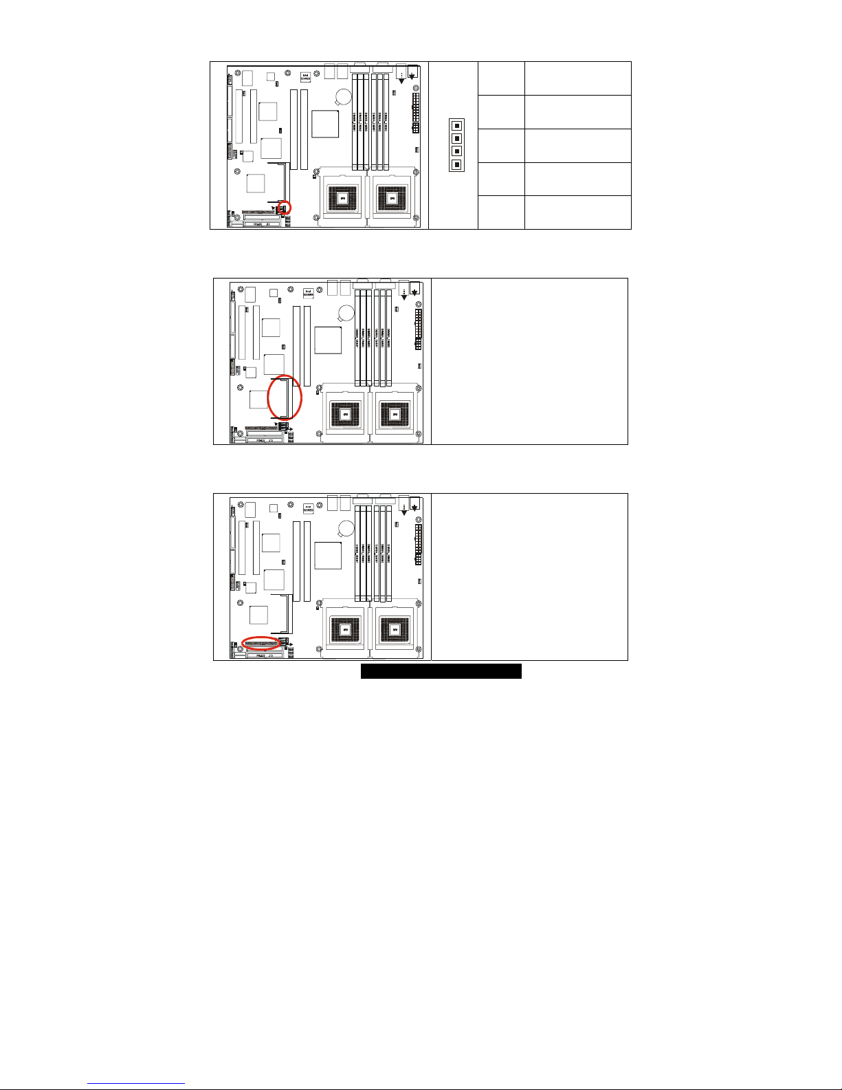
2.10 – Buzzer (System Speaker) (J25)
Pin # Signal Description
4 Speak
3 NC
2 NC
S2735
1
J5
USB1
J7 (COM1)J11 (VG A)
FAN1
CPU1_FAN
J3
J14
LAN3
BIOS
Intel
ICH5R
SATA2
SATA1
FDD J37
SEC-IDE J13
J39
FRONT
PANEL
1
Winbond
W83627HF
PCI4
PCI1
J36
USB (Bottom)
LAN1 (Top)Optional
KB(Bottom)
Mouse(Top)
J4
KB / MS
J15
LAN2
ATI
RAGE XL
LPT1
USB2
J34
SMDC J2 9
COM2
BT1
PCI 2
Intel
E7501
Intel
82551
PCI3
P64H2
SEC-IDE J13SEC-IDE J13SEC-IDE J13SEC-IDE J13
J1
J26
SO_DIMM
1
FAN4 CPU2_FAN
1
FAN7
1
J32
FAN6
1
FAN2
1
FAN3
CMOS
J33
J25
1
J23
1
J24
1
J22
1
J31
1
1
J21
J16
1
CPU1CPU2
1
1
FAN8
1
FAN5
1
FAN9
1
1
J43
1
4
1 VCC
2.11 – SO-DIMM Socket (J26)
S2735
1
J5
USB1
J7 (COM1)J11 (VG A)
FAN1
CPU1_FAN
J3
J14
LAN3
BIOS
Intel
ICH5R
SATA2
SATA1
FDD J37
SEC-IDE J13
J39
FRONT
PANEL
1
Winbond
W83627HF
PCI4
PCI1
J36
USB (Bottom)
LAN1 (Top)Optional
KB(Bottom)
Mouse(Top)
J4
KB / MS
J15
LAN2
ATI
RAGE XL
LPT1
USB2
J34
SMDC J2 9
COM2
BT1
PCI 2
Intel
E7501
Intel
82551
PCI3
P64H2
SEC-IDE J13SEC-IDE J13SEC-IDE J13SEC-IDE J13
J1
J26
SO_DIMM
1
FAN4 CPU2_FAN
1
FAN7
1
J32
FAN6
1
FAN2
1
FAN3
CMOS
J33
J25
1
J23
1
J24
1
J22
1
J31
1
1
J21
J16
1
CPU1CPU2
1
1
FAN8
1
FAN5
1
FAN9
1
1
J43
Connect SCSI Daughter Card
Compatible with Tyan M7902 (Ref.
Appendix IV)
2.12 – SMDC (System Management Daughter Card) Connector (J29)
S2735
1
J5
USB1
J7 (COM1)J11 (VG A)
FAN1
CPU1_FAN
J3
J14
LAN3
BIOS
Intel
ICH5R
SATA2
SATA1
FDD J37
SEC-IDE J13
J39
FRONT
PANEL
1
Winbond
W83627HF
PCI4
PCI1
J36
USB (Bottom)
LAN1 (Top)Optional
KB(Bottom)
Mouse(Top)
J4
KB / MS
J15
LAN2
ATI
RAGE XL
LPT1
USB2
J34
SMDC J2 9
COM2
BT1
PCI 2
Intel
E7501
Intel
82551
PCI3
P64H2
SEC-IDE J13SEC-IDE J13SEC-IDE J13SEC-IDE J13
J1
J26
SO_DIMM
1
FAN4 CPU2_FAN
1
FAN7
1
J32
FAN6
1
FAN2
1
FAN3
CMOS
J33
J25
1
J23
1
J24
1
J22
1
J31
1
1
J21
J16
1
CPU1CPU2
1
1
FAN8
1
FAN5
1
FAN9
1
1
J43
Connect Server Management Daughter
Card (SMDC) (Ref. Appendix II)
Compatible with Tyan M3289 (SMDC)
14
http://www.TYAN.com
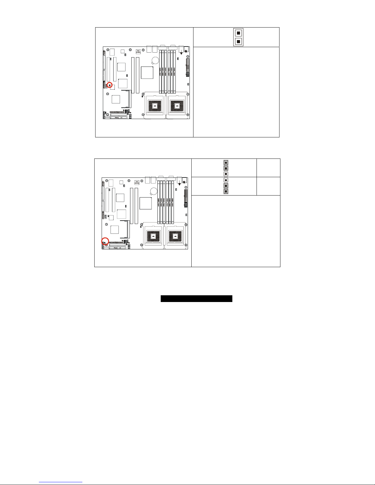
2.13 – Hard Disk Activity LED External Input (J31)
1
S2735
1
J5
USB1
J7 (COM1)J11 (VGA)
FAN1
CPU1_FAN
J3
J14
LAN3
BIOS
Intel
ICH5R
SATA2
SATA1
FDD J37
SEC-IDE J13
J39
FRONT
PANEL
1
Winbond
W83627HF
PCI4
PCI1
J36
USB (Bottom)
LAN1 (Top)Optional
KB(Bottom)
Mouse(Top)
J4
KB / MS
J15
LAN2
ATI
RAGE XL
LPT1
USB2
J34
SMDC J29
COM2
BT1
PCI 2
Intel
E7501
Intel
82551
PCI3
P64H2
SEC-IDE J13SEC-IDE J13SEC-IDE J13SEC-IDE J13
J1
J26
SO_DIMM
1
FAN4 CPU2_FAN
1
FAN7
1
J32
FAN6
1
FAN2
1
FAN3
CMOS
J33
J25
1
J23
1
J24
1
J22
1
J31
1
1
J21
J16
1
CPU1CPU2
1
1
FAN8
1
FAN5
1
FAN9
1
1
J43
J31 is an LED INPUT. The idea is to
run a wire from the activity LED output
header of any plug-in HD controller
card (e.g. a RAID card) to the
motherboard, so that the card's LED
can be "combined " with the IDE and
SCSI activity indicators on the
motherboard and then driven to the
J39 HD LED output. In other words,
when a card's LED lights up, so will
the front-panel hard-disk activity
indicator. This is useful for chassis that
have only a single LED to indicate HD
activity from multiple controller
sources. (Pin 1 = negative terminal of
the add-on card's LED header, Pin 2 =
do not connect.)
2.14 – Clear CMOS Jumper (J33)
3
1
Default
3
1
Clear
S2735
1
J5
USB1
J7 (COM1)J11 (VG A)
FAN1
CPU1_FAN
J3
J14
LAN3
BIOS
Intel
ICH5R
SATA2
SATA1
FDD J37
SEC-IDE J13
J39
FRONT
PANEL
1
Winbond
W83627HF
PCI4
PCI1
J36
USB (Bottom)
LAN1 (Top)Optional
KB(Bottom)
Mouse(Top)
J4
KB / MS
J15
LAN2
ATI
RAGE XL
LPT1
USB2
J34
SMDC J2 9
COM2
BT1
PCI 2
Intel
E7501
Intel
82551
PCI3
P64H2
SEC-IDE J13SEC-IDE J13SEC-IDE J13SEC-IDE J13
J1
J26
SO_DIMM
1
FAN4 CPU2_FAN
1
FAN7
1
J32
FAN6
1
FAN2
1
FAN3
CMOS
J33
J25
1
J23
1
J24
1
J22
1
J31
1
1
J21
J16
1
CPU1CPU2
1
1
FAN8
1
FAN5
1
FAN9
1
1
J43
You can reset the CMOS settings by
using this jumper if you have forgotten
your system/setup password or need to
clear system BIOS setting.
- Power off system and disconnect
both power connectors from the
motherboard
- Use jumper cap to close Pin_2 and
Pin_3 for several seconds to Clear
CMOS
- Put jumper cap back to Pin_1 and
Pin_2 (default setting)
Reconnect power & power on system

15
http://www.TYAN.com
2.15 – Front USB Header (J34)
1
9
2
10
Signal
Description
Pin Pin
Signal
Description
+5V 1 2 +5V
Data - 3 4 Data -
Data + 5 6 Data +
GND 7 8 GND
S2735
1
J5
USB1
J7 (COM1)J11 (VGA)
FAN1
CPU1_FAN
J3
J14
LAN3
BIOS
Intel
ICH5R
SATA2
SATA1
FDD J37
SEC-IDE J13
J39
FRONT
PANEL
1
Winbond
W83627HF
PCI4
PCI1
J36
USB (Bottom)
LAN1 (Top)Optional
KB(Bottom)
Mouse(Top)
J4
KB / MS
J15
LAN2
ATI
RAGE XL
LPT1
USB2
J34
SMDC J29
COM2
BT1
PCI 2
Intel
E7501
Intel
82551
PCI3
P64H2
SEC-IDE J13SEC-IDE J13SEC-IDE J13SEC-IDE J13
J1
J26
SO_DIMM
1
FAN4 CP U2_FA N
1
FAN7
1
J32
FAN6
1
FAN2
1
FAN3
CMOS
J33
J25
1
J23
1
J24
1
J22
1
J31
1
1
J21
J16
1
CPU1CPU2
1
1
FAN8
1
FAN5
1
FAN9
1
1
J43
GND 9 10 GND
2.16 – COM2 Header (J36)
1
9
2
10
Signal
Description
Pin Pin
Signal
Description
DCD
(Data
Carrier
Detect)
1 2
DSR (DataSet-Ready)
RX
(ReceiveData)
3 4
RTS
(Request-toSend)
TX
(TransferData)
5 6
CTS (Clearto-Send)
DTR (DataTerminalReady)
7 8
RI (RingIndicator)
S2735
1
J5
USB1
J7 (COM1)J11 (VGA)
FAN1
CPU1_FAN
J3
J14
LAN3
BIOS
Intel
ICH5R
SATA2
SATA1
FDD J37
SEC-IDE J13
J39
FRONT
PANEL
1
Winbond
W83627HF
PCI4
PCI1
J36
USB (Bottom)
LAN1 (Top)Optional
KB(Bottom)
Mouse(Top)
J4
KB / MS
J15
LAN2
ATI
RAGE XL
LPT1
USB2
J34
SMDC J2 9
COM2
BT1
PCI 2
Intel
E7501
Intel
82551
PCI3
P64H2
SEC-IDE J13SEC-IDE J13SEC-IDE J13SEC-IDE J13
J1
J26
SO_DIMM
1
FAN4 CPU2_FAN
1
FAN7
1
J32
FAN6
1
FAN2
1
FAN3
CMOS
J33
J25
1
J23
1
J24
1
J22
1
J31
1
1
J21
J16
1
CPU1CPU2
1
1
FAN8
1
FAN5
1
FAN9
1
1
J43
GND
(Ground)
9 10 NC/KEY
16
http://www.TYAN.com
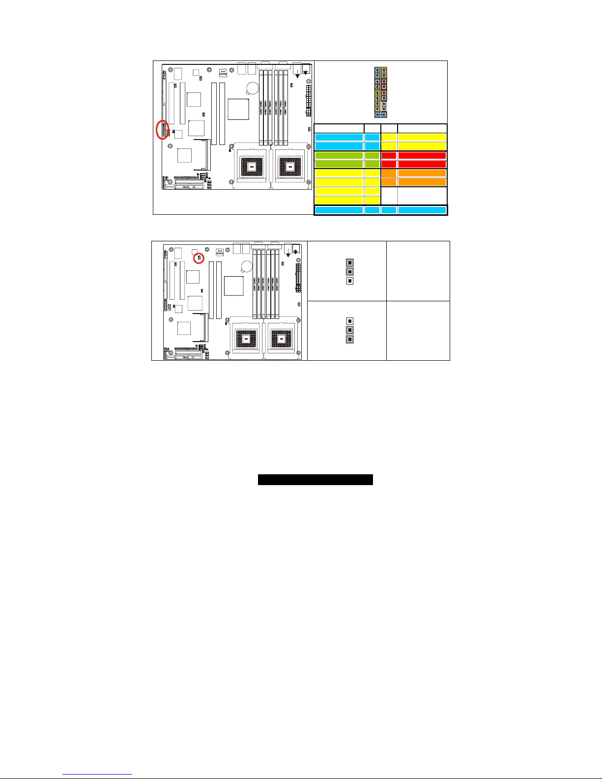
2.17 – Front Panel Connector (J39)
Your chassis will usually come with connectors to install onto the motherboard, such as
HD and Power LEDs. The Front Panel Connector (J39) has been implemented for such
purposes.
1 2
17 18
Function Pin Pin Function
HDD_LED+ 1 2 Power_LED+
HDD_LED- 3 4 Power LED-
GND 5 6 PWR+
Reset+ 7 8 GND
+5V 9
10
Sleep+
IRRX 11 12 GND
GND 13 14 NC
IRTX 15 16 NC
S2735
1
J5
USB1
J7 (COM1)J11 (VGA)
FAN1
CPU1_FAN
J3
J14
LAN3
BIOS
Intel
ICH5R
SATA2
SATA1
FDD J37
SEC-IDE J13
J39
FRONT
PANEL
1
Winbond
W83627HF
PCI4
PCI1
J36
USB (Bottom)
LAN1 (Top)Optional
KB(Bottom)
Mouse(Top)
J4
KB / MS
J15
LAN2
ATI
RAGE XL
LPT1
USB2
J34
SMDC J29
COM2
BT1
PCI 2
Intel
E7501
Intel
82551
PCI3
P64H2
SEC-IDE J13SEC-IDE J13SEC-IDE J13SEC-ID E J13
J1
J26
SO_DIMM
1
FAN4 CPU2_FAN
1
FAN7
1
J32
FAN6
1
FAN2
1
FAN3
CMOS
J33
J25
1
J23
1
J24
1
J22
1
J31
1
1
J21
J16
1
CPU1CPU2
1
1
FAN8
1
FAN5
1
FAN9
1
1
J43
INTRU+ 17 18 INTRU-
2.18 – PCI-X B (PCI2) Speed Header (J43)
3
1
100MHz
(Default)
S2735
1
J5
USB1
J7 (COM1)J11 (VG A)
FAN1
CPU1_FAN
J3
J14
LAN3
BIOS
Intel
ICH5R
SATA2
SATA1
FDD J37
SEC-IDE J13
J39
FRONT
PANEL
1
Winbond
W83627HF
PCI4
PCI1
J36
USB (Bottom)
LAN1 (Top)Optional
KB(Bottom)
Mouse(Top)
J4
KB / MS
J15
LAN2
ATI
RAGE XL
LPT1
USB2
J34
SMDC J2 9
COM2
BT1
PCI 2
Intel
E7501
Intel
82551
PCI3
P64H2
SEC-IDE J13SEC-IDE J13SEC-IDE J13SEC-IDE J13
J1
J26
SO_DIMM
1
FAN4 CPU2_FAN
1
FAN7
1
J32
FAN6
1
FAN2
1
FAN3
CMOS
J33
J25
1
J23
1
J24
1
J22
1
J31
1
1
J21
J16
1
CPU1CPU2
1
1
FAN8
1
FAN5
1
FAN9
1
1
J43
3
1
133MHz
(Gigabit only)
17
http://www.TYAN.com
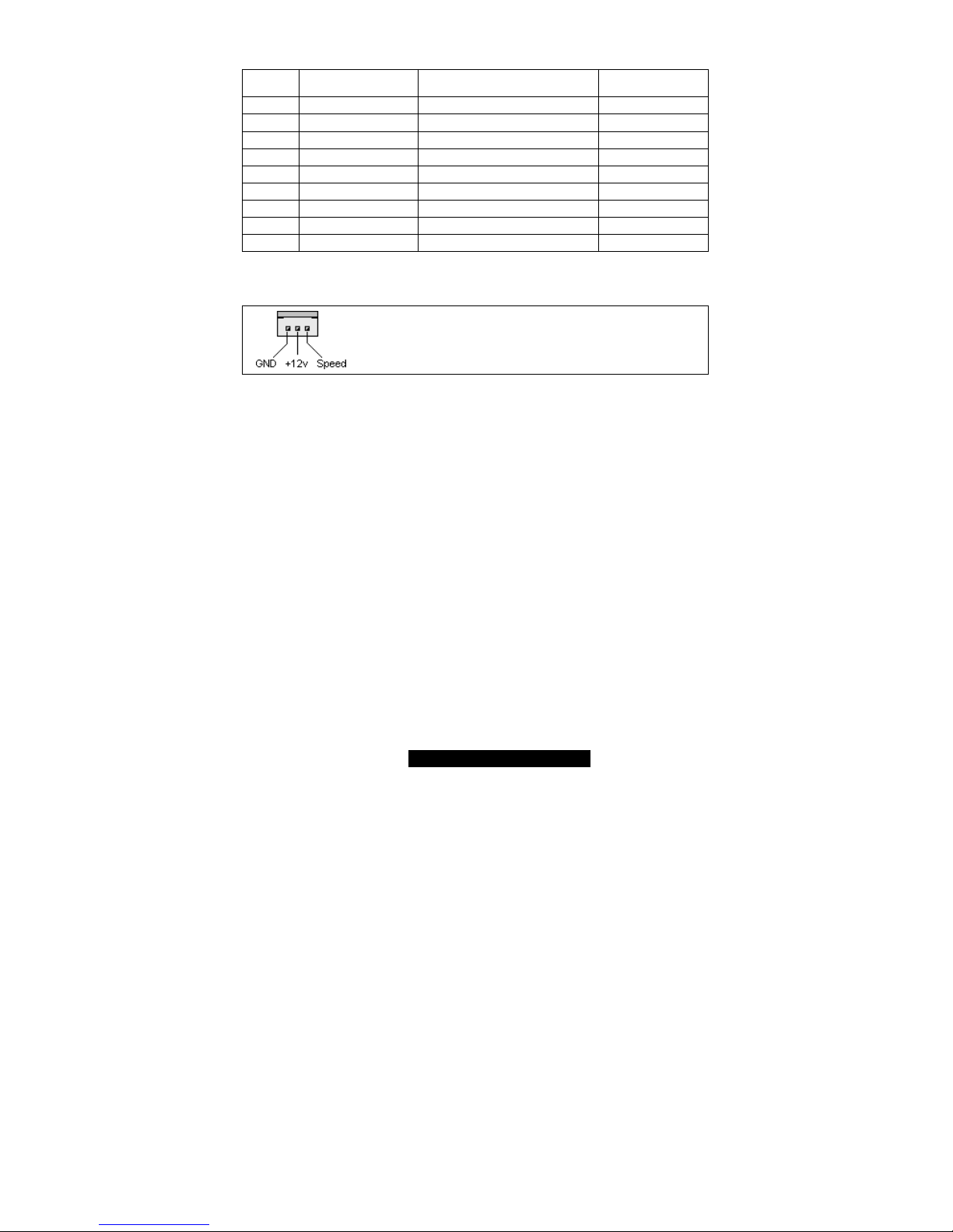
2.19
– Fan Header Information
Fan # Fan Description Functions
Amp Rated
(Maximum)
FAN1 CPU 1 Fan RPM Read and controlled 1.5A
FAN2 Chassis Fan RPM Read 1.2A
FAN3 Chassis Fan RPM Read 1.2A
FAN4 CPU 2 Fan RPM Read and controlled 1.5A
FAN5 Chassis Fan RPM Read and controlled 1.2A
FAN6 Chassis Fan None 2A
FAN7 Chassis Fan RPM Read 1.2A
FAN8 Chassis Fan None 2A
FAN9 Chassis Fan None 2A
FAN connectors
Use these headers to connect cooling fans, both chassis and
processor fans, to your motherboard. Cooling fans help keep
the system more stable and operating reliably for its product life.
+12V fans supported
18
http://www.TYAN.com
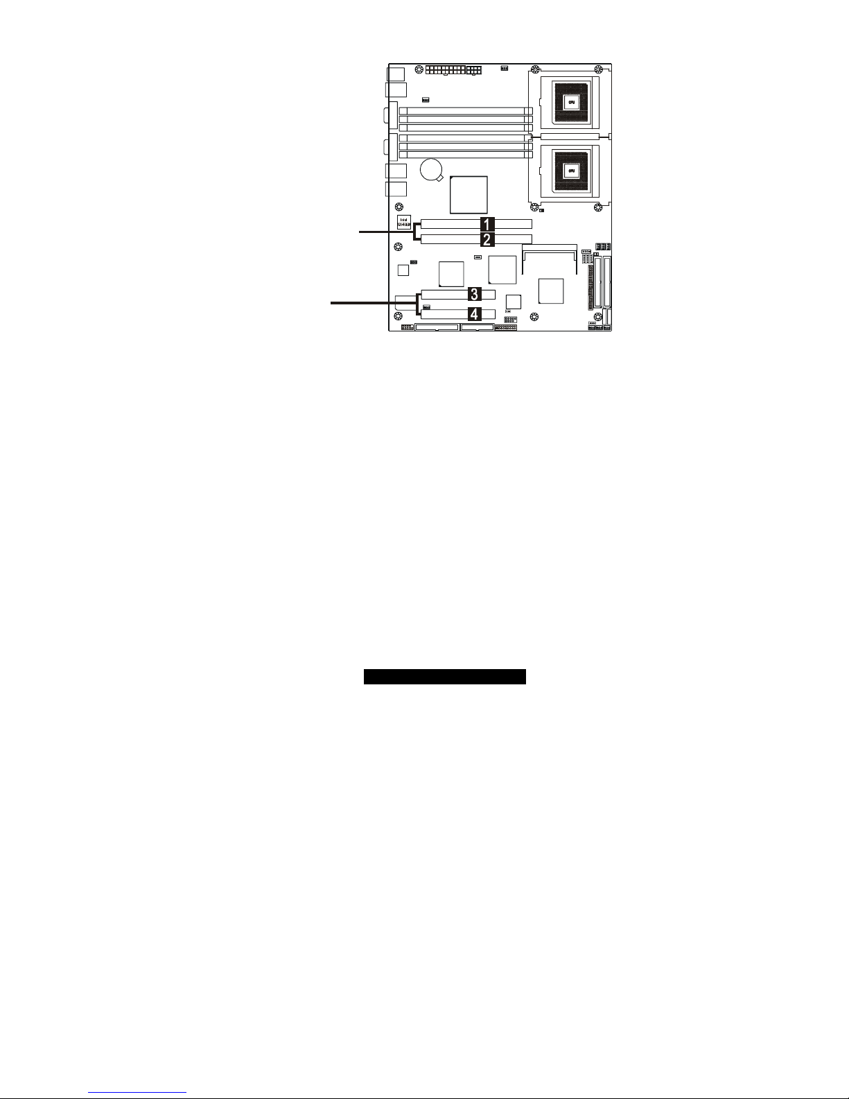
2.20 – PCI Setup
BIOS
Intel
ICH5R
Winbond
W83627HF
A
TI
RAGE XL
Intel
82551
P64H2
S2735
Intel
E7501
CPU1
CPU2
PCI-X slots
PCI slots
Intel 82870P2 64-bit PCI-X/PCI Controller (P64H2) provides two independent 64-bit
133/100/66MHz PCI-X / PCI bus channels:
First channel:
o Slot (1, 2): 64-bit 133/100/66MHz (3.3V) PCI-X / PCI
3.3 volt or universal PCI-X/PCI cards are accepted
Second channel:
o Onboard Intel’s 82546EB 64-bit PCI-X dual gigabit Ethernet
controller and SCSI add-on option
Two RJ45 connectors
One SO-DIMM connector
Optional Intel’s 82545EM single channel gigabit Ethernet
controller
Intel 82801EB (ICH5) or 82801ER (ICH5R) provides one 32-bit 33MHz (5V) PCI bus:
o Slot (3, 4): 32-bit 33MHz (5V) PCI
5 volt and universal cards are accepted

19
http://www.TYAN.com
2.21 – Mounting the Motherboard
Before installing your motherboard, make sure your chassis has the necessary
motherboard support studs installed. These studs are usually metal and are gold in color.
Usually, the chassis manufacturer will pre-install the support studs. If you’re unsure of
stud placement, simply lay the motherboard inside the chassis and align the screw holes
of the motherboard to the studs inside the case. If there are any studs missing, you will
know right away since the motherboard will not be able to be securely installed.
Some chassis’ include plastic studs instead of metal. Although the plastic studs are
usable, Tyan recommends using metal studs with screws that will fasten the motherboard
more securely in place.
Below is a chart detailing what the most common motherboard studs look like and how
they should be installed.
TIP: Use metal studs if possible, as they hold the motherboard into place more securely
than plastic standoffs.
20
http://www.TYAN.com
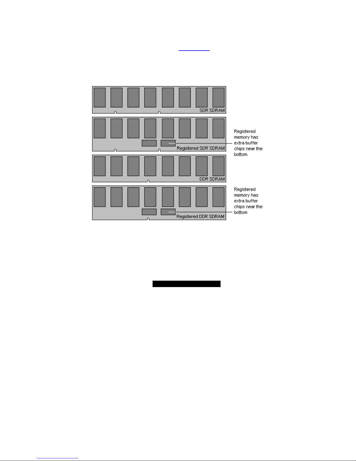
2.22 – Installing the Memory
Before attempting to install any memory, make sure that the memory you have is
compatible with the motherboard as well as the processor. Critically important is whether
you’re using the recommended memory for the current board you have. For this
information, please check Tyan’s web site at: www.tyan.com
The following diagram shows the types of RAM modules you may encounter depending
on your board:
21
http://www.TYAN.com
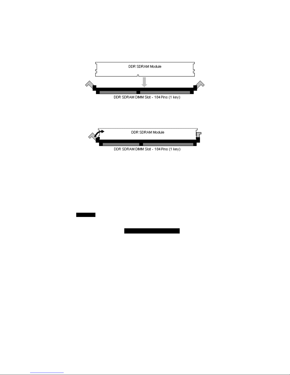
Memory Installation Procedure
The Tiger i7501R S2735 requires that memory modules be installed in pairs. Please
refer to the next page for exact details on installing memory modules correctly.
When installing memory modules, make sure the modules align properly with the memory
socket. There should be keys (small indents) on your memory modules that fit according
to the keys in the memory socket. DDR modules and sockets have only one key, which is
slightly near the center of the module/socket. The method of installing memory modules is
detailed in the following diagrams.
Once the memory modules are firmly seated in the socket, two clamps on either side will
close and secure the module into the socket. Sometimes you may need to close the
clamps manually.
To remove the memory module, simply push the clamps outwards until the memory
module pops up. Then simply remove the module.
TIP: When installing memory, a module may require a considerable amount of force to
seat properly, although this is very rare. To avoid bending and damaging your
motherboard, place it on its anti-static bag and onto a flat surface, and then proceed with
memory installation.
NOTE
YOU MUST unplug the power connector to the motherboard before
performing system hardware changes, to avoid damaging the board or
expansion device.
22
http://www.TYAN.com
Memory Pair Installation
When installing DIMM modules, you must install the first two memory modules in
DIMMA_DIMM1 and DIMMB_DIMM1.
Both modules must be the same in both size and density. Modules must also use the
same chip configuration, as in each module that is installed must physically have the
same number of memory chips on them.
All memory sockets must be populated by the same memory type, either x4 modules or
x8 you cannot mix and match x4 and x8 modules together.
BIOS
Intel
ICH5R
Winbond
W83627HF
ATI
RAGE XL
Intel
82551
P64H2
S2735
Intel
E7501
CPU1
CPU2
Points to remember:
• At least two Registered ECC DDR SDRAM modules must be installed for the
system to turn on and POST (Power On Self Test). Single Channel memory
support is not currently available. Please check Tyan’s website for updates on
this topic.
• When installing modules, install them in this order: DIMMA_DIMM1,
DIMMB_DIMM1, DIMMA_DIMM2, DIMMB_DIMM2, etc.
• 128MB, 256MB, 512MB, 1GB, and 2GB Registered ECC PC2100/PC1600
DDR SDRAM memory modules are supported in x4 or x8 configuration.
• The Tiger i7501R S2735 supports up to 12GB of memory with 2GB (X4)
registered DDR modules.
• Use ONLY x8 OR x4 type memory modules. Mixing memory types may affect
stability.

23
http://www.TYAN.com
• RAM chips are organized as x4 bits or x8 bits. On a memory module you’re just
lining all these chips up in parallel so you have a 64bit wide data bus. All
512MB modules are made using 16 pieces of either 64Mbit x4, or 32Mbit x8. If
you use sixteen x8 chips you would get a 128bit data bus, so it has to be split
into two separate banks. Each with 64bit bus. That’s why 512MB modules
based on x8 chips are dual bank. To build 256MB modules you can either use
sixteen 32Mx4 chips, or eight 32Mx8 chips. But you can’t build a 256MB
module using 64Mx4 chips. To build 1GB modules you have to use thirty-two
64Mx4 chips. Two 64Mx4 chips are stacked on top of each other with a lead
frame in between. Stacking basically converts two 64Mx4 chips into one
128Mx4 chip or one 64Mx8 chip. Then you stick 16 stacks onto a PCB.
Stacking also saves real estate, so you can fit more chips onto a shorter PCB
and keep trace lengths in spec.
If you are still unsure whether you are using x4 or x8 memory you can research the
memory chip by the SDRAM part numbers, or go to http://www.google.com
and
search for jedec 21-c 4.20.4.
24
http://www.TYAN.com
2.23 – Installing the Processor and Heatsink
Your Tiger i7501R S2735 supports the latest processor technologies from Intel. Check the
following page on TYAN’s website for latest processor support:
http://www.Tyan.com
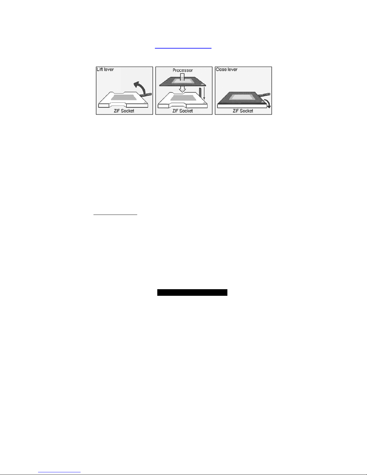
The following diagrams will detail how to install your processor(s):
The processors you choose to use may not look exactly like the one pictured above, nor
will the socket look exactly the same. The diagram is provided as a visual guide to help
you install socket processors.
1. Lift the lever on the socket until it is approximately 130
o
or as far back as
possible to the socket.
2. Align the processor with the socket. There are keys underneath the processor
just like on memory modules to ensure that they insert the correct way.
3. Seat the processor firmly into the socket by gently pressing down until the
processor sits flush with the socket.
4. Place the socket lever back down until it snaps into place.
5. Your processor is installed.
6. Repeat these steps for the second processor if you are using two processors.
NOTE: If using only one CPU, it must be installed in CPU1 socket.
Heatsink Installation
After you are done installing the processor(s), you should proceed to installing their
heatsinks. Heatsinks will ensure that the processors do not overheat and continue to
operate at maximum performance for as long as you own them. Overheated processors
may damage the motherboard.
Because there are many different types of heatsinks available from many different
manufacturers, a lot of them have their own method of installation. For the safest method
of installation and information on choosing the appropriate heatsink, please refer to Intel’s
website at http://www.intel.com.
25
http://www.TYAN.com
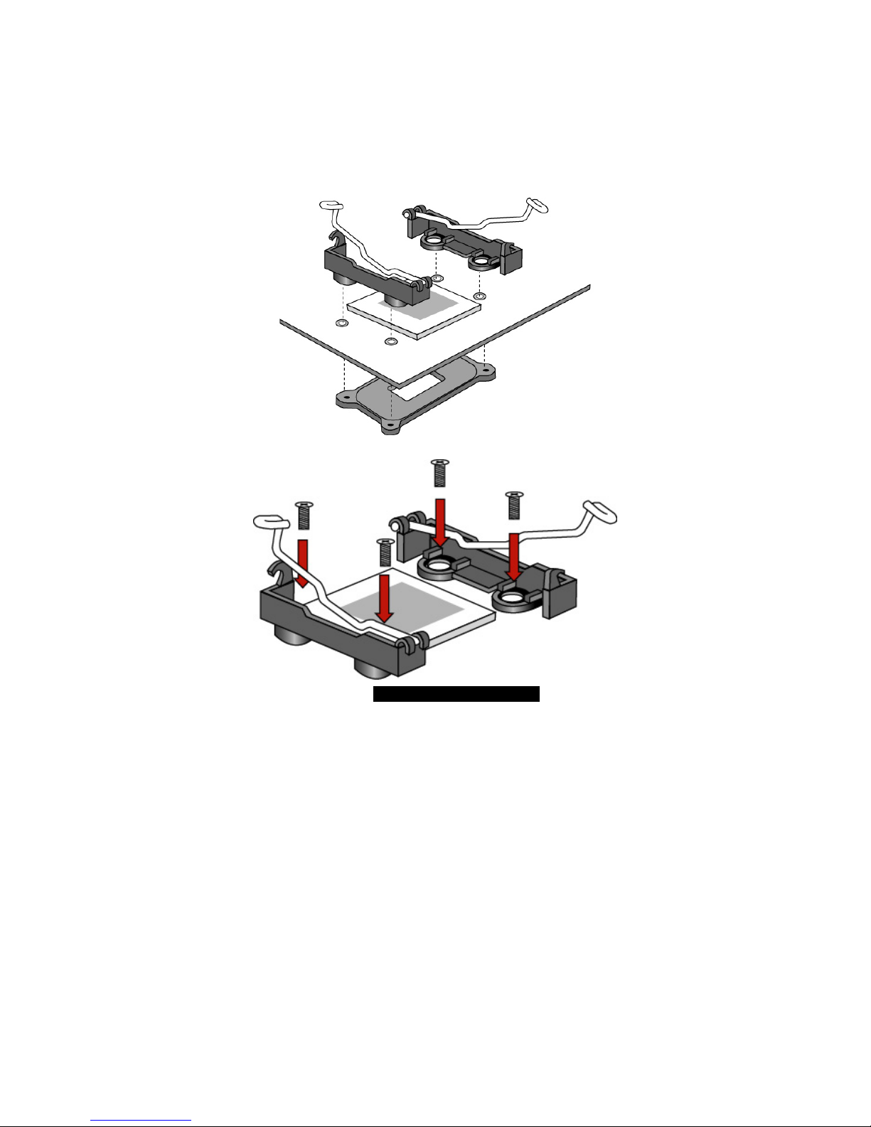
2.24 – Installing CPU Back-plates and retention modules
The following diagrams will illustrate how to install the included heatsink retention
modules and CPU back-plates. You should have: two back-plates and 9 screws. (Four
screws for each plate and one spare screw.)
NOTE: The back-plates must be installed prior to installing the motherboard into a chassis.
(Certain 1U chassis may not require the back-plates.)
1) Align the heatsink mounting bracket to the holes around the processor socket
2) Insert screws into bracket holes
26
http://www.TYAN.com
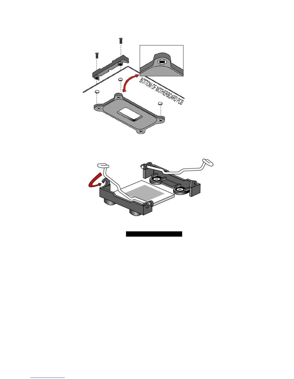
3) Screws should pass through bracket holes and through the motherboard.
4) Tighten screws into the CPU back-plates.
NOTE: The hexagonal nut MUST be on the viewable side of the CPU backplate as shown below!
5) After installing the CPU, seat the heatsink between brackets on processor
6) Attach heatsink retaining arms by locking them in the hook as shown below.
 Loading...