

TYAN Thunder i7500 Pro S2721, S2721 User Manual

1
http://www.TYAN.com
Thunder i7500 Pro
///
S2721
Revision 1.00
Copyright © TYAN Computer Corporation, 2002. All rights reserved. No part of this manual may be
reproduced or translated without prior written consent from TYAN Computer Corp.
All registered and unregistered trademarks and company names contained in this manual are
property of their respective owners including, but not limited to the following.
TYAN, Thunder i7500 Pro S2721 are trademarks of TYAN Computer Corporation.
Intel, Xeon, and combinations thereof are trademarks of Intel Corporation.
AMI, AMIBIOS are trademarks of AMI Software Inc.
Microsoft, Windows are trademarks of Microsoft Corporation.
IBM, PC, AT, PS/2 are trademarks of IBM Corporation.
Winbond is a trademark of Winbond Electronics Corporation.
Portable Document Format (PDF) is a trademark of Adobe Corporation.
Information contained in this document is furnished by TYAN Computer Corporation and has been
reviewed for accuracy and reliability prior to printing. TYAN assumes no liability whatsoever, and
disclaims any express or implied warranty, relating to sale and/or use of TYAN products including
liability or warranties relating to fitness for a particular purpose or merchantability. TYAN retains the
right to make changes to product descriptions and/or specifications at any time, without notice. In
no event will TYAN be held liable for any direct or indirect, incidental or consequential damage,
loss of use, loss of data or other malady resulting from errors or inaccuracies of information
contained in this document.

2
http://www.TYAN.com
Table of Contents
Before you begin…
Chapter 1: Introduction
1.1 Congratulations!
1.2 Hardware Specifications
1.3 Software Specifications
Chapter 2: Board Installation
2.1 Board
2.2 Board Jumpers, LEDs, and Fans
2.3 Jumper Definitions
2.4 LED Information
2.5 Fan Header Information
2.6 PCI Setup
2.7 Mounting the Motherboard
2.8 Installing the Memory
2.9 Installing the Processors & Heatsinks
2.10 Attaching Drive Cables
2.11 Installing Add-In cards
2.12 Connecting External Devices
2.13 Installing the Power Supply
2.14 Finishing up
Chapter 3: BIOS
3.1 Main Setup
3.2 Advanced Settings
3.3 IDE Configuration
3.4 Floppy Configuration
3.5 Boot Settings Configuration
3.6 Super IO Configuration
3.7 Onboard Device Configuration
3.8 USB Configuration
3.9 PCIPnP
3.10 Chipset
3.11 North Bridge Configuration
3.12 ICH3 Chipset Configuration
3.13 Intel PCI-64 Hub Configuration
3.14 ACPI
3.15 ACPI Advanced
3.16 Boot
3.17 Security
3.18 Exit
Chapter 4: Diagnostics
4.1 Hardware Monitor Information
4.2 Beep Codes
4.3 Flash Utility
Appendix I: Onboard LAN LED Color Def.
Appendix II: Glossary
Technical Support
……………………………………………..Page 3
……………………………………………..Page 4
……………………………………………..Page 4
……………………………………………..Page 4
……………………………………………..Page 5
……………………………………………..Page 6
……………………………………………..Page 7
……………………………………………..Page 8
……………………………………………..Page 9
…………………………………………… Page 11
…………………………………………… Page 11
…………………………………………… Page 12
…………………………………………… Page 13
…………………………………………… Page 14
…………………………………………… Page 17
…………………………………………… Page 20
…………………………………………… Page 22
…………………………………………… Page 23
…………………………………………… Page 23
…………………………………………… Page 24
……………………………………………Page 25
……………………………………………Page 27
……………………………………………Page 27
……………………………………………Page 27
……………………………………………Page 28
……………………………………………Page 28
……………………………………………Page 29
……………………………………………Page 29
……………………………………………Page 29
……………………………………………Page 30
……………………………………………Page 30
……………………………………………Page 31
……………………………………………Page 31
……………………………………………Page 32
……………………………………………Page 32
……………………………………………Page 32
……………………………………………Page 32
……………………………………………Page 33
……………………………………………Page 33
……………………………………………Page 34
……………………………………………Page 34
……………………………………………Page 36
……………………………………………Page 36
……………………………………………Page 37
……………………………………………Page 38
……………………………………………Page 43
3
http://www.TYAN.com
Before you begin…
Check the box contents!
The retail motherboard package should contain the following:
1x Thunder i7500 Pro motherboard
1x 34-Pin floppy drive cable
1x Ultra160/320 LVD SCSI cable (if optional SCSI included)
1x Ultra-DMA-100/66/33 IDE cable
1x Thunder i7500 Pro User’s Manual
1x TYAN driver CD
1x Adaptec Ultra320 SCSI driver diskette (if optional SCSI included)
1x I/O shield with 3 LAN ports
If any of these items are missing, please contact your vendor/dealer for replacement before
continuing with the installation process.

4
http://www.TYAN.com
Chapter 1: Introduction
1.1 – Congratulations!
You have just purchased one of the most advanced Dual Intel processor solutions, the Thunder
i7500 Pro. Based on Intel's E7500 chipset, the Thunder i7500 Pro is Hyper-Threading ready utilizing onboard resources so that a second thread of data can be processed in one processor.
With two Gigabit Ethernet ports and one fast Ethernet port, six DDR DIMM sockets, plus an
optional Dual Channel Ultra320 SCSI, the Thunder i7500 Pro is fast and flexible enough to fit your
server needs.
Remember to visit TYAN’s Website at http://www.tyan.com. There you can find information on all
of TYAN’s products with FAQs, distributors list and BIOS setting explanations.
1.2 – Hardware Specifications
Processor
• Dual PGA603 ZIF sockets
• Supports up to two Intel Xeon processors
with 512KB L2 cache
• Onboard VRM (VRM 9.1 spec)
• Front-Side Bus support for 400MHz
Chipset
• Intel E7500 chipset
• MCH + ICH3 + P64H2 + P64H2 + FWH
• P64H2s supports four 133MHz PCI-X buses
• Winbond 83627HF Super I/O ASIC
Memory
• Six 184-pin 2.5V DDR DIMM sockets
• Supports up to 12GB of Registered ECC
PC1600/2100* DDR memory
• Supports 72-bit ECC memory modules
Expansion Slots
• Five independent PCI-(X) buses
• Two 64-bit 133/100/66MHz (3.3V) PCI-X slots
• One 64-bit 100/66MHz (3.3V) PCI-X slot
• One 32-bit 33MHz (5V) PCI slot
• Total of four usable slots
*The Thunder i7500 Pro supports both
PC2100 and PC1600 but Intel’s E7500
chipset will only operate at PC1600.
Integrated SCSI (manufacturing option)
• Adaptec AIC – 7902W controller
• 320 MB/sec maximum data throughput per
channel
• Connects to PCI-X bus for maximum
throughput
• Dual Channel Ultra320 SCSI support
• Supports up to 15 LVD SCSI devices per
channel
• Supports Intel ZCR (Zero Channel RAID) and
Adaptec ZCR (Zero Channel RAID)
* For more details, please see the Thunder
i7500 Pro FAQ page on the Tyan website:
www.Tyan.com.
Integrated 2D/3D Graphics
• ATI RAGE XL graphics controller
• 8 MB frame buffer
• Standard 15-pin analog VGA port
Integrated LAN Controllers
• Two 10/100/1000 GbE ports
• Intel 82546EB controller
• Operating at PCI-X 133MHz Bus
(Independent Bus)
• One 10/100 port
• Intel 82551QM controller
• Up to 3 LAN ports.

5
http://www.TYAN.com
Integrated PCI IDE
• Dual Channel master mode
• Supports up to four Enhanced IDE devices
• Support for ATA-100/66/33 IDE and ATAPI
compliant devices
Integrated I/O
• One floppy connector supports up to two
drives
• Two 9-pin 16550-based serial ports (one via
optional cable)
• One 25-pin SPP/ECP/EPP parallel port
• Two USB 1.1 ports
• Two internal USB headers
• PS/2 keyboard and mouse ports
Form Factor
• SSI EEB v3.0 footprint (12" x 13")
• EPS12V power connectors (24-pin and 8-pin)
• Stacked parallel (one), serial (one) and VGA
(one) ports
• Stacked USB (two) ports + (one) LAN port
• Side-by-side LAN (two) ports
• Stacked keyboard and mouse ports
1.3 Software Specifications
Hyper-Threading Support In:
Windows 2000 Server
Windows 2000 Advanced Server
Windows XP Pro
Linux (Kernel 2.4.18)
NT 4.0 Server
Novell NetWare 6 with Support Pack 1
TYAN reserves the right to add support or
discontinue support for any OS with or
without notice.
Intelligent Platform Management Interface
(Manufacturing Option)
§ QLogicTM Zircon Baseboard
Management Controller (BMC)
based on powerful ARM7 technology
§ Tailored for IPMI highest 1.5 Spec.
§ Supports KCS and BT styles
§ Supports flexible Windows and Linux
based Management Solution
§ Supports RMCP and SNMP
protocols
§ Supports ASF standard and EMP
§ I2C serial multi-master controllers
and UARTs
§ Built-in IPMB connector
§ Supports remote Power on/off and
reset support (IPMI-over-LAN)
§ Server Management Daughter card
via built-in 2x25 header
Hardware Monitoring
• Winbond W83782D hardware monitoring
ASIC
• CPU temperature/voltage monitoring
• Total 11 fan headers:
- Three monitored and controlled 3-pin fan
headers
- Three monitored 3-pin fan headers
- Five additional 3-pin fan headers
• 2-pin chassis intrusion header
• 3-pin Wake-on-LAN (WoL) header
BIOS
• AMI BIOS on 4Mbit Flash ROM
• User settings for hardware monitoring
• Auto-configuration of IDE hard drive types
• Multiple boot options
Regulatory
• FCC DoC (Declaration of Conformity)
• European CE (Declaration of Conformity)

6
http://www.TYAN.com
Chapter 2: Board Installation
WARNING: The Thunder i7500 Pro only
supports EPS12V power supplies and will not
operate with other types. Refer to section 2.12 for
instructions on installing EPS12V power supplies.
DO NOT use ATX 2.x, ATX12V and dual ATXGES
power supplies as they will damage the board and
void your warranty.
Only EEB V3.0 form factor chassis is supported.
Other form factors may short the board because the
installation studs are in different locations than
ones required by the Thunder i7500 Pro.
Installation
You are now ready to install your motherboard. The mounting hole pattern of the Thunder i7500
Pro matches the EEB V3.0 specification. Before continuing with installation, confirm that your
chassis supports a standard EEB V3.0 motherboard.
How to install our products right….the first time!
The first thing you should do is read this user’s manual. It contains important information that will
make configuration and setup much easier. Here are some precautions you should take when
installing your motherboard:
(1) Ground yourself properly before removing your motherboard from the antistatic bag.
Unplug the power from your computer power supply and then touch a safely grounded
object to release static charge (i.e. power supply case). For the safest conditions, Tyan
recommends wearing a static safety wrist strap.
(2) Hold the motherboard by its edges and do not touch the bottom of the board, or flex the
board in any way.
(3) Avoid touching the motherboard components, IC chips, connectors, memory modules,
and leads.
(4) Place the motherboard on a grounded antistatic surface or on the antistatic bag that the
board was shipped in.
(5) Inspect the board for damage.
The following pages include details on how to install your motherboard into your chassis, as well
as installing the processor, memory, disk drives and cables.
NOTE DO NOT APPLY POWER TO THE BOARD IF IT HAS BEEN DAMAGED
7
http://www.TYAN.com
2.1 – Board
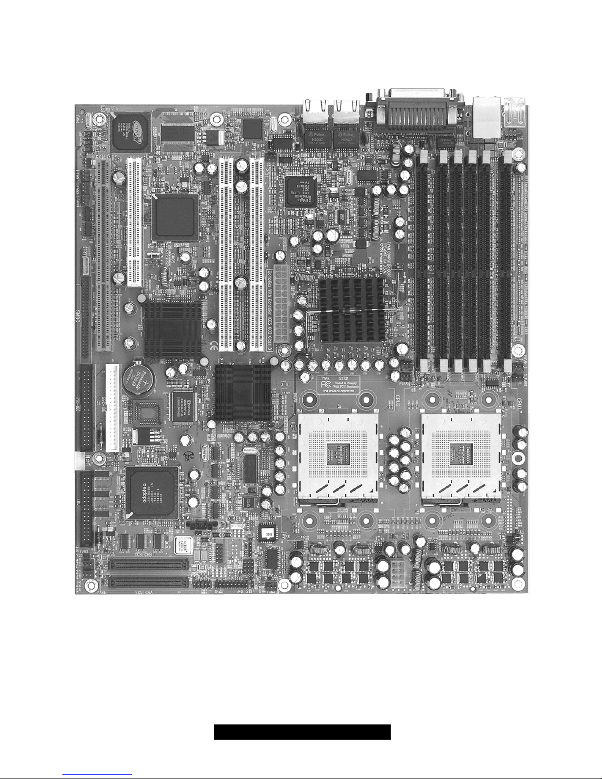
The following is an image of the S2721 Thunder i7500 Pro.
The above photograph is purely representative. Due to engineering updates and new board
revisions, certain components may change and or be repositioned. The picture above may
or may not look exactly like the board you received.
The following page includes details on the vital components of this motherboard.
8
http://www.TYAN.com
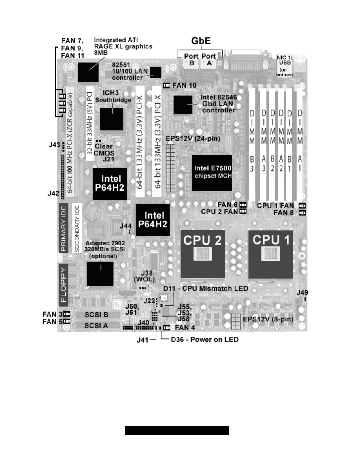
2.2 – Board Jumpers, LEDs, and Fans
This jumper diagram is representative of the latest board revision available at the time of
publishing. The board you receive may or may not look exactly like the above diagram.
IMPORTANT NOTE:
Fan locations as labeled on some revisions of the motherboard may be incorrect. It is highly
recommended if you intend to monitor fans, that you use the information in this manual for
accuracy. If you found the addendum in your package you absolutely will need to follow the
manual for accurate location and function of fan headers.
9
http://www.TYAN.com
2.3 – Jumper Definitions
* WOL is only supported by NIC1 (82551QM, 10/100 Mbps). See page 8.
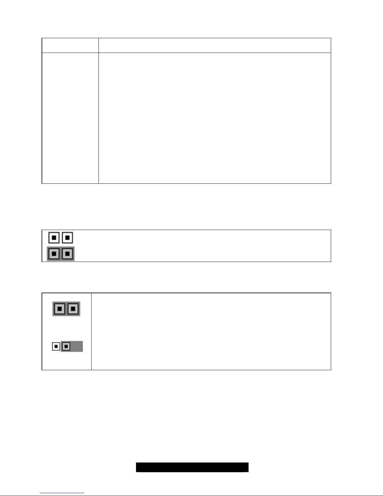
Jumper Example
Jumper OFF – open (without jumper cover)
Jumper ON – closed (with jumper cover)
CMOS Reset (J21)
1
Clear CMOS
1
Normal
You can reset the CMOS settings in case an incorrect setting causes system
instability or you have forgotten your system/setup password or have just
flashed your BIOS by using these jumpers.
- Power off system, disconnect power supply from motherboard
- Set jumper J21 to Clear CMOS
- Wait about 5 seconds
- Set jumper J21 to Normal
Jumper Function
J21
J22
J38 *
J40
J41
J42
J43
J44
J49
J50
J51
J53 & J58
(Port A/Port B)
J55
Clear CMOS
External speaker header
Wake On LAN
Front Panel connector
Hard drive external activity LED
SMDC connector (Server Management daughter card)
I2C bus connector
PCI-X Force 100Mhz (see description on the next page)
Hyper -Threading (see description on the next page)
USB internal port #3
USB internal port #4
Intel GbE 82546 4-pin external LAN activity/link
LED headers. Note: Left most pin is pin1.
Intel 82551 4-pin external LAN activity/link LED header
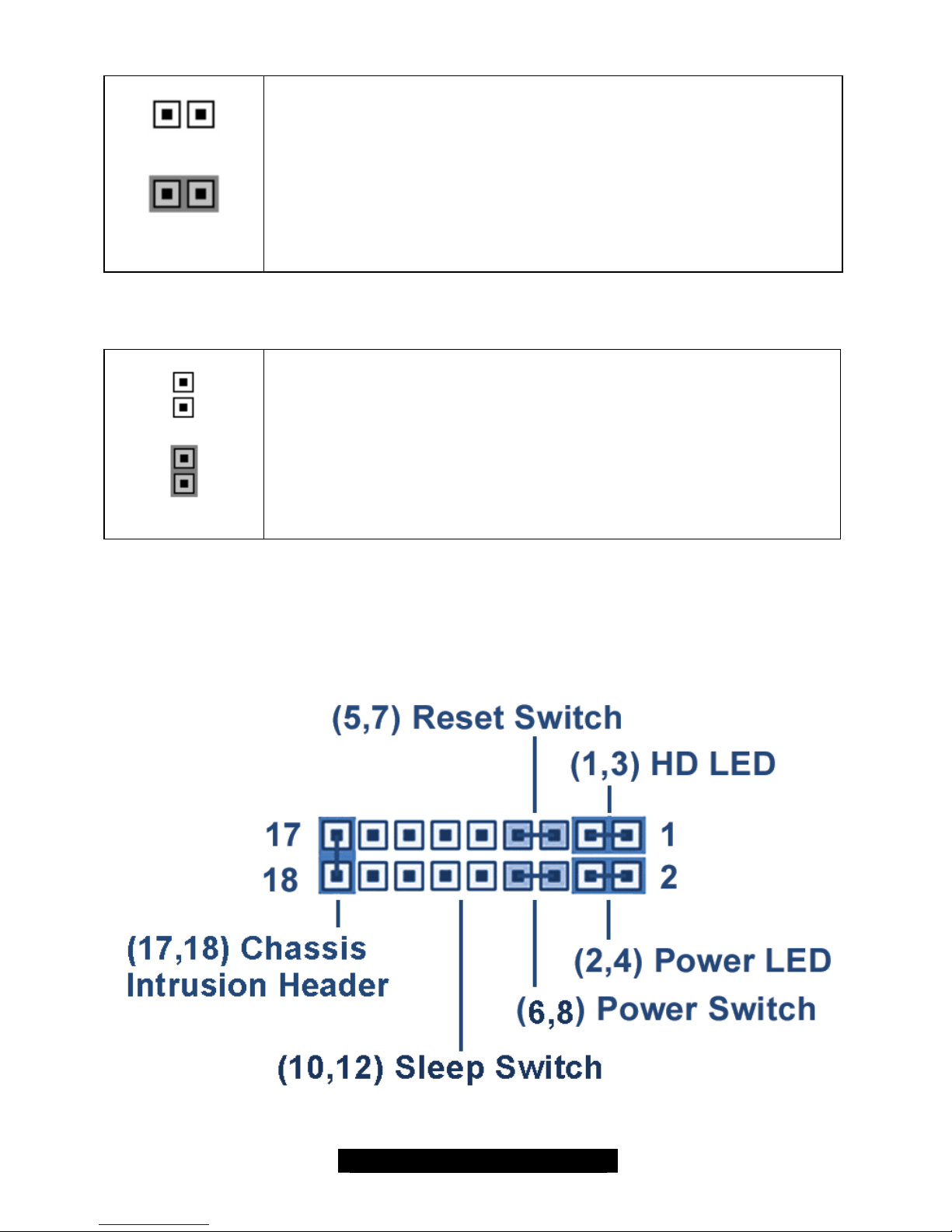
10
http://www.TYAN.com
PCI-X Force 100MHz (J44)
.
Normal
Force 100MHz
Jumper open = Card dependent, will run at PCI-X capability of card
inserted up to PCI-X 133.
Jumper closed = Forces 100Mhz on PCI-X slot 1 (see next page for
slot location).
NOTE: This ONLY effects the PCI1 slot as labeled on the board.
Hyper-Threading (J49)
Normal
Hyper - Threading
Disabled
Jumper open = BIOS controls Hyper-Threading.
Jumper closed = Disables Hyper-Threading, no matter what the BIOS
setting is.
Front Panel Connector (J40)
Your chassis will usually come with connectors to install onto the motherboard, such as HD and
Power LEDs. The Front Panel Connector (J40) has been implemented for such purposes.

11
http://www.TYAN.com
2.4 – LED Information
LEDs Description
D11
D36
CPU Voltage Mismatch (LED)
Red LED activates if single CPU is placed in CPU 2 socket. May also
activate if CPUs are mismatched – ie. Using two different Xeons. If
installing only one CPU, it must be placed in CPU 1. (Light will remain off
if CPUs are placed correctly.)
Power on LED
2.5 – Fan Header Information
Fan # Fan Description Functions Amp Rated
1 CPU 2 fan RPM Read and controlled 1.2A
2 CPU 1 fan RPM Read and controlled 1.2A
3 Chassis fan 3 RPM Read and controlled 1.2A
4 Chassis fan 4 RPM Read 1.2A
5 Chassis fan 5 RPM Read 1.2A
6 Chassis fan 6 RPM Read 1.2A
7 Chassis fan 7 None 2A
8 Chassis fan 8 None 2A
9 Chassis fan 9 None 2A
10 Chassis fan 10 None 2A
11 Chassis fan 11 None 2A
12
http://www.TYAN.com
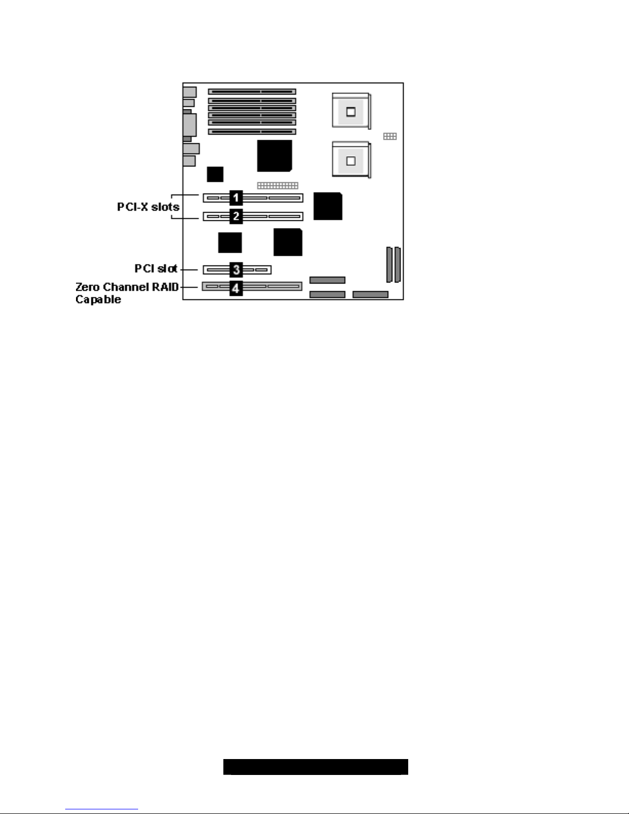
2.6 – PCI Setup
Slot (1, 2): 64-bit 133MHz (3.3V) PCI-X
- 3.3 volt cards accepted
Slot (3): 32-bit 33MHz (5V) PCI
- 5 volt and 3.3 volt cards accepted
Slot (4): 64-bit 100MHz PCI-X
- 3.3 volt cards accepted
- Supports Zero Channel RAID
The PCI slots on the Thunder i7500 Pro operate on independent PCI buses, which gives
you maximum bandwidth.
13
http://www.TYAN.com
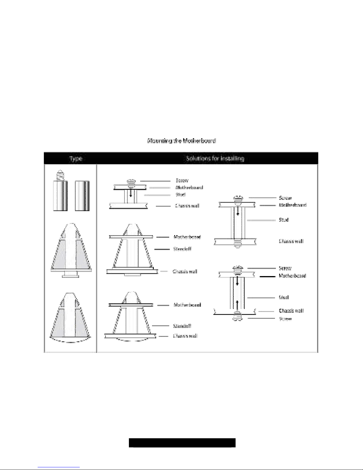
2.7 – Mounting the Motherboard
Before installing your motherboard, make sure your chassis has the necessary motherboard
support studs installed. These studs are usually metal and are gold in color. Usually, the chassis
manufacturer will pre-install the support studs. If you’re unsure of stud placement, simply lay the
motherboard inside the chassis and align the screw holes of the motherboard to the studs inside
the case. If there are any studs missing, you will know right away since the motherboard will not
be able to be securely installed.
Some chassis’ include plastic studs instead of metal. Although the plastic studs are usable, Tyan
recommends using metal studs with screws that will fasten the motherboard more securely
in place.
Below is a chart detailing what the most common motherboard studs look like and how they
should be installed.
TIP: Use metal studs if possible, as they hold the motherboard into place more securely than
plastic standoffs.
14
http://www.TYAN.com
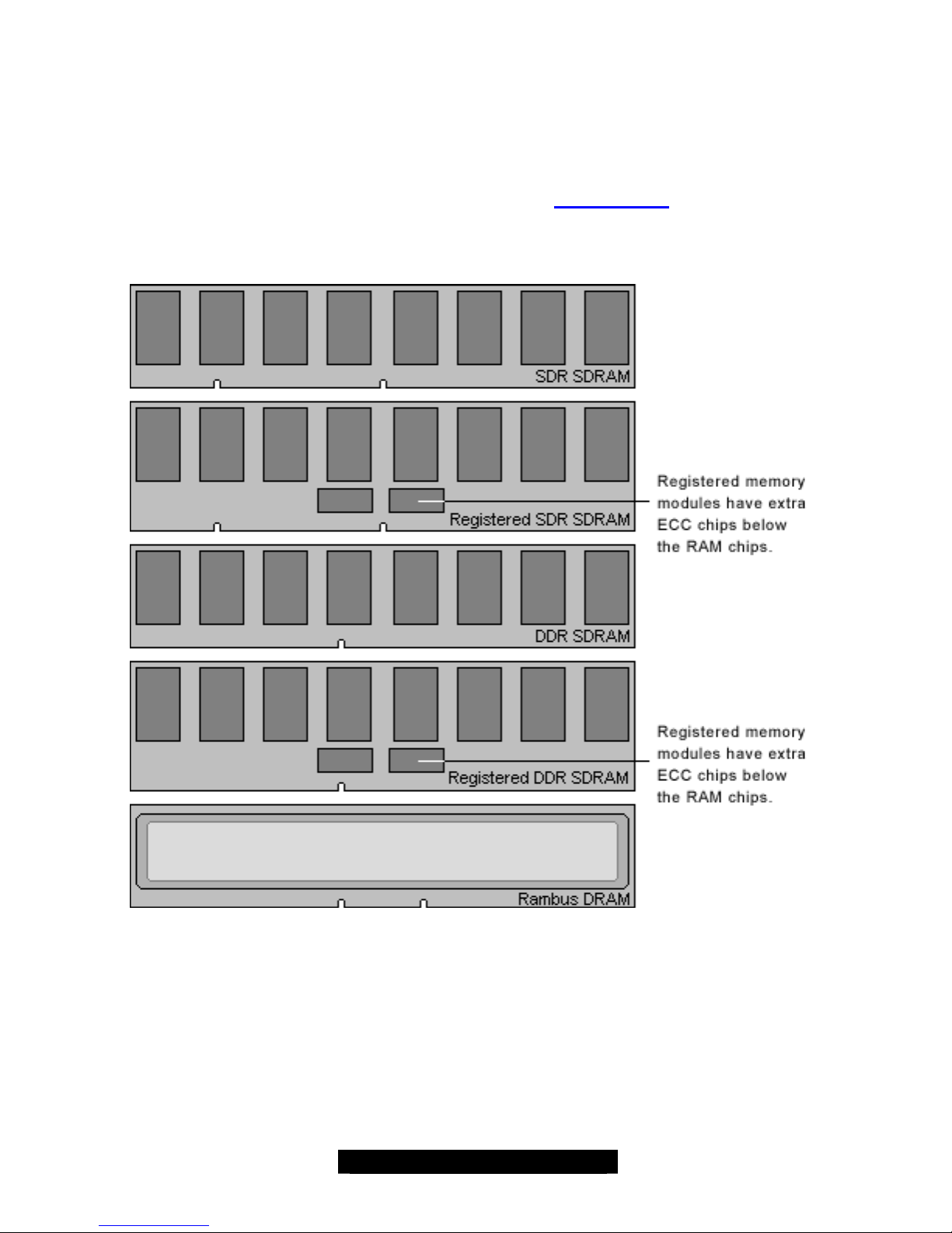
2.8 – Installing the Memory
Before attempting to install any memory, make sure that the memory you have is compatible with
the motherboard as well as the processor. For example, while PC1600 DDR modules are
compatible with all DDR based motherboards, they will not work if you are required to run the
motherboard and processor buses at 133MHz. For this, PC2100 DDR modules are required.
Critically important is whether you’re using the recommended memory for the current board you
have. For this information, please check Tyan’s web site at: www.tyan.com
The following diagram shows the types of RAM modules you may encounter depending on your
board:
 Loading...