

TYAN S2692, Tiger i5000XL User Manual

http://www.tyan.com
1
Tiger i5000XL
///
S2692
Version 1.0
Copyright
Copyright © TYAN Computer Corporation, 2006. All rights reserved. No part of
this manual may be reproduced or translated without prior written consent from
TYAN Computer Corp.
Trademark
All registered and unregistered trademarks and company names contained in
this manual are property of their respective owners including, but not limited to
the following.
TYAN, Taro and Tiger i5000XL are trademarks of TYAN Computer Corporation.
AMD, Opteron, and combinations thereof are trademarks of AMD Corporation.
Intel, Xeon, and combinations thereof are trademarks of Intel Corporation.
Nvidia and nForce are trademarks of Nvidia Corporation
Microsoft, Windows are trademarks of Microsoft Corporation.
SuSE,is a trademark of SuSE AG.
Linux is a trademark of Linus Torvalds
IBM, PC, AT, and PS/2 are trademarks of IBM Corporation.
Winbond is a trademark of Winbond Electronics Corporation.
Notice
Information contained in this document is furnished by TYAN Computer
Corporation and has been reviewed for accuracy and reliability prior to printing.
TYAN assumes no liability whatsoever, and disclaims any express or implied
warranty, relating to sale and/or use of TYAN products including liability or
warranties relating to fitness for a particular purpose or merchantability. TYAN
retains the right to make changes to product descriptions and/or specifications
at any time, without notice. In no event will TYAN be held liable for any direct or
indirect, incidental or consequential damage, loss of use, loss of data or other
malady resulting from errors or inaccuracies of information contained in this
document.

http://www.tyan.com
2
Table of Contents
Chapter 1: Introduction
1.1 Congratulations Page 5
1.2 Hardware Specifications Page 5
Chapter 2: Board Installation
2.1 Board Image Page 8
2.2 Block Diagram Page 9
2.3 Board Parts, Jumpers and Connectors Page 10
2.4 Mounting the Motherboard Page 22
2.5 Installing the Memory Page 23
2.6 Installing the Processor and Cooling Fan Page 25
2.7 Attaching Drive Cables Page 27
2.8 Installing Add-In Cards Page 29
2.9 Installing Optional SO-DIMM Modules Page 32
2.10 Connecting External Devices Page 33
2.14 Installing the Power Supply Page 34
2.15 Finishing Up Page 35
Chapter 3: BIOS
3.1 About the BIOS` Page 37
3.2 Main BIOS Setup Page 39
3.3 Main Page 40
3.4 Advanced Page 46
3.5 Security Page 58
3.6 Power Page 59
3.7 Boot Page 60
3.8 Exit Page 61
Chapter 4: SATA/RAID Setup
4.1 BIOS Configuration Page 63
4.2 Installing Serial ATA (SATA) hard disks Page 63
4.3 Adaptec RAID Configuration Utility Page 64
4.4 Manage Array Page 64
4.5 Create Array Page 66
4.6 Add/Delete Hotspare Page 68
4.7 Initialize Drives Page 68
4.8 Disk Utilities Page 70
Chapter 5: Diagnostics
5.1 Beep Codes Page 73
5.2 Flash Utility Page 73
5.3 BIOS Post Code Page 74
Appendix I: SMDC Information
Page 79
Appendix II: How to Make a Driver Diskette
Page 81
Glossary
Page 83
Technical Support
Page 89
http://www.tyan.com
3
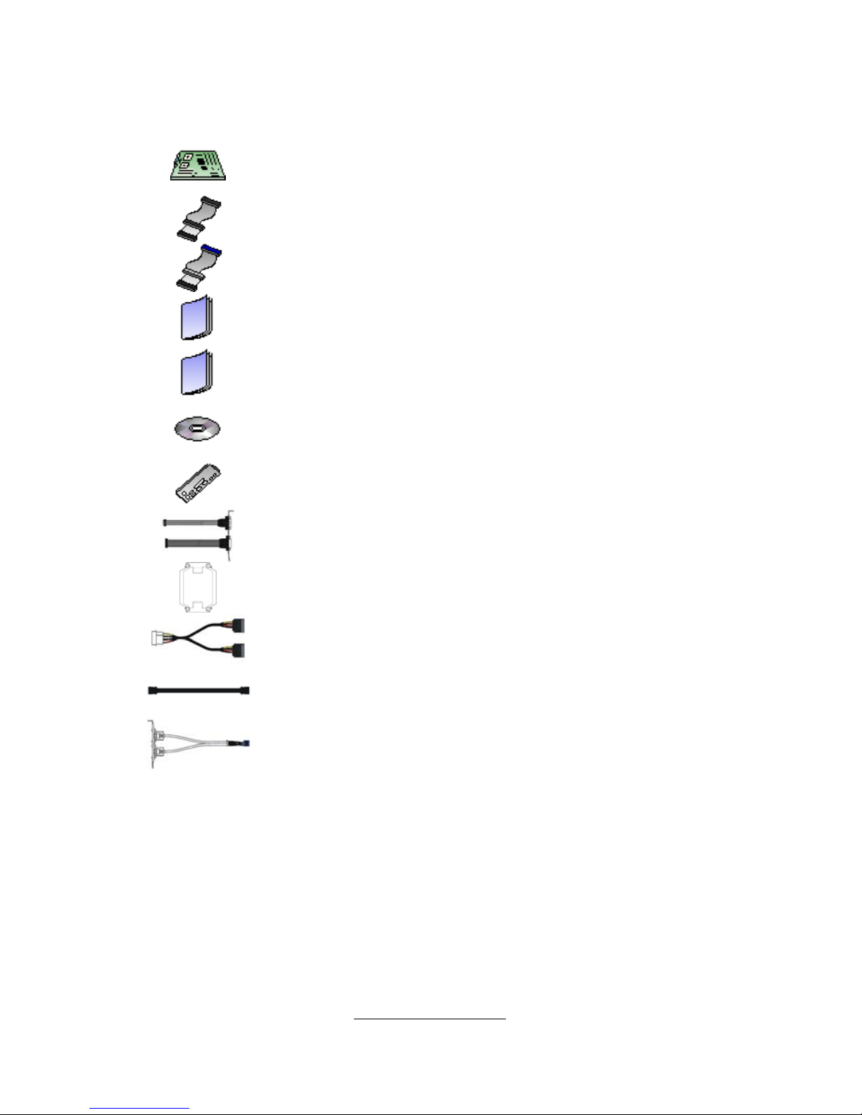
Check the box contents!
The retail motherboard package should contain the following:
1 x Tiger i5000XL S2692 motherboard
1 x 34-Pin floppy drive cable
2 x Ultra-DMA-133/100/66/33 IDE cable
1 x Tiger i5000XL S2692 User’s Manual
1 x Tiger i5000XL S2692 Quick Reference Guide
1 x TYAN driver CD
1 x I/O shield
1 x Cable set (9 pin serial and 24 pin parallel)
2 x CEK Spring
1 x Serial ATA power cable
2 x Serial ATA cable
1 x USB2.0 cable
If any of these items are missing, please contact your vendor/dealer for
replacement before continuing with the installation process.

http://www.tyan.com
4
NOTE

http://www.tyan.com
5
Chapter 1: Introduction
1.1 - Congratulations
Congratulations on your purchase of the powerful Dual Intel processor solution,
the Tiger i5000XL S2692. Based on Intel® 5000X Greencreek MCH and Intel®
6321ESB I/O Controller chipsets, the S2692 offers exceptional performance.
Compatible with EPS12V power supplies, the CEB form factor S2692 features
an onboard RealTek ALC888 audio controll er, one 10/100/1000 Ethernet port
and SATA/RAID, which provides a versatile solution for your workstation needs.
Remember to visit TYAN’s Website at http://www.tyan.com. There you can find
information on all of TYAN’s products with FAQ’s, online manuals and BIOS
upgrades.
1.2 - Hardware Specifications
Processors
Dual LGA771 sockets
Supports up to two Dual-Core Intel®
Xeon® Processors 5000/5100 Series
processors
1333/1066 MHz FSB
VRD11.0
Chipset
Intel® 5000X Greencreek MCH +
Intel® 6321ESB I/O Controller
Winbond W82627EHF Super I/O
chip
Memory
Four 240-pin DDR2 FBDIMM sockets
Four memory channels
Supports ECC DIMMs
Maximum of 16/8GB DDR2-533/667
Integrated LAN Controllers
Intel® 82564 Gilgal Single-Port
GbE – ASF 2.0
One RJ-45 port with LEDs
Integrated I/O
One 9-pin 16550 UART serial port
Eight USB 2.0 ports (four at rear,
four via headers)
PS/2 mouse and keyboard
connectors
Six Standard/integrated SATA2
connectors
One RJ-45 10/100/1000 LAN
ports
One IDE and one Floppy
connectors
Integrated Serial ATAII (SATA-II)
RAID
Six (6) SATA-II ports
3.0 Gb/s per port
RAID 0, 1, 10 supported
BIOS
Phoenix TrustedCore BIOS on
8Mbit Flash ROM
Supports APM 1.2, ACPI 2.0
Serial Console Redirect
PXE via Ethernet, USB device

http://www.tyan.com
6
Expansion Slots
One (1) PCI Express x16 slot with
x16 signal
One (1) PCI Express x8 slot with x4
signal
One (1) PCI Express x16 slot with x8
signal
Two (2) PCI-X 133/100MHz slots
One (1) PCI 32-bit 33MHz slot
Total six (6) expansion slots
System Management
ADT7470 Hardware Monitor
CPU thermal & voltage monitor
support
Five (5) fan headers (4-pin
configuration)
Integrated Audio Controller
HDA link
RealTek ALC888 controller (High
Definition Audio)
Line-in, Line-out, Mic-in rear ports
SPDIF In/Out in rear
Front panel audio header
CD-in, Aux headers (4-pin
configuration)
Regulatory
FCC Class B (DoC)
European Community CE (DoC)
BSMI
boot
PnP, DMI 2.0 WfM 2.0 Power
Management
User-configurable H/W monitoring
Auto-configuration of hard disk
types
Multiple boot options
48-bit LBA support
Form Factor
CEB (12” x 10.5”)
EPS 12V/SSI (24+8 pin) power
connectors
Stacked PS/2 keyboard and
mouse connectors
One Serial port
Stacked USB 2.0 (2)
Stacked USB 2.0 (2) and RJ-45
(1) connectors
Stacked Line-in, Line-out, Mic-in
audio connectors
SPDIF port
Power
On board dual 4-phase VRM
EPS 12V (24-pin + 8-pin) power
connectors

http://www.tyan.com
7
Chapter 2: Board Installation
Precautions: The Tiger i5000XL supports SSI, EPS12V type power supplies
(24pin + 8pin) and will not operate with any other types. For proper power
supply installation procedures see page 37.
DO NOT USE ATX 2.x or ATXGES power supplies as they will damage the
board and void your warranty.
How to install our products right… the first time
The first thing you should do is reading this user’s ma nual. It contains important
information that will make configuration and setup much easier. Here are some
precautions you should take when installing your motherboard:
(1) Ground yourself properly before removing your motherboard from the
antistatic bag. Unplug the power from your computer power supply and
then touch a safely grounded object to release static charge (i.e. power
supply case). For the safest conditions, TYAN recommends wearing a
static safety wrist strap.
(2) Hold the motherboard by its edges and do not touch the b ottom of the
board, or flex the board in any way.
(3) Avoid touching the motherboard components, IC chips, connectors,
memory modules, and leads.
(4) Place the motherboard on a grounded antistatic surface or on the
antistatic bag that the board was shipped in.
(5) Inspect the board for dama ge .
The following pages include details on how to install your motherboard into your
chassis, as well as installing the processor, memory, disk drives and cables.
NOTE
DO NOT APPLY POWER TO THE BOARD IF IT HAS BEEN
DAMAGED.
http://www.tyan.com
8
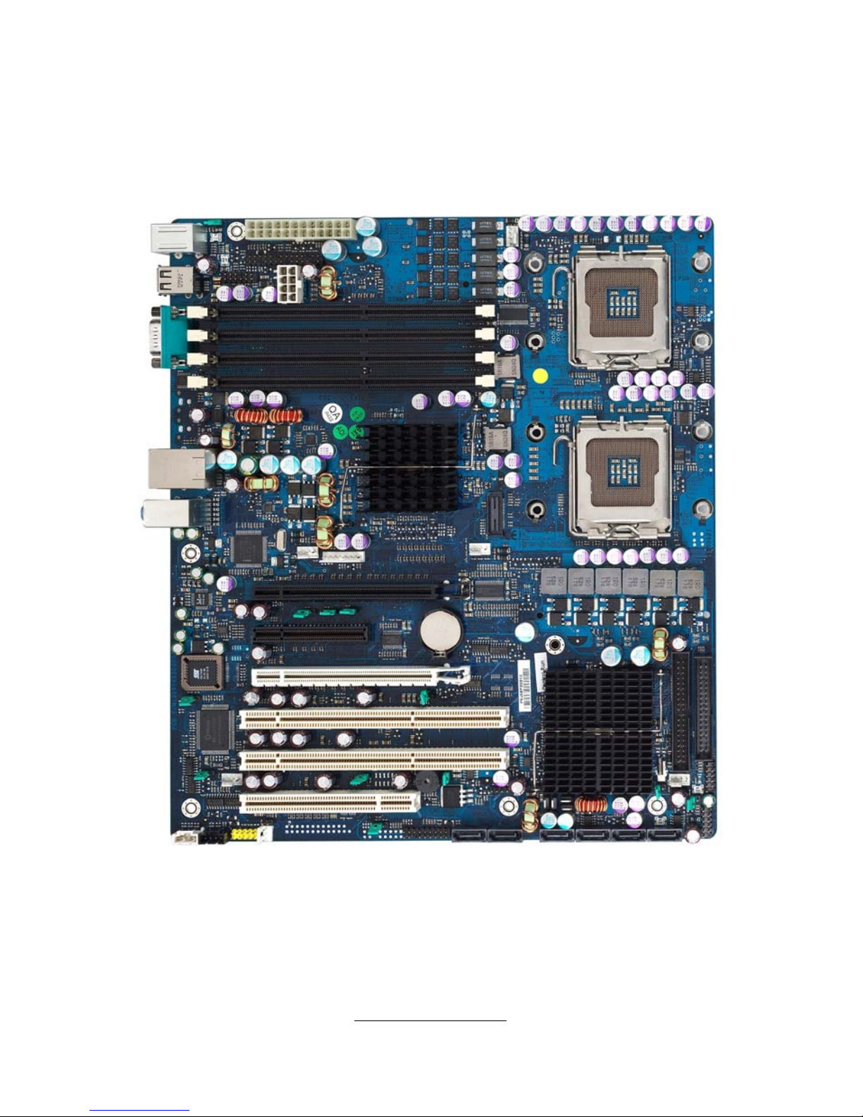
2.1- Board Image
This picture is representative of the latest board re vision available at
the time of publishing. The board you receive may or may not look
exactly like the above picture.
The following page includes details on the vital components of this
motherboard.
http://www.tyan.com
9
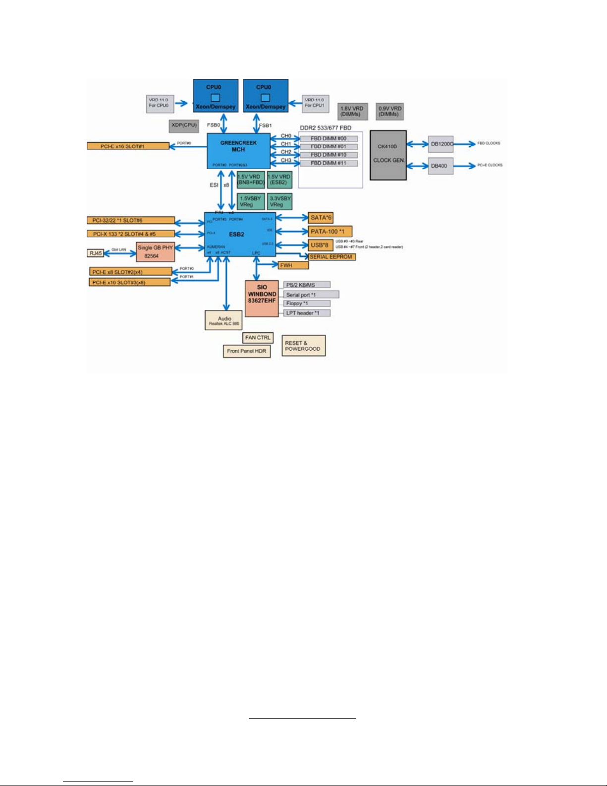
2.2 - Block Diagram
Tiger i5000XL (S2692) Block Diagram
http://www.tyan.com
10
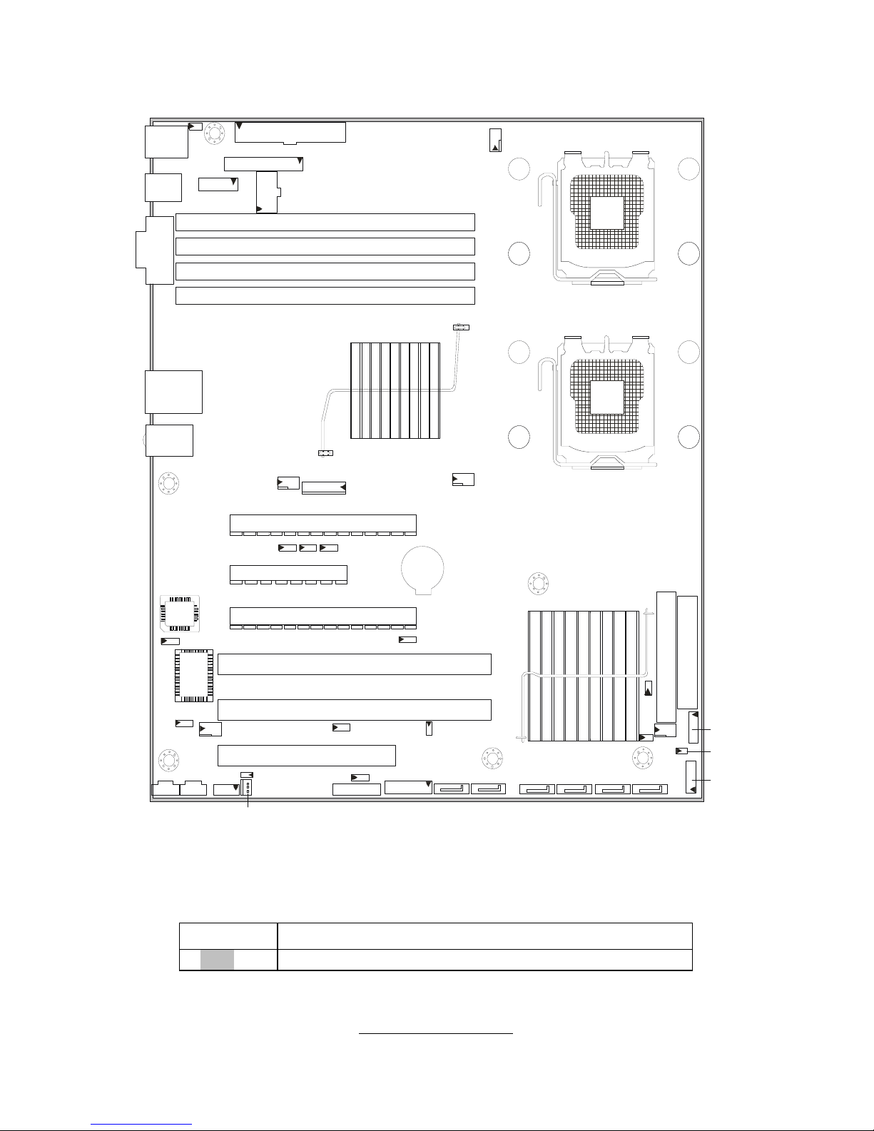
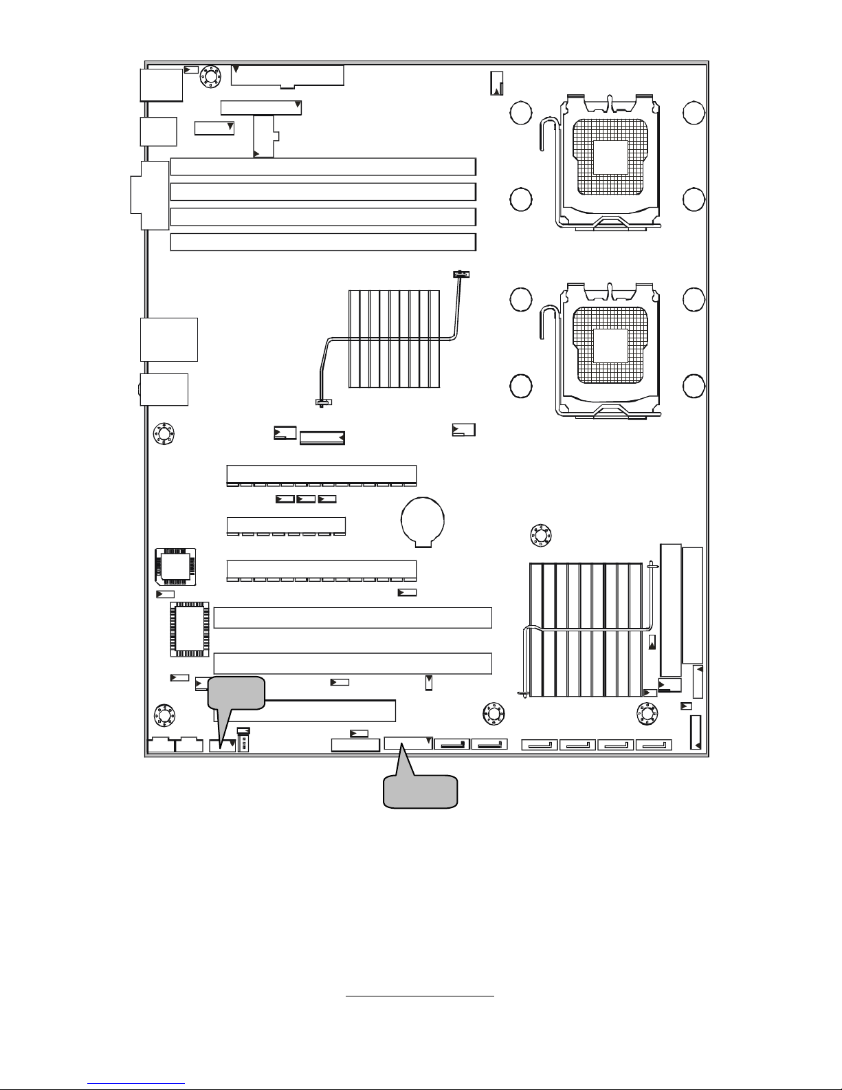
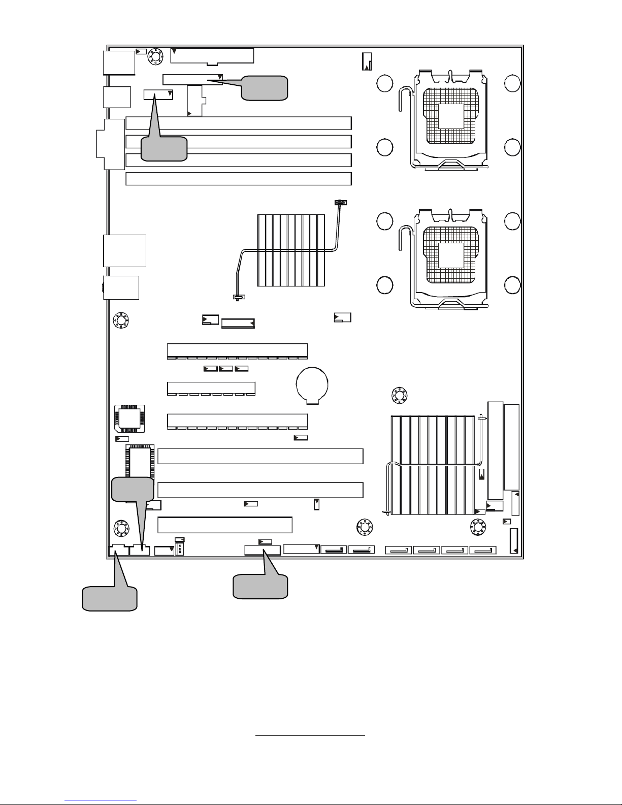
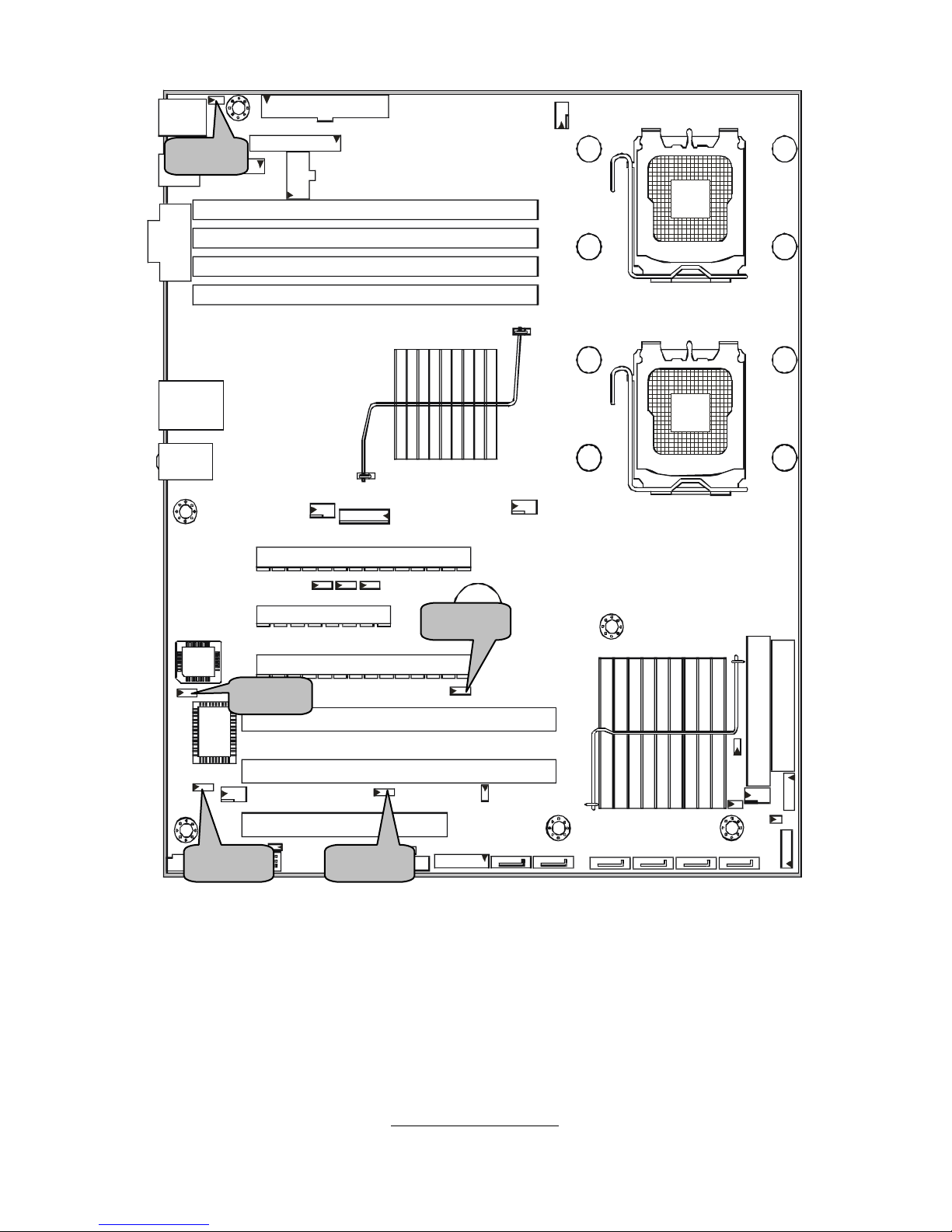
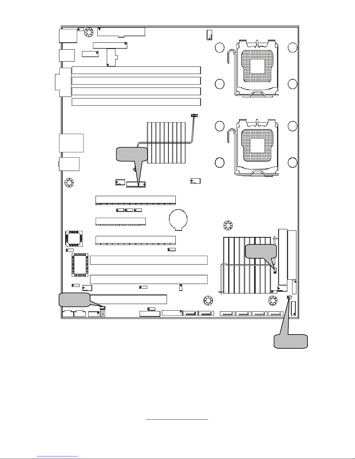
2.3 - Board Parts, Jumpers and Connectors
JP16
P2
PS/2
KB/MS
USB x 2
COM
RJ45
USB x 2
L-in
L-out
Mic
JP25
CN1
J1 2
J1 3
CN3
DIMM0
DIMM1
DIMM2
DIMM3
CN21
CPU0
CPU1
CN20
CN22
J11
PCIE x16 Slot (x16)
CN24
P3
JP20
JP23
J7
JP15
JP26
JP1 8
CN19
JP5
SATA0 SATA1 SATA2 SATA 3
SATA4 SATA5
CN15
CN28
FDD
IDE
CN2 3
JP19
JP27
PCIE x8 S lot (x4)
PCIE x16 Slot (x8)
PCIX 133 Slot
PCIX 133 Slot
PCI 33 Slot
JP7
JP8
JP6
JP24
JP14
P1
This diagram is representative of the latest board revision available at the time of
publishing. The board you receive may not look exactly like the above diagram.
Jumper Legend
OPEN - Jumper OFF, without jumper cover
CLOSED – Jumper ON, with jumper cover
http://www.tyan.com
11
Jumper/Connector Function
CN20/21/22/23/24 4-pin FAN Connector
J12/J13 LEC/LCD Interface Connector
P2 CD_IN Connector
P3 AUX_IN Connector
J7 Audio Front Panel Connector
J11 PC2004 Power Supply Connector
J16 3-pin Chassis Intrusion Header
CN15/CN28 USB2.0 Connector
JP6/JP7/JP8 CPU Bus Clock Select Jumper
JP5 Clear CMOS Jumper
JP19 BIOS Recovery Jumper
JP20 FWH Write Protect Jumper
JP18 Internal buzzer Enable/Disable Jumper
JP23 LAN Enable/Disable Jumper
JP24 PCIX Frequency Setting Jumper
JP25 PS/2 Wake Up Jumper
JP26 Power for Hardware Monitor
JP27 Reset Signal for Hardware Monitor
JP14/JP15 External Thermal Diode Header

http://www.tyan.com
12
CN21
CN15
CN20CN22
J16
CN28
CN24
CN23
http://www.tyan.com
13
CN15: USB2.0 Connector
10
2
9
1
This is used to connect 2 USB 2.0 ports on USB2.0
connector.
Signal Pin Pin Signal
USBPWR 1 2 USBPWR
USB_2D- 3 4 USB_3D-
USB_2D+ 5 6 USB_3D+
GND 7 8 GND
KEY 9 10 NC
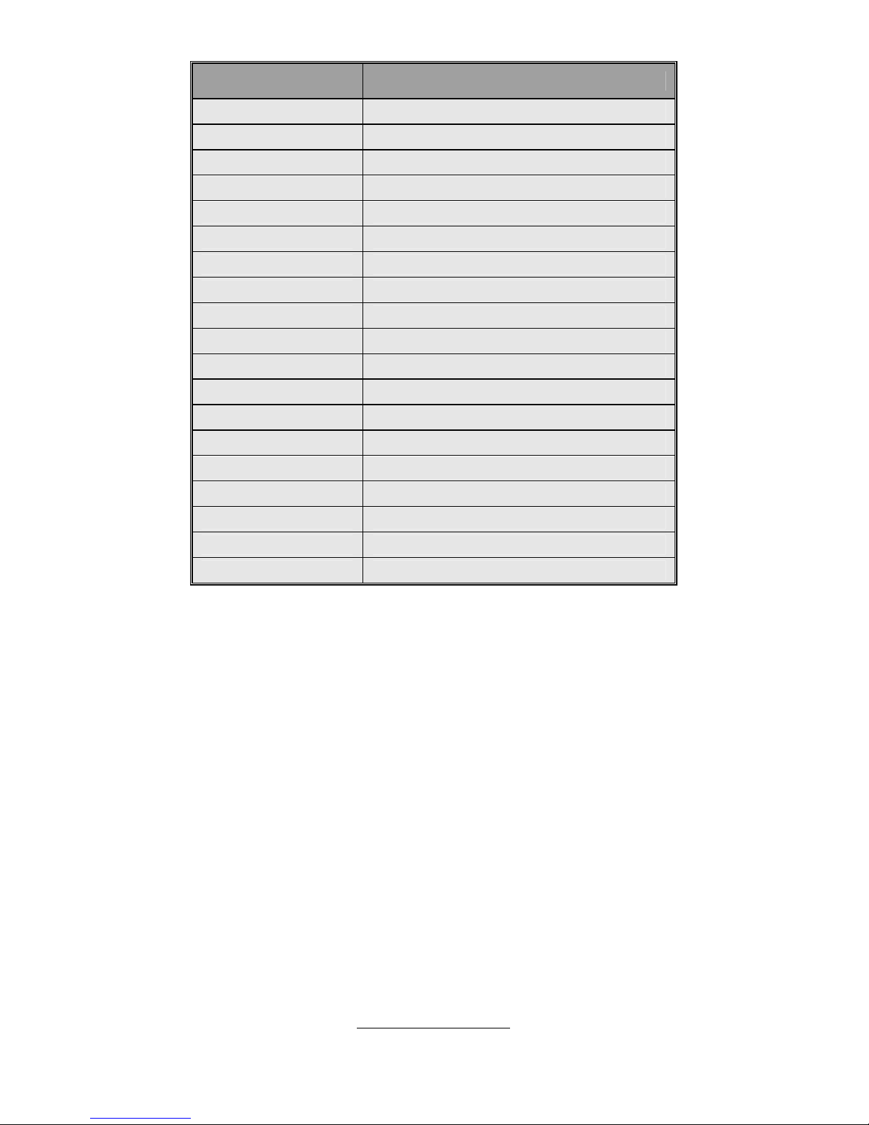
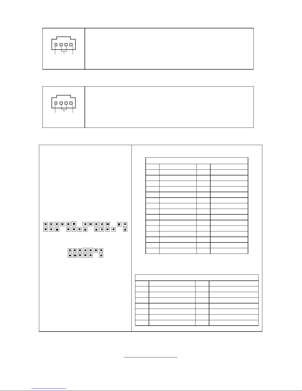
CN20/CN21/CN22/CN22/CN23: 4-pin FAN Connector
Use these headers to connect the cooling fans to the
motherboard to keep the system stable and reliable.
Pin 1 Pin 2 Pin 3 Pin 4
GND +12V Tachometer Fan PWM (speed)
Control
J16: 3-pin Chassis Intrusion Header
1
Pin Signal
1 Detect signal
Low means intruder device pluged.
2 Signal intruder
3 GND
http://www.tyan.com
14
J7
CN19
http://www.tyan.com
15
CN19: Front Panel Header
SMBUS Clock
SMBUS Data
5VSB
Non-mask
Interrupt (NMI)
RESET
Switch
HDD LED-
HDD LED+
17
15
13
11
9
7 5
3
1
18
16
14
12
10 8 6
4 2
NC
GND
Key
Warning LED-
Warning LED+
POWER
Switch
PWR LED-
PWR LED+
The motherboard
provides one front
panel header for
electrical
connection to the
front panel
switches and
LED’s.
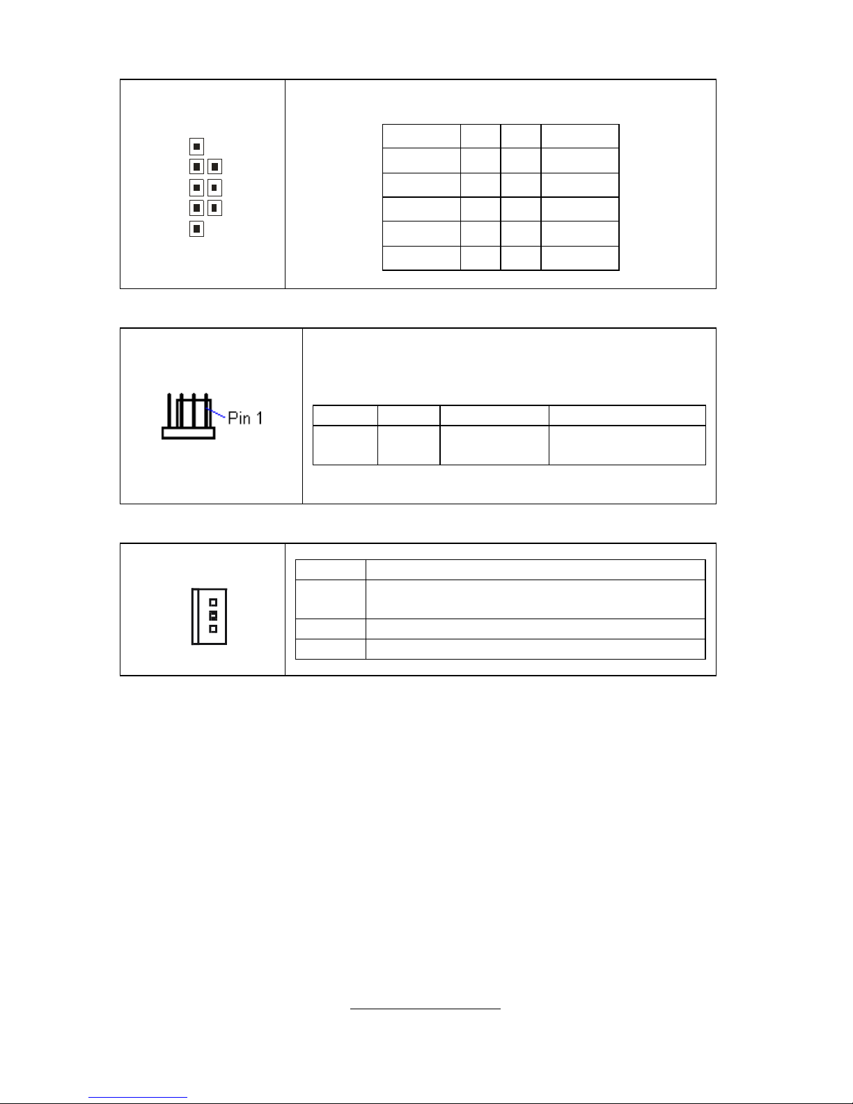
J7: Front Panel Audio Connector
10 2
9 1
The front panel audio connector allo ws you to connect
to the front panel audio. It contains line-out and MIC
signal for front panel.
PIN Signal
1 AUD_MIC_L
2 GND
3 AUD_MIC_R
4 AFP_PRESENT
5 AUD_FP_R
6 MIC_JD
7 F_AUD_DET
8 KEY
9 AUD_FP_L
10 LINE_JD
J11: Power Supply Header (for FSC)
1
It can detect and contoll FSC power supply's FAN
speed.
http://www.tyan.com
16
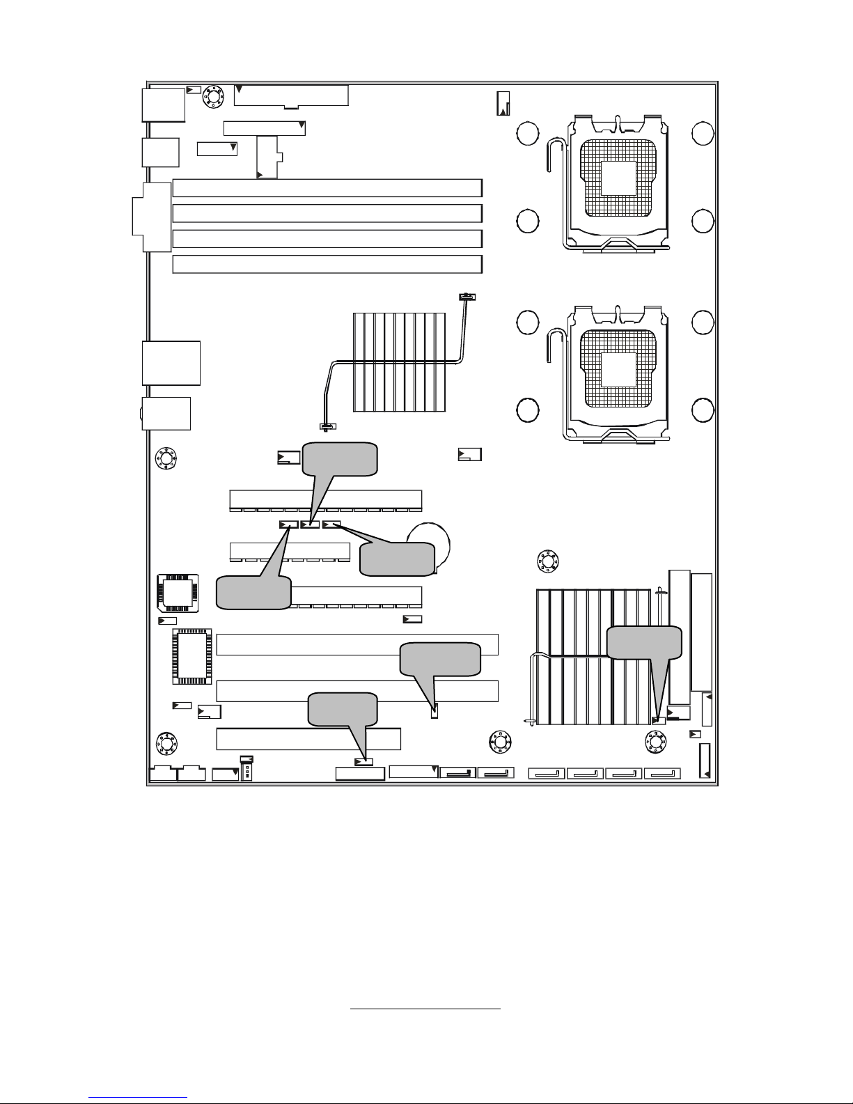
P1
P3
J12
P2
J13
http://www.tyan.com
17
P2: CD_IN Connector
RGND
L
This is for CD-ROM audio connector.
P3: AUX_IN Connector
RGND
L
AUX_IN is used for input and mixing of MPEG, TV tuner, or
other audio sources.
J12/J13: LED Interface Connector (reserved)
J1
2
30
29
1
2
J13
1
2
13
1
4
J12
Pin Signal Pin Signal
1 GND 2 SPKR_OUT_L
3 SLP_LED+ 4 <KEY>
5 <KEY> 6 GND
7 PWR_LED+_0 8 SPKR_OUT_H
9 PWR_LED+_1 10 NC1
11 GND 12 NC2
13 3.3V 14 <KEY>
15 MSG_LED- 16 NC3
17 <KEY> 18 SCSI_LED-_0
19 3.3V 20 SCSI_LED-_1
21 HD_LED- 22 NC4
23 GND 24 <KEY>
25 PWRBTN_N 26 GND
27 SLPBTN_N 28 GND
29 RESET_N 30 GND
J13 is reserved for FSC only.
J13
Pin Signal Pin
1 LCD_SMBCLK 2 GND
3 LCD_SMBDAT 4 GND
5 KEY 6 LCD_LAN_LNK1000
7 LCD_LAN_ACT_L 8 LCD_LAN_LNK_L
9 LCD_IDE_LED_L 10 LCD_ALERT_L
11 LCD_MSG 12 LCD_SLEEP_L
13 LCD_PWR_ACT_L 14 LCD_VDD
http://www.tyan.com
18
JP8
JP19
JP5
JP7
JP6
JP18
http://www.tyan.com
19
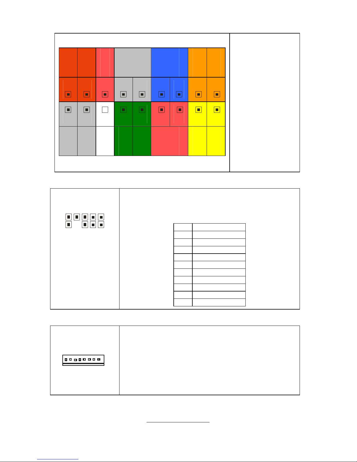
P1: High Definition Audio Header
1
2
1
5
1
6
P1 is a standard HDA header,you can plug
another HDA audio card on it
.
Pin Signal Pin Signal
1 ACZ_BIT_CLK_HDA 2 GND1
3 ACZ_RST_N_HDA 4 DVDD
5 ACZ_SYNC_HDA 6 GND2
7 ACZ_SDOUT_HDA 8 DVDD_CORE
9 ACZ_ADIN_0_HDA 10 +12V
11 FNT_PRT_N_HDA 12 KEY
13 ACZ_SDIN_1_HDA 14 3.3VSBY
15 ACZ_SDIN_2_HDA 16 GND3
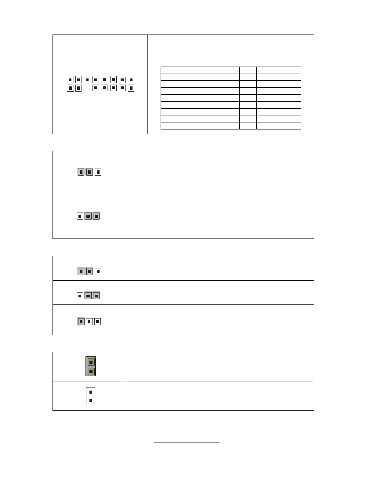
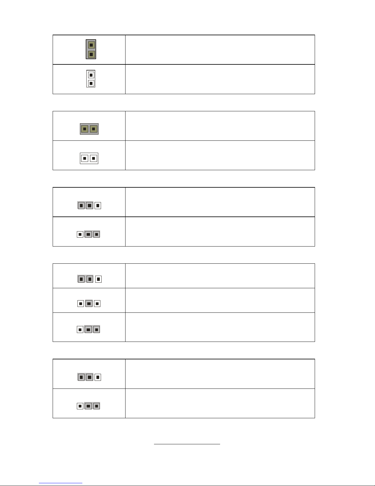
JP5: Clear CMOS Jumper
3
1
Default
1
3
Clear
You can reset CMOS settings by using this jumper if
you have lost your system/setup password or need to
clear the system BIOS settings.
Power off the system and set JP5 to (2-3) position, and
then power on the system. The CMOS will be cleared
when the POST screen is visible. Finally shut down the
power and move JP5 to it’s default (1-2) position and
power on the system again.
JP6/JP7/JP8: CPU Bus Clock Select Jumper
3
1
1-2 close: CPU select (Default)
1
3
2-3 close: 0
1
3
2-3 open: 1
JP18: Internal Buzzer Enable/Disable Jumper
1
Close: enable internal buzzer (Default)
1
Open: disable internal buzzer
http://www.tyan.com
20
JP24
JP23
JP25
JP20 JP26
http://www.tyan.com
21
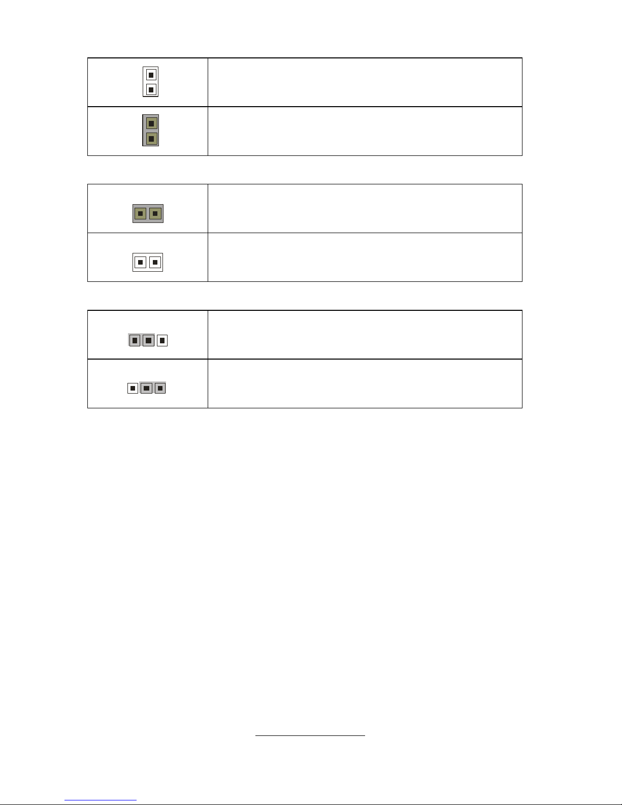
JP19: BIOS Recovery Jumper
1
Close: enable internal buzzer (Default)
1
Open: disable internal buzzer
JP20: FWH Write Protect Jumper
1
Close: write protect (Default)
1
Open: normal
JP23: LAN Enable/Disable Jumper
3
1
1-2 Close: enable LAN (Default)
1
3
2-3 Close: disable LAN
JP24: PCI-X Frequency Setting Jumper
3
1
1-2 close: (Default) – 100MHz
1
3
2 close: 133MHz
1
3
2-3 close: 66MHz
JP25: PS/2 Wake Up Jumper
3
1
1-2 Close: not supporting PS/2 wake up function
(Default)
1
3
2-3 Close: supporting PS/2 wake up function
http://www.tyan.com
22
JP27
JP14
JP15
J11
http://www.tyan.com
23
JP26: Power for Hardware Monitor Jumper
1
Open: debug only
1
Close: normal operation
JP27: Reset Signal for Hardware Monitor Jumper
1
Close: write protect (Default)
1
Open: normal
JP14/JP15: External Thermal Diode Header (for FSC)
3
1
1-2 Close: enable LAN (Default)
1
3
2-3 Close: disable LAN
 Loading...